EP2287827A1 - Appareil et système de face arrière de projection - Google Patents
Appareil et système de face arrière de projection Download PDFInfo
- Publication number
- EP2287827A1 EP2287827A1 EP10157053A EP10157053A EP2287827A1 EP 2287827 A1 EP2287827 A1 EP 2287827A1 EP 10157053 A EP10157053 A EP 10157053A EP 10157053 A EP10157053 A EP 10157053A EP 2287827 A1 EP2287827 A1 EP 2287827A1
- Authority
- EP
- European Patent Office
- Prior art keywords
- frame
- hinge assemblies
- screen
- members
- projection screen
- Prior art date
- Legal status (The legal status is an assumption and is not a legal conclusion. Google has not performed a legal analysis and makes no representation as to the accuracy of the status listed.)
- Withdrawn
Links
- 230000000712 assembly Effects 0.000 claims abstract description 67
- 238000000429 assembly Methods 0.000 claims abstract description 67
- 239000004744 fabric Substances 0.000 claims abstract description 54
- 230000013011 mating Effects 0.000 claims description 23
- 239000000463 material Substances 0.000 claims description 12
- 238000003780 insertion Methods 0.000 claims description 4
- 230000037431 insertion Effects 0.000 claims description 4
- 230000006835 compression Effects 0.000 claims description 2
- 238000007906 compression Methods 0.000 claims description 2
- 238000000034 method Methods 0.000 description 5
- 230000002093 peripheral effect Effects 0.000 description 4
- 230000001737 promoting effect Effects 0.000 description 4
- 210000005069 ears Anatomy 0.000 description 2
- 125000000391 vinyl group Chemical group [H]C([*])=C([H])[H] 0.000 description 2
- 229920002554 vinyl polymer Polymers 0.000 description 2
- 229920002334 Spandex Polymers 0.000 description 1
- 239000000853 adhesive Substances 0.000 description 1
- 230000001070 adhesive effect Effects 0.000 description 1
- XAGFODPZIPBFFR-UHFFFAOYSA-N aluminium Chemical compound [Al] XAGFODPZIPBFFR-UHFFFAOYSA-N 0.000 description 1
- 229910052782 aluminium Inorganic materials 0.000 description 1
- 238000005452 bending Methods 0.000 description 1
- 230000000903 blocking effect Effects 0.000 description 1
- 238000010586 diagram Methods 0.000 description 1
- 238000003384 imaging method Methods 0.000 description 1
- 238000004519 manufacturing process Methods 0.000 description 1
- 230000007246 mechanism Effects 0.000 description 1
- 238000012986 modification Methods 0.000 description 1
- 230000004048 modification Effects 0.000 description 1
- 238000004806 packaging method and process Methods 0.000 description 1
- 239000004759 spandex Substances 0.000 description 1
Images


Classifications
-
- G—PHYSICS
- G03—PHOTOGRAPHY; CINEMATOGRAPHY; ANALOGOUS TECHNIQUES USING WAVES OTHER THAN OPTICAL WAVES; ELECTROGRAPHY; HOLOGRAPHY
- G03B—APPARATUS OR ARRANGEMENTS FOR TAKING PHOTOGRAPHS OR FOR PROJECTING OR VIEWING THEM; APPARATUS OR ARRANGEMENTS EMPLOYING ANALOGOUS TECHNIQUES USING WAVES OTHER THAN OPTICAL WAVES; ACCESSORIES THEREFOR
- G03B21/00—Projectors or projection-type viewers; Accessories therefor
- G03B21/54—Accessories
- G03B21/56—Projection screens
- G03B21/58—Projection screens collapsible, e.g. foldable; of variable area
-
- G—PHYSICS
- G03—PHOTOGRAPHY; CINEMATOGRAPHY; ANALOGOUS TECHNIQUES USING WAVES OTHER THAN OPTICAL WAVES; ELECTROGRAPHY; HOLOGRAPHY
- G03B—APPARATUS OR ARRANGEMENTS FOR TAKING PHOTOGRAPHS OR FOR PROJECTING OR VIEWING THEM; APPARATUS OR ARRANGEMENTS EMPLOYING ANALOGOUS TECHNIQUES USING WAVES OTHER THAN OPTICAL WAVES; ACCESSORIES THEREFOR
- G03B21/00—Projectors or projection-type viewers; Accessories therefor
- G03B21/54—Accessories
- G03B21/56—Projection screens
- G03B21/60—Projection screens characterised by the nature of the surface
- G03B21/62—Translucent screens
-
- G—PHYSICS
- G09—EDUCATION; CRYPTOGRAPHY; DISPLAY; ADVERTISING; SEALS
- G09F—DISPLAYING; ADVERTISING; SIGNS; LABELS OR NAME-PLATES; SEALS
- G09F15/00—Boards, hoardings, pillars, or like structures for notices, placards, posters, or the like
- G09F15/0006—Boards, hoardings, pillars, or like structures for notices, placards, posters, or the like planar structures comprising one or more panels
- G09F15/0056—Boards, hoardings, pillars, or like structures for notices, placards, posters, or the like planar structures comprising one or more panels portable display standards
- G09F15/0062—Boards, hoardings, pillars, or like structures for notices, placards, posters, or the like planar structures comprising one or more panels portable display standards collapsible
-
- G—PHYSICS
- G09—EDUCATION; CRYPTOGRAPHY; DISPLAY; ADVERTISING; SEALS
- G09F—DISPLAYING; ADVERTISING; SIGNS; LABELS OR NAME-PLATES; SEALS
- G09F19/00—Advertising or display means not otherwise provided for
- G09F19/12—Advertising or display means not otherwise provided for using special optical effects
- G09F19/18—Advertising or display means not otherwise provided for using special optical effects involving the use of optical projection means, e.g. projection of images on clouds
Definitions
- Display exhibits and booths used at tradeshows and exhibitions are preferably easily transportable, are preferably quickly and easily erected and collapsed, and are preferably light weight for ease of portability and to reduce shipping costs. Additionally, the area available to each exhibitor at tradeshows and exhibitions is limited. Accordingly, exhibitors desire to maximize the limited space available to them.
- a common feature used by exhibitors is a backwall, which may be a simple hanging curtain, or a series adjacent retractable banners such as disclosed in US Patent No. 7,337,567 issued to Skyline Displays, Inc., or self supporting frames or structures with fabric or rigid panels.
- the backwall serves two primary purposes. First, it provides a large prominent surface on which company logos, promotional materials and images of the company's products, services or other eye-catching images may be displayed to attract visitors to the exhibitor's display area. Second the backwall serves to conceal extra promotional materials, supplies, packaging, containers and other items that the exhibitor does not want visitors to be able to view or access.
- the space available behind the backwall is generally very limited because tradeshow rules often require display backwalls to be no more than three feet from the facility's walls or other structures, so that one exhibitor's backwall does not block the display of neighboring exhibitors.
- exhibitor's typically want to have the backwall as far back as possible to provide adequate space in front of the backwall for tables, chairs and other furnishings on which to display promotional materials and to provide adequate free space to allow exhibitor representatives and visitors to easily move around to view the promotional items and to mingle and discuss business.
- rear projection screens are known and although rear projection screens would overcome the foregoing disadvantages of a conventional front projection system as well as a short-throw front projection system, the use of rear projection systems at tradeshows or exhibitions has been uncommon and heretofore unpractical, at least for most exhibitors, due to the cost and difficulty of setup of rear projection systems to produce a distortion free image. It should be appreciated that in order to produce an image on a rear projection screen that is not distorted, the screen must be planar and must be uniformly stretched without any distortions. The need for planarity and lack of distortion is due to the unique optically transmissive and light diffusive characteristics of rear projection screens which permit the image to be viewed through the screen, as opposed to being reflected as with a front projection screens.
- the present invention provides:
- the projection backwall system further comprises a projector projecting an image.
- FIG. 1 is a perspective view of a preferred embodiment of a projection backwall system designated generally by reference numeral 10.
- the projection backwall system 10 comprises a projection screen 12 and preferably a short-throw, wide angle projector 14, such as an NEC® WT Series mirror projector, which is capable of projecting a large image on a screen from a relatively close distance.
- FIG. 2 is a side elevation view of the system 10 illustrated in FIG. 1 showing the projector 14 projecting an image on the projection screen 12.
- the projection screen 12 may be used with conventional front projectors whether for in-home use, schools, business settings or for any other event where ease of screen setup and portability is desired, or if space is limited, the projection screen 12 may be used with short-throw, wide-angle front or rear projectors.
- the projection screen 12 preferably comprises a stretch-fabric material 18, such as Lycra®, that is preferably removably secured to a collapsible frame 20.
- the stretch-fabric material 18 is preferably a translucent, high-density fabric suitable for short-throw, wide-angle rear projections. This same material may be suitable for front projection applications as well, or a material with more reflective characteristics may be equally or better suited.
- the frame 20 preferably includes upper and lower horizontal frame members 22, 24, and left and right vertical frame members 26, 28.
- the frame members 22, 24, 26, 28 are preferably extruded tubular shapes, preferably of aluminum or other lightweight and suitably rigid material. The preferred cross-section of the extruded tubular shapes can be seen in FIGs. 3 and 8 .
- the upper and lower horizontal frame members 22, 24 preferably comprise a pair of horizontal members 22a, 22b and 24a, 24b, respectively, which are connected at one end with a middle hinge assembly 32.
- the left and right vertical members 26, 28 preferably comprise a pair of vertical members 26a, 26b and 28a, 28b, respectively, which are also connected at one end by a middle hinge assembly 32.
- the horizontal and vertical frame members are preferably connected at their free ends by four corner hinge assemblies 30, thereby forming a parallelogram-like configuration (discussed later). It should be appreciated that depending on the size of the projection screen 12 desired, the frame 20 may consist of more or fewer horizontal and vertical frame members.
- a smaller screen it may be suitable to use only four horizontal and vertical frame members joined by four corner hinge assemblies 30, thus eliminating the need for the middle hinge assemblies 32.
- three or more upper and lower horizontal members and two or more vertical frame members may be used, thereby requiring six, eight or more middle hinge assemblies 32.
- a pair of feet 34, 36 are preferably removably secured to the frame 20.
- the feet 34, 36 should be of sufficient length to laterally support the frame 20 so that it is stable and does not easily tip. It should be appreciated that the length of the feet may need to vary depending on the vertical height of the frame 20 to provide greater lateral stability.
- FIG. 3 is an exploded perspective view illustrating a preferred embodiment for removably attaching the feet 34, 36 to the frame 20.
- the foot 36 preferably includes a pair of spaced slots 38 each slot having an enlarged lobe 40 to receive the heads 42 of pins 44.
- the pins 44 are preferably fixed to the frame 20 by poprivets 46, threaded fasteners or other suitably strong connection.
- a spring loaded pin 48 is included, which is attached to foot member 36.
- Spring loaded pin 48 has a knob 49 attached at one end which allows for movement against the force of an internal spring (not shown).
- knob 49 is pulled, causing pin 48 to withdraw so pins 44 can be coupled within slots 38. Once approximately positioned, pin 48 will seat in hole 45, thereby locking feet 36 in place.
- An alternative embodiment could use a flexible locking plate affixed to foot 36 having circular apertures to receive and lock with a related pin, or other locking mechanisms. As best illustrated in FIG. 15 , in order to remove the foot 36, the pin 48 is pulled back releasing the pin head 42 from the aperture 45 which allows the pins 44 to slide upwardly out of the slots 38 and the pin heads 42 to be pulled through the enlarged lobes 40.
- the corner hinge assembly 30 includes two hinge members 50, 51 which are pivotally connected by a pin 52 extending through mating offset ears 53, 54, 55, 56.
- Each hinge member 50, 51 further includes an abutting face 57, 58 preferably sloped at approximately forty-five degrees (discussed later) so as to produce approximately a ninety degree corner when the frame 20 is unfolded.
- a leg 59 extends from each hinge member 50, 51.
- Recesses 60 are disposed in each leg 59. As best illustrated in FIG. 3 , the legs 59 are preferably received within the frame members 22, 24, 26, 28 and secured by a threaded connector 62 ( FIG.
- FIGs. 5-6 illustrate how the corner hinge assemblies 30 pivot when moving from the open position FIG. 5 to the partially folded position FIG. 6 .
- the middle hinge assembly 32 includes two hinge members 70, 71 which are pivotally connected by a pin 72 extending through mating offset ears 73, 74, 75, 76.
- a leg 79 extends from each hinge member 70, 71.
- the legs 79 are preferably received within the frame members 22, 24, 26, 28 and secured by a threaded connector 62 ( FIG. 8 ) threaded into an aperture 64 in the frame member and received by the recess 80 to lock the legs 79 within the frame members.
- Each hinge member 70, 71 further includes offset opposing blocks 82, 84.
- a locking pin 86 is slidably movable within a first bore 87 extending through the first block 82.
- a knob 88 is threadably secured to one end of the pin 86 on the exterior of the hinge assembly 32.
- the other end of the pin 86 includes a head 89 that is larger than the first bore 87, such that with the knob 88 secured to the other end of the pin 86, the pin cannot be pulled out of the first block 82.
- the second block 84 includes a second bore 90 sized to receive the head 89 of the locking pin 86.
- the second bore 90 is substantially coaxial with the first bore 87 when the hinge assembly 32 is assembled as shown in FIG. 8 .
- the knob 88 by pushing on the knob 88, the head 89 of the locking pin 86 slidably extends into the second bore 90 thereby locking the first and second hinge members 82, 84 together with the frame members in substantial longitudinal alignment.
- the knob 88 is pulled outwardly, thereby slidably withdrawing the head 89 from the second bore 90.
- the transverse surfaces 92a, 92b, 94a, 94b of the respective opposing blocks 82, 84 abut one another.
- the abutting surfaces are preferably approximately perpendicular to a longitudinal axis for reasons which will be discussed in more detail later.
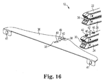
- FIG. 10 illustrates a method of attaching the stretch-fabric screen 18 to the frame members 22, 24, 26, 28.
- the stretch-fabric screen 18 preferably includes an outer peripheral flange 96 that is frictionally received within channels 98 extending along the length of the frame members 22, 24, 26, 28.
- a break in the peripheral flange 96 is provided at each middle hinge assembly 32 and at each corner hinge assembly 30 as illustrated.
- the flange 96 is preferably comprised of a plurality of elongated rectangular flange members 99 secured to the stretch fabric 18.
- the members 99 are preferably made of vinyl or other suitable material that it is lightweight, longitudinally flexible and resilient, yet somewhat rigid or stiff in the lateral direction.
- the stretch-fabric 18 may be secured to the flange members 99 by stitching, by adhesive, by providing pockets into which the flange members 99 are received or by any other suitable attaching method. As previously indicated, the flange sections 96 are frictionally received within the channels 98 so that the fabric screen 18 is securely yet removably secured to the frame 20.
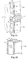
- FIGs. 21 and 22 illustrate an alternative embodiment for attaching the stretch-fabric screen 18 to frame members 128a and 128b.
- the stretch-fabric screen 18 includes a ridged peripheral flange 196 that is received within a mating channel 198 extending along the length of the frame members 128a, 128b.
- the ridged peripheral flange 196 is preferably made of vinyl or other suitable material that it is lightweight, longitudinally flexible and resilient, yet somewhat rigid or stiff in the lateral direction.
- the ridged flange 196 includes a ridged flange member 199 which has outwardly projecting ribs 194 positioned a distance from the flange end 195.
- the sidewalls 190 and 192 of the mating channel 198 include a mating recess 193 to receive the ribs 194. It should be appreciated that the width of the opening of the mating channel 198 is greater than the width of the flange end 195 but less than the width of the outwardly projecting ribs 194 of the flange member 199 so as to create an interference fit.
- the end portion 195 of the flange 196 is first inserted into the channels 198 temporarily holding the screen to the frame.
- the ridged flange 199 is then pressed into the mating recess 193 to securely seat the flange into the channel with an interference fit.
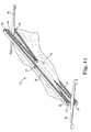
- FIG. 11 provides an exaggerated illustration of a preferred configuration of the frame 12 prior to attaching the stretch fabric screen 18. It should be appreciated that the greater the span between corner hinge assemblies and the tighter the stretch fabric 18 is stretched, the greater will be the tendency for the frame members to bow inwardly toward the middle of the span, resulting in the screen 18 being less taut toward the middle thereby distorting the projected image.
- the middle hinge assemblies 32 and corner hinge assemblies 30 are preferably configured to cant the frame members 22, 24, 26, 28 outwardly at the midpoints so that when the screen 18 is attached, the force exerted by the stretch-fabric 18 will pull the frame members inwardly to produce a more true parallelogram-shaped backwall with substantially square corners and substantially parallel opposing sides resulting in a substantially distortion free projected image. It should be appreciated that the amount of canting required for the frame members will vary depending on the size of the frame, the tautness of the screen 18, and the amount of play in the middle and corner hinge assemblies due to manufacturing tolerances.
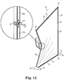
- FIGs. 12-20 illustrate the preferred steps for collapsing or folding the backwall 12.
- the vertical frame members 28a, 28b are unlocked by pulling the knob 88 on the middle hinge assembly 32 outwardly. The same operation is performed on the other vertical frame members 26a, 26b.
- the feet 34, 36 are removed from the backwall frame 20 as previously described.
- the top and bottom frame members 22, 24 are folded by pulling on the knobs 88 of the middle hinges 32 and bending the frame members 22a, 22b and 24a, 24b toward one another.
- the fully collapsed backwall 12 is illustrated in FIG. 20 .
Landscapes
- Physics & Mathematics (AREA)
- General Physics & Mathematics (AREA)
- Engineering & Computer Science (AREA)
- Theoretical Computer Science (AREA)
- Business, Economics & Management (AREA)
- Accounting & Taxation (AREA)
- Marketing (AREA)
- Overhead Projectors And Projection Screens (AREA)
Applications Claiming Priority (2)
| Application Number | Priority Date | Filing Date | Title |
|---|---|---|---|
| US16204609P | 2009-03-20 | 2009-03-20 | |
| US12/727,173 US8045264B2 (en) | 2009-03-20 | 2010-03-18 | Projection backwall apparatus and system |
Publications (1)
| Publication Number | Publication Date |
|---|---|
| EP2287827A1 true EP2287827A1 (fr) | 2011-02-23 |
Family
ID=42737358
Family Applications (1)
| Application Number | Title | Priority Date | Filing Date |
|---|---|---|---|
| EP10157053A Withdrawn EP2287827A1 (fr) | 2009-03-20 | 2010-03-19 | Appareil et système de face arrière de projection |
Country Status (3)
| Country | Link |
|---|---|
| US (1) | US8045264B2 (fr) |
| EP (1) | EP2287827A1 (fr) |
| CA (1) | CA2697195A1 (fr) |
Families Citing this family (29)
| Publication number | Priority date | Publication date | Assignee | Title |
|---|---|---|---|---|
| US9063405B2 (en) * | 2008-07-10 | 2015-06-23 | Open Air Cinema Llc | Blower noise muffler apparatus and system |
| WO2011094846A1 (fr) * | 2010-02-03 | 2011-08-11 | Visual Sports Systems | Enceinte pliante destinée à jouer à des jeux sur des ordinateurs et des consoles de jeu |
| EP2647619B1 (fr) | 2010-12-02 | 2015-01-21 | Ono Pharmaceutical Co., Ltd. | Nouveau composé et son utilisation médicale |
| WO2013066738A1 (fr) | 2011-11-03 | 2013-05-10 | Skyline Displays, Inc. | Systèmes et procédés d'affichage à cadre gonflable |
| CN202472230U (zh) * | 2012-03-07 | 2012-10-03 | 极品影视设备科技(深圳)有限公司 | 隐藏式投影幕 |
| ITVR20130125A1 (it) * | 2013-05-24 | 2014-11-25 | Screen Line Srl | Telaio per schermi per video proiezione |
| US9036257B2 (en) | 2013-05-31 | 2015-05-19 | Open Air Cinema Llc | Portable movie screens, systems, and methods of using the same |
| US9746761B2 (en) * | 2013-09-20 | 2017-08-29 | Five-Star Audiovisual, Inc. | Integrated furniture system for inconspicuously housing audiovisual equipment |
| ITVR20130289A1 (it) * | 2013-12-20 | 2015-06-21 | Screen Line Srl | Schermo per video proiezione |
| GB201405368D0 (en) * | 2014-03-25 | 2014-05-07 | Tekuchi Hong Kong Ltd | Portable display systems |
| CN108713161B (zh) * | 2016-02-11 | 2021-06-25 | 麦尔斯顿Av技术有限责任公司 | 折叠式投影屏幕 |
| KR102487905B1 (ko) * | 2016-03-31 | 2023-01-12 | 엘지전자 주식회사 | 프로젝터 장치 |
| US10139720B2 (en) * | 2016-05-11 | 2018-11-27 | Hisense Co., Ltd. | Projection system and projection screen supporting device |
| US10684173B2 (en) * | 2017-04-26 | 2020-06-16 | Marco Pinter | Interactive artistic presentation system with thermographic imagery |
| US10447946B2 (en) * | 2017-04-26 | 2019-10-15 | Marco Pinter | Interactive artistic presentation system with thermographic imagery |
| SE542870C2 (en) * | 2018-07-03 | 2020-07-21 | Kg Spennare Ab | Foldable frame for holding an image |
| EP3613618A1 (fr) * | 2018-08-23 | 2020-02-26 | REMIS Gesellschaft für Entwicklung und Vertrieb von technischen Elementen mbH Köln | Protection de protection contre les insectes pour une ouverture d'une unité de véhicule mobile |
| EP3690177B1 (fr) * | 2019-04-25 | 2021-04-28 | Büdenbender, Arnd | Raccord profilé à articulation rotative |
| EP3730310B1 (fr) * | 2019-04-25 | 2023-06-07 | Büdenbender, Arnd | Cadre à articulations tournantes |
| EP3835539B3 (fr) | 2019-12-13 | 2026-04-22 | Bash-tec GmbH | Kit pour un cadre |
| US11408224B2 (en) * | 2020-01-03 | 2022-08-09 | Pete De La Porte | Foldable door |
| USD928592S1 (en) * | 2020-07-08 | 2021-08-24 | Shenzhen Century-Star Audio & Visuals Co., Ltd | Frame element |
| USD914487S1 (en) * | 2020-07-08 | 2021-03-30 | Shenzhen Century-Star Audio & Visuals Co., Ltd | Frame element |
| USD936460S1 (en) * | 2020-07-08 | 2021-11-23 | Shenzhen Century-Star Audio & Visuals Co., Ltd | Frame element |
| USD919694S1 (en) * | 2020-09-13 | 2021-05-18 | Shenzhen Yaopengxin Trading Co., Ltd. | Projection screen |
| US11879250B2 (en) * | 2020-12-11 | 2024-01-23 | Awi Licensing Llc | Panel assembly for a suspended ceiling system, corner bracket thereof, and related methods |
| CN115644648A (zh) * | 2021-02-08 | 2023-01-31 | 金元安 | 一种展示框、基于矩形展示框的引线单元以及展示架 |
| DE102021134511B4 (de) * | 2021-12-23 | 2025-05-15 | Arnd Büdenbender | Bausatz für einen Rahmen und Profilverbinder |
| CN115641789B (zh) * | 2022-12-07 | 2026-01-13 | 常州灵特尔轻便展示系统有限公司 | 折叠展架 |
Citations (5)
| Publication number | Priority date | Publication date | Assignee | Title |
|---|---|---|---|---|
| FR2177155A5 (fr) * | 1972-03-21 | 1973-11-02 | Belzacq Freres Ets | |
| US6191886B1 (en) * | 1998-08-24 | 2001-02-20 | Vutec Corp. | Video projection screen assembly |
| WO2002097530A1 (fr) * | 2001-05-28 | 2002-12-05 | Lino Manfrotto + Co. S.P.A. | Cadre de support conçu pour des ecrans photographiques/cinematographiques |
| US20050200951A1 (en) * | 2004-03-10 | 2005-09-15 | Redmon Shanon O. | Lock for frame |
| US7337567B2 (en) * | 2004-12-01 | 2008-03-04 | Skyline Displays, Inc. | Retractable banner stand with curvature means |
Family Cites Families (39)
| Publication number | Priority date | Publication date | Assignee | Title |
|---|---|---|---|---|
| US1065402A (en) * | 1912-12-04 | 1913-06-24 | Waldo B Stearns | Curtain-stretcher. |
| US2631915A (en) * | 1950-12-01 | 1953-03-17 | Ivel Construction Corp | Combined folding display booth and transporting chest |
| US3300088A (en) * | 1964-11-27 | 1967-01-24 | Hickory Smoked Cheese Corp | Merchandising display with sample dispensing means |
| US3500569A (en) * | 1968-01-04 | 1970-03-17 | Dimensional Concepts Inc | Portable display unit |
| US3583466A (en) * | 1969-12-17 | 1971-06-08 | Polacoat Inc | Adjustable screen frame for rear projection screen or the like |
| US3987737A (en) * | 1973-03-15 | 1976-10-26 | Irving Smith | Collapsible display stand |
| US4017152A (en) * | 1975-05-14 | 1977-04-12 | Allen William P | Portable projection screen |
| US4110003A (en) * | 1975-12-27 | 1978-08-29 | Knox Manufacturing Company | Portable movie screen device |
| US4106852A (en) * | 1977-02-22 | 1978-08-15 | Producers Row Inc. | Projection screen support structure |
| US5125193A (en) * | 1990-12-03 | 1992-06-30 | Skyline Displays, Inc. | Foldable panel display system |
| US5271171A (en) * | 1992-02-10 | 1993-12-21 | Smith David C | Compressible and expandable stretching frame with adjustable corner brackets |
| DE9215330U1 (de) * | 1992-11-11 | 1992-12-24 | Geller, Peter, 2000 Hamburg | Transportabler Lichtreflektor |
| US5434631A (en) * | 1994-07-21 | 1995-07-18 | Lieberman; Phillip L. | Collapsible large screen audiovisual display system |
| US6012688A (en) * | 1996-10-28 | 2000-01-11 | Lamotte; Lester A. | Collapsible display system |
| US7185861B2 (en) * | 1996-10-28 | 2007-03-06 | Xtra Lite Display Systems, Inc. | Collapsible display system |
| US6122865A (en) * | 1997-03-13 | 2000-09-26 | Steelcase Development Inc. | Workspace display |
| GB9805198D0 (en) * | 1998-03-11 | 1998-05-06 | Maddock Alan | Portable visual display device |
| US6543164B1 (en) * | 2000-04-24 | 2003-04-08 | Skyline Displays, Inc. | Panel display system |
| US20020163720A1 (en) * | 2001-04-06 | 2002-11-07 | 3M Innovative Properties Company | Temporary screens and methods for displaying information |
| US6870670B2 (en) * | 2001-04-06 | 2005-03-22 | 3M Innovative Properties Company | Screens and methods for displaying information |
| WO2003104888A2 (fr) * | 2002-06-11 | 2003-12-18 | Av Stumpfl Usa Corp. | Ecran de projection mobile |
| AU2003251599A1 (en) * | 2002-06-21 | 2004-01-06 | Skyline Displays, Inc. | Framework connection system |
| US6785047B1 (en) * | 2002-12-20 | 2004-08-31 | Draper, Inc. | Tensioned projection screen apparatus |
| US6981350B1 (en) * | 2003-01-24 | 2006-01-03 | Draper, Inc. | Projection screen apparatus |
| US7316257B2 (en) * | 2003-03-25 | 2008-01-08 | Cameron Ronald A | Portable screen assembly |
| FR2857494B1 (fr) * | 2003-07-10 | 2005-09-02 | Atuser | Systeme d'affichage dynamique a ecrans numeriques amovibles interchangeables avec des affiches dans un boitier lumineux |
| JP2007537466A (ja) * | 2004-05-12 | 2007-12-20 | シラス・クリール | 折畳み式投影スクリーンシステム |
| US7396133B2 (en) * | 2004-12-06 | 2008-07-08 | N-Lighten Technologies | System and method for self-aligning collapsible display |
| US7236695B1 (en) * | 2004-12-22 | 2007-06-26 | Demos Nicholas S | Photographic backdrop with stand |
| US20060187544A1 (en) * | 2005-02-23 | 2006-08-24 | David Wiener | Flexible screen for front and rear projection |
| WO2007003012A1 (fr) * | 2005-07-05 | 2007-01-11 | Cineware Pty Ltd | Système audiovisuel |
| US7933068B2 (en) * | 2005-09-30 | 2011-04-26 | Seiko Epson Corporation | Reconfigurable projection-screen system |
| US7612938B2 (en) | 2006-02-14 | 2009-11-03 | Seiko Epson Corporation | Portable projection screen assembly |
| WO2008059345A2 (fr) | 2006-06-12 | 2008-05-22 | Maddock, Alan | Appareil d'écran pour affichage visuel |
| DE102006048473A1 (de) | 2006-10-11 | 2008-04-17 | Sefar Ag | Rückprojektionsgewebe, Rückprojektionsbildwand und Rückprojektionssystem |
| CA2616637A1 (fr) * | 2007-01-03 | 2008-07-03 | Skyline Displays, Inc. | Presentoir avec systeme de raccordement de banniere et banniere |
| TW200919075A (en) * | 2007-10-19 | 2009-05-01 | Bright View Technologies Inc | Portable front projection screen assemblies with flexible screens |
| US7872802B2 (en) * | 2008-08-29 | 2011-01-18 | Chris Seymour | Reinforced retractable projection screen with a tab tensioning system and a border |
| JP2010085640A (ja) * | 2008-09-30 | 2010-04-15 | Seiko Epson Corp | スクリーン |
-
2010
- 2010-03-18 US US12/727,173 patent/US8045264B2/en not_active Expired - Fee Related
- 2010-03-19 EP EP10157053A patent/EP2287827A1/fr not_active Withdrawn
- 2010-03-19 CA CA2697195A patent/CA2697195A1/fr not_active Abandoned
Patent Citations (5)
| Publication number | Priority date | Publication date | Assignee | Title |
|---|---|---|---|---|
| FR2177155A5 (fr) * | 1972-03-21 | 1973-11-02 | Belzacq Freres Ets | |
| US6191886B1 (en) * | 1998-08-24 | 2001-02-20 | Vutec Corp. | Video projection screen assembly |
| WO2002097530A1 (fr) * | 2001-05-28 | 2002-12-05 | Lino Manfrotto + Co. S.P.A. | Cadre de support conçu pour des ecrans photographiques/cinematographiques |
| US20050200951A1 (en) * | 2004-03-10 | 2005-09-15 | Redmon Shanon O. | Lock for frame |
| US7337567B2 (en) * | 2004-12-01 | 2008-03-04 | Skyline Displays, Inc. | Retractable banner stand with curvature means |
Also Published As
| Publication number | Publication date |
|---|---|
| US8045264B2 (en) | 2011-10-25 |
| US20100238544A1 (en) | 2010-09-23 |
| CA2697195A1 (fr) | 2010-09-20 |
Similar Documents
| Publication | Publication Date | Title |
|---|---|---|
| US8045264B2 (en) | Projection backwall apparatus and system | |
| JP3385207B2 (ja) | 可搬式スクリーン | |
| US20220026793A1 (en) | Lock for frame | |
| US6718669B1 (en) | Portable trade show exhibit system | |
| US7877914B2 (en) | Retractable banner stands with cooperating banners | |
| US10334972B2 (en) | Modular poster print stretch frame | |
| US6161320A (en) | Portable, modular, graphics-display system | |
| US7337567B2 (en) | Retractable banner stand with curvature means | |
| US4809471A (en) | Diagonal assembly for folding display frames | |
| US8468956B2 (en) | Collapsible transaction table | |
| US7886467B2 (en) | Portable sign frame assembly with changeable signage | |
| KR20170055977A (ko) | 시트 같은 재료의 연장 툴 | |
| US4727994A (en) | Collapsible support and attachment structure | |
| JP2019128579A (ja) | 映写スクリーン保持枠構造体 | |
| US10495122B2 (en) | Modular interlocking display systems | |
| US20200037758A1 (en) | Foldable cabinet | |
| US7140307B1 (en) | Display booth framework | |
| CN221300628U (zh) | 一种带抗风架结构的led显示屏模组 | |
| GB2310676A (en) | Plural height expandable framework; shipping case therefor convertible to podium | |
| CA2142569A1 (fr) | Systeme de retroprojection video a trajet de faisceau expose | |
| US20170011671A1 (en) | Collapsible display | |
| JP2009133879A (ja) | プロジェクタ・スタンド | |
| US8033041B2 (en) | Display panel tensioner and assemblies thereof | |
| JP7531896B2 (ja) | スタンド物品およびその構成部品 | |
| CN217690447U (zh) | 一种可折叠组装的宣传装置 |
Legal Events
| Date | Code | Title | Description |
|---|---|---|---|
| PUAI | Public reference made under article 153(3) epc to a published international application that has entered the european phase |
Free format text: ORIGINAL CODE: 0009012 |
|
| AK | Designated contracting states |
Kind code of ref document: A1 Designated state(s): AT BE BG CH CY CZ DE DK EE ES FI FR GB GR HR HU IE IS IT LI LT LU LV MC MK MT NL NO PL PT RO SE SI SK SM TR |
|
| AX | Request for extension of the european patent |
Extension state: AL BA ME RS |
|
| 17P | Request for examination filed |
Effective date: 20110812 |
|
| 17Q | First examination report despatched |
Effective date: 20120706 |
|
| STAA | Information on the status of an ep patent application or granted ep patent |
Free format text: STATUS: THE APPLICATION IS DEEMED TO BE WITHDRAWN |
|
| 18D | Application deemed to be withdrawn |
Effective date: 20141001 |