EP2287965A1 - Filtre à cavité coaxiale à couplage transversal en ligne - Google Patents
Filtre à cavité coaxiale à couplage transversal en ligne Download PDFInfo
- Publication number
- EP2287965A1 EP2287965A1 EP10171274A EP10171274A EP2287965A1 EP 2287965 A1 EP2287965 A1 EP 2287965A1 EP 10171274 A EP10171274 A EP 10171274A EP 10171274 A EP10171274 A EP 10171274A EP 2287965 A1 EP2287965 A1 EP 2287965A1
- Authority
- EP
- European Patent Office
- Prior art keywords
- resonators
- resonator
- bandpass filter
- plate
- filter
- Prior art date
- Legal status (The legal status is an assumption and is not a legal conclusion. Google has not performed a legal analysis and makes no representation as to the accuracy of the status listed.)
- Granted
Links
Images










Classifications
-
- H—ELECTRICITY
- H01—ELECTRIC ELEMENTS
- H01P—WAVEGUIDES; RESONATORS, LINES, OR OTHER DEVICES OF THE WAVEGUIDE TYPE
- H01P1/00—Auxiliary devices
- H01P1/20—Frequency-selective devices, e.g. filters
- H01P1/201—Filters for transverse electromagnetic waves
- H01P1/205—Comb or interdigital filters; Cascaded coaxial cavities
-
- H—ELECTRICITY
- H01—ELECTRIC ELEMENTS
- H01P—WAVEGUIDES; RESONATORS, LINES, OR OTHER DEVICES OF THE WAVEGUIDE TYPE
- H01P1/00—Auxiliary devices
- H01P1/20—Frequency-selective devices, e.g. filters
- H01P1/207—Hollow waveguide filters
- H01P1/208—Cascaded cavities; Cascaded resonators inside a hollow waveguide structure
- H01P1/2084—Cascaded cavities; Cascaded resonators inside a hollow waveguide structure with dielectric resonators
Definitions
- the described embodiments relate to microwave bandpass filters. More particularly, the described embodiments relate to inline cross-coupled microwave bandpass filters.
- transmission zeros on one or both sides of the passband are frequently required in order to meet rejection requirements.
- Transmission zeros are often realized by couplings between non-adjacent resonators, often referred to as cross couplings.
- Folded structures are often used to realize couplings between non-adjacent resonators. However, folded structures may not be suitable where there are structural constraints that require an inline configuration and/or input and output connectors on opposite sides of the two end resonators.
- FIG. 1A an inline cross-coupled microwave bandpass filter 100 in accordance with the prior art is illustrated.
- the filter 100 includes a housing 102, six cavities 104a to 104f, six resonators 106a to 106f situated in the cavities 104a to 104f, an input port 108 extending into the first cavity 104a, and an output port 110 extending into to the sixth cavity 104f.
- the filter 100 also includes a coupling probe 112 extending into the first and third cavities 104a and 104c to realize coupling between the first and third resonators 106a and 106c.
- a long coupling probe 112 generates unwanted resonances.
- FIG. 1B the frequency response of the bandpass filter 100 of FIG. 1A centered at 1.54 GHz is illustrated. It can be seen from FIG. 1B that in addition to generating a transmission zero 130 in the upper stop band, the coupling probe 112 resonates and generates a spike 132 in the lower stop band. Other disadvantages for such filters include the difficulty of tuning the cross-coupling.
- Embodiments described herein relate to inline microwave bandpass filters where cross couplings between non-adjacent resonators is realized by changing the orientation of selected resonators.
- a microwave bandpass filter comprising: (a) a cavity defined by a tubular structure and two opposing end walls, the tubular structure having a first end and a second end, one of the opposing end walls being attached to the first end and the other of the opposing end walls being attached to the second end; (b) at least three resonators arranged in a row in the cavity, connected by apertures, wherein at least one resonator has a different spatial orientation from at least one other resonator; (c) an input connector coupled to a first resonator of the at least three resonators; and (d) an output connector coupled to a second resonator of the at least three resonators.
- Such a microwave bandpass filter facilitates sequential coupling between pairs of adjacent resonators and cross coupling between at least one pair of non-adjacent resonators without the use of additional cross coupling structures such as dedicated coupling probes or extra cavities.
- Embodiments described herein relate to inline bandpass filters where cross couplings between non-adjacent resonators is realized by changing the orientation of selected resonators. For example, one or more of the resonators may be rotated 90 degrees or 180 degrees with respect to one or more of the resonators. In some embodiments, plates are introduced between adjacent resonators to control the sequential couplings between the adjacent resonators.
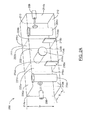
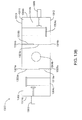
- FIG. 2A is a perspective view of the bandpass filter 200
- FIG. 2B is a side view of the bandpass filter 200
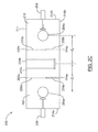
- FIG. 2C is a top view of the bandpass filter 200.
- the bandpass filter 200 includes a cavity 202 , three resonators 204a, 204b , and 204c arranged in a row in the cavity 202 , an input connector 206 connected to the first resonator 204a , and an output connector 208 connected to the third resonator 204c.
- the input and output connectors 206 and 208 are shown in FIGS. 2A to 2C as being connected to the first and third resonators 204a and 204c , the input and output connectors 206 and 208 may be connected to any of the resonators.
- the cavity 202 is defined by a tubular structure 211 and two opposing end walls 214a and 214b attached to either end of the tubular structure 211 .
- the tubular structure 211 has a rectangular shape, and is defined by a top wall or lid 210 (which may be removable), a bottom wall 212 , and two opposing side walls 216a and 216b that extend between the top wall 210 and the bottom wall 212 .
- the cavity 202 has a width a and a height b ( FIG. 2A ).
- the tubular structure has a cylindrical shape and is defined by a single continuous wall (not shown).
- the cavity walls 210, 212, 214a, 214b, 216a and 216b are typically made of a suitable metal such as aluminum or copper. However, the cavity walls 210, 212, 214a, 214b, 216a and 216b may be made of other suitable metals. Although the cavity walls 210, 212, 214a, 214b, 216a and 216b are typically translucent, for ease of explanation, the cavity walls 210, 212, 214a, 214b, 216a and 216b are shown in FIGS. 2A to 2C as being transparent.
- the three resonators 204a, 204b and 204c are arranged in a row or "inline" in the cavity. In inline filters, the centers of the resonators are aligned along the same longitudinal axis as opposed to, for example, filters with resonators arranged in two or more rows.
- the filter 200 is shown as having three resonators 204a, 204b , and 204c , filters in accordance with embodiments described herein may have three or more resonators. The number of resonators is typically selected based on the filter requirements.
- the resonators 204a, 204b and 204c are coaxial resonators with square or rectangular cavity cross-sections.
- the resonators 204a, 204b, and 204c may be any type of suitable coaxial resonator.
- the first and second resonators 204a and 204b are separated by a distance d 1
- the second and third resonators 204b and 204c are separated by a distance d 2 ( FIG. 2C ).
- the distance d 1 between the first and second resonators 204a and 204b may by the same as, or different than, the distance d 2 between the second and third resonators 204b and 204c.
- the distances d 1 d 2 between resonators are typically measured from the centre points of the resonators 204a, 204b and 204c.
- At least one of the resonators 204a, 204b , and 204c has a different spatial orientation from at least one other resonator.
- one or more of the resonators 204a, 204b, or 204c may be rotated between 1 degree and 360 degrees with respect to one of the other resonators 204a, 204b, or 204c .
- one or more resonators 204a, 204b and 204c is rotated 90 degrees or 180 degrees from one of the other resonators.
- the second resonator 204b is rotated with respect to the first and third resonators 204a and 204c so that the second resonator 204b has a different orientation from the first and third resonators 204a and 204c .
- the second resonator 204b may be rotated 90 degrees with respect to the first and third resonators 204a and 204c so that the first and third resonators 204a and 204c are substantially vertical and the second resonator 204b is substantially horizontal.
- the third resonator is also rotated with respect to the first resonator so that both the second and third resonators have different orientations from the first resonator.
- the third resonator may be rotated 180 degrees with respect to the first resonator so that it can be said to be is upside down with respect to the first resonator.
- the filter 200 of FIGS, 2A to 2C not only realizes sequential coupling between adjacent resonators (e.g. between first and second resonators 204a and 204b , and second and third resonators 204b and 204c ), but it also realizes cross coupling between at least one pair of non-adjacent resonators (e.g. between first and third resonators 204a and 204c ).
- the cross coupling is achieved without the use of additional cross coupling structures such as dedicated coupling probes or extra cavities.
- Each cross coupling (coupling between non-adjacent resonators) creates a transmission zero in the upper or lower stop band, or both.
- the cross coupling between the first and third resonators 204a and 204c produces a transmission zero in the upper stop band.
- the second resonator 204b is rotated 90 degrees with respect to the first resonator 204a
- the third resonator 204c is rotated 180 degrees with respect to the first resonator 204a, as shown in FIGS. 13A to 13C
- the cross coupling between the first and third resonators 204a and 204c produces a transmission zero in the lower stop band.
- Additional resonators may be added to the filter 200 to increase the number of cross couplings or the number of transmission zeros, or both.
- a filter having four resonators where the second and third resonators are rotated 90 degrees with respect to the first resonator (i.e. the first resonator is substantially vertical and the second and third resonators are substantially horizontal), and the fourth resonator is rotated 180 degrees with respect to the first resonator (i.e. the fourth resonator is upside down), will realize cross coupling between the first and fourth resonators that produces a pair of transmission zeros, one in the lower stop band and one in the upper stop band.
- first and second resonators 204a and 204b in this configuration is dominantly magnetic coupling
- rotation of the second resonator 204b by 90 degrees makes the inter-resonator coupling less effective compared to known combline configurations, which allows for a more compact design.
- the resonators 204a, 204b, and 204c can be placed closer together.
- the bandpass filter 200 may also include one or more plates 218a and 218b situated between adjacent resonators (e.g. first and second resonators 204a and 204b, or second and third resonators 204b and 204c) to allow independent control of the sequential and cross coupling. Specifically, by proper arrangement of the location and size of the plates 218a and 218b and the distance between resonators, the desired sequential and cross coupling coefficients can be realized.
- bandpass filter 200 is shown with only a single plate 218a and 218b between any pair of adjacent resonators, in other embodiments, there may be more than one plate between a pair of adjacent resonators.
- the plates 218a and 218b are rectangular metal walls with a height H and length L. In some cases, the height H and the length L of the plates 218a and 218b are the same so that the plates are square. However, the plates 218a and 218b may have other suitable shapes and sizes. Preferably the plates 218a and 218b are made of the same materials as the cavity walls 210, 212, 214a, 214b , 216a and 216b (i.e. aluminum or copper). However, the plates 218a and 218b may be made of other suitable materials. In some embodiments, the plates 218a and 218b are machined as part of the cavity walls 212, 214a, 214b, 216a, 216b and 210 .
- Each plate 218a and 218b is typically situated within a plane 220a or 220b that is substantially parallel to the end walls 214a and 214b so that each plate 218a and 218b is substantially parallel to the end walls 214a and 214b.
- Each plane 220a and 220b is defined by an upper left-corner 222a, 222b, an upper right-corner 224a, 224b , a lower left corner 226a, 226b and a lower right corner 228a, 228b .
- the upper left-corner 222a, 222b is the corner of the plane 220a, 220b formed by the first side wall 216a and the lid 210
- the upper right-corner 224a, 224b is the corner of the plane 220a, 220b formed by the second side wall 216b and the lid 210
- the lower left corner 226a, 226b is the corner of the plane 220a, 220b formed by the first side wall 216a and the bottom wall 212
- the lower right corner 228a, 228b is the corner of the plane 220a, 220b formed by the second side wall 216b and the bottom wall 212
- Each plate 218a and 218b is typically situated in one corner 222a, 224a, 226a and 228a or 222b, 224b, 226b, and 228b of a plane 220a or 220b .
- FIGS. 3A and 3B illustrate a plate 218 in the lower-left corner 226 and the lower right corner 228 of a plane 220 respectively.
- Increasing the size of the plate when it is positioned in some of the corners will increase the sequential coupling coefficient, and increasing the plate size when it is positioned in other corners will decrease the sequential coupling coefficient.
- the corners which result in an increase in the sequential coupling coefficient will be referred to as increase positions, and the corners which result in a decrease in the sequential coupling coefficient will be referred to as decrease positions.
- the determination of which corners act as increase positions and which corners act as decrease positions depends on (1) the orientation of the resonators on either side of the plate, and (2) the size of the plate. This means that a corner may change from being a decrease position to an increase position as the size of the plate changes. For example, some corners may be decrease positions when the plate size is less than a threshold value, and increase positions when the plate size is greater than the threshold value.
- Each plane 220a and 220b (and incidentally each plate 218a and 218b) is typically situated at the mid-point between adjacent resonators (e.g. at the mid-point between the first and second resonators 204a and 204b, or at the mid-point between the second and third resonators 204b and 204c). However, the planes 220a and 220b may be situated at any point between adjacent resonators.
- the filter 200 may also include sequential coupling and/or cross coupling tuning elements (not shown).
- filter 200 may include tuning screws situated on one or more cavity walls 210, 212, 214a, 214b, 216a and 216b .
- the position of the tuning screws on the cavity walls is typically based on the orientation of the resonators within the cavity 202.
- tuning screws may be placed on the lid 210 or the bottom wall 212 between cross coupled resonators (e.g. between first and third resonators 204a and 204c) to facilitate tuning of the cross coupling.
- Filter 200 may also include tuning screws placed on one of the side walls 216a or 216b between adjacent resonators (e.g. between first and second resonators 204a and 204b and between second and third resonators 204b and 204c) for adjusting the sequential coupling. Accordingly, all sequential and cross couplings can be effectively adjusted.
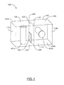
- FIG. 4 illustrates a two-coupled resonator structure 400 for eigenmode calculation.
- the two-coupled resonator structure 400 has the same configuration as the bandpass filter 200 of FIGS, 2A to 2C except it comprises only two resonators 404a and 404b and it does not include input and output connectors.
- Elements of the two-coupled resonator structure 400 that correspond to microwave bandpass filter 200 will be identified by similar reference numerals. Generally, corresponding elements will share the same last two digits.
- the cavity 202 of the filter 200 of FIGS. 2A to 2C corresponds to the cavity 402 of the resonator structure 400 of FIG. 4 .
- the first resonator 404a of resonator structure 400 has a substantially vertical orientation
- the second resonator 404b of resonator structure 400 has a substantially horizontal orientation. Accordingly, it can be said that the second resonator 404b is rotated 90 degrees with respect to the first resonator 404a.
- equation (1) can be used to calculate the coupling coefficient k where f 1 and f 2 are the two eigenmodes of the resonator structure 400 of FIG. 4 .
- the two eigenmodes ( f 1 and f 2 ) can be calculated using the eigenmode solver of an electromagnetic (EM) field simulator, such as Ansoft Corporation's HFSSTM.
- EM electromagnetic
- FIGS. 5A to 5C illustrate the sequential coupling coefficient for the resonator structure 400 of FIG. 4 as a function of the length (or height) of the square plate 418 when the cavity 402 width and height are both 1.5 inches, both resonators 404a and 404b have a diameter of 0.4 inches and a height of 1.3 inches, the distance between the first resonator 404a and the first end wall 414a is 0.75 inches and the distance between the second resonator 404b and the second end wall 414b is 0.75 inches.
- FIGS. 5A to 5C illustrates the sequential coupling coefficient for the resonant structure 400 of FIG.
- FIG. 5A illustrates the sequential coupling coefficient for the resonator structure 400 of FIG. 4 when the plate 418 is positioned in the bottom-left corner 426 of the plane 420
- FIG. 5B illustrates the sequential coupling coefficient for the resonant structure 400 of FIG. 4 when the plate 418 is positioned in the bottom-right corner 428 of the plane 420
- FIG. 5C illustrates the sequential coupling coefficient for the resonator structure 400 of FIG. 4 when the plate 418 is positioned in the upper-right corner 424 of the plane 420.
- FIG. 5A includes three coupling coefficient curves 502, 504, and 506 illustrating the sequential coupling coefficient when the plate 418 is positioned in the bottom left corner 426 of the plane 420 and the resonators 404a and 404b are separated by distances of 1.3 inches, 1.2 inches, and 1.1 inches respectively. It is clear from the three coupling coefficient curves 502, 504 and 506 that, regardless of the distance between the resonators 404a and 404b, when the plate 418 is positioned in the bottom left corner 426 of the plane 420 the sequential coupling coefficient decreases as the length (or height) of the square plate 418 increases. Accordingly, when the resonators are oriented in the manner shown in FIG.
- the plate 418 reduces the magnetic coupling between the resonators 404a and 404b and thus reduces the total coupling. It can be seen from FIG. 5A , that the sequential coupling coefficient reduces to zero when the length of the plate 418 is about half of the resonator height (e.g. ⁇ 0.65 inches when the resonator height is 1.3 inches). After this point, the coupling changes from magnetic coupling to electric coupling and the total coupling begins to increase.
- FIG. 5B includes three coupling coefficient curves 508, 510, and 512 illustrating the sequential coupling coefficient when the plate 418 is positioned in the bottom right corner 428 of the plane 420 and the resonators 404a and 404b are separated by distances of 1.3 inches, 1.2 inches, and 1.1 inches respectively. It is clear from the three coupling coefficient curves 508, 510 and 512 of FIG. 5B that, regardless of the distance between the resonators 404a and 404b, when the plate 418 is positioned in the bottom right corner 428 of the plane 420, the sequential coupling coefficient increases as the length of the plate 418 increases. Accordingly, when the resonators are oriented in the manner shown in FIG.
- the first resonator 404a is substantially vertical and the second resonator 404b is substantially horizontal - the bottom right corner 428 is an increase position as that term was defined above.
- the plate 418 reduces the electric coupling between the resonators 404a and 404b and thus increases the total coupling.
- a plate 418 positioned in the upper-left corner 422 has the same effect on the sequential coupling coefficient as a plate positioned in the bottom right corner 428.
- FIG. 5C includes three coupling coefficient curves 514, 516, and 518 illustrating the sequential coupling coefficient when the plate 418 is positioned in the upper-right corner 424 of the plane 420 and the resonators 404a and 404b are separated by distances of 1.3 inches, 1.2 inches, and 1.1 inches respectively. It is clear from the three coupling coefficient curves 514, 516, and 618 that, regardless of the distance between the resonators 404a and 404b, when the plate 418 is positioned in the upper-right corner 424 of the plane 420, the sequential coupling coefficient decreases as the length of the plate 418 increases until the length of the plate 418 is roughly equal to half of the resonator height (e.g.
- the sequential coupling coefficient increases as the length of the plate increases. This is because when the plate 418 is positioned in the upper-right corner 424 increasing the length of the plate 418 increases the electric coupling.
- the coupling is magnetic coupling therefore as the electric coupling increases, the total coupling decreases.
- the coupling changes to electric coupling and thus increasing the electric coupling, increases the total coupling.
- the first resonator 404a is substantially vertical and the second resonator 404b is substantially horizontal - the upper-right corner 424 is a decrease position when the length (or height) of the square plate 418 is less than half of the resonator height, and an increase position when the length (or height) or the square plate 418 is greater than half of the resonator height.
- FIGS. 5A to 5C also illustrate that, regardless of the position and the size of the plate, the sequential coupling coefficient decreases as the distance d between resonators 404a and 404b increases.
- Changing the thickness of the plate 418 has a similar effect on the sequential coupling as changing the length (or height) of the plate 418. For example, when the plate 418 is positioned in the bottom left corner 426 of the plane 420, the sequential coupling coefficient decreases as the thickness of the plate 418 increases. In some embodiments, the plate 418 has a thickness of 0.04 inches. However, the plate 418 may have any suitable thickness.
- the sequential coupling between adjacent resonators can be effectively controlled by changing (i) the size of the plate 418; (ii) the position of the plate 418; and (iii) the distance d between the resonators 404a and 404b.
- the sequential coupling can be significantly increased.
- the same sequential coupling can be realized with different combinations of resonator distance, plate size, and plate location. Each of the combinations will result in different cross couplings.
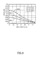
- FIG. 6 illustrates the cross coupling coefficient for filter 200 of FIGS. 2A to 2C as a function of the length of the plates 218a and 218b when the plates 218a and 218b are positioned in the lower-left corner 226a and 226b of the respective planes 220a and 220b.
- FIG. 6 includes three cross coupling coefficient curves 602, 604 and 606 illustrating the cross coupling coefficient when adjacent resonators (i.e.
- the first and second resonators 204a and 204b, and second and third resonators 204b and 204c) are separated by a distance of 1.3 inches, 1.2 inches and 1.1 inches respectively. It can be seen from the three curves 602, 604, and 606 of FIG. 6 that the cross coupling coefficient reduces monotonically as the size of the plate increases and as the resonator distance increases. If the plates 218a and 218b are moved to the lower-right corner 228a and 228b of the respective planes 220a and 220b, the cross coupling coefficient curves are similar to the three curves 602, 604 and 606 of FIG. 6 .
- FIG. 7 illustrates the cross coupling coefficient for filter 200 of FIGS, 2A to 2C as a function of the length of the plates 218a and 218b when the plates 218a and 218b are positioned in the top-left corner 222a and 222b of the respective planes 220a and 220b.
- FIG. 7 includes three cross coupling coefficient curves 702, 704 and 706 illustrating the cross coupling coefficient when adjacent resonators (i.e. the first and second resonators 204a and 204b, and second and third resonators 204b and 204c) are separated by a distance of 1.3 inches, 1.2 inches and 1.1 inches respectively.
- the cross coupling coefficient reduces monotonically as the size of the plate increases and as the resonator distance increases. If the plates 218a and 218b are moved to the top-right corner 224a and 224b of the respective planes 220a and 220b, the cross coupling coefficient curves are similar to the three curves 702, 704 and 706 of FIG. 7 .
- the nonadjacent or cross coupling between non adjacent resonators may be calculated by detuning the second resonator 204b of FIGS. 2A to 2C , removing the input/output ports, finding the two resonant frequencies using the eigenmode solver of an EM field simulator, such as Ansoft Corporation's HFSSTM, and then using equation (1) to calculate the cross coupling coefficient.
- an EM field simulator such as Ansoft Corporation's HFSSTM
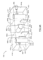
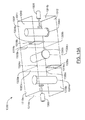
- FIGS. 8A to 8C An exemplary filter 800 with multiple plates between adjacent resonators is shown in FIGS. 8A to 8C .
- FIG. 8A is a perspective view of the bandpass filter 800
- FIG. 8B is a side view of the bandpass filter 800
- FIG. 8C is a top view of the bandpass filter 800.
- Bandpass filter 800 has the same configuration as bandpass filter 200 of FIGS. 2A to 2C except that it has four rectangular plates 818a, 818b, 818c and 818d, two between each pair of adjacent resonators. Elements of microwave bandpass filter 800 that correspond to microwave bandpass filter 200 of FIGS.
- the cavity 202 of the filter 200 of FIGS, 2A to 2C corresponds to the cavity 802 of the filter 800 of FIGS. 8A to 8C .
- two of the rectangular plates 818c and 818d are positioned at the lower-left corner 826a and 826b of the corresponding planes 820a and 820b, and two of the rectangular plates 818a and 818b are positioned in the lower-right corner 828a and 828b of the corresponding planes 820a and 820b.
- Each of the plates 818c and 818d in the lower-left corner 826a, 826b has a length of L A and height of L.
- Each of the plates 818a and 818b in the lower-right corner 828a, 828b has a length of L B and height of L.
- the sequential coupling between adjacent resonators i.e. between the first and second resonators 804a and 804b, or between the second and third resonators 804b and 804c
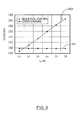
- cross coupling between the first and third resonators 804a and 804c is a function of L B as shown in FIG 9 .
- the filter 800 of FIGS. 8A to 8C and the filter 200 of FIGS. 2A to 2C have the same configuration.
- the filter 800 of FIGS. 8A to 8C can therefore be considered as the result of splitting the plates 218a and 218b in FIGS. 2A to 2C into two pieces.
- the cross coupling remains unchanged and sequential coupling increases when the length L B of the plates 818a and 818b in the lower-right corner 828a, 828b increases. Therefore, by separating the plate into two pieces, the sequential coupling and cross coupling can be controlled independently. In particular, making one piece smaller and the other piece bigger does not change cross coupling, but changes sequential coupling significantly.
- a filter may be designed following these general steps.
- the initial values for resonator distance, position and sizes of the coupling plate(s) are estimated using the curves shown in FIGS. 5A, 5B, 5C , 6 and 7 through interpolation. Understandably, if the filter center frequency, cavity size, or resonator sizes are different from the examples herein, new curves of sequential and cross coupling values need to be calculated. These initial dimensions are then optimized using conventional methods to meet the desired filter performance.
- the size of the plate(s) can be selected to realize the required cross coupling value using FIG. 6 or FIG. 7 as if a single plate is to be used. Then, it is decided how the plate can be split to realize the desired sequential coupling through direct calculation of the sequential coupling or data curves similar to FIG. 9 . These initial dimensions are then optimized using conventional methods to meet the desired filter performance. Using multiple coupling plates between adjacent resonators offers additional design flexibility.
- each of the four filters described below have been designed to have a center frequency of 1.54 GHz and a bandwidth of 48.8 MHz.
- the cavity width a is 1.5 inches
- the cavity height b is 1.5 inches
- the thickness of each plate is 0.04 inches
- the diameter of each resonator is 0.4 inches
- the height of each resonator is 1.3 inches.
- the first exemplary filter is the filter 200 of FIGS. 2A to 2C where the distance between adjacent resonators is 1.3 inches; the length and height of the plates 218a and 218b is 0.6 inches; the distance between the first resonator 204a and the first end wall 214a is 0.75 inches; and the distance between the third resonator 204c and the second end wall 214b is 0.75 inches.
- the second exemplary filter is the filter 800 of FIGS. 8A to 8C where the distance between adjacent resonators is 1.25 inches, the height of the plates 818a, 818b, 818c and 818d is 0.7 inches; the length of the plates 818c and 818d is 0.18 inches; the length of the plates 818a and 818b is 0.55 inches; the distance between the first resonator 804a and the first end wall 814a is 0.75 inches; and the distance between the third resonator 804c and the second end wall 814b is 0.75 inches.
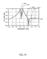
- FIG. 10 illustrates the frequency response of both the first and the second exemplary filters.
- FIG. 10 illustrates the simulated S 11 and S 21 scattering parameter ("s-parameter") curves 1002 and 1004 for the first exemplary filter, and the simulated S 11 and S 21 s-parameter curves 1010 and 1012 for the second exemplary filter.
- the first exemplary filter is a three pole filter with a transmission zero 1006 in the upper stop band.
- the transmission zero 1006 is generated by the cross coupling between the first and third resonators 204a and 204c.
- the second exemplary filter realizes the same sequential and cross coupling values as the first exemplary filter using multiple plates between adjacent resonators.
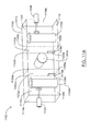
- the third exemplary filter is filter 1100 illustrated in FIGS. 11A and 11 B where the distance between adjacent resonators is 1.1 inches; the plates 1118a and 1118b have a length and height of 0.3 inches; the distance between the first resonator 1104a and the first end wall 1114a is 0.75 inches; and the distance between the third resonator 1104c and the second end wall 1114b is 0.75 inches.
- FIG. 11A is a perspective view of the bandpass filter 1100
- FIG. 11 B is a top view of the bandpass filter 1100.
- Bandpass filter 1100 has the same configuration as bandpass filter 200 of FIGS. 2A to 2C except that the plates 1118a and 1118b are positioned in different corners of the planes 1120a and 1120b.
- the first and second plates 1118a and 1118b are placed in the lower-left corners 1126a and 1126b of the first and second planes 1120a and 1120b respectively.
- Elements of microwave bandpass filter 1100 that correspond to microwave bandpass filter 200 of FIGS. 2A to 2C will be identified by similar reference numerals. Generally, corresponding elements will share the same last two digits.
- the cavity 202 of the filter 200 of FIGS. 2A to 2C corresponds to the cavity 1102 of the filter 1100 of FIGS, 11A and 11B .
- FIG. 12 illustrates the frequency response of the third exemplary filter.
- FIG. 12 illustrates the simulated S 11 and S 21 scattering parameter ("s-parameter") curves 1202 and 1204 for the third exemplary filter.
- s-parameter scattering parameter
- the third exemplary filter is also a three-pole filter with a transmission zero 1206 in the upper stop band.
- the third exemplary filter achieves the same bandwidth as the first exemplary filter using a different resonator distance, plate size and plate location, resulting in a different out-of-band rejection level.
- the transmission zero 1206 of FIG. 12 is closer to the passband than the transmission zero 1006 of FIG. 10 .
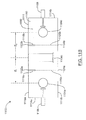
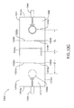
- the fourth exemplary filter is the bandpass filter 1300 of FIGS. 13A to 13C where the distance between adjacent resonators is 1.27 inches; the length and height of the plates 1318a and 1318b is 0.6 inches; the distance between the first resonator 1304a and the first end wall 1314a is 0.75 inches; and the distance between the third resonator 1304c and the second end wall 1314b is 0.75 inches.
- FIG. 13A is a perspective view of the bandpass filter 1300
- FIG. 13B is a side view of the bandpass filter 1300
- FIG. 13C is a top view of the bandpass filter 1300.
- Bandpass filter 1300 has the same configuration as the bandpass filter 200 of FIGS.
- the plates 1318a and 1318b are positioned in different corners of the planes 1320a and 1320b. Specifically, the first plate 1318a is positioned in the lower-right corner 1328a of the first plane 1320a, and the second plate 1318b is positioned in the upper-right corner 1324b of the second plane 1320b.
- Elements of microwave bandpass filter 1300 that correspond to microwave bandpass filter 200 will be identified by similar reference numerals. Generally, corresponding elements will share the same last two digits.
- the cavity 202 of the filter 200 of FIGS. 2A to 2C corresponds to the cavity 1302 of the filter 1300 of FIGS. 13A to 13C .
- both the second and third resonators 1304b and 1304c have a different spatial orientation than the first resonator 1304a. Similar to the filter 200 of FIGS. 2A to 2C , the second resonator 1304b is rotated 90 degrees with respect to the first resonator 1304a so that the first resonator 1304a is substantially vertical and the second resonator 1304b is substantially vertical. However, unlike the filter 200 of FIGS. 2A to 2C , the third resonator 1304c is also rotated with respect to the first resonator 1304a.
- the third resonator 1304c is rotated 180 degrees with respect to the first resonator 1304a so that the third resonator 1304c is upside down with respect to the first resonator 1304a. As described above, this results in cross coupling between the first and third resonators 1304a and 1304c that produces a transmission zero in the lower stop band of the frequency response of the filter.
- the first plate 1318a of filter 1300 is positioned in the lower-right corner 1328a of the first plane 1320a.
- the second plate 1318b of filter 1300 is positioned in the upper-right corner 1324b of the second plane 1320b. It should be noted that because of the orientation of the second and third resonators 1304b and 1304c the second plate 1318b of filter 1300 (although situated in a different corner) will have the same effect on the second and third resonators 1304b and 1304c of filter 1300 as the second plate 218b will have on the second and third resonators 204b and 204c of filter 200.
- both the second plate 1318b of filter 1300 and the second plate 218b of filter 200 are situated in the corner that is closest to the top of the corresponding second resonator 204b, 1304b and the bottom of the corresponding third resonator 204c, 1304c.
- FIG. 14 illustrates the frequency response of the fourth exemplary filter.
- FIG. 14 illustrates the simulated S 11 and S 21 scattering parameter ("s-parameter") curves 1402 and 1404 for the fourth exemplary filter, It can be seen from the s-parameter curves 1402 and 1404 that the fourth exemplary filter is a three-pole filter with a transmission zero 1406 below its passband.
- s-parameter scattering parameter
- the fifth exemplary filter is the bandpass filter 1500 of FIG. 15 where the distance between resonators is 1.12 inches between the first and second resonators 1504a and 1504b, 1.1 inches between the second and third resonators 1504b and 1504c, 1.5 inches between the third and fourth resonators 1504c and 1504d, 1.35 inches between the fourth and fifth resonators 1604d and 1504e, 1.2 inches between the fifth and sixth resonators 1504e and 1504f; and the first plate 1518a has a length and height of 0.48 inches, the second plate 1518b has a length and height of 0.38 inches, and the third plate 1518c has a length and height of 0.475 inches.
- the distance between the first resonator 1504a and the first end wall 1514a is 0.75 inches.
- the distance between the sixth resonator 1504f and the second end wall 1514b is 0.75 inches.
- Bandpass filter 1500 has the same configuration as the bandpass filter 200 of FIGS. 2A to 2C except it includes three additional resonators 1504d, 1504e and 1504f.
- the fourth and sixth resonators 1504d and 1504f similar to the first and third resonators 1504a and 1504c , have a substantially vertical orientation
- the fifth resonator 1504e similar to the second resonator 1504b, has a substantially horizontal orientation. Accordingly, filter 1500 will have two transmission zeros in the upper stop band. The first transmission zero is produced by the cross coupling between the first and third resonators 1504a and 1504c
- the second transmission zero is produced by the cross coupling between the fourth and sixth resonators 1504d and 1504f.
- bandpass filter 1500 has a different configuration of plates over filter 200. Specifically, bandpass filter 1500 has three plates 1518a, 1518b, and 1518c.
- the first plate 1518a is situated between the second and third resonators 1504b and 1504c in the lower-left corner of the first plane 1520a.
- the second plate 1518b is situated between the fourth and fifth resonators 1504d and 1504e in the lower-right corner of the second plane 1520b.
- the third plate 1518c is situated between the fifth and sixth resonators 1504e and 1504f in the lower-right corner of the third plane 1520c.
- Bandpass filter 1500 also has a metal wall 1550 between the third and fourth resonators 1504c and 1504d. Such wall is a well-known conventional way of controlling the sequential coupling between the third and the fourth resonators 1504c and 1504d. In the fifth exemplary filter the wall 1550 has a height of 0.815 inches.
- microwave bandpass filter 1500 that correspond to microwave bandpass filter 200 are identified by similar reference numerals. Generally, corresponding elements will share the same last two digits.
- the cavity 202 of the filter 200 of FIGS. 2A to 2C corresponds to the cavity 1502 of the filter 1500 of FIGS. 15 .
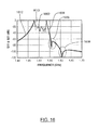
- FIG. 16 illustrates the frequency response of the fifth exemplary filter.
- FIG. 16 illustrates the measured S 11 and S 21 scattering parameter ("s-parameter") curves 1602 and 1604 and the simulated S 11 and S 21 curves 1610 and 1612 for the fifth exemplary filter. It can be seen from the s-parameter curves 1602, 1604, 1610 and 1612 that the fifth exemplary filter is a six-pole filter with two transmission zeros 1606 and 1608 in the upper stop band.
- s-parameter scattering parameter
Landscapes
- Physics & Mathematics (AREA)
- Electromagnetism (AREA)
- Control Of Motors That Do Not Use Commutators (AREA)
Applications Claiming Priority (1)
| Application Number | Priority Date | Filing Date | Title |
|---|---|---|---|
| US12/533,488 US8085118B2 (en) | 2009-07-31 | 2009-07-31 | Inline cross-coupled coaxial cavity filter |
Publications (2)
| Publication Number | Publication Date |
|---|---|
| EP2287965A1 true EP2287965A1 (fr) | 2011-02-23 |
| EP2287965B1 EP2287965B1 (fr) | 2013-04-03 |
Family
ID=43027604
Family Applications (1)
| Application Number | Title | Priority Date | Filing Date |
|---|---|---|---|
| EP10171274A Active EP2287965B1 (fr) | 2009-07-31 | 2010-07-29 | Filtre à cavité coaxiale à couplage transversal en ligne |
Country Status (2)
| Country | Link |
|---|---|
| US (1) | US8085118B2 (fr) |
| EP (1) | EP2287965B1 (fr) |
Cited By (1)
| Publication number | Priority date | Publication date | Assignee | Title |
|---|---|---|---|---|
| GB2478938A (en) * | 2010-03-24 | 2011-09-28 | Gary Raymond Cobb | Coupled transmission line resonator band-pass filter with transversely rotated resonators for improved selectivity |
Families Citing this family (7)
| Publication number | Priority date | Publication date | Assignee | Title |
|---|---|---|---|---|
| CN102496757A (zh) * | 2011-12-21 | 2012-06-13 | 京信通信系统(中国)有限公司 | 具有超宽频耦合端口的通信装置 |
| DE102012020576B4 (de) * | 2012-10-22 | 2018-02-15 | Tesat-Spacecom Gmbh & Co.Kg | Mikrowellenfilter mit einstellbarer Bandbreite |
| US9306258B2 (en) * | 2013-02-08 | 2016-04-05 | Ace Technologies Corporation | Mixed-mode cavity filter |
| US9509031B2 (en) * | 2013-05-23 | 2016-11-29 | Com Dev International Ltd. | Coaxial filter with elongated resonator |
| CN103474730B (zh) * | 2013-09-26 | 2015-04-22 | 西安空间无线电技术研究所 | 一种同轴输出滤波器的设计方法 |
| EP3485528A4 (fr) | 2016-07-18 | 2020-03-04 | CommScope Italy S.r.l. | Filtres en ligne tubulaires qui conviennent pour des applications cellulaires et procédés associés |
| RU2645033C1 (ru) * | 2017-04-05 | 2018-02-15 | Общество с ограниченной ответственностью Научно-производственное предприятие "НИКА-СВЧ" | СВЧ-мультиплексор |
Citations (5)
| Publication number | Priority date | Publication date | Assignee | Title |
|---|---|---|---|---|
| US5608363A (en) * | 1994-04-01 | 1997-03-04 | Com Dev Ltd. | Folded single mode dielectric resonator filter with cross couplings between non-sequential adjacent resonators and cross diagonal couplings between non-sequential contiguous resonators |
| EP1174944A2 (fr) * | 2000-07-17 | 2002-01-23 | Mitec Telecom Inc. | Filtre passe-bande accordable |
| US20030197577A1 (en) * | 2002-04-22 | 2003-10-23 | K&L Microwave, Inc. | Single port delay element |
| WO2005045985A1 (fr) * | 2003-10-08 | 2005-05-19 | M/A-Com, Inc. | Filtre a accord variable a resonateurs dielectriques a couplage transversal |
| US20070296529A1 (en) * | 2006-06-21 | 2007-12-27 | M/A-Com, Inc. | Dielectric Resonator Circuits |
Family Cites Families (7)
| Publication number | Priority date | Publication date | Assignee | Title |
|---|---|---|---|---|
| JPS61121502A (ja) * | 1984-11-16 | 1986-06-09 | Murata Mfg Co Ltd | 誘電体共振装置 |
| IT1228107B (it) * | 1988-12-21 | 1991-05-28 | Sits Soc It Telecom Siemens | Perfezionamenti ai filtri passa banda a pettine nel campo delle microonde |
| US5495216A (en) * | 1994-04-14 | 1996-02-27 | Allen Telecom Group, Inc. | Apparatus for providing desired coupling in dual-mode dielectric resonator filters |
| US5812036A (en) * | 1995-04-28 | 1998-09-22 | Qualcomm Incorporated | Dielectric filter having intrinsic inter-resonator coupling |
| CN1571214A (zh) * | 2000-05-23 | 2005-01-26 | 松下电器产业株式会社 | 电介质谐振滤波器及其非需要模式抑制方法 |
| US7057480B2 (en) * | 2002-09-17 | 2006-06-06 | M/A-Com, Inc. | Cross-coupled dielectric resonator circuit |
| US7777593B2 (en) * | 2006-12-27 | 2010-08-17 | Kathrein-Werke Kg | High frequency filter with blocking circuit coupling |
-
2009
- 2009-07-31 US US12/533,488 patent/US8085118B2/en active Active
-
2010
- 2010-07-29 EP EP10171274A patent/EP2287965B1/fr active Active
Patent Citations (5)
| Publication number | Priority date | Publication date | Assignee | Title |
|---|---|---|---|---|
| US5608363A (en) * | 1994-04-01 | 1997-03-04 | Com Dev Ltd. | Folded single mode dielectric resonator filter with cross couplings between non-sequential adjacent resonators and cross diagonal couplings between non-sequential contiguous resonators |
| EP1174944A2 (fr) * | 2000-07-17 | 2002-01-23 | Mitec Telecom Inc. | Filtre passe-bande accordable |
| US20030197577A1 (en) * | 2002-04-22 | 2003-10-23 | K&L Microwave, Inc. | Single port delay element |
| WO2005045985A1 (fr) * | 2003-10-08 | 2005-05-19 | M/A-Com, Inc. | Filtre a accord variable a resonateurs dielectriques a couplage transversal |
| US20070296529A1 (en) * | 2006-06-21 | 2007-12-27 | M/A-Com, Inc. | Dielectric Resonator Circuits |
Non-Patent Citations (2)
| Title |
|---|
| J. R. RHODES; R. J. CAMERON: "General extracted pole synthesis technique with application to low-loss TE011-mode filters", IEEE TRANS. MICROWAVE THEORY AND TECH., vol. 28, September 1980 (1980-09-01), pages 1018 - 1028 |
| S. MARI; G. MACCHIARELLA: "Synthesis of inline filters with arbitrarily placed attenuation poles by using non-resonating nodes", IEEE TRANS. MICROWAVE THEORY AND TECH., vol. 53, October 2005 (2005-10-01), pages 3075 - 3081 |
Cited By (1)
| Publication number | Priority date | Publication date | Assignee | Title |
|---|---|---|---|---|
| GB2478938A (en) * | 2010-03-24 | 2011-09-28 | Gary Raymond Cobb | Coupled transmission line resonator band-pass filter with transversely rotated resonators for improved selectivity |
Also Published As
| Publication number | Publication date |
|---|---|
| EP2287965B1 (fr) | 2013-04-03 |
| US8085118B2 (en) | 2011-12-27 |
| US20110025433A1 (en) | 2011-02-03 |
Similar Documents
| Publication | Publication Date | Title |
|---|---|---|
| EP2287965B1 (fr) | Filtre à cavité coaxiale à couplage transversal en ligne | |
| Tomassoni et al. | A new class of pseudoelliptic waveguide filters using dual-post resonators | |
| Wang et al. | Compact quad-mode bandpass filter using modified coaxial cavity resonator with improved $ Q $-factor | |
| CN103367846B (zh) | 介质谐振滤波器及其制造方法和使用其的双工器/多工器 | |
| US10847861B2 (en) | Multimode resonator | |
| US6825741B2 (en) | Planar filters having periodic electromagnetic bandgap substrates | |
| US10298195B2 (en) | Radio frequency filter employing notch structure | |
| EP3208885B1 (fr) | Resonateur multi-mode | |
| US7746190B2 (en) | Polarization-preserving waveguide filter and transformer | |
| Chu et al. | ${\rm TE} _ {01\delta} $-Mode Dielectric-Resonator Filters With Controllable Transmission Zeros | |
| Ossorio et al. | Exploring the tuning range of channel filters for satellite applications using electromagnetic-based computer aided design tools | |
| CN103378388A (zh) | 同轴宽带滤波器 | |
| CN114430873B (zh) | 波导管滤波器 | |
| KR20200120574A (ko) | 다중모드 공진기 | |
| JP6341341B2 (ja) | 誘電体導波管共振器の結合窓およびそれを用いた誘電体導波管フィルタ | |
| US9190701B2 (en) | In-line pseudoelliptic TE01(nδ) mode dielectric resonator filters | |
| EP1104043B1 (fr) | Dispositif résonateur multimode à diélectrique, filtre, duplexeur, et dispositif de communication | |
| KR20170019876A (ko) | 무선 주파수 필터의 공진기 | |
| US6965283B2 (en) | Dielectric resonator device, communication filter, and communication unit for mobile communication base station | |
| WO2019017085A1 (fr) | Filtre passe-bande accordable et son procédé de configuration | |
| JP2008283617A (ja) | 帯域通過フィルタ | |
| KR101422722B1 (ko) | 노치 커플링 rf 필터 | |
| US9000868B2 (en) | Mode suppression resonator | |
| Don et al. | A multi-aperture iris in a circular waveguide as a tool for the frequency response control | |
| JP2012029018A (ja) | 帯域通過フィルタ |
Legal Events
| Date | Code | Title | Description |
|---|---|---|---|
| PUAI | Public reference made under article 153(3) epc to a published international application that has entered the european phase |
Free format text: ORIGINAL CODE: 0009012 |
|
| AK | Designated contracting states |
Kind code of ref document: A1 Designated state(s): AL AT BE BG CH CY CZ DE DK EE ES FI FR GB GR HR HU IE IS IT LI LT LU LV MC MK MT NL NO PL PT RO SE SI SK SM TR |
|
| AX | Request for extension of the european patent |
Extension state: BA ME RS |
|
| 17P | Request for examination filed |
Effective date: 20110817 |
|
| GRAP | Despatch of communication of intention to grant a patent |
Free format text: ORIGINAL CODE: EPIDOSNIGR1 |
|
| RIC1 | Information provided on ipc code assigned before grant |
Ipc: H01P 1/208 20060101ALI20120919BHEP Ipc: H01P 1/205 20060101AFI20120919BHEP |
|
| GRAS | Grant fee paid |
Free format text: ORIGINAL CODE: EPIDOSNIGR3 |
|
| GRAA | (expected) grant |
Free format text: ORIGINAL CODE: 0009210 |
|
| AK | Designated contracting states |
Kind code of ref document: B1 Designated state(s): AL AT BE BG CH CY CZ DE DK EE ES FI FR GB GR HR HU IE IS IT LI LT LU LV MC MK MT NL NO PL PT RO SE SI SK SM TR |
|
| REG | Reference to a national code |
Ref country code: GB Ref legal event code: FG4D |
|
| REG | Reference to a national code |
Ref country code: AT Ref legal event code: REF Ref document number: 605222 Country of ref document: AT Kind code of ref document: T Effective date: 20130415 Ref country code: CH Ref legal event code: EP |
|
| REG | Reference to a national code |
Ref country code: IE Ref legal event code: FG4D |
|
| REG | Reference to a national code |
Ref country code: DE Ref legal event code: R096 Ref document number: 602010005866 Country of ref document: DE Effective date: 20130529 |
|
| REG | Reference to a national code |
Ref country code: AT Ref legal event code: MK05 Ref document number: 605222 Country of ref document: AT Kind code of ref document: T Effective date: 20130403 |
|
| PG25 | Lapsed in a contracting state [announced via postgrant information from national office to epo] |
Ref country code: SI Free format text: LAPSE BECAUSE OF FAILURE TO SUBMIT A TRANSLATION OF THE DESCRIPTION OR TO PAY THE FEE WITHIN THE PRESCRIBED TIME-LIMIT Effective date: 20130403 |
|
| REG | Reference to a national code |
Ref country code: NL Ref legal event code: VDEP Effective date: 20130403 |
|
| REG | Reference to a national code |
Ref country code: LT Ref legal event code: MG4D |
|
| PG25 | Lapsed in a contracting state [announced via postgrant information from national office to epo] |
Ref country code: PT Free format text: LAPSE BECAUSE OF FAILURE TO SUBMIT A TRANSLATION OF THE DESCRIPTION OR TO PAY THE FEE WITHIN THE PRESCRIBED TIME-LIMIT Effective date: 20130805 Ref country code: GR Free format text: LAPSE BECAUSE OF FAILURE TO SUBMIT A TRANSLATION OF THE DESCRIPTION OR TO PAY THE FEE WITHIN THE PRESCRIBED TIME-LIMIT Effective date: 20130704 Ref country code: BE Free format text: LAPSE BECAUSE OF FAILURE TO SUBMIT A TRANSLATION OF THE DESCRIPTION OR TO PAY THE FEE WITHIN THE PRESCRIBED TIME-LIMIT Effective date: 20130403 Ref country code: LT Free format text: LAPSE BECAUSE OF FAILURE TO SUBMIT A TRANSLATION OF THE DESCRIPTION OR TO PAY THE FEE WITHIN THE PRESCRIBED TIME-LIMIT Effective date: 20130403 Ref country code: IS Free format text: LAPSE BECAUSE OF FAILURE TO SUBMIT A TRANSLATION OF THE DESCRIPTION OR TO PAY THE FEE WITHIN THE PRESCRIBED TIME-LIMIT Effective date: 20130803 Ref country code: FI Free format text: LAPSE BECAUSE OF FAILURE TO SUBMIT A TRANSLATION OF THE DESCRIPTION OR TO PAY THE FEE WITHIN THE PRESCRIBED TIME-LIMIT Effective date: 20130403 Ref country code: NL Free format text: LAPSE BECAUSE OF FAILURE TO SUBMIT A TRANSLATION OF THE DESCRIPTION OR TO PAY THE FEE WITHIN THE PRESCRIBED TIME-LIMIT Effective date: 20130403 Ref country code: AT Free format text: LAPSE BECAUSE OF FAILURE TO SUBMIT A TRANSLATION OF THE DESCRIPTION OR TO PAY THE FEE WITHIN THE PRESCRIBED TIME-LIMIT Effective date: 20130403 Ref country code: SE Free format text: LAPSE BECAUSE OF FAILURE TO SUBMIT A TRANSLATION OF THE DESCRIPTION OR TO PAY THE FEE WITHIN THE PRESCRIBED TIME-LIMIT Effective date: 20130403 Ref country code: ES Free format text: LAPSE BECAUSE OF FAILURE TO SUBMIT A TRANSLATION OF THE DESCRIPTION OR TO PAY THE FEE WITHIN THE PRESCRIBED TIME-LIMIT Effective date: 20130714 Ref country code: NO Free format text: LAPSE BECAUSE OF FAILURE TO SUBMIT A TRANSLATION OF THE DESCRIPTION OR TO PAY THE FEE WITHIN THE PRESCRIBED TIME-LIMIT Effective date: 20130703 |
|
| PG25 | Lapsed in a contracting state [announced via postgrant information from national office to epo] |
Ref country code: BG Free format text: LAPSE BECAUSE OF FAILURE TO SUBMIT A TRANSLATION OF THE DESCRIPTION OR TO PAY THE FEE WITHIN THE PRESCRIBED TIME-LIMIT Effective date: 20130703 Ref country code: LV Free format text: LAPSE BECAUSE OF FAILURE TO SUBMIT A TRANSLATION OF THE DESCRIPTION OR TO PAY THE FEE WITHIN THE PRESCRIBED TIME-LIMIT Effective date: 20130403 Ref country code: HR Free format text: LAPSE BECAUSE OF FAILURE TO SUBMIT A TRANSLATION OF THE DESCRIPTION OR TO PAY THE FEE WITHIN THE PRESCRIBED TIME-LIMIT Effective date: 20130403 Ref country code: CY Free format text: LAPSE BECAUSE OF FAILURE TO SUBMIT A TRANSLATION OF THE DESCRIPTION OR TO PAY THE FEE WITHIN THE PRESCRIBED TIME-LIMIT Effective date: 20130403 Ref country code: PL Free format text: LAPSE BECAUSE OF FAILURE TO SUBMIT A TRANSLATION OF THE DESCRIPTION OR TO PAY THE FEE WITHIN THE PRESCRIBED TIME-LIMIT Effective date: 20130403 |
|
| PG25 | Lapsed in a contracting state [announced via postgrant information from national office to epo] |
Ref country code: DK Free format text: LAPSE BECAUSE OF FAILURE TO SUBMIT A TRANSLATION OF THE DESCRIPTION OR TO PAY THE FEE WITHIN THE PRESCRIBED TIME-LIMIT Effective date: 20130403 Ref country code: CZ Free format text: LAPSE BECAUSE OF FAILURE TO SUBMIT A TRANSLATION OF THE DESCRIPTION OR TO PAY THE FEE WITHIN THE PRESCRIBED TIME-LIMIT Effective date: 20130403 Ref country code: SK Free format text: LAPSE BECAUSE OF FAILURE TO SUBMIT A TRANSLATION OF THE DESCRIPTION OR TO PAY THE FEE WITHIN THE PRESCRIBED TIME-LIMIT Effective date: 20130403 Ref country code: EE Free format text: LAPSE BECAUSE OF FAILURE TO SUBMIT A TRANSLATION OF THE DESCRIPTION OR TO PAY THE FEE WITHIN THE PRESCRIBED TIME-LIMIT Effective date: 20130403 |
|
| PLBE | No opposition filed within time limit |
Free format text: ORIGINAL CODE: 0009261 |
|
| STAA | Information on the status of an ep patent application or granted ep patent |
Free format text: STATUS: NO OPPOSITION FILED WITHIN TIME LIMIT |
|
| PG25 | Lapsed in a contracting state [announced via postgrant information from national office to epo] |
Ref country code: MC Free format text: LAPSE BECAUSE OF FAILURE TO SUBMIT A TRANSLATION OF THE DESCRIPTION OR TO PAY THE FEE WITHIN THE PRESCRIBED TIME-LIMIT Effective date: 20130403 Ref country code: IT Free format text: LAPSE BECAUSE OF FAILURE TO SUBMIT A TRANSLATION OF THE DESCRIPTION OR TO PAY THE FEE WITHIN THE PRESCRIBED TIME-LIMIT Effective date: 20130403 Ref country code: RO Free format text: LAPSE BECAUSE OF FAILURE TO SUBMIT A TRANSLATION OF THE DESCRIPTION OR TO PAY THE FEE WITHIN THE PRESCRIBED TIME-LIMIT Effective date: 20130403 |
|
| 26N | No opposition filed |
Effective date: 20140106 |
|
| REG | Reference to a national code |
Ref country code: DE Ref legal event code: R097 Ref document number: 602010005866 Country of ref document: DE Effective date: 20140106 |
|
| REG | Reference to a national code |
Ref country code: IE Ref legal event code: MM4A |
|
| PG25 | Lapsed in a contracting state [announced via postgrant information from national office to epo] |
Ref country code: IE Free format text: LAPSE BECAUSE OF NON-PAYMENT OF DUE FEES Effective date: 20130729 |
|
| REG | Reference to a national code |
Ref country code: CH Ref legal event code: PL |
|
| PG25 | Lapsed in a contracting state [announced via postgrant information from national office to epo] |
Ref country code: CH Free format text: LAPSE BECAUSE OF NON-PAYMENT OF DUE FEES Effective date: 20140731 Ref country code: LI Free format text: LAPSE BECAUSE OF NON-PAYMENT OF DUE FEES Effective date: 20140731 |
|
| PG25 | Lapsed in a contracting state [announced via postgrant information from national office to epo] |
Ref country code: SM Free format text: LAPSE BECAUSE OF FAILURE TO SUBMIT A TRANSLATION OF THE DESCRIPTION OR TO PAY THE FEE WITHIN THE PRESCRIBED TIME-LIMIT Effective date: 20130403 |
|
| PG25 | Lapsed in a contracting state [announced via postgrant information from national office to epo] |
Ref country code: TR Free format text: LAPSE BECAUSE OF FAILURE TO SUBMIT A TRANSLATION OF THE DESCRIPTION OR TO PAY THE FEE WITHIN THE PRESCRIBED TIME-LIMIT Effective date: 20130403 Ref country code: MT Free format text: LAPSE BECAUSE OF FAILURE TO SUBMIT A TRANSLATION OF THE DESCRIPTION OR TO PAY THE FEE WITHIN THE PRESCRIBED TIME-LIMIT Effective date: 20130403 |
|
| PG25 | Lapsed in a contracting state [announced via postgrant information from national office to epo] |
Ref country code: HU Free format text: LAPSE BECAUSE OF FAILURE TO SUBMIT A TRANSLATION OF THE DESCRIPTION OR TO PAY THE FEE WITHIN THE PRESCRIBED TIME-LIMIT; INVALID AB INITIO Effective date: 20100729 Ref country code: LU Free format text: LAPSE BECAUSE OF NON-PAYMENT OF DUE FEES Effective date: 20130729 Ref country code: MK Free format text: LAPSE BECAUSE OF FAILURE TO SUBMIT A TRANSLATION OF THE DESCRIPTION OR TO PAY THE FEE WITHIN THE PRESCRIBED TIME-LIMIT Effective date: 20130403 |
|
| REG | Reference to a national code |
Ref country code: FR Ref legal event code: PLFP Year of fee payment: 7 |
|
| REG | Reference to a national code |
Ref country code: FR Ref legal event code: PLFP Year of fee payment: 8 |
|
| REG | Reference to a national code |
Ref country code: FR Ref legal event code: PLFP Year of fee payment: 9 |
|
| PG25 | Lapsed in a contracting state [announced via postgrant information from national office to epo] |
Ref country code: AL Free format text: LAPSE BECAUSE OF FAILURE TO SUBMIT A TRANSLATION OF THE DESCRIPTION OR TO PAY THE FEE WITHIN THE PRESCRIBED TIME-LIMIT Effective date: 20130403 |
|
| REG | Reference to a national code |
Ref country code: GB Ref legal event code: 732E Free format text: REGISTERED BETWEEN 20181220 AND 20181224 |
|
| REG | Reference to a national code |
Ref country code: DE Ref legal event code: R081 Ref document number: 602010005866 Country of ref document: DE Owner name: HONEYWELL LIMITED HONEYWELL LIMITEE, MISSISSAU, CA Free format text: FORMER OWNER: COM DEV INTERNATIONAL LTD., CAMBRIDGE, ONTARIO, CA Ref country code: DE Ref legal event code: R082 Ref document number: 602010005866 Country of ref document: DE Ref country code: DE Ref legal event code: R081 Ref document number: 602010005866 Country of ref document: DE Owner name: COM DEV LTD., MISSISSAUGA, CA Free format text: FORMER OWNER: COM DEV INTERNATIONAL LTD., CAMBRIDGE, ONTARIO, CA |
|
| PGFP | Annual fee paid to national office [announced via postgrant information from national office to epo] |
Ref country code: DE Payment date: 20220727 Year of fee payment: 13 |
|
| REG | Reference to a national code |
Ref country code: GB Ref legal event code: 732E Free format text: REGISTERED BETWEEN 20221020 AND 20221026 |
|
| REG | Reference to a national code |
Ref country code: DE Ref legal event code: R081 Ref document number: 602010005866 Country of ref document: DE Owner name: HONEYWELL LIMITED HONEYWELL LIMITEE, MISSISSAU, CA Free format text: FORMER OWNER: COM DEV LTD., MISSISSAUGA, ONTARIO, CA |
|
| P01 | Opt-out of the competence of the unified patent court (upc) registered |
Effective date: 20230830 |
|
| REG | Reference to a national code |
Ref country code: DE Ref legal event code: R119 Ref document number: 602010005866 Country of ref document: DE |
|
| PG25 | Lapsed in a contracting state [announced via postgrant information from national office to epo] |
Ref country code: DE Free format text: LAPSE BECAUSE OF NON-PAYMENT OF DUE FEES Effective date: 20240201 |
|
| PGFP | Annual fee paid to national office [announced via postgrant information from national office to epo] |
Ref country code: GB Payment date: 20250722 Year of fee payment: 16 |
|
| PGFP | Annual fee paid to national office [announced via postgrant information from national office to epo] |
Ref country code: FR Payment date: 20250725 Year of fee payment: 16 |