EP2288794B1 - Limiteur passif de niveau d huile - Google Patents
Limiteur passif de niveau d huile Download PDFInfo
- Publication number
- EP2288794B1 EP2288794B1 EP08747774.1A EP08747774A EP2288794B1 EP 2288794 B1 EP2288794 B1 EP 2288794B1 EP 08747774 A EP08747774 A EP 08747774A EP 2288794 B1 EP2288794 B1 EP 2288794B1
- Authority
- EP
- European Patent Office
- Prior art keywords
- sump
- oil
- level
- condenser
- vapor
- Prior art date
- Legal status (The legal status is an assumption and is not a legal conclusion. Google has not performed a legal analysis and makes no representation as to the accuracy of the status listed.)
- Active
Links
Images

Classifications
-
- F—MECHANICAL ENGINEERING; LIGHTING; HEATING; WEAPONS; BLASTING
- F25—REFRIGERATION OR COOLING; COMBINED HEATING AND REFRIGERATION SYSTEMS; HEAT PUMP SYSTEMS; MANUFACTURE OR STORAGE OF ICE; LIQUEFACTION SOLIDIFICATION OF GASES
- F25B—REFRIGERATION MACHINES, PLANTS OR SYSTEMS; COMBINED HEATING AND REFRIGERATION SYSTEMS; HEAT PUMP SYSTEMS
- F25B31/00—Compressor arrangements
- F25B31/002—Lubrication
- F25B31/004—Lubrication oil recirculating arrangements
-
- F—MECHANICAL ENGINEERING; LIGHTING; HEATING; WEAPONS; BLASTING
- F01—MACHINES OR ENGINES IN GENERAL; ENGINE PLANTS IN GENERAL; STEAM ENGINES
- F01D—NON-POSITIVE DISPLACEMENT MACHINES OR ENGINES, e.g. STEAM TURBINES
- F01D25/00—Component parts, details, or accessories, not provided for in, or of interest apart from, other groups
- F01D25/18—Lubricating arrangements
- F01D25/20—Lubricating arrangements using lubrication pumps
-
- F—MECHANICAL ENGINEERING; LIGHTING; HEATING; WEAPONS; BLASTING
- F25—REFRIGERATION OR COOLING; COMBINED HEATING AND REFRIGERATION SYSTEMS; HEAT PUMP SYSTEMS; MANUFACTURE OR STORAGE OF ICE; LIQUEFACTION SOLIDIFICATION OF GASES
- F25B—REFRIGERATION MACHINES, PLANTS OR SYSTEMS; COMBINED HEATING AND REFRIGERATION SYSTEMS; HEAT PUMP SYSTEMS
- F25B2700/00—Sensing or detecting of parameters; Sensors therefor
- F25B2700/03—Oil level
Definitions
- This invention relates generally to refrigerant expansion systems and, more particularly, to a method and apparatus for preventing bearing failures caused by high oil levels in the turbine sump.
- the turbine In closed circuit refrigerant expansion systems such as in an organic rankine cycle (ORC) system, lubrication of the moving parts of the turbine is necessary to ensure continuous and prolong periods of operation.
- the turbine is provided with an oil accumulator or sump that is intended to have a minimum level of oil contained therein at all times to provide an oil source for properly lubricating the turbine parts.
- an oil separator is commonly provided such that the oil entrained refrigerant passes through the separator, with the separated oil being returned to the sump and the separated refrigerant being passed back into the primary working fluid circuit.
- US2006/0042307 discloses a method of preventing the lubricant level in a system from reaching a high level and a closed loop system according to the preambles of claims 1 and 6.
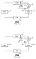
- Fig. 1 shows a typical vapor expansion system, such as an organic rankine cycle (ORC) system, in accordance with the prior art.
- An evaporator provides hot, high pressure vapor to a turbine 13, which converts the energy to kinetic energy, with the lower pressure, lower temperature vapor then passing to a condenser 14, with the resultant liquid then being pumped by a pump 16 back to the evaporator 12.
- ORC organic rankine cycle
- the turbine 13 is bearing mounted, and the bearings require a lubricant which is provided to the turbine 13 by way of an attached accumulator or sump 17.
- a lubricant which is provided to the turbine 13 by way of an attached accumulator or sump 17.
- an oil separator 18 is provided to separate the oil from the vapor, with the vapor then passing on to the condenser 14 and the separated oil being passed to the sump 17 by way of a pump 19.
- One form of pump that may be used is an eductor which operates on the basis of high pressure refrigerant from the evaporator.
- a vent line 21 is normally provided from an upper portion of the sump 17 to the oil separator 18 such that any vapor in the sump 17, which is at a higher pressure than the oil separator 18, will pass along the vent line 21 and return to the working fluid main path.
- a vapor compression system which is shown generally in Fig. 2 , is similar to the vapor expansion system as set forth above and includes an evaporator 22, a compressor 23, a condenser 24 and an expansion device 26.
- the evaporator 22 passes low pressure vapor to a compressor 23, with the resultant high pressure vapor then passing to the condenser 24.
- Liquid refrigerant is then passed to the expansion device 26 for an expansion of the liquid/vapor mixture to the evaporator 22.
- the vapor compression system has a sump 27 for the lubrication of the bearings in the compressor 23, an oil separator 28, a pump 29 and a vent line 31.
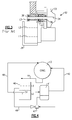
- the rotating machinery which may be either the turbine or the compressor, is shown generally at 32 has including a rotor 33 mounted on the shaft 34 which, in turn, is rotatably supported by way of bearings 36, 37 and 38.
- a sump 39 is mounted below the bearings for the purpose of lubricating those bearings.
- L 1 In order that sufficient oil is available for delivery to the bearings, a minimum oil level, L 1 is established. Thus, during operation, the oil level should be at least at that level. An ideal or preferred level is shown at L 2 . Finally, a third level, or a high level, is shown at L 3 wherein the oil is above the lowest portion of the bearing 38 such that an excess of oil is provided to the bearings so as thereby possibly provide a skid and then eventually result in bearing failure. It is therefore desirable to determine when the oil level exceeds the ideal level L 2 and to prevent its reaching the high level of L 3 .
- FIG. 4 there is shown an oil separator 41 which receives flow from either the turbine or the compressor as described hereinabove and passes vapor along line 42 to the condenser 43, with the condensate then passing along line 44 to either the pump, in the case of the expansion system or the expansion device, in the case of the vapor compression system.
- the sump 46 is attached to either the turbine 13 or the compressor 23 in the manner described hereinabove.
- an eductor 47 causes lubricant to be pumped from the oil separator 41 to the sump 46 along line 48.
- an oil/vapor vent line 49 is connected from a strategic location within the sump 46 to the condenser 43. That is, the oil/vapor vent line has its one end 51 placed within the accumulator 46 at a level which is at the level L2 and below the level L 3 at which problems would arise as discussed hereinabove.
- the higher pressure in the accumulator 46 causes the oil to flow from the sump 46 to the condenser 43.
- the oil level is controlled to maximum of level L2 and prevented from substantially exceeding the level L 2 , such that it will never reach the level L 3 to cause the problems as discussed hereinabove.
- refrigerant vapor will be caused by the higher pressure in the sump 46 to flow to the condenser 43 in the same manner as described hereinabove with respect to the prior art.
- a level sensor 52 is installed to sense the level of lubricant in the sump 46 and to responsively activate by line 54 the pump 19 and/or a control valve (55) in order to pump the excess lubricant to the condenser 43.
- a control valve configuration where an existing pump 19 used to lubricate the bearings has excess capacity, oil can be evacuated from the oil sump 46 using existing hardware and only the addition of a control valve 55 to redirect a small portion of the oil flow.
- the pump is unique for this purpose the pump 19 would only be active during periods in which the level sensor 52 indicates that the level of the lubricant in the accumulator 46 is above a desired level.
- FIG. 6 Another embodiment is shown in Fig. 6 wherein, rather then a pump, an eductor 56 is connected to a dip tube 57 strategically located within the accumulator 46 in order to pump out any excess oil when it reaches the level of the dip tube 57.
- high pressure refrigerant is being supplied to the eductor 56 such that it is operating at all times, even when the lubricant level is below the level of the tip tube 57, such that only vapor would be pumped to the condenser 43.
- the use of a more expensive control valve and its associated power consumption as shown in Fig. 5 is avoided and a passive mechanical system provides protection whenever the equipment is operating.
Landscapes
- Engineering & Computer Science (AREA)
- Mechanical Engineering (AREA)
- General Engineering & Computer Science (AREA)
- Physics & Mathematics (AREA)
- Thermal Sciences (AREA)
- Structures Of Non-Positive Displacement Pumps (AREA)
- Engine Equipment That Uses Special Cycles (AREA)
Claims (9)
- Procédé pour empêcher le niveau de lubrifiant dans un carter de turbine/compresseur (46) d'un système d'expansion/compression de vapeur d'atteindre un niveau suffisamment élevé (L3) pour provoquer une panne mécanique dans l'équipement rotatif de la turbine et du compresseur incluant des paliers (36, 37, 38), comprenant les étapes de :fourniture d'une voie pompée (49 ; 54 ; 57) hors du carter (46) de sorte que le lubrifiant puisse être retiré du carter d'huile (46) à un niveau seuil prédéterminé (L2) ;fourniture d'une réponse passive ou active qui provoque le retrait d'huile par cette voie (49 ; 54 ; 57) lorsque le niveau de lubrifiant atteint le niveau prédéterminé (L2) dans le carter (46)détermination du moment où le niveau de lubrifiant dans le carter (46) atteint un niveau seuil prédéterminé (L2) qui est supérieur à un niveau requis minimum (L1) et inférieur au niveau élevé (L3) ; etprovocation en réponse du pompage du lubrifiant hors du carter (46) de sorte que le niveau de lubrifiant n'excède pas sensiblement ledit niveau seuil prédéterminé (L2) ;caractérisé en ce que ledit lubrifiant est pompé hors du carter (46) et dans un condensateur (43).
- Procédé selon la revendication 1, dans lequel ledit système d'expansion/compression de vapeur comporte un tube d'aération d'huile (49) s'étendant dudit carter (46) audit condensateur (43), ledit tube d'aération d'huile (49) s'étendant dans ledit carter (46) avec une extrémité ouverte (51) agencée audit niveau acceptable (L2) et la pression dans ledit carter (46) étant plus grande que dans ledit condensateur (43) de sorte que lorsque le niveau d'huile dans le carter (46) est au-dessus de l'extrémité ouverte d'aération d'huile (51), elle sera amenée à s'écouler par le tube d'aération d'huile (49) jusqu'au condensateur (43).
- Procédé selon la revendication 1, dans lequel ledit système d'expansion/compression de vapeur comporte une pompe (53) et un capteur de niveau (52), ladite pompe (53) étant en communication fluidique entre ledit carter (46) et ledit condensateur (43), et ledit capteur de niveau (52) étant fonctionnel pour détecter le niveau de lubrifiant dans ledit carter et en outre dans lequel ledit capteur de niveau (52) amène en réponse ladite pompe (53) à provoquer le pompage de l'huile hors du carter (46).
- Procédé selon la revendication 1, dans lequel ledit système d'expansion/compression de vapeur comporte un éjecteur (56) et un tube plongeur (57), ledit éjecteur (56) étant relié fluidiquement entre ledit carter d'huile (46) et ledit condensateur (43), et ledit tube plongeur (57) étant agencé dans ledit carter d'huile (46) audit niveau acceptable (L2) de sorte que lorsque le niveau d'huile est au-dessus dudit tube plongeur (57), ledit éjecteur (56) amène l'huile à être pompée hors du carter (46).
- Procédé selon la revendication 1, dans lequel ladite ligne d'aération d'huile/vapeur a une extrémité ouverte (51) agencée audit niveau prédéterminé (L2) dans ledit carter (46) et en outre dans lequel la pression dans le carter (46) est supérieure à la pression dans le condensateur (43) de sorte à provoquer le flux d'huile et/ou de fluide de travail du carter (46) au condensateur (43).
- Système de compression ou d'expansion de vapeur à boucle fermée présentant un séparateur d'huile (41), un condensateur (43) et un compresseur (23) ou une turbine (13) avec des paliers (36, 37, 38) à lubrifier à partir d'un carter d'huile (46) situé sous les paliers (36, 37, 38), comprenant :une pompe (47) pour amener de l'huile à s'écouler du séparateur d'huile (41) au carter d'huile (46) ;caractérisé en ce qu'il comprend en outre :une ligne d'aération d'huile/vapeur (49 ; 54 ; 57) communiquant fluidiquement entre le carter (46) et le condensateur (43) ; etun moyen provoquant le flux de fluide (51 ; 53 ; 56) pour amener l'huile à s'écouler du carter (46) au condensateur (43) à l'aide de ladite ligne d'aération d'huile/vapeur (49 ; 54 ; 57) lorsqu'un niveau d'huile dans le carter (46) est supérieur à un niveau prédéterminé (L2).
- Système de compression et d'expansion de vapeur à boucle fermée selon la revendication 6, dans lequel ladite ligne d'aération d'huile/vapeur (49) a une extrémité ouverte (51) agencée sur ledit niveau prédéterminé (L2) dans le carter (46) et en outre dans lequel la pression dans le carter (46) est supérieure à la pression dans le condensateur (43) de sorte à provoquer le flux d'huile du carter (46) au condensateur (43).
- Système de compression ou d'expansion de vapeur à boucle fermée selon la revendication 6 et incluant un capteur (52) pour déterminer le niveau d'huile dans le carter (46) et une pompe (53) pour pomper en réponse de l'huile du carter (46) au condensateur (43) lorsque le niveau d'huile est supérieur audit niveau prédéterminé (L2).
- Système de compression ou d'expansion de vapeur à boucle fermée selon la revendication 6, dans lequel ledit moyen provoquant le flux de fluide comprend un éjecteur (56).
Applications Claiming Priority (1)
| Application Number | Priority Date | Filing Date | Title |
|---|---|---|---|
| PCT/US2008/062878 WO2009136919A1 (fr) | 2008-05-07 | 2008-05-07 | Limiteur passif de niveau d’huile |
Publications (3)
| Publication Number | Publication Date |
|---|---|
| EP2288794A1 EP2288794A1 (fr) | 2011-03-02 |
| EP2288794A4 EP2288794A4 (fr) | 2014-08-27 |
| EP2288794B1 true EP2288794B1 (fr) | 2016-11-23 |
Family
ID=41264824
Family Applications (1)
| Application Number | Title | Priority Date | Filing Date |
|---|---|---|---|
| EP08747774.1A Active EP2288794B1 (fr) | 2008-05-07 | 2008-05-07 | Limiteur passif de niveau d huile |
Country Status (3)
| Country | Link |
|---|---|
| US (1) | US9541312B2 (fr) |
| EP (1) | EP2288794B1 (fr) |
| WO (1) | WO2009136919A1 (fr) |
Families Citing this family (6)
| Publication number | Priority date | Publication date | Assignee | Title |
|---|---|---|---|---|
| US10184700B2 (en) * | 2009-02-09 | 2019-01-22 | Total Green Mfg. Corp. | Oil return system and method for active charge control in an air conditioning system |
| JP6163145B2 (ja) * | 2014-09-05 | 2017-07-12 | 株式会社神戸製鋼所 | 熱エネルギー回収装置 |
| CN110914545B (zh) * | 2017-07-28 | 2022-11-01 | 开利公司 | 润滑供应系统 |
| EP3814695A1 (fr) | 2018-06-26 | 2021-05-05 | Carrier Corporation | Procédé amélioré de lubrification pour compresseurs de réfrigération |
| US11162637B2 (en) | 2019-09-30 | 2021-11-02 | Hamilton Sundstrand Corporation | Sump cover assembly for generator |
| CN115493306A (zh) | 2021-06-17 | 2022-12-20 | 开利公司 | 制冷系统和用于其的回油方法 |
Family Cites Families (27)
| Publication number | Priority date | Publication date | Assignee | Title |
|---|---|---|---|---|
| US2792912A (en) | 1954-12-17 | 1957-05-21 | Reino W Kangas | Automatic control system for lubricant supply |
| US3632235A (en) * | 1969-06-09 | 1972-01-04 | Carl A Grenci | Cryogenic pump system |
| DE3041914A1 (de) * | 1980-11-06 | 1982-06-16 | Vdo Adolf Schindling Ag, 6000 Frankfurt | Einrichtung zur kapazitiven fuellstandsmessung |
| US4503685A (en) * | 1982-11-19 | 1985-03-12 | Hussmann Corporation | Oil control valve for refrigeration system |
| US4478050A (en) * | 1982-11-19 | 1984-10-23 | Hussmann Corporation | Oil separation for refrigeration system |
| US4530215A (en) * | 1983-08-16 | 1985-07-23 | Kramer Daniel E | Refrigeration compressor with pump actuated oil return |
| US4748820A (en) * | 1984-01-11 | 1988-06-07 | Copeland Corporation | Refrigeration system |
| US4573327A (en) | 1984-09-21 | 1986-03-04 | Robert Cochran | Fluid flow control system |
| US4551989A (en) * | 1984-11-30 | 1985-11-12 | Gulf & Western Manufacturing Company | Oil equalization system for refrigeration compressors |
| JP3128293B2 (ja) * | 1991-11-06 | 2001-01-29 | 三洋電機株式会社 | 冷凍装置の油面制御装置 |
| JPH05280322A (ja) * | 1992-03-30 | 1993-10-26 | Shinko Electric Co Ltd | エンジンにおける潤滑油面の管理システム |
| US5327997A (en) | 1993-01-22 | 1994-07-12 | Temprite, Inc. | Lubrication management system |
| US5321956A (en) * | 1993-05-26 | 1994-06-21 | Kemp Industrial Refrigeration, Inc. | Oil management and removal system for a refrigeration installation |
| AUPM630094A0 (en) * | 1994-06-17 | 1994-07-14 | Refrigerant Monitoring Systems Pty Ltd | Oil level control device |
| US5586450A (en) * | 1995-09-25 | 1996-12-24 | Carrier Corporation | Plural compressor oil level control |
| US5901559A (en) * | 1998-09-09 | 1999-05-11 | Ac&R Components, Inc. | Electromechanical regulator |
| US6481973B1 (en) | 1999-10-27 | 2002-11-19 | Little Giant Pump Company | Method of operating variable-speed submersible pump unit |
| US6687122B2 (en) * | 2001-08-30 | 2004-02-03 | Sun Microsystems, Inc. | Multiple compressor refrigeration heat sink module for cooling electronic components |
| JP4378176B2 (ja) * | 2002-04-08 | 2009-12-02 | ダイキン工業株式会社 | 冷凍装置 |
| JP4300804B2 (ja) * | 2002-06-11 | 2009-07-22 | ダイキン工業株式会社 | 圧縮機構の均油回路、冷凍装置の熱源ユニット及びそれを備えた冷凍装置 |
| US7174716B2 (en) | 2002-11-13 | 2007-02-13 | Utc Power Llc | Organic rankine cycle waste heat applications |
| US20040144093A1 (en) * | 2003-01-28 | 2004-07-29 | Hanna William Thompson | Lubrication management of a pump for a micro combined heat and power system |
| US7082774B2 (en) * | 2003-08-27 | 2006-08-01 | Zahid Hussain Ayub | Compressor oil removal in ammonia refrigeration system |
| JP4027295B2 (ja) * | 2003-10-02 | 2007-12-26 | 本田技研工業株式会社 | ランキンサイクル装置における凝縮器の液面位置制御装置 |
| JP3939314B2 (ja) * | 2004-06-10 | 2007-07-04 | 三星電子株式会社 | 空気調和装置及びその均油運転方法 |
| US7231783B2 (en) * | 2004-08-27 | 2007-06-19 | Zero Zone, Inc. | Oil control system for a refrigeration system |
| AU2007357134B2 (en) * | 2007-07-27 | 2014-04-17 | United Technologies Corporation | Oil recovery from an evaporator of an organic rankine cycle (ORC) system |
-
2008
- 2008-05-07 WO PCT/US2008/062878 patent/WO2009136919A1/fr not_active Ceased
- 2008-05-07 EP EP08747774.1A patent/EP2288794B1/fr active Active
- 2008-05-07 US US12/991,288 patent/US9541312B2/en active Active
Also Published As
| Publication number | Publication date |
|---|---|
| EP2288794A1 (fr) | 2011-03-02 |
| US9541312B2 (en) | 2017-01-10 |
| WO2009136919A1 (fr) | 2009-11-12 |
| US20110120154A1 (en) | 2011-05-26 |
| EP2288794A4 (fr) | 2014-08-27 |
Similar Documents
| Publication | Publication Date | Title |
|---|---|---|
| EP2288794B1 (fr) | Limiteur passif de niveau d huile | |
| EP2297461B1 (fr) | Systeme de lubrification pour un systeme d'engrenages pour eolienne | |
| EP2491245B1 (fr) | Système de lubrification destiné à un système d'engrenage et assurant une lubrification d'urgence | |
| CA2583436C (fr) | Systeme et methode d'equilibrage de l'huile des compresseurs raccordes en serie | |
| US10655726B2 (en) | Lubrication system with passive valve | |
| EP2959238B1 (fr) | Système de pompe à chaleur | |
| EP1496302B1 (fr) | Dispositif de lubrification passif et capable de compenser une défaillance | |
| EP3187768B1 (fr) | Système et procédé de détermination dynamique de l'épaisseur d'un film de réfrigérant et de régulation dynamique de l'épaisseur d'un film de réfrigérant au niveau du roulement d'élément roulant d'un refroidisseur sans huile | |
| EP2778478B1 (fr) | Système de lubrification avec soupape de drainage passif | |
| EP1729055B1 (fr) | Méthode pour lubrifier un palier à roulement avec un fluide volatile et à très basse viscosité | |
| KR102769288B1 (ko) | 예비 탱크를 갖는 윤활 시스템 | |
| EP3745049B1 (fr) | Appareil de réfrigération | |
| US11834972B2 (en) | Turbomachinery lubrication system improvement gravity rundown tanks | |
| EP3904683B1 (fr) | Système d'alimentation en lubrification | |
| JP4448390B2 (ja) | 冷凍装置 | |
| EP2990739B1 (fr) | Procédé pour la lubrification externe forcée de compresseurs de réfrigération | |
| EP2281118B1 (fr) | Compresseur | |
| US3250082A (en) | Refrigeration system lubrication | |
| EP2309125A2 (fr) | Système de réfrigération auxiliaire et méthode d'exploitation |
Legal Events
| Date | Code | Title | Description |
|---|---|---|---|
| PUAI | Public reference made under article 153(3) epc to a published international application that has entered the european phase |
Free format text: ORIGINAL CODE: 0009012 |
|
| 17P | Request for examination filed |
Effective date: 20101207 |
|
| AK | Designated contracting states |
Kind code of ref document: A1 Designated state(s): AT BE BG CH CY CZ DE DK EE ES FI FR GB GR HR HU IE IS IT LI LT LU LV MC MT NL NO PL PT RO SE SI SK TR |
|
| AX | Request for extension of the european patent |
Extension state: AL BA MK RS |
|
| DAX | Request for extension of the european patent (deleted) | ||
| A4 | Supplementary search report drawn up and despatched |
Effective date: 20140729 |
|
| RIC1 | Information provided on ipc code assigned before grant |
Ipc: F01D 25/20 20060101ALI20140723BHEP Ipc: F01K 1/00 20060101ALI20140723BHEP Ipc: F01K 7/00 20060101ALI20140723BHEP Ipc: F25B 31/00 20060101ALI20140723BHEP Ipc: F01K 23/06 20060101AFI20140723BHEP |
|
| GRAP | Despatch of communication of intention to grant a patent |
Free format text: ORIGINAL CODE: EPIDOSNIGR1 |
|
| INTG | Intention to grant announced |
Effective date: 20160607 |
|
| GRAS | Grant fee paid |
Free format text: ORIGINAL CODE: EPIDOSNIGR3 |
|
| GRAA | (expected) grant |
Free format text: ORIGINAL CODE: 0009210 |
|
| RAP1 | Party data changed (applicant data changed or rights of an application transferred) |
Owner name: UNITED TECHNOLOGIES CORPORATION |
|
| AK | Designated contracting states |
Kind code of ref document: B1 Designated state(s): AT BE BG CH CY CZ DE DK EE ES FI FR GB GR HR HU IE IS IT LI LT LU LV MC MT NL NO PL PT RO SE SI SK TR |
|
| REG | Reference to a national code |
Ref country code: GB Ref legal event code: FG4D |
|
| REG | Reference to a national code |
Ref country code: CH Ref legal event code: EP |
|
| REG | Reference to a national code |
Ref country code: IE Ref legal event code: FG4D |
|
| REG | Reference to a national code |
Ref country code: AT Ref legal event code: REF Ref document number: 848115 Country of ref document: AT Kind code of ref document: T Effective date: 20161215 |
|
| REG | Reference to a national code |
Ref country code: DE Ref legal event code: R096 Ref document number: 602008047519 Country of ref document: DE |
|
| PG25 | Lapsed in a contracting state [announced via postgrant information from national office to epo] |
Ref country code: LV Free format text: LAPSE BECAUSE OF FAILURE TO SUBMIT A TRANSLATION OF THE DESCRIPTION OR TO PAY THE FEE WITHIN THE PRESCRIBED TIME-LIMIT Effective date: 20161123 |
|
| REG | Reference to a national code |
Ref country code: LT Ref legal event code: MG4D |
|
| REG | Reference to a national code |
Ref country code: NL Ref legal event code: MP Effective date: 20161123 |
|
| REG | Reference to a national code |
Ref country code: AT Ref legal event code: MK05 Ref document number: 848115 Country of ref document: AT Kind code of ref document: T Effective date: 20161123 |
|
| PG25 | Lapsed in a contracting state [announced via postgrant information from national office to epo] |
Ref country code: SE Free format text: LAPSE BECAUSE OF FAILURE TO SUBMIT A TRANSLATION OF THE DESCRIPTION OR TO PAY THE FEE WITHIN THE PRESCRIBED TIME-LIMIT Effective date: 20161123 Ref country code: NO Free format text: LAPSE BECAUSE OF FAILURE TO SUBMIT A TRANSLATION OF THE DESCRIPTION OR TO PAY THE FEE WITHIN THE PRESCRIBED TIME-LIMIT Effective date: 20170223 Ref country code: LT Free format text: LAPSE BECAUSE OF FAILURE TO SUBMIT A TRANSLATION OF THE DESCRIPTION OR TO PAY THE FEE WITHIN THE PRESCRIBED TIME-LIMIT Effective date: 20161123 Ref country code: NL Free format text: LAPSE BECAUSE OF FAILURE TO SUBMIT A TRANSLATION OF THE DESCRIPTION OR TO PAY THE FEE WITHIN THE PRESCRIBED TIME-LIMIT Effective date: 20161123 Ref country code: GR Free format text: LAPSE BECAUSE OF FAILURE TO SUBMIT A TRANSLATION OF THE DESCRIPTION OR TO PAY THE FEE WITHIN THE PRESCRIBED TIME-LIMIT Effective date: 20170224 |
|
| PG25 | Lapsed in a contracting state [announced via postgrant information from national office to epo] |
Ref country code: PL Free format text: LAPSE BECAUSE OF FAILURE TO SUBMIT A TRANSLATION OF THE DESCRIPTION OR TO PAY THE FEE WITHIN THE PRESCRIBED TIME-LIMIT Effective date: 20161123 Ref country code: HR Free format text: LAPSE BECAUSE OF FAILURE TO SUBMIT A TRANSLATION OF THE DESCRIPTION OR TO PAY THE FEE WITHIN THE PRESCRIBED TIME-LIMIT Effective date: 20161123 Ref country code: FI Free format text: LAPSE BECAUSE OF FAILURE TO SUBMIT A TRANSLATION OF THE DESCRIPTION OR TO PAY THE FEE WITHIN THE PRESCRIBED TIME-LIMIT Effective date: 20161123 Ref country code: ES Free format text: LAPSE BECAUSE OF FAILURE TO SUBMIT A TRANSLATION OF THE DESCRIPTION OR TO PAY THE FEE WITHIN THE PRESCRIBED TIME-LIMIT Effective date: 20161123 Ref country code: AT Free format text: LAPSE BECAUSE OF FAILURE TO SUBMIT A TRANSLATION OF THE DESCRIPTION OR TO PAY THE FEE WITHIN THE PRESCRIBED TIME-LIMIT Effective date: 20161123 Ref country code: PT Free format text: LAPSE BECAUSE OF FAILURE TO SUBMIT A TRANSLATION OF THE DESCRIPTION OR TO PAY THE FEE WITHIN THE PRESCRIBED TIME-LIMIT Effective date: 20170323 |
|
| REG | Reference to a national code |
Ref country code: DE Ref legal event code: R082 Ref document number: 602008047519 Country of ref document: DE Representative=s name: SCHMITT-NILSON SCHRAUD WAIBEL WOHLFROM PATENTA, DE |
|
| PG25 | Lapsed in a contracting state [announced via postgrant information from national office to epo] |
Ref country code: RO Free format text: LAPSE BECAUSE OF FAILURE TO SUBMIT A TRANSLATION OF THE DESCRIPTION OR TO PAY THE FEE WITHIN THE PRESCRIBED TIME-LIMIT Effective date: 20161123 Ref country code: SK Free format text: LAPSE BECAUSE OF FAILURE TO SUBMIT A TRANSLATION OF THE DESCRIPTION OR TO PAY THE FEE WITHIN THE PRESCRIBED TIME-LIMIT Effective date: 20161123 Ref country code: CZ Free format text: LAPSE BECAUSE OF FAILURE TO SUBMIT A TRANSLATION OF THE DESCRIPTION OR TO PAY THE FEE WITHIN THE PRESCRIBED TIME-LIMIT Effective date: 20161123 Ref country code: EE Free format text: LAPSE BECAUSE OF FAILURE TO SUBMIT A TRANSLATION OF THE DESCRIPTION OR TO PAY THE FEE WITHIN THE PRESCRIBED TIME-LIMIT Effective date: 20161123 Ref country code: DK Free format text: LAPSE BECAUSE OF FAILURE TO SUBMIT A TRANSLATION OF THE DESCRIPTION OR TO PAY THE FEE WITHIN THE PRESCRIBED TIME-LIMIT Effective date: 20161123 |
|
| REG | Reference to a national code |
Ref country code: DE Ref legal event code: R097 Ref document number: 602008047519 Country of ref document: DE |
|
| PG25 | Lapsed in a contracting state [announced via postgrant information from national office to epo] |
Ref country code: LU Free format text: LAPSE BECAUSE OF NON-PAYMENT OF DUE FEES Effective date: 20170531 Ref country code: BG Free format text: LAPSE BECAUSE OF FAILURE TO SUBMIT A TRANSLATION OF THE DESCRIPTION OR TO PAY THE FEE WITHIN THE PRESCRIBED TIME-LIMIT Effective date: 20170223 Ref country code: BE Free format text: LAPSE BECAUSE OF FAILURE TO SUBMIT A TRANSLATION OF THE DESCRIPTION OR TO PAY THE FEE WITHIN THE PRESCRIBED TIME-LIMIT Effective date: 20161123 Ref country code: IT Free format text: LAPSE BECAUSE OF FAILURE TO SUBMIT A TRANSLATION OF THE DESCRIPTION OR TO PAY THE FEE WITHIN THE PRESCRIBED TIME-LIMIT Effective date: 20161123 |
|
| PLBE | No opposition filed within time limit |
Free format text: ORIGINAL CODE: 0009261 |
|
| STAA | Information on the status of an ep patent application or granted ep patent |
Free format text: STATUS: NO OPPOSITION FILED WITHIN TIME LIMIT |
|
| 26N | No opposition filed |
Effective date: 20170824 |
|
| PG25 | Lapsed in a contracting state [announced via postgrant information from national office to epo] |
Ref country code: SI Free format text: LAPSE BECAUSE OF FAILURE TO SUBMIT A TRANSLATION OF THE DESCRIPTION OR TO PAY THE FEE WITHIN THE PRESCRIBED TIME-LIMIT Effective date: 20161123 |
|
| REG | Reference to a national code |
Ref country code: CH Ref legal event code: PL |
|
| PG25 | Lapsed in a contracting state [announced via postgrant information from national office to epo] |
Ref country code: MC Free format text: LAPSE BECAUSE OF FAILURE TO SUBMIT A TRANSLATION OF THE DESCRIPTION OR TO PAY THE FEE WITHIN THE PRESCRIBED TIME-LIMIT Effective date: 20161123 |
|
| REG | Reference to a national code |
Ref country code: IE Ref legal event code: MM4A |
|
| PG25 | Lapsed in a contracting state [announced via postgrant information from national office to epo] |
Ref country code: LI Free format text: LAPSE BECAUSE OF NON-PAYMENT OF DUE FEES Effective date: 20170531 Ref country code: CH Free format text: LAPSE BECAUSE OF NON-PAYMENT OF DUE FEES Effective date: 20170531 |
|
| REG | Reference to a national code |
Ref country code: FR Ref legal event code: ST Effective date: 20180131 |
|
| PG25 | Lapsed in a contracting state [announced via postgrant information from national office to epo] |
Ref country code: LU Free format text: LAPSE BECAUSE OF NON-PAYMENT OF DUE FEES Effective date: 20170507 |
|
| PG25 | Lapsed in a contracting state [announced via postgrant information from national office to epo] |
Ref country code: IE Free format text: LAPSE BECAUSE OF NON-PAYMENT OF DUE FEES Effective date: 20170507 |
|
| PG25 | Lapsed in a contracting state [announced via postgrant information from national office to epo] |
Ref country code: FR Free format text: LAPSE BECAUSE OF NON-PAYMENT OF DUE FEES Effective date: 20170531 |
|
| PG25 | Lapsed in a contracting state [announced via postgrant information from national office to epo] |
Ref country code: MT Free format text: LAPSE BECAUSE OF NON-PAYMENT OF DUE FEES Effective date: 20170507 |
|
| PG25 | Lapsed in a contracting state [announced via postgrant information from national office to epo] |
Ref country code: HU Free format text: LAPSE BECAUSE OF FAILURE TO SUBMIT A TRANSLATION OF THE DESCRIPTION OR TO PAY THE FEE WITHIN THE PRESCRIBED TIME-LIMIT; INVALID AB INITIO Effective date: 20080507 |
|
| PG25 | Lapsed in a contracting state [announced via postgrant information from national office to epo] |
Ref country code: CY Free format text: LAPSE BECAUSE OF NON-PAYMENT OF DUE FEES Effective date: 20161123 |
|
| PG25 | Lapsed in a contracting state [announced via postgrant information from national office to epo] |
Ref country code: TR Free format text: LAPSE BECAUSE OF FAILURE TO SUBMIT A TRANSLATION OF THE DESCRIPTION OR TO PAY THE FEE WITHIN THE PRESCRIBED TIME-LIMIT Effective date: 20161123 |
|
| PG25 | Lapsed in a contracting state [announced via postgrant information from national office to epo] |
Ref country code: IS Free format text: LAPSE BECAUSE OF FAILURE TO SUBMIT A TRANSLATION OF THE DESCRIPTION OR TO PAY THE FEE WITHIN THE PRESCRIBED TIME-LIMIT Effective date: 20170323 |
|
| REG | Reference to a national code |
Ref country code: DE Ref legal event code: R081 Ref document number: 602008047519 Country of ref document: DE Owner name: RAYTHEON TECHNOLOGIES CORPORATION (N.D.GES.D.S, US Free format text: FORMER OWNER: UNITED TECHNOLOGIES CORPORATION, FARMINGTON, CONN., US Ref country code: DE Ref legal event code: R081 Ref document number: 602008047519 Country of ref document: DE Owner name: RTX CORPORATION (N.D.GES.D. STAATES DELAWARE),, US Free format text: FORMER OWNER: UNITED TECHNOLOGIES CORPORATION, FARMINGTON, CONN., US |
|
| P01 | Opt-out of the competence of the unified patent court (upc) registered |
Effective date: 20230521 |
|
| PGFP | Annual fee paid to national office [announced via postgrant information from national office to epo] |
Ref country code: DE Payment date: 20250423 Year of fee payment: 18 |
|
| PGFP | Annual fee paid to national office [announced via postgrant information from national office to epo] |
Ref country code: GB Payment date: 20250423 Year of fee payment: 18 |
|
| REG | Reference to a national code |
Ref country code: DE Ref legal event code: R081 Ref document number: 602008047519 Country of ref document: DE Owner name: RTX CORPORATION (N.D.GES.D. STAATES DELAWARE),, US Free format text: FORMER OWNER: RAYTHEON TECHNOLOGIES CORPORATION (N.D.GES.D.STAATES DELAWARE), ARLINGTON, VA, US |