EP2288932B1 - Procédé et appareil pour estimer la distance plus probable entre objets - Google Patents
Procédé et appareil pour estimer la distance plus probable entre objets Download PDFInfo
- Publication number
- EP2288932B1 EP2288932B1 EP09738122.2A EP09738122A EP2288932B1 EP 2288932 B1 EP2288932 B1 EP 2288932B1 EP 09738122 A EP09738122 A EP 09738122A EP 2288932 B1 EP2288932 B1 EP 2288932B1
- Authority
- EP
- European Patent Office
- Prior art keywords
- objects
- pattern
- distance
- acoustic signal
- sound
- Prior art date
- Legal status (The legal status is an assumption and is not a legal conclusion. Google has not performed a legal analysis and makes no representation as to the accuracy of the status listed.)
- Active
Links
Images





Classifications
-
- G—PHYSICS
- G01—MEASURING; TESTING
- G01S—RADIO DIRECTION-FINDING; RADIO NAVIGATION; DETERMINING DISTANCE OR VELOCITY BY USE OF RADIO WAVES; LOCATING OR PRESENCE-DETECTING BY USE OF THE REFLECTION OR RERADIATION OF RADIO WAVES; ANALOGOUS ARRANGEMENTS USING OTHER WAVES
- G01S11/00—Systems for determining distance or velocity not using reflection or reradiation
- G01S11/14—Systems for determining distance or velocity not using reflection or reradiation using ultrasonic, sonic or infrasonic waves
-
- G—PHYSICS
- G01—MEASURING; TESTING
- G01S—RADIO DIRECTION-FINDING; RADIO NAVIGATION; DETERMINING DISTANCE OR VELOCITY BY USE OF RADIO WAVES; LOCATING OR PRESENCE-DETECTING BY USE OF THE REFLECTION OR RERADIATION OF RADIO WAVES; ANALOGOUS ARRANGEMENTS USING OTHER WAVES
- G01S5/00—Position-fixing by co-ordinating two or more direction or position line determinations; Position-fixing by co-ordinating two or more distance determinations
- G01S5/02—Position-fixing by co-ordinating two or more direction or position line determinations; Position-fixing by co-ordinating two or more distance determinations using radio waves
- G01S5/0284—Relative positioning
- G01S5/0289—Relative positioning of multiple transceivers, e.g. in ad hoc networks
Definitions
- the invention relates to a method according to claim 1 and a device having the features of claim 7.
- a localization can be understood here to mean that the spatial relationship of the objects with one another and / or the spatial relationship of the objects relative to a reference system, such as a fixed space, is determined.
- this also includes hybridization of the location in which the location of a first mobile device relative to a fixed frame of reference is determined, namely the determination of the distance of the objects, e.g. two mobile devices with each other
- the US 2004/137929 A1 describes a communication system in which data is transmitted and / or received acoustically. Positioning of devices is possible due to transmitted signals.
- the WO 2007/001660 A2 relates to a localization of a mobile device by means of Wi-Fi, FM, AM or other signals.
- the present invention has for its object to provide a method by which this flexible location, in particular a self-localization is possible.
- the time profile of the respective received acoustic signal is automatically searched on the basis of predetermined criteria according to at least one pattern and depending on the reception of the at least one pattern by means of a time synchronization over which the objects are coupled, a determination of the most probable distance estimation between the objects ,
- the at least one pattern is an onset of the at least one acoustic signal or the acoustic signal has an onset and the onset is a sound, a noise, a sound pattern and / or a noise pattern originating from the surroundings of the objects, namely a ambient noise and / or ambient sound.
- a value for the distance estimation (distance min ) between the mobile objects which represents a distance between the two microphone devices as a minimum distance estimation, is determined with the aid of the measured transit time difference between two determined and probably the same rated patterns in the acoustic signal
- a statistical analysis is performed on a series of minimum distance estimates for determining the most probable distance estimation of the objects, wherein the statistical analysis comprises an evaluation of a class of distance measurements, and wherein the maximum frequency of the aggregated at least one minimum distance estimate is the characteristic distance Class forms.
- the data processing device may be a distributed system that is located entirely outside of the objects, it may be located partly in the objects, partly separately, or it may be completely disposed in the objects so that the objects exchange data with each other.
- a statistical analysis of the incoming at least one object at least one acoustic signal for determining the most probable position of the object and / or the most probable position of at least two objects is performed. This makes it possible to perform position determinations even with noisy signals.
- the temporal data of the arrival of the at least one pattern and the resulting different periods of at least two objects automatically determines a distance between the at least two objects.
- This method is generally applicable to more than two items at the same time.
- the at least one pattern is an onset of the at least one acoustic signal, namely a sudden change in volume and / or a change in sound pressure after a preceding phase of relative rest and / or a signal generated on the basis of the Doppler effect.
- These patterns have in common that they are extractable from a more complex acoustic signal.
- the search for the at least one pattern is based on a property of the at least one acoustic signal which is independent of the propagation path of the acoustic signal.
- these properties are e.g. the zero crossings of a time-varying signal. Basically, the frequency and waveform of an acoustic signal are relatively independent of the propagation path.
- the search for a pattern it should be found that there is a signal pattern that is likely to be usable for the location of the objects. In order to determine the transit time differences, these signal patterns must be grouped according to their origin. The zero crossings and / or other properties are used to group the found onsets.
- the distance between the two microphones is at least as large as the propagation speed mulitipli extend with the transit time difference.
- the at least one pattern is determined by a frequency analysis, by means of a dominant frequency, Based on the amplitude of the at least one acoustic signal, based on the number of zero crossings, a run-length coding and / or the waveform of the at least one acoustic signal is detected and / or characterized.
- a run-length coding and / or the waveform of the at least one acoustic signal is detected and / or characterized.
- a localization between mobile devices 10, 11 takes place.
- the invention can also be used for the localization of stationary objects 10, 11, so that the illustration of the following examples can not be understood as limiting.
- a localization can be carried out in particular a self-localization of the objects, or even the mobile devices.
- Fig. 1 schematically two mobile devices 10, 11 are shown, which are formed in the present embodiment as mobile phones.
- the mobile devices 10, 11 represent autonomous systems that can be carried by a user, for example, or that can move autonomously, such as robots in a workshop.
- the space in which the two mobile devices 10, 11 are located has been reduced to two dimensions here for the sake of simplicity, so that the location of each of the mobile devices 10, 11 can be described by coordinates (x i , y i ).
- the distance of the mobile devices 10, 11 is referred to in the present case as A.
- the mobile devices 10, 11 can also move in a three-dimensional space, so that the locations of the devices are described by coordinates (x i , y i , z i ).
- the mobile devices 10, 11 have microphone devices 1, with which acoustic signals 2 from the environment are recorded.
- an acoustic source 3 is shown, which emits such an acoustic signal 2.
- An acoustic signal is to be understood as meaning a signal in a pressure fluctuation in which a sound wave propagates.
- the medium is air in the following examples, where in principle a localization of objects in a liquid medium (eg water) is possible. If the velocity of propagation is known, localization can also take place across phase boundaries.
- an acoustic signal is understood to mean not only a signal in the audible frequency range (approximately 16 to 20,000 Hz), but the acoustic signal can also have components in the infrared and / or ultrasound range.
- This source 3 does not have to be such that it must be designed for the emission of an acoustic signal. For example, it may be sufficient if two mobile devices 10, 11 register a loud, relatively short-duration noise or a sudden change in an acoustic signal 2 at different times. If two mobile devices 10, 11 are arranged in a room, it may be sufficient, for example, to register the footfall of people walking around. This makes it clear that the at least one source 3 does not have to be stationary.
- the shape of the pattern 5 in these acoustic signals 2 is substantially identical (perhaps differently noisy or registered differently) only by different mobile devices 10, 11 at different times.
- acoustic source 3 is shown, wherein the localization of the mobile devices 10, 11 described below also works with a plurality of acoustic sources 3.
- the acoustic source 3 does not have to be stationary, but it can also move in space.
- the microphone devices 1 of the mobile devices 10, 11 receive the acoustic signal 2. Since the mobile devices 10, 11 are located at different distances from the acoustic source, they register a specific acoustic signal due to the different transit time at different times.
- Fig. 2 is schematically plotted the sound pressure p of an acoustic signal 2 over the time t. Until a time t o the sound pressure is relatively low. After the time t o the sound pressure p is much higher. A person would perceive this change as a sudden change from "quiet" to "loud.”
- the acoustic signal 2 contains a pattern 5, namely the change of the sound pressure p, referred to as onset.
- threshold values for the acoustic signal 2 can be defined whose exceeding or undershooting causes a counter to be used for the onset.
- a pattern 5 can be characterized.
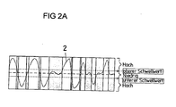
- Fig. 2A is such a classification for acoustic Signals represented by thresholds.
- a sound pressure curve is shown as an acoustic signal 2, which passes through an upper and a lower threshold at irregular intervals. In the areas marked in gray, the sound pressure is between the threshold values.
- the range between the thresholds can be interpreted as "relative silence”. The range outside the thresholds can be interpreted as "relatively loud”.
- the microphone devices 1 register the change of the sound pressure p at different times.
- onset may be a sound, a noise, a sound pattern, and / or a sound pattern originating from the environment of the objects, i. an ambient noise and / or ambient sound. If the pattern 5 evaluates sounds or sounds from the environment, no separate energy is needed to generate a locating signal, resulting in energy savings.
- Run-length coding is intended to describe the beginning portion of a found onset (or other type of sound event or pattern). This description (or characterization as well) should be made independently of the amplitude of the found signal to give the different run length to the individual Microphones of the device and thus to compensate for the different volume of the incoming signal there.
- Fig. 1 an external part of a data processing device 4 is shown, which provides a time synchronization 6 for the mobile devices 10, 11.
- An internal part of the data processing device 7 in the mobile devices 10, 11 automatically searches incoming acoustic signals for patterns 5, which can give information about the relative positions of the mobile devices 10, 11 to the acoustic source 3.
- Which functionalities of the data processing device 4, 7 are formed externally to the mobile devices 10, 11 or internally in the mobile devices 10, 11, depends on the intended use. In principle, it is possible and also advantageous if the entire data processing device is arranged in one or more objects, in particular in the mobile devices 10, 11, which exchange data with one another.
- the distance of the mobile devices 10, 11 from the acoustic source 3 can be calculated.
- the emission time (start time) and / or the arrival time of the signal 2 can be used. If the location of the acoustic source 3 is known, a more accurate localization of the mobile devices 10, 11 can take place.
- the pattern 5 is contained in a sound pressure curve.
- the pattern 5 can also be formed from other parameters of an acoustic signal, such as the frequency, the amplitude or the waveform.
- the pattern 5 may be due to a frequency change resulting from the movement (Doppler effect). Combinations of these features are also possible to form a pattern 5.
- the pattern 5 thus represents a signal that is embedded in the acoustic signal 2, but based on certain predetermined criteria of other parts of the acoustic signal 2 is distinguishable.
- these types of patterns are independent of the propagation path of the acoustic signal 2. Basically, the frequency and the waveform of acoustic signals vary little or no depending on the propagation path.
- One possibility is to determine dominant frequencies by means of a Fourier analysis, in particular an FFT.
- Fig. 4 is an example of the detection of the amplitudes, ie a criterion of the waveform shown.
- an acoustic signal 2 is shown, over which consecutive windows of equal width are laid.
- the height of the windows is equal to the maximum plus the minimum amplitude of the acoustic signal in the windows. With this easily calculated measure, the amplitude of the signal can be easily approximated.
- the heights are shown below the signal in the form of a bar chart.
- the table below shows the values for the amplitude approximation and the measured amplitudes in negative decibels with respect to the maximum possible amplitude.
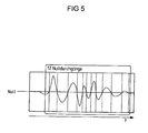
- Fig. 5 is shown how the acoustic signal 2 can be characterized by the evaluation of zero crossings.
- Fig. 6 is a runtime encoding of the signal 2, which is already in Fig. 2A was presented. Due to the runtime coding, the signal 2 is discretized in order to be able to send it memory efficient. The payment below the graph indicate in which periods the signal is outside the threshold values or within the threshold values. The signal 2 is normalized to make it largely independent of differences in amplitude, which may for example come from different microphone characteristics. Normalization may eliminate the need for a volume calibration of the sometimes distributed microphones.
- the distance between the two mobile devices 10, 11 is at least as large as the minimum distance estimate.
- the thus determined minimum distance estimates are stored for later processing by the data processing device 4, 7.
- the energies of the four frequencies are normalized to make the patterns 5 comparable. Then the individual frequencies of the pattern 5 are assigned. Subsequently, a measure of the normalized energy differences can be calculated. If a threshold for still acceptable differences is set beforehand, it can be automatically determined whether or not the patterns 5 match within the definition.
- a uniform network time for the mobile devices 10, 11 is established by means of a suitable time synchronization 6. Basically, it is also possible to produce afterwards a temporal comparability of the measurement results. This is possible, for example, in the context of a post-facto time synchronization.
- This temporal synchronization 6 of the individual mobile devices 10, 11 can be achieved, for example, with the aid of radio signals serving as a time reference.
- any other type of time synchronization 6 can be used for this purpose, which has a sufficient temporal precision.
- thermometer device If at least one of the mobile devices 10, 11 has a thermometer device, then the temperature required for this calculation of the speed of sound can be determined.
- the temperature required for this could be determined using empirical values.
- One way of total distance estimation results from a statistical evaluation of the measured patterns 5, e.g. on the evaluation of a histogram of all minimal distance estimates for two objects 10, 11.
- the maximum distance class of the histogram is determined, which still has a significant relevance. This distance class is called the characteristic distance class below.
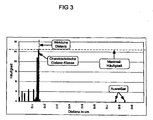
- Fig. 3 shows such a histogram with a fixed class width of 10 cm.
- the actual distance between the two mobile devices 10, 11 is 1.6 m in this example.
- the maximum frequency is 26 and is caused by the class, the minimum distance estimates between 1.5 m and 1.6 m aggregated.
- This distance class is also the characteristic distance class in this case.
- all distance classes that aggregate minimum distance estimates of higher distance have a much lower frequency than the maximum frequency.
- these distance classes are given a lower relevance and are not considered a characteristic distance class.
- the outliers on the right edge of the histogram are the result of measurement inaccuracies or other inadequacies, such as characterization errors or onset matching errors.
- the width of the classes of this histogram in meters will be set appropriately according to the task.
- the relevance of a class of a histogram thus generated depends on the frequency of the minimum distance estimates.
- a distance class which aggregates the largest minimum distance estimate between the two mobile devices 10, 11 to be located and at the same time still at least a predefined fraction of the maximum frequency of the histogram of all minimum -Distanzab houseen to each two objects 10, 11 has.
- a predefined fraction of the maximum frequency of the histogram of all minimum -Distanzab houseen to each two objects 10, 11 has.
- the relevance of a distance class can thus be determined by the upper limit of a distance class in meters, depending on whether the respective distance class still has a relevant frequency. If a distance class has a lower frequency than the required fraction of the maximum frequency, then it has the lowest relevance of 0.
- This grade estimates how robust or meaningful a total distance estimate thus obtained is for the subsequent topology reconstruction process (i.e., the location of the mobile devices 10, 11).
- the quality of the total distance estimate between two or more mobile devices 10, 11 depends on the shape of the set of minimum distance estimates. For more than two objects 10, 11, a suitable standard for the distances between the objects 10, 11, e.g. a minimum of individual grades used.
- a limit value is defined which determines from when an overall distance estimation has a sufficient quality.
- the quality of a total distance estimation is referred to below as estimation quality.
- estimation quality To determine the estimation quality, various heuristics are available.
- the quality of a total distance estimate can also be defined by the shape of a histogram, which is created for this purpose from a subset of the minimum distance estimates.
- the subset of the existing minimum distance estimates used for this purpose is determined by all minimum distance estimates which belong to the characteristic distance class or are smaller in their distance estimation.
- a histogram with N classes is formed.
- the class width is determined in this case so that the minimum distance estimate with the highest value is just placed in the last class.
- This resulting histogram is compared to a reference histogram.
- the reference histogram is the expected, perfect histogram with N classes, which assumes an equal distribution of the sound sources.
- the expected reference histogram is scaled so that the highest class has the same frequency as the created histogram.
- the sum of all deviations divided by the maximum possible deviation gives the quality of the total distance estimation.
- the maximum deviation is the sum all frequencies of the previously scaled expected reference histogram.
- the estimation quality can be used in many ways. For example, it may serve to ignore total distance estimates as long as they have insufficient quality. Another possibility is to take the goodness as relevance to topology reconstruction (i.e., localization).
- the relative positional image of the microphone devices 1 relative to one another can then be determined.
- Suitable methods for calculating the relative position of the microphone devices 1 or the mobile devices 10, 11 on the basis of the total distance estimates are, for example, mass-spring-spring simulations or the "multidimensional scaling".
- mass-spring simulation the individual mobile devices 10, 11 are represented as point masses.
- Each existing total distance estimate results in a spring between the two point masses with the length of the total distance estimate that these mobile devices 10, 11 represent. Iteratively, the energy of each spring is minimized until a stable balance is achieved. This last stable configuration will again interpreted as a relative situation image of the mobile devices 10, 11.
- the space for the previously described topology reconstruction i.e., the location of mobile devices 10, 11
- the space for the previously described topology reconstruction should also be 2-dimensional. If this is not the case, the reconstruction of the topology must work with 3-dimensional coordinates.
- Fig. 7 It is shown how the geometric arrangement of the acoustic source 3 relative to the two objects 10, 11 on the estimate of the distance A affects (see Fig. 1 for the geometric arrangement). Basically, any measurement of the acoustic signals has an error that is dependent on the relative location of the source 3 and the objects 10, 11.
- Fig. 7 the two objects 10, 11 are fixed and approximately centered in Fig. 7 shown.
- the quality of the measurement is shown in the form of isolines. If the acoustic source 3 and the two objects 10, 11 lie on a straight line and the source 3 does not lie exactly between the two objects 10, 11, the error is lowest, ie the quality of the measurement is close to 100%. At the other extreme, the acoustic source 3 lies on the mid-perpendicular between the objects 10, 20, so that the quality of the measurements here approaches 0. Between the extremes there is the in Fig. 7 displayed intermediate values.
- the invention is not limited in its execution to the above-mentioned preferred embodiments. Rather, a number of variants are conceivable that of the inventive method and the inventive Device even with fundamentally different types make use of.
Landscapes
- Physics & Mathematics (AREA)
- Engineering & Computer Science (AREA)
- General Physics & Mathematics (AREA)
- Radar, Positioning & Navigation (AREA)
- Remote Sensing (AREA)
- Measurement Of Velocity Or Position Using Acoustic Or Ultrasonic Waves (AREA)
Claims (12)
- Procédé d'estimation probable de la distance entre au moins un objet mobile (10) et au moins un autre objet mobile (11), les objets (10, 11) comprenant chacun un dispositif à microphone (1), dans lequela) au moins un signal acoustique (2) provenant d'au moins une source (3) est reçu avec les dispositifs à microphones (1) des objets (10, 11),b) le tracé en fonction du temps de chacun des signaux acoustiques (2) reçus fait l'objet d'une recherche automatique d'au moins un motif (5) avec un dispositif de traitement de données (4, 7) à l'aide de critères prédéterminés,c) l'au moins un motif (5) étant une amorce de l'au moins un signal acoustique (2) ou comprenant une amorce de l'au moins un signal acoustique (2) et l'amorce (5) étant un son, un bruit, un motif de son et/ou un motif de bruit qui provient de l'environnement des objets (10, 11), à savoir un bruit ambiant et/ou un son ambiant etd) en fonction temporelle de la réception de l'au moins un motif (5) à l'aide d'une synchronisation temporelle (6), par l'intermédiaire de laquelle les objets (10, 11) sont couplés, plus particulièrement par l'intermédiaire d'un signal radio, etune valeur est déterminée pour au moins une estimation de distance (Wegmin) entre les objets mobiles (10, 11), à l'aide de la différence de temps entre les au moins deux motifs (5), déterminés et considérés comme probablement identiques dans le signal acoustique, qui représente une distance (A) entre les au moins deux dispositifs à microphones (1) en tant qu'estimation de distance minimale,
caractérisé en ce quee) à l'aide du dispositif de traitement de données (4, 7), une analyse statistique est effectuée par l'intermédiaire d'une série d'estimations de distances minimales afin de déterminer l'estimation de distance la plus probable entre les objets (10, 11) et l'analyse statistique comprend une analyse d'une division en classes des mesures de distance, la fréquence maximale des estimations de distances minimales agrégées formant la classe de distance caractéristique. - Procédé selon la revendication 1, caractérisé en ce que l'au moins un objet est conçu comme un appareil mobile (10, 11), à savoir un téléphone mobile ou un ordinateur portable.
- Procédé selon la revendication 1 ou 2, caractérisé en ce que l'au moins un motif (5) est une amorce de l'au moins un signal acoustique (2), à savoir une variation brusque du volume sonore et/ou une variation de la pression acoustique après une phase préalable de silence relatif et/ou un signal généré sur la base de l'effet Doppler.
- Procédé selon au moins l'une des revendications précédentes, caractérisé en ce que le parcours a lieu selon l'au moins un motif (5) sur la base d'une propriété de l'au moins un signal acoustique (2) qui est indépendante du trajet de propagation du signal acoustique (2).
- Procédé selon au moins l'une des revendications précédentes, caractérisé en ce que l'au moins un motif (5) est détecté et/ou caractérisé par une analyse de fréquence, à l'aide d'une fréquence dominante, à l'aide de l'amplitude de l'au moins un signal acoustique (2), sur la base du nombre de passages à zéro, d'un codage de longueur de plage et/ou de la forme d'onde de l'au moins un signal acoustique (2).
- Procédé selon au moins l'une des revendications précédentes, caractérisé en ce que, à partir des données temporelles de l'arrivée de l'au moins un motif (5) et des temps de parcours différents qui en résultent pour au moins deux objets (10, 11), une distance (A) entre les deux objets (10, 11) est automatiquement déterminée.
- Dispositif d'estimation de la distance la plus probable entre au moins un objet mobile (10) et au moins un autre objet mobile (11), les objets (10) comprenant chacun un dispositif à microphone (1), avec lequel au moins un signal acoustique (2) provenant d'au moins une source acoustique (3) peut être reçu, avec un dispositif de traitement de données (4, 7) pour le parcours automatique du tracé temporel des signaux acoustiques (2) reçus, à l'aide de critères prédéterminés pour la détermination d'au moins un motif (5), avec un moyen pour la détection d'au moins un motif (5) de l'au moins un signal acoustique (2) avec au moins une amorce, l'amorce (5) étant un son, un bruit, un motif de son et/ou un motif de bruit, qui provient de l'environnement des objets (10, 11), à savoir un bruit ambiant et/ou un son ambiant, et un moyen d'estimation de la distance entre les objets (10, 11) en fonction de la réception de l'au moins un motif (5), les objets (10, 11) étant couplés par l'intermédiaire d'une synchronisation temporelle (6), plus particulièrement par l'intermédiaire d'un signal radio, une valeur pour l'au moins une estimation de distance (wegmin) entre les objets mobiles (10, 11) étant déterminée à l'aide d'au moins deux motifs (5), déterminés et considérés comme probablement identiques, dans le signal acoustique, qui représente une distance (A) entre les deux dispositifs à microphones (1) en tant qu'estimation de distance minimale,
caractérisé en ce que
un moyen d'analyse statistique d'une série d'estimations de distance minimales des objets (10, 11) pour la détermination de l'estimation de distance la plus probable entre les objets (10, 11), l'analyse statistique étant une analyse d'une division en classes des mesures de distances, la fréquence minimale des estimations de distances minimales agrégées représentant la classe de distance caractéristique. - Dispositif selon la revendication 7, caractérisé par un moyen de détection d'au moins un motif (5) de l'au moins un signal acoustique (2) avec une variation brusque du volume sonore et/ou une variation de la pression acoustique après une phase préalable de silence relatif et/ou d'un signal généré sur la base de l'effet Doppler.
- Dispositif selon la revendication 7 ou 8, caractérisé par un moyen de parcours, selon l'au moins un motif (5), sur la base d'une propriété de l'au moins un signal acoustique (2), la propriété étant indépendante du trajet de propagation du signal acoustique (2).
- Dispositif selon au moins l'une des revendications 7 à 9, caractérisé par un moyen d'analyse de fréquence de l'au moins un motif (5), à l'aide d'une fréquence dominante, de l'amplitude de l'au moins un signal acoustique (2) et/ou de la forme d'onde de l'au moins un signal acoustique (2).
- Dispositif selon au moins l'une des revendications 8 à 10, caractérisé en ce que, avec le dispositif de traitement de données (4, 7), une distance (A) entre les deux objets (10, 11) peut être déterminée automatiquement à partir des données temporelles de l'arrivée de l'au moins un motif (5) et des temps de parcours différents qui en résultent pour les au moins deux objets (10, 11).
- Dispositif selon au moins l'une des revendications 7 à 11, caractérisé en ce que l'au moins un objet est conçu comme un appareil mobile (10, 11), à savoir un téléphone mobile ou un ordinateur portable.
Applications Claiming Priority (2)
| Application Number | Priority Date | Filing Date | Title |
|---|---|---|---|
| DE102008021701A DE102008021701A1 (de) | 2008-04-28 | 2008-04-28 | Verfahren und Vorrichtung zur Lokalisation mindestens eines Gegenstandes |
| PCT/EP2009/055081 WO2009133078A1 (fr) | 2008-04-28 | 2009-04-27 | Procédé et dispositif de localisation d'au moins un objet |
Publications (2)
| Publication Number | Publication Date |
|---|---|
| EP2288932A1 EP2288932A1 (fr) | 2011-03-02 |
| EP2288932B1 true EP2288932B1 (fr) | 2015-08-19 |
Family
ID=40909915
Family Applications (1)
| Application Number | Title | Priority Date | Filing Date |
|---|---|---|---|
| EP09738122.2A Active EP2288932B1 (fr) | 2008-04-28 | 2009-04-27 | Procédé et appareil pour estimer la distance plus probable entre objets |
Country Status (6)
| Country | Link |
|---|---|
| US (1) | US8611188B2 (fr) |
| EP (1) | EP2288932B1 (fr) |
| CN (1) | CN102016632B (fr) |
| DE (1) | DE102008021701A1 (fr) |
| ES (1) | ES2548333T3 (fr) |
| WO (1) | WO2009133078A1 (fr) |
Families Citing this family (8)
| Publication number | Priority date | Publication date | Assignee | Title |
|---|---|---|---|---|
| US8855101B2 (en) * | 2010-03-09 | 2014-10-07 | The Nielsen Company (Us), Llc | Methods, systems, and apparatus to synchronize actions of audio source monitors |
| CN103645462B (zh) * | 2013-11-26 | 2015-08-12 | 清华大学 | 一种声波定位方法和终端 |
| WO2016123746A1 (fr) * | 2015-02-03 | 2016-08-11 | SZ DJI Technology Co., Ltd. | Système et procédé de détection de la position et de la vitesse d'un véhicule aérien par l'intermédiaire du son |
| DE102015212332A1 (de) * | 2015-07-01 | 2017-01-05 | Continental Automotive Gmbh | Verfahren zum automatisierten Führen eines Kraftfahrzeugs und Kraftfahrzeug zum Durchführen des Verfahrens |
| KR101892028B1 (ko) * | 2016-10-26 | 2018-08-27 | 현대자동차주식회사 | 음향 추적 정보 제공 방법, 차량용 음향 추적 장치, 및 이를 포함하는 차량 |
| DE102017205278A1 (de) * | 2017-03-29 | 2018-10-04 | Robert Bosch Gmbh | Verfahren zur Lokalisierung und Lokalisierungssystem mit einer Vorrichtung eingerichtet zur Lokalisierung |
| WO2019145923A2 (fr) | 2018-01-29 | 2019-08-01 | Wilfred Edwin Booij | Positionnement ad hoc de dispositifs mobiles à l'aide de signaux ultrasonores proches |
| CN112154345B (zh) | 2018-03-02 | 2024-08-16 | 所尼托技术股份公司 | 声学定位发射器和接收器系统及方法 |
Family Cites Families (8)
| Publication number | Priority date | Publication date | Assignee | Title |
|---|---|---|---|---|
| GB9314822D0 (en) * | 1993-07-17 | 1993-09-01 | Central Research Lab Ltd | Determination of position |
| AU1290401A (en) * | 1999-11-11 | 2001-06-06 | Scientific Generics Limited | Acoustic location system |
| EP2288121A3 (fr) * | 2000-11-30 | 2011-06-22 | Intrasonics S.A.R.L. | Dispositif de télécommunication opérant de manière intéractive avec une transmission audio |
| US6792118B2 (en) * | 2001-11-14 | 2004-09-14 | Applied Neurosystems Corporation | Computation of multi-sensor time delays |
| NO318010B1 (no) * | 2002-12-04 | 2005-01-17 | Sonitor Technologies As | Ultralyd lokaliseringssystem |
| US6941246B2 (en) * | 2003-09-18 | 2005-09-06 | Intel Corporation | Method for three-dimensional position calibration of audio sensors and actuators on a distributed computing platform |
| JP4568641B2 (ja) * | 2005-05-27 | 2010-10-27 | 株式会社日立製作所 | 無線通信システム、ノード位置算出方法及びノード |
| US7738884B2 (en) | 2005-06-28 | 2010-06-15 | Microsoft Corporation | Positioning service utilizing existing radio base stations |
-
2008
- 2008-04-28 DE DE102008021701A patent/DE102008021701A1/de not_active Withdrawn
-
2009
- 2009-04-27 US US12/989,913 patent/US8611188B2/en not_active Expired - Fee Related
- 2009-04-27 WO PCT/EP2009/055081 patent/WO2009133078A1/fr not_active Ceased
- 2009-04-27 EP EP09738122.2A patent/EP2288932B1/fr active Active
- 2009-04-27 ES ES09738122.2T patent/ES2548333T3/es active Active
- 2009-04-27 CN CN200980115776.5A patent/CN102016632B/zh not_active Expired - Fee Related
Also Published As
| Publication number | Publication date |
|---|---|
| ES2548333T3 (es) | 2015-10-15 |
| US8611188B2 (en) | 2013-12-17 |
| CN102016632A (zh) | 2011-04-13 |
| EP2288932A1 (fr) | 2011-03-02 |
| DE102008021701A1 (de) | 2009-10-29 |
| CN102016632B (zh) | 2014-03-12 |
| WO2009133078A1 (fr) | 2009-11-05 |
| US20110182148A1 (en) | 2011-07-28 |
Similar Documents
| Publication | Publication Date | Title |
|---|---|---|
| WO2009133078A1 (fr) | Procédé et dispositif de localisation d'au moins un objet | |
| DE102016114751B4 (de) | Bewertung der Fahreraufmerksamkeit | |
| DE102015006931B4 (de) | Parkzonen-Erkennungsvorrichtung und Steuerungsverfahren davon | |
| WO2017001607A1 (fr) | Procédé et dispositif pour créer une base de données | |
| DE102015006032B4 (de) | Ultraschalldetektionseinrichtung und Detektionsverfahren dafür | |
| DE102009047012A1 (de) | Verfahren zur Erfassung von Objekten | |
| DE102020214847A1 (de) | Allophon-inspektionsvorrichtung und inspektionsverfahren davon | |
| WO2019141648A1 (fr) | Procédé et dispositif pour faire fonctionner un capteur acoustique | |
| DE102021103324A1 (de) | Erkennung von objektbewegung auf basis der analyse von ultraschallsensordaten | |
| DE60301146T2 (de) | Verfahren und system zum repräsentieren eines schallfeldes | |
| DE112015004210T5 (de) | Ultraschalllokalisierung verschachtelt mit alternierenden audiofunktionen | |
| EP4445174A1 (fr) | Procédé de relevé d'environnement d'un véhicule automobile | |
| DE102014213122B4 (de) | Vorrichtung und Verfahren zur schallbasierten Umfelddetektion | |
| DE102021103340A1 (de) | Erkennung von objektbewegung auf basis der analyse von ultraschallsensordaten | |
| EP1352375B1 (fr) | Procede et dispositif pour evaluer des parametres de mouvement de cibles | |
| DE112022003614B4 (de) | Doppelseitiges Zwei-Wege-Abstandsmessungsprotokoll auf Grundlage von zusammengesetzten Ultraschalltönen | |
| DE102022201395B4 (de) | Ermitteln einer Ursprungsrichtung von Schallsignalen | |
| DE102019211404A1 (de) | Verfahren zur Bestimmung einer Einfallsrichtung einer Sondersignal-Schallquelle | |
| DE112024000398T5 (de) | Beobachtungszielerfassungsvorrichtung und Beobachtungszielerfassungsverfahren | |
| DE102016211827B4 (de) | Verfahren zur Ermittlung einer eine relative Position zwischen zwei relativ zueinander bewegbaren Einheiten beschreibenden Positionsinformation, Positionsbestimmungssystem und medizinische Einrichtung | |
| DE102017205278A1 (de) | Verfahren zur Lokalisierung und Lokalisierungssystem mit einer Vorrichtung eingerichtet zur Lokalisierung | |
| EP1480182B1 (fr) | Compteur d'essieux sans contact pour traffic routier | |
| DE10310857A1 (de) | Positions-Messsystem | |
| EP4086869A1 (fr) | Procédé et dispositif de détection et de localisation d'un point de défaillance d'un logement | |
| EP4176285B1 (fr) | Détermination de direction de vitesse basée sur l'effet doppler |
Legal Events
| Date | Code | Title | Description |
|---|---|---|---|
| PUAI | Public reference made under article 153(3) epc to a published international application that has entered the european phase |
Free format text: ORIGINAL CODE: 0009012 |
|
| 17P | Request for examination filed |
Effective date: 20101126 |
|
| AK | Designated contracting states |
Kind code of ref document: A1 Designated state(s): AT BE BG CH CY CZ DE DK EE ES FI FR GB GR HR HU IE IS IT LI LT LU LV MC MK MT NL NO PL PT RO SE SI SK TR |
|
| AX | Request for extension of the european patent |
Extension state: AL BA RS |
|
| DAX | Request for extension of the european patent (deleted) | ||
| 17Q | First examination report despatched |
Effective date: 20120925 |
|
| REG | Reference to a national code |
Ref country code: DE Ref legal event code: R079 Ref document number: 502009011437 Country of ref document: DE Free format text: PREVIOUS MAIN CLASS: G01S0005300000 Ipc: G01S0015020000 |
|
| GRAP | Despatch of communication of intention to grant a patent |
Free format text: ORIGINAL CODE: EPIDOSNIGR1 |
|
| INTG | Intention to grant announced |
Effective date: 20150205 |
|
| RIC1 | Information provided on ipc code assigned before grant |
Ipc: G01S 11/14 20060101ALI20150123BHEP Ipc: G01S 5/02 20100101ALI20150123BHEP Ipc: G01S 15/02 20060101AFI20150123BHEP |
|
| GRAP | Despatch of communication of intention to grant a patent |
Free format text: ORIGINAL CODE: EPIDOSNIGR1 |
|
| INTG | Intention to grant announced |
Effective date: 20150414 |
|
| GRAS | Grant fee paid |
Free format text: ORIGINAL CODE: EPIDOSNIGR3 |
|
| GRAA | (expected) grant |
Free format text: ORIGINAL CODE: 0009210 |
|
| AK | Designated contracting states |
Kind code of ref document: B1 Designated state(s): AT BE BG CH CY CZ DE DK EE ES FI FR GB GR HR HU IE IS IT LI LT LU LV MC MK MT NL NO PL PT RO SE SI SK TR |
|
| REG | Reference to a national code |
Ref country code: GB Ref legal event code: FG4D Free format text: NOT ENGLISH |
|
| REG | Reference to a national code |
Ref country code: CH Ref legal event code: EP |
|
| REG | Reference to a national code |
Ref country code: IE Ref legal event code: FG4D Free format text: LANGUAGE OF EP DOCUMENT: GERMAN |
|
| REG | Reference to a national code |
Ref country code: AT Ref legal event code: REF Ref document number: 744198 Country of ref document: AT Kind code of ref document: T Effective date: 20150915 |
|
| REG | Reference to a national code |
Ref country code: DE Ref legal event code: R096 Ref document number: 502009011437 Country of ref document: DE |
|
| REG | Reference to a national code |
Ref country code: ES Ref legal event code: FG2A Ref document number: 2548333 Country of ref document: ES Kind code of ref document: T3 Effective date: 20151015 |
|
| REG | Reference to a national code |
Ref country code: LT Ref legal event code: MG4D |
|
| REG | Reference to a national code |
Ref country code: NL Ref legal event code: MP Effective date: 20150819 |
|
| PG25 | Lapsed in a contracting state [announced via postgrant information from national office to epo] |
Ref country code: NO Free format text: LAPSE BECAUSE OF FAILURE TO SUBMIT A TRANSLATION OF THE DESCRIPTION OR TO PAY THE FEE WITHIN THE PRESCRIBED TIME-LIMIT Effective date: 20151119 Ref country code: LV Free format text: LAPSE BECAUSE OF FAILURE TO SUBMIT A TRANSLATION OF THE DESCRIPTION OR TO PAY THE FEE WITHIN THE PRESCRIBED TIME-LIMIT Effective date: 20150819 Ref country code: LT Free format text: LAPSE BECAUSE OF FAILURE TO SUBMIT A TRANSLATION OF THE DESCRIPTION OR TO PAY THE FEE WITHIN THE PRESCRIBED TIME-LIMIT Effective date: 20150819 Ref country code: GR Free format text: LAPSE BECAUSE OF FAILURE TO SUBMIT A TRANSLATION OF THE DESCRIPTION OR TO PAY THE FEE WITHIN THE PRESCRIBED TIME-LIMIT Effective date: 20151120 |
|
| PG25 | Lapsed in a contracting state [announced via postgrant information from national office to epo] |
Ref country code: SE Free format text: LAPSE BECAUSE OF FAILURE TO SUBMIT A TRANSLATION OF THE DESCRIPTION OR TO PAY THE FEE WITHIN THE PRESCRIBED TIME-LIMIT Effective date: 20150819 Ref country code: PL Free format text: LAPSE BECAUSE OF FAILURE TO SUBMIT A TRANSLATION OF THE DESCRIPTION OR TO PAY THE FEE WITHIN THE PRESCRIBED TIME-LIMIT Effective date: 20150819 Ref country code: PT Free format text: LAPSE BECAUSE OF FAILURE TO SUBMIT A TRANSLATION OF THE DESCRIPTION OR TO PAY THE FEE WITHIN THE PRESCRIBED TIME-LIMIT Effective date: 20151221 Ref country code: IS Free format text: LAPSE BECAUSE OF FAILURE TO SUBMIT A TRANSLATION OF THE DESCRIPTION OR TO PAY THE FEE WITHIN THE PRESCRIBED TIME-LIMIT Effective date: 20151219 |
|
| PG25 | Lapsed in a contracting state [announced via postgrant information from national office to epo] |
Ref country code: NL Free format text: LAPSE BECAUSE OF FAILURE TO SUBMIT A TRANSLATION OF THE DESCRIPTION OR TO PAY THE FEE WITHIN THE PRESCRIBED TIME-LIMIT Effective date: 20150819 |
|
| REG | Reference to a national code |
Ref country code: FR Ref legal event code: PLFP Year of fee payment: 8 |
|
| PG25 | Lapsed in a contracting state [announced via postgrant information from national office to epo] |
Ref country code: IT Free format text: LAPSE BECAUSE OF FAILURE TO SUBMIT A TRANSLATION OF THE DESCRIPTION OR TO PAY THE FEE WITHIN THE PRESCRIBED TIME-LIMIT Effective date: 20150819 Ref country code: CZ Free format text: LAPSE BECAUSE OF FAILURE TO SUBMIT A TRANSLATION OF THE DESCRIPTION OR TO PAY THE FEE WITHIN THE PRESCRIBED TIME-LIMIT Effective date: 20150819 Ref country code: SK Free format text: LAPSE BECAUSE OF FAILURE TO SUBMIT A TRANSLATION OF THE DESCRIPTION OR TO PAY THE FEE WITHIN THE PRESCRIBED TIME-LIMIT Effective date: 20150819 Ref country code: EE Free format text: LAPSE BECAUSE OF FAILURE TO SUBMIT A TRANSLATION OF THE DESCRIPTION OR TO PAY THE FEE WITHIN THE PRESCRIBED TIME-LIMIT Effective date: 20150819 Ref country code: DK Free format text: LAPSE BECAUSE OF FAILURE TO SUBMIT A TRANSLATION OF THE DESCRIPTION OR TO PAY THE FEE WITHIN THE PRESCRIBED TIME-LIMIT Effective date: 20150819 |
|
| REG | Reference to a national code |
Ref country code: DE Ref legal event code: R097 Ref document number: 502009011437 Country of ref document: DE |
|
| PG25 | Lapsed in a contracting state [announced via postgrant information from national office to epo] |
Ref country code: RO Free format text: LAPSE BECAUSE OF FAILURE TO SUBMIT A TRANSLATION OF THE DESCRIPTION OR TO PAY THE FEE WITHIN THE PRESCRIBED TIME-LIMIT Effective date: 20150819 |
|
| PLBE | No opposition filed within time limit |
Free format text: ORIGINAL CODE: 0009261 |
|
| STAA | Information on the status of an ep patent application or granted ep patent |
Free format text: STATUS: NO OPPOSITION FILED WITHIN TIME LIMIT |
|
| 26N | No opposition filed |
Effective date: 20160520 |
|
| PG25 | Lapsed in a contracting state [announced via postgrant information from national office to epo] |
Ref country code: BE Free format text: LAPSE BECAUSE OF NON-PAYMENT OF DUE FEES Effective date: 20160430 Ref country code: SI Free format text: LAPSE BECAUSE OF FAILURE TO SUBMIT A TRANSLATION OF THE DESCRIPTION OR TO PAY THE FEE WITHIN THE PRESCRIBED TIME-LIMIT Effective date: 20150819 |
|
| REG | Reference to a national code |
Ref country code: CH Ref legal event code: PL |
|
| PG25 | Lapsed in a contracting state [announced via postgrant information from national office to epo] |
Ref country code: LU Free format text: LAPSE BECAUSE OF FAILURE TO SUBMIT A TRANSLATION OF THE DESCRIPTION OR TO PAY THE FEE WITHIN THE PRESCRIBED TIME-LIMIT Effective date: 20160427 |
|
| REG | Reference to a national code |
Ref country code: IE Ref legal event code: MM4A |
|
| PG25 | Lapsed in a contracting state [announced via postgrant information from national office to epo] |
Ref country code: CH Free format text: LAPSE BECAUSE OF NON-PAYMENT OF DUE FEES Effective date: 20160430 Ref country code: LI Free format text: LAPSE BECAUSE OF NON-PAYMENT OF DUE FEES Effective date: 20160430 |
|
| REG | Reference to a national code |
Ref country code: FR Ref legal event code: PLFP Year of fee payment: 9 |
|
| PG25 | Lapsed in a contracting state [announced via postgrant information from national office to epo] |
Ref country code: IE Free format text: LAPSE BECAUSE OF NON-PAYMENT OF DUE FEES Effective date: 20160427 |
|
| REG | Reference to a national code |
Ref country code: FR Ref legal event code: PLFP Year of fee payment: 10 |
|
| PG25 | Lapsed in a contracting state [announced via postgrant information from national office to epo] |
Ref country code: CY Free format text: LAPSE BECAUSE OF FAILURE TO SUBMIT A TRANSLATION OF THE DESCRIPTION OR TO PAY THE FEE WITHIN THE PRESCRIBED TIME-LIMIT Effective date: 20150819 Ref country code: HU Free format text: LAPSE BECAUSE OF FAILURE TO SUBMIT A TRANSLATION OF THE DESCRIPTION OR TO PAY THE FEE WITHIN THE PRESCRIBED TIME-LIMIT; INVALID AB INITIO Effective date: 20090427 |
|
| PG25 | Lapsed in a contracting state [announced via postgrant information from national office to epo] |
Ref country code: HR Free format text: LAPSE BECAUSE OF FAILURE TO SUBMIT A TRANSLATION OF THE DESCRIPTION OR TO PAY THE FEE WITHIN THE PRESCRIBED TIME-LIMIT Effective date: 20150819 Ref country code: MT Free format text: LAPSE BECAUSE OF FAILURE TO SUBMIT A TRANSLATION OF THE DESCRIPTION OR TO PAY THE FEE WITHIN THE PRESCRIBED TIME-LIMIT Effective date: 20150819 Ref country code: MC Free format text: LAPSE BECAUSE OF FAILURE TO SUBMIT A TRANSLATION OF THE DESCRIPTION OR TO PAY THE FEE WITHIN THE PRESCRIBED TIME-LIMIT Effective date: 20150819 Ref country code: MK Free format text: LAPSE BECAUSE OF FAILURE TO SUBMIT A TRANSLATION OF THE DESCRIPTION OR TO PAY THE FEE WITHIN THE PRESCRIBED TIME-LIMIT Effective date: 20150819 Ref country code: TR Free format text: LAPSE BECAUSE OF FAILURE TO SUBMIT A TRANSLATION OF THE DESCRIPTION OR TO PAY THE FEE WITHIN THE PRESCRIBED TIME-LIMIT Effective date: 20150819 |
|
| PG25 | Lapsed in a contracting state [announced via postgrant information from national office to epo] |
Ref country code: BG Free format text: LAPSE BECAUSE OF FAILURE TO SUBMIT A TRANSLATION OF THE DESCRIPTION OR TO PAY THE FEE WITHIN THE PRESCRIBED TIME-LIMIT Effective date: 20150819 |
|
| PGFP | Annual fee paid to national office [announced via postgrant information from national office to epo] |
Ref country code: ES Payment date: 20190603 Year of fee payment: 13 |
|
| PGFP | Annual fee paid to national office [announced via postgrant information from national office to epo] |
Ref country code: FR Payment date: 20190423 Year of fee payment: 11 |
|
| PGFP | Annual fee paid to national office [announced via postgrant information from national office to epo] |
Ref country code: AT Payment date: 20190416 Year of fee payment: 11 Ref country code: GB Payment date: 20190424 Year of fee payment: 11 |
|
| REG | Reference to a national code |
Ref country code: FI Ref legal event code: MAE |
|
| REG | Reference to a national code |
Ref country code: AT Ref legal event code: MM01 Ref document number: 744198 Country of ref document: AT Kind code of ref document: T Effective date: 20200427 |
|
| PG25 | Lapsed in a contracting state [announced via postgrant information from national office to epo] |
Ref country code: AT Free format text: LAPSE BECAUSE OF NON-PAYMENT OF DUE FEES Effective date: 20200427 Ref country code: FI Free format text: LAPSE BECAUSE OF NON-PAYMENT OF DUE FEES Effective date: 20200427 Ref country code: FR Free format text: LAPSE BECAUSE OF NON-PAYMENT OF DUE FEES Effective date: 20200430 |
|
| GBPC | Gb: european patent ceased through non-payment of renewal fee |
Effective date: 20200427 |
|
| PG25 | Lapsed in a contracting state [announced via postgrant information from national office to epo] |
Ref country code: GB Free format text: LAPSE BECAUSE OF NON-PAYMENT OF DUE FEES Effective date: 20200427 |
|
| REG | Reference to a national code |
Ref country code: ES Ref legal event code: FD2A Effective date: 20210906 |
|
| PG25 | Lapsed in a contracting state [announced via postgrant information from national office to epo] |
Ref country code: ES Free format text: LAPSE BECAUSE OF NON-PAYMENT OF DUE FEES Effective date: 20200428 |
|
| P01 | Opt-out of the competence of the unified patent court (upc) registered |
Effective date: 20230524 |
|
| PGFP | Annual fee paid to national office [announced via postgrant information from national office to epo] |
Ref country code: DE Payment date: 20250417 Year of fee payment: 17 |