EP2289145B1 - Procédé de réglage pour une installation de transmission de courant continu haute tension présentant un circuit intermédiaire à courant continu et des convertisseurs automatiques - Google Patents
Procédé de réglage pour une installation de transmission de courant continu haute tension présentant un circuit intermédiaire à courant continu et des convertisseurs automatiques Download PDFInfo
- Publication number
- EP2289145B1 EP2289145B1 EP08773688.0A EP08773688A EP2289145B1 EP 2289145 B1 EP2289145 B1 EP 2289145B1 EP 08773688 A EP08773688 A EP 08773688A EP 2289145 B1 EP2289145 B1 EP 2289145B1
- Authority
- EP
- European Patent Office
- Prior art keywords
- voltage
- idc
- rectifier
- direct current
- nominal
- Prior art date
- Legal status (The legal status is an assumption and is not a legal conclusion. Google has not performed a legal analysis and makes no representation as to the accuracy of the status listed.)
- Active
Links
Images


Classifications
-
- H—ELECTRICITY
- H02—GENERATION; CONVERSION OR DISTRIBUTION OF ELECTRIC POWER
- H02J—ELECTRIC POWER NETWORKS; CIRCUIT ARRANGEMENTS OR SYSTEMS FOR SUPPLYING OR DISTRIBUTING ELECTRIC POWER; SYSTEMS FOR STORING ELECTRIC ENERGY
- H02J3/00—Circuit arrangements for AC mains or AC distribution networks
- H02J3/36—Arrangements for transfer of electric power between AC networks via high-voltage DC [HVDC] links; Arrangements for transfer of electric power between generators and networks via HVDC links
-
- H—ELECTRICITY
- H02—GENERATION; CONVERSION OR DISTRIBUTION OF ELECTRIC POWER
- H02M—APPARATUS FOR CONVERSION BETWEEN AC AND AC, BETWEEN AC AND DC, OR BETWEEN DC AND DC, AND FOR USE WITH MAINS OR SIMILAR POWER SUPPLY SYSTEMS; CONVERSION OF DC OR AC INPUT POWER INTO SURGE OUTPUT POWER; CONTROL OR REGULATION THEREOF
- H02M5/00—Conversion of AC power input into AC power output, e.g. for change of voltage, for change of frequency, for change of number of phases
- H02M5/40—Conversion of AC power input into AC power output, e.g. for change of voltage, for change of frequency, for change of number of phases with intermediate conversion into DC
- H02M5/42—Conversion of AC power input into AC power output, e.g. for change of voltage, for change of frequency, for change of number of phases with intermediate conversion into DC by static converters
- H02M5/44—Conversion of AC power input into AC power output, e.g. for change of voltage, for change of frequency, for change of number of phases with intermediate conversion into DC by static converters using discharge tubes or semiconductor devices to convert the intermediate DC into AC
- H02M5/453—Conversion of AC power input into AC power output, e.g. for change of voltage, for change of frequency, for change of number of phases with intermediate conversion into DC by static converters using discharge tubes or semiconductor devices to convert the intermediate DC into AC using devices of a triode or transistor type requiring continuous application of a control signal
- H02M5/458—Conversion of AC power input into AC power output, e.g. for change of voltage, for change of frequency, for change of number of phases with intermediate conversion into DC by static converters using discharge tubes or semiconductor devices to convert the intermediate DC into AC using devices of a triode or transistor type requiring continuous application of a control signal using semiconductor devices only
- H02M5/4585—Conversion of AC power input into AC power output, e.g. for change of voltage, for change of frequency, for change of number of phases with intermediate conversion into DC by static converters using discharge tubes or semiconductor devices to convert the intermediate DC into AC using devices of a triode or transistor type requiring continuous application of a control signal using semiconductor devices only having a rectifier with controlled elements
-
- H—ELECTRICITY
- H02—GENERATION; CONVERSION OR DISTRIBUTION OF ELECTRIC POWER
- H02M—APPARATUS FOR CONVERSION BETWEEN AC AND AC, BETWEEN AC AND DC, OR BETWEEN DC AND DC, AND FOR USE WITH MAINS OR SIMILAR POWER SUPPLY SYSTEMS; CONVERSION OF DC OR AC INPUT POWER INTO SURGE OUTPUT POWER; CONTROL OR REGULATION THEREOF
- H02M7/00—Conversion of AC power input into DC power output; Conversion of DC power input into AC power output
- H02M7/42—Conversion of DC power input into AC power output without possibility of reversal
- H02M7/44—Conversion of DC power input into AC power output without possibility of reversal by static converters
- H02M7/48—Conversion of DC power input into AC power output without possibility of reversal by static converters using discharge tubes with control electrode or semiconductor devices with control electrode
- H02M7/483—Converters with outputs that each can have more than two voltages levels
- H02M7/4835—Converters with outputs that each can have more than two voltages levels comprising two or more cells, each including a switchable capacitor, the capacitors having a nominal charge voltage which corresponds to a given fraction of the input voltage, and the capacitors being selectively connected in series to determine the instantaneous output voltage
-
- H—ELECTRICITY
- H02—GENERATION; CONVERSION OR DISTRIBUTION OF ELECTRIC POWER
- H02M—APPARATUS FOR CONVERSION BETWEEN AC AND AC, BETWEEN AC AND DC, OR BETWEEN DC AND DC, AND FOR USE WITH MAINS OR SIMILAR POWER SUPPLY SYSTEMS; CONVERSION OF DC OR AC INPUT POWER INTO SURGE OUTPUT POWER; CONTROL OR REGULATION THEREOF
- H02M7/00—Conversion of AC power input into DC power output; Conversion of DC power input into AC power output
- H02M7/66—Conversion of AC power input into DC power output; Conversion of DC power input into AC power output with possibility of reversal
- H02M7/68—Conversion of AC power input into DC power output; Conversion of DC power input into AC power output with possibility of reversal by static converters
- H02M7/72—Conversion of AC power input into DC power output; Conversion of DC power input into AC power output with possibility of reversal by static converters using discharge tubes with control electrode or semiconductor devices with control electrode
- H02M7/75—Conversion of AC power input into DC power output; Conversion of DC power input into AC power output with possibility of reversal by static converters using discharge tubes with control electrode or semiconductor devices with control electrode using devices of a thyratron or thyristor type requiring extinguishing means
- H02M7/757—Conversion of AC power input into DC power output; Conversion of DC power input into AC power output with possibility of reversal by static converters using discharge tubes with control electrode or semiconductor devices with control electrode using devices of a thyratron or thyristor type requiring extinguishing means using semiconductor devices only
- H02M7/7575—Conversion of AC power input into DC power output; Conversion of DC power input into AC power output with possibility of reversal by static converters using discharge tubes with control electrode or semiconductor devices with control electrode using devices of a thyratron or thyristor type requiring extinguishing means using semiconductor devices only for high voltage direct transmission link
-
- Y—GENERAL TAGGING OF NEW TECHNOLOGICAL DEVELOPMENTS; GENERAL TAGGING OF CROSS-SECTIONAL TECHNOLOGIES SPANNING OVER SEVERAL SECTIONS OF THE IPC; TECHNICAL SUBJECTS COVERED BY FORMER USPC CROSS-REFERENCE ART COLLECTIONS [XRACs] AND DIGESTS
- Y02—TECHNOLOGIES OR APPLICATIONS FOR MITIGATION OR ADAPTATION AGAINST CLIMATE CHANGE
- Y02E—REDUCTION OF GREENHOUSE GAS [GHG] EMISSIONS, RELATED TO ENERGY GENERATION, TRANSMISSION OR DISTRIBUTION
- Y02E60/00—Enabling technologies; Technologies with a potential or indirect contribution to GHG emissions mitigation
- Y02E60/60—Arrangements for transfer of electric power between AC networks or generators via a high voltage DC link [HVCD]
Definitions
- the invention relates to a method for controlling at least two converters, which are controllable as rectifiers or inverters and connected to one another via a DC voltage connection, in the field of energy transmission and / or distribution, wherein at each inverter in each case a DC measurement voltage (Udc_r1 ... Udc_rr Udc_i1 ... Udc_ii) and in each case a DC measurement current (Idc_r1 ... Idc_rr; Idc_i1 ...
- Idc_ii are measured and transmitted to a rectifier control for controlling the respective rectifier or to an inverter control for controlling the respective associated inverter, each Rectifier control and each inverter control in each case the difference between a predetermined setpoint DC voltage (Udco) and the respectively received DC measurement voltage (Udc_r1 ... Udc_rr, Udc_i1 ... Udc_ii) to obtain a differential DC voltage (du) and further the difference between a DC reference current (Idco_r1 .. Idco_rr, Idco_i1 ... Idco_ii) and the j in each case receive the measured direct current (Idc_r1 ... Idc_rr, Idc_i1 ... Idc_ii) while obtaining a differential direct current (di), whereby the measured direct current, the measured direct voltage, the nominal direct current and the nominal direct voltage are normalized,
- High-voltage direct current (HVDC) transmission system consists of a rectifier and an inverter, which are connected to each other via a direct current connection. Transformers are provided for coupling the inverters to the respectively assigned AC voltage grid.
- a DC measurement voltage Udc_r or Udc_i and in each case a DC measurement current Idc_r or Idc_i are detected both at the rectifier and at the inverter and transmitted to the respective control.
- a setpoint DC voltage Udco and a setpoint DC current Idco are determined with the aid of a function generator.
- the differential DC voltage du is calculated from the difference between the desired DC voltage Udco and the DC measurement voltage Udc_r, Udc_i.
- the differential direct current di is formed from the difference of the nominal direct current Idco and the respectively determined measured direct current Idc_r and Idc_i. All values are normalized in this case, wherein, for example, normalized to a nominal DC voltage and a nominal DC current or else to nominal DC current and the nominal DC voltage.
- the rectifier control regulates the rectifier in such a way that the sum of the differential DC voltage du and the differential direct current di becomes minimal.
- the inverter control regulates the inverter in such a way that the difference between the differential direct current di and the differential DC voltage du becomes minimal.
- DE 195 44 777 C1 a similar method is disclosed.
- the previously known method is only suitable for so-called externally controlled converters in which, for example, thyristors, which can not be switched off by means of ignition signals, are used.
- Such converters allow a current flow in the DC circuit in only one direction. A reversal of the power flow can only take place by reversing the polarity of the voltage drop across the respective converter.
- the operating current in this system which is referred to hereafter as classical HVDC, must always be greater than 0.05 pu due to the required gap current avoidance of the current setpoint. This allows the above normalization to the setpoints.
- VSC Voltage Source Converter
- the object of the invention is to provide a method of the type mentioned above, with which a control of converters having turn-off power semiconductor and connected to each other via a DC voltage intermediate circuit are, can be performed, at the same time the setting of desired currents equal to zero is possible.
- each converter is a self-commutated converter (1) with turn-off power semiconductors and the rectifier control regulates the respectively assigned converter so that the sum of the product of the differential direct voltage (du) and the amount of the respectively assigned rectifier Nominal direct current (
- the invention transfers the control method known from the classical HVDC to HVDC systems in which VSCs and DC intermediate circuits are used. Due to the DC intermediate circuit, voltage reversal can no longer take place in these so-called Voltage Source Converters (VSC), which causes a reversal of the power flow in the case of classic HVDC. The inversion of the power flow occurs in such converters (VSCs) by a reversal of the current flow.
- VSCs Voltage Source Converters
- the method according to the invention also allows the specification of nominal currents in the value of zero. This was impossible with the known control methods for classical HVDC.
- the method according to the invention thus provides a simple and flexible control of two or more VSCs which are connected to one another via a DC voltage connection.
- the DC voltage connection has a polarity which does not change during the operation of the HVDC system within the scope of the invention, even with a reversal of the power flow.
- the DC voltage connection is for example a bipolar DC voltage connection, which extends between two inverters.
- the HVDC system to be controlled consists of a rectifier, which is connected via an inductance, for example a transformer, to an AC voltage supply network providing energy.
- the inverter which is connected via the bipolar DC connection to the said rectifier, is also connected via an inductance, such as a transformer, to a second AC voltage network having, for example, the loads to be supplied.
- a plurality of converters can also be regulated in accordance with the method according to the invention, the converters or, in this case, the VSCs being connected to one another via a DC voltage connection having an arbitrary topology.
- the method according to the invention is completely independent of the topology of the DC connection.
- the inverter are at least 1 kilometer away from each other.
- the so-called back-to-back configuration in which inverter and inverter are placed spatially side by side and only to controllable Coupling different AC networks serve, excluded.
- the device for which the method according to this advantageous development is designed, thus serves for the transmission of electrical energy over a greater distance.
- each DC measurement voltage Udc_rr or Udc_ii and the desired DC voltage Udco are normalized to the desired DC voltage Udco.
- this standardization which is already known from classical HVDC, takes place only in connection with the respective measured and nominal DC voltage.
- normalization to the desired direct current is omitted in order to enable the use of nominal direct currents equal to zero even in this expedient further development of the invention.
- two inverters are provided, one of which is operated as a rectifier and the other as an inverter, wherein extending between the rectifier and the inverter DC voltage intermediate circuit.
- the method is used for an HVDC system with VSCs and an unbranched DC voltage intermediate circuit.
- the DC voltage intermediate circuit is designed, for example, unipolar, wherein the earth is used as a return conductor.
- the DC voltage connection is two-pole, whereby positive pole and negative pole of the DC voltage connection are realized in the form of cable ladders.
- the method according to the invention is provided for at least three inverters, between which a DC voltage grid extends.
- the DC voltage network can have any desired topology.
- each rectifier control and for each inverter control in each case an associated rectifier setpoint DC power (Pdco_r1 ... Pdco_rr) or inverter setpoint DC power (Pdco_i1 ... Pdco_ii) is determined, the sum of all rectifier set DC power and all Inticianersollmaschinen is equal to zero.
- the respective nominal equal powers are determined, for example, by a central control center and transmitted from there to the respective converter regulations. For transmission is by no means an efficient communication link necessary, as is the case for example with the classical HVDC. In the context of the invention, it is sufficient to transmit the respective nominal equal power over the Internet or any other simple and thus cost-effective telecommunications to the respective scheme.
- the setpoint direct current assigned to the converter is determined on each converter from the setpoint direct power assigned to it and the general setpoint DC voltage. According to this advantageous further development, the method according to the invention is designed simply and clearly.
- each rectifier and each inverter over the entire working range of the rectifier or the inverter away both on the basis of the respectively associated rectifier differential direct current (di_r1 ... di_rr) and on the basis of the rectifier differential DC voltage (du_r1 ... du_rr) or on the basis of each associated inverter difference direct current (di_r1 ... di_rr) as well as on the basis of the associated inverter differential DC voltage (du_i1 ... du_ii) takes place.
- a DC measuring voltage (Udc_r1 ... Udc_rr; Udc_i1 ... Udc_ii) and in each case one measuring direct current (Idc_r1 ... Idc_rr; Idc_i1 ... Idc_ii) are measured and transmitted to a rectifier control or an inverter control.
- a number of inverters are regulated such that a direct current flowing through a circuit breaker arranged in the DC connection becomes zero.
- simple circuit breakers can be used in the DC connection, since switching can always be made without current.
- At least one converter will control the measured direct current detected in each case to zero, and then at least one disconnecting switch arranged in the direct voltage connection will open.
- the zero-current control takes place with the aid of the use of a nominal direct current equal to zero.
- all converters which are connected to one another by a DC voltage connection are regulated to zero. In other words, a nominal DC current of zero is used at each control.
- a switch-off instant is set and transmitted to the respectively affected control unit, said control unit, when reaching the switch-off instant, regulating its associated DC measurement current to zero.
- all control units have a time signal generator, for example an accurate clock, which provides a common or substantially common time signal for all controls. This time signal is compared with the set and transmitted switch-off time. If the difference between the switch-off time and the measured time falls below a preset threshold value, ie when the switch-off time is reached, the respective control unit is given a nominal direct current of zero, so that the measured direct current is regulated to zero.
- a preset threshold value ie when the switch-off time is reached
- the DC measuring current is regulated to zero by each affected converter over a zero-current duration, with the usual control method subsequently being started again, ie after the zero-current period has expired.
- the zero-current period which is for example in the range of a few milliseconds, the opening of the desired disconnector or switches in the DC voltage connection now takes place.
- FIG. 1 schematically shows an HVDC system with a plurality of converters 1, which are each connected via a transformer 2 with an AC voltage network 3.
- Each inverter 1 is a so-called Voltage Source Converter (VSC), with turn-off power semiconductors, such as IGBTs or GTOs, each of which a freewheeling diode is connected in anti-parallel.
- VSC Voltage Source Converter
- Each inverter 1 is connected to a DC voltage network 4 as a DC voltage connection, which may have any topology.
- each VSC 1 is assigned a smoothing inductor 5.
- a VSC 1, a transformer 2, a smoothing reactor 5 are part of a rectifier station or an inverter station, depending on how the respective VSC is controlled by the control unit or regulation, which is not shown in the figure.
- each rectifier station rr and each inverter station ii has sensors for detecting the DC measuring voltage Udc_rr dropping at this station and the direct current Idc_rr or Idc_ii flowing through the VSC 1.
- the respective AC voltage networks 3 are also connected to each other via AC connections 6. The AC connection 6 does not affect the inventive method for controlling the VSC.
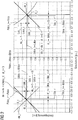
- FIG. 2 illustrates a diagram in which the normalized DC on the abscissa and the normalized DC voltage are shown on the ordinate. It is assumed that, in contrast to the representation of FIG. 1 only a rectifier is connected via a DC link with a working as an inverter VSC.
- the diagram shows the parameters and controlled variables of the rectifier in the left quadrant of the diagram and corresponding sizes of the inverter in the right quadrant.
- the measured direct current and the measuring direct voltage are plotted in measuring point X_r.
- the DC measurement voltage Udc_r is thus greater than the desired DC voltage Udco or Udco_r.
- a normalization to the setpoint DC current Idco_r is omitted in order to allow a nominal direct current of zero in the control.
- + di_r becomes minimal, ie zero. This results in the line shown on the left as a tangent to the dashed hyperbola, which represents the invariant setpoint power Pdco_r -Pdco.
- DC measurement current Idc_i and measurement DC voltage Udc_i are plotted at the operating point X_i.
- differential DC voltage du_i and differential DC current di_i are calculated, whereby the differential voltage du_i is again normalized to the nominal DC voltage Udco.
- du_i is greater than zero.
- setpoint direct currents Idco_i equal to 0 can be specified.
- the differential DC current di_i is less than zero for the desired power transmission.
- the control deviation de_i is formed from the sum of the differential DC voltage du_i and the differential direct current di_i.
- FIG. 3 schematically shows an embodiment of the method according to the invention for an HVDC system according to FIG. 1 , where the parameters and sizes according to FIG. 2 for a rectifier control 7_r1 of the rectifier station r_1 or for an inverter control 8_i1 of the inverter station i1 are used.
- the not figuratively illustrated rectifier regulations 7_rr and the inverter control 8_ii not shown are identical.
- each rectifier control receives a setpoint nominal power Pdco_r1 assigned to it.
- Pdco_r1 setpoint nominal power assigned to it.
- the inverter control 8_i1 wherein the respective associated desired DC power is transmitted from a central control center via communication links, not shown, for example, a simple radio link to the respective stations.
- the received nominal DC power Pdco_r1 or Pdco_i1 is in each case supplied to a divisor 9, at whose second input the nominal DC voltage Udco, which is the same for all stations, is applied.
- the desired DC power is also transmitted, for example, from a central station.
- the divisor 9 forms the quotient of the respective setpoint DC power Pdco and the setpoint DC voltage Udco while obtaining the setpoint DC current Idco_r1 or Idco_i1, wherein the respective setpoint DC current is supplied to a limiter 10, which sets the nominal DC current Idco_r1 or Idco_i1 to a minimum nominal direct current Imin_r1, Imin_i1 and a maximum nominal direct current Imax_r1, Imax_i1 limited.
- the setpoint direct current Idco_r1 or Idco_i1 is then fed to an adder 11, which respectively forms the difference between the setpoint direct current Idco_r1 or Id-co_i1 and the measured direct current Idc_r1 or Idco_i1.
- the differential DC current di_r1 obtained in this way is subsequently supplied to a further adder 11.
- the value at the second input said adder 11 is derived from the measurement voltage and the target voltage. For this purpose, in the case of the divisor 12, the quotient of the measured DC voltage Udc_r1 or Udc_i1 and of the desired DC voltage Udco is determined in each case.
- the differential DC voltage du_r1 with the absolute value of the nominal direct current
- * du_r1 is formed by means of a multiplier 24.
- the differential direct current di_r1 in the rectifier control 7_r1 becomes the product of du_r1 and
- the control deviation of the rectifier de_r1 is then fed to the controller 13 and finally to a module management system 14, which takes over the control of the power semiconductors of the respective VSCs here.
- VSCs are so-called multilevel VSCs, which, like all VSCs, consist of a bridge circuit of current valves.
- each flow control valve is formed from a series connection of bipolar submodules, each of which has an energy store and a circuit in parallel with the energy store Have power semiconductors, so that the voltage drop across the energy storage voltage or a zero voltage drops depending on the control of the power semiconductors at the respective submodule.
- the total voltage drop across the flow control valves adds up to the output voltages of the submodules and can thus be changed step by step.
- the output of the regulator 13 is applied to the input of the so-called module management system, the exact configuration thereof is not discussed here in the context of the invention, as this is not essential to the invention.
- the module management system controls the power semiconductors of the submodules to the output of the controller 13 accordingly.
- a pulse width modulator which is set up to control two-stage or three-stage Voltage Source Converter.
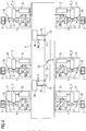
- FIG. 4 also shows an HVDC system to illustrate an embodiment of the method according to the invention.
- several rectifier stations r1, r2 ... rr and several inverter stations i1, i2 ... ii are connected to each other again via a DC voltage network 4 of any desired topology.
- Each rectifier station rr and each inverter station ii comprises, in addition to a rectifier control 7_rr or inverter control 8_ii, a protection unit 15 which is connected to the respective rectifier control 7_rr or inverter control 8_ii.
- the respective rectifier control 7_rr or inverter control 8_ii is further connected in each case with a protective device 16 of a circuit breaker 17, wherein the switch 17 between the AC voltage network 3 and the transformer 2 is arranged.
- a protective device 16 of a circuit breaker 17 wherein the switch 17 between the AC voltage network 3 and the transformer 2 is arranged.
- the protection trip takes place via the protection unit 15, which causes the respective control unit 7 to issue a trip command to the protective device 16.
- the protective device 16 opens the circuit breaker 17.
- DC voltage switches 19 are arranged in the DC voltage connections.
- a DC voltage protection unit 20 which is connected to the output of a DC voltage sensor 21 which provides DC values Idc_b1 and Idc_b2, which correspond to the DC current flowing through the respective switch 19.
- the DC voltage protection unit 20 is in turn connected to the protective device 16 of the DC voltage switch 19.
- the protection unit 15 now controls the respective control unit in such a way that it sets the respective nominal direct current Idco_r1, Idco_r2, Idco_rr or Idco_i1, Id_co_i2 and Idco_ii to zero over a zero-current duration, so that the respective measured direct current is regulated to zero.
- the DC current Idc_b1 or Idc_b2 flowing through the DC switches 19 also becomes equal to zero.
- the switch 19 can now be opened without power.
- the achievement of the switch-off time is also detected by the DC voltage protection unit 20 by time comparison. After maintaining a safety period which is smaller than a zero-current period, it comes to the currentless opening of the DC switch 19 and thus to disconnecting the DC section 18.
Landscapes
- Engineering & Computer Science (AREA)
- Power Engineering (AREA)
- Inverter Devices (AREA)
- Rectifiers (AREA)
Claims (16)
- Procédé de régulation d'au moins deux convertisseurs (1), qui peuvent être réglés en redresseur ou en onduleur et qui sont reliés entre eux par une liaison (4) en tension continue, dans le domaine du transport d'énergie et/ou de la répartition d'énergie, dans lequel- on mesure, sur chaque convertisseur (1), respectivement, une tension (Udc_r1...Udc_rr; Udc_i1...Udc_ii) continue de mesure et, respectivement, un courant (Idc_r1...Idc_rr; Idc_il...Idc_ii) continu de mesure et on les transmet à une régulation (7_rr) de redresseur pour la régulation du redresseur respectif ou à une régulation (8_ii) d'onduleur pour la régulation de l'onduleur associé respectivement,- dans lequel chaque régulation (7_rr) de redresseur et chaque régulation (8_ii) d'onduleur forment respectivement la différence entre une tension (Udco) continue de consigne donnée à l'avance et la tension (Udc_r1...Udc_rr; Udc_i1...Udc_ii) continue de mesure reçue respectivement, en obtenant une tension (du) continue de différence et en outre la différence entre un courant (Idc_r1...Idco_rr, Idco_i1...Idco_ii) continu de consigne et le courant (Idc_r1...Idc_rr; Idc_i1...Idc_ii) continu de mesure reçu respectivement, en obtenant un courant (di) continu de différence, le courant continu de mesure, la tension continue de mesure, le courant continu de consigne et la tension continue de consigne étant normés, et- chaque convertisseur est un convertisseur (1) automatique à semi-conducteur de puissance pouvant être mis à l'état bloqué,caractérisé en ce que- la régulation (7_rr) de redresseur règle le convertisseur (1) associé respectivement, de manière à ce que la somme du produit de la tension (du) continue de différence par la valeur absolue du courant (Idco_r|) continu de consigne prévu sur le redresseur associé, respectivement, du courant (du) continu de différence soit minimum (du*|Idco_r|+di→Min) et
la régulation (8_ii) d'onduleur régule le convertisseur (1) associé, respectivement, de manière à ce que la somme entre la tension (du) continue de différence et le courant (di) continu de différence soit minimum (du+di→Min). - Procédé suivant la revendication 1
caractérisé en ce que
la tension (Udco) continue de consigne de chaque régulation de redresseur et la tension (Udco) continue de consigne de chaque régulation d'onduleur sont les mêmes. - Procédé suivant la revendication 1 ou 2,
caractérisé en ce que
les convertisseurs (1) sont installés en étant éloignés l'un de l'autre d'au moins 1 km. - Procédé suivant l'une des revendications précédentes, caractérisé en ce que
l'on norme la tension (Udc_rr) continue de mesure et la tension (Udco) continue de consigne sur la tension (Udco) continue de consigne. - Procédé suivant l'une des revendications précédentes, caractérisé en ce
qu'il est prévu deux convertisseurs (1), dont l'un fonctionne en redresseur et l'autre en onduleur, un circuit (4) intermédiaire de tension continue s'étendant entre le redresseur et l'onduleur. - Procédé suivant l'une des revendications 1 à 4,
caractérisé en ce
qu'il est prévu au moins trois convertisseurs (1), entre lesquels s'étend un réseau (4) de tension continue. - Procédé suivant la revendication 6,
caractérisé en ce que,
pour chaque régulation (7_rr) de redresseur et pour chaque régulation (8_ii) d'onduleur, on fixe, respectivement, une puissance (Pdco_r1...Pdco_rr) continue de consigne de redresseur et une puissance (Pdco_i1...Pdco_ii) de consigne d'onduleur, la somme de toutes les puissances de consigne de redresseur et de toutes les puissances (∑ Pco_rr+∑ Pdco_ii) continues de consigne d'onduleur étant égales à zéro. - Procédé suivant la revendication 7,
caractérisé en ce que
l'on détermine, sur chaque convertisseur, le courant (Idco_rr; Idco_ii) continu de consigne associé, respectivement, au convertisseur (1) à partir de la puissance (Pdco_rr; Pdco_ii) continue de consigne associée et de la tension (Idco) continue de consigne commune à tous. - Procédé suivant l'une des revendications précédentes, caractérisé en ce que
la régulation de chaque redresseur et de chaque onduleur s'effectue sur toute la plage de travail du redresseur ou de l'onduleur, à la fois sur la base du courant (di_r1...di_rr) continu de différence de redresseur associé, respectivement, et sur la base de la tension (du_r1...du_rr) continue de différence de redresseur ou sur la base du courant (di_r1...di_rr) continu de différence d'onduleur associé, respectivement, et sur la base de la tension (du_i1...du_ii) continue de différence d'onduleur associé. - Procédé suivant l'une des revendications précédentes, caractérisé en ce que
l'on mesure sur chaque convertisseur (1) respectivement une tension (Udc_r1...Udc_rr; Udc_i1...Udc_ii) continue de mesure et respectivement un courant (Idc_r1...Idc_rr; Idc_i1...Idc_ii) continu de mesure et on les transmet à une régulation (7_rr) de redresseur ou à une régulation (8_ii) d'onduleur. - Procédé suivant la revendication 10,
caractérisé en ce que
l'on régule un certain nombre de convertisseurs (1), de manière à ce qu'un courant (Idc_b1;Idc_bd) continu, passant dans un sectionneur monté dans la liaison (4) de tension continue, soit égal à zéro. - Procédé suivant la revendication 10 ou 11,
caractérisé en ce qu'
au moins un convertisseur (1) régule à zéro le courant (Idc_rr;Idc_ii) continu de mesure détecté sur lui, respectivement, et ensuite on ouvre au moins un sectionneur (19) monté dans la liaison (4) de tension continue. - Procédé suivant l'une des revendications 11 ou 12, caractérisé en ce que
l'on fixe un instant (taus) de déconnexion et on le transmet aux régulations concernées, lesdites régulations régulant à zéro, lorsque l'instant (taus) de déconnexion est atteint, le courant (Idc_rr;Idc_ii) continu de mesure qui lui est associé. - Procédé suivant l'une des revendications 11 à 13,
caractérisé en ce que
l'on régule à zéro le courant (Idc_rr;Idc_ii) continu de mesure par chaque convertisseur (1) concerné pendant une durée de courant zéro et on effectue ensuite le procédé de régulation habituel. - Procédé suivant l'une des revendications 11 à 14,
caractérisé en ce que,
par l'ouverture du sectionneur (19), on sépare l'un des convertisseurs (1) de la liaison (4) de tension continue. - Procédé suivant l'une des revendications 11 à 15,
caractérisé en ce que,
par la fermeture du sectionneur (19), on sépare un tronçon (18) de la liaison (4) de tension continue sélectivement de la liaison (4) de tension continue.
Applications Claiming Priority (1)
| Application Number | Priority Date | Filing Date | Title |
|---|---|---|---|
| PCT/EP2008/005211 WO2009152840A1 (fr) | 2008-06-17 | 2008-06-17 | Procédé de réglage pour une installation de transmission de courant continu haute tension présentant un circuit intermédiaire à courant continu et des convertisseurs automatiques |
Publications (2)
| Publication Number | Publication Date |
|---|---|
| EP2289145A1 EP2289145A1 (fr) | 2011-03-02 |
| EP2289145B1 true EP2289145B1 (fr) | 2018-12-26 |
Family
ID=40299209
Family Applications (1)
| Application Number | Title | Priority Date | Filing Date |
|---|---|---|---|
| EP08773688.0A Active EP2289145B1 (fr) | 2008-06-17 | 2008-06-17 | Procédé de réglage pour une installation de transmission de courant continu haute tension présentant un circuit intermédiaire à courant continu et des convertisseurs automatiques |
Country Status (5)
| Country | Link |
|---|---|
| US (1) | US8351233B2 (fr) |
| EP (1) | EP2289145B1 (fr) |
| CN (1) | CN102067406B (fr) |
| BR (1) | BRPI0822822B8 (fr) |
| WO (1) | WO2009152840A1 (fr) |
Families Citing this family (14)
| Publication number | Priority date | Publication date | Assignee | Title |
|---|---|---|---|---|
| WO2012000549A1 (fr) * | 2010-06-30 | 2012-01-05 | Abb Research Ltd | Procédé et dispositif de commande pour commander un flux de puissance dans un réseau de transmission de puissance continue |
| FR2972085B1 (fr) * | 2011-02-25 | 2015-01-16 | Valeo Sys Controle Moteur Sas | Dispositif de conversion d'energie et procede de repartition associe |
| EP2495864B1 (fr) | 2011-03-02 | 2018-08-08 | GE Energy Power Conversion Technology Limited | Agencement de contrôle et procédé de régulation du courant de sortie d'un convertisseur de puissance de source cc connecté à un système cc multi-source |
| CN102545200A (zh) * | 2011-12-13 | 2012-07-04 | 河海大学 | 基于电压源换流器的多端直流配电网系统 |
| EP2941780B1 (fr) * | 2013-02-22 | 2018-03-28 | Siemens Aktiengesellschaft | Méthode pour couper un courant d'emploi |
| CN103296692A (zh) * | 2013-06-21 | 2013-09-11 | 国家电网公司 | 一种柔性直流输电系统换流站投入的控制设备及方法 |
| EP2897245B1 (fr) * | 2014-01-17 | 2017-07-26 | General Electric Technology GmbH | Réseau électrique à courant continu multi-terminaux |
| WO2016034233A1 (fr) * | 2014-09-04 | 2016-03-10 | Siemens Aktiengesellschaft | Procédé de contrôle d'un élément semi-conducteur haute puissance |
| CN104600738B (zh) * | 2015-01-21 | 2017-02-22 | 南京南瑞继保电气有限公司 | 一种高压直流输电串联阀组控制装置 |
| MD987Z (ro) * | 2015-04-02 | 2016-07-31 | ИНСТИТУТ ЭЛЕКТРОННОЙ ИНЖЕНЕРИИ И НАНОТЕХНОЛОГИЙ "D. Ghitu" АНМ | Sistem distribuit de alimentare cu energie electrică |
| US10116229B1 (en) * | 2017-09-19 | 2018-10-30 | King Saud University | Multilevel cascade hexagonal voltage source converter with isolated DC sources |
| CN108009341A (zh) * | 2017-11-28 | 2018-05-08 | 中国西电电气股份有限公司 | 一种换流阀饱和电抗器主电感饱和特性等效电路 |
| FI129353B (en) * | 2020-01-09 | 2021-12-31 | Lappeenrannan Lahden Teknillinen Yliopisto Lut | A system and method for estimating the electrical properties of an electrolyzer |
| CN113343456A (zh) * | 2021-05-31 | 2021-09-03 | 南方电网科学研究院有限责任公司 | Hvdc系统高精度闭环动态相量仿真计算、验证方法及装置 |
Family Cites Families (9)
| Publication number | Priority date | Publication date | Assignee | Title |
|---|---|---|---|---|
| US4443747A (en) * | 1982-04-01 | 1984-04-17 | General Electric Company | Transitioning between multiple modes of inverter control in a load commutated inverter motor drive |
| JP2507387B2 (ja) * | 1987-02-13 | 1996-06-12 | 株式会社東芝 | 電力変換装置 |
| WO1992015148A1 (fr) * | 1991-02-22 | 1992-09-03 | U.S. Windpower, Inc. | Unite de commande de moteur a quatre cadrans |
| JP3311214B2 (ja) * | 1995-09-05 | 2002-08-05 | 東京電力株式会社 | 電力変換装置の制御装置 |
| DE19544777C1 (de) * | 1995-11-30 | 1996-12-05 | Siemens Ag | Verfahren und Vorrichtung zur Regelung von Stromrichterstationen eines HGÜ-Mehrpunktnetzes |
| DE50110556D1 (de) * | 2000-09-13 | 2006-09-07 | Abb Research Ltd | Steuer- und regelverfahren für einen dreipunkt-stromrichter mit aktiven klemmschaltern sowie vorrichtung hierzu |
| EP1922803B1 (fr) * | 2005-09-09 | 2018-02-21 | Siemens Aktiengesellschaft | Dispositif de transmission d'energie electrique |
| WO2007033619A1 (fr) * | 2005-09-22 | 2007-03-29 | Siemens Akitengesellschaft | Procede de reglage pour une transmission de courant continu a l'aide de plusieurs convertisseurs de courant |
| DE102008007658A1 (de) * | 2008-02-06 | 2009-08-13 | Siemens Aktiengesellschaft | Statischer Umformer |
-
2008
- 2008-06-17 CN CN2008801299047A patent/CN102067406B/zh not_active Expired - Fee Related
- 2008-06-17 BR BRPI0822822A patent/BRPI0822822B8/pt active IP Right Grant
- 2008-06-17 WO PCT/EP2008/005211 patent/WO2009152840A1/fr not_active Ceased
- 2008-06-17 EP EP08773688.0A patent/EP2289145B1/fr active Active
- 2008-06-17 US US12/999,900 patent/US8351233B2/en active Active
Non-Patent Citations (1)
| Title |
|---|
| None * |
Also Published As
| Publication number | Publication date |
|---|---|
| BRPI0822822A2 (pt) | 2020-12-15 |
| US20110205771A1 (en) | 2011-08-25 |
| US8351233B2 (en) | 2013-01-08 |
| BRPI0822822B1 (pt) | 2021-08-17 |
| EP2289145A1 (fr) | 2011-03-02 |
| WO2009152840A1 (fr) | 2009-12-23 |
| CN102067406A (zh) | 2011-05-18 |
| CN102067406B (zh) | 2013-07-31 |
| BRPI0822822B8 (pt) | 2023-04-25 |
Similar Documents
| Publication | Publication Date | Title |
|---|---|---|
| EP2289145B1 (fr) | Procédé de réglage pour une installation de transmission de courant continu haute tension présentant un circuit intermédiaire à courant continu et des convertisseurs automatiques | |
| EP3280052B1 (fr) | Procede et dispositif de commande d'un circuit semi-conducteur de puissance commande par tension | |
| DE3225285C2 (de) | Verfahren zum Betrieb einer Hochspannungs-Gleichstrom-Übertragungsanlage mit beliebig vielen Umformerstationen | |
| EP3072143B1 (fr) | Dispositif de commutation d'un courant continu | |
| EP2614573B1 (fr) | Procédé de stabilisation d'un réseau d'alimentation électrique | |
| DE69817427T2 (de) | Anlage für elektrische Leistungsübertragung | |
| EP2926455B1 (fr) | Dispositif d'interruption de courants continus dans des branches de dérivation d'un noeud de réseau de tension continue | |
| EP3895313B1 (fr) | Dispositif de commutation destiné à séparer un chemin de courant | |
| EP2947766A1 (fr) | Alimentation électrique pour une charge non linéaire dotée de convertisseurs matriciels à plusieurs niveaux | |
| EP1927175B1 (fr) | Dispositif pour alimenter au moins une charge en énergie de manière redondante | |
| DE102019127198B4 (de) | Verfahren zum betrieb einer energieerzeugungsanlage und energieerzeugungsanlage mit dem verfahren | |
| EP3783783B1 (fr) | Agencement de régulation d'un flux de puissance dans un réseau à tension alternative et procédé de protection de l'agencement | |
| DE2127770C3 (de) | Gleichstrom-Leistungsschalter | |
| DE2127771A1 (de) | Gleichstrom Leistungsschalter | |
| EP2959492A2 (fr) | Changeur de prises en charge à éléments de commutation à semi-conducteurs et procédé pour faire fonctionner un changeur de prises en charge | |
| EP2624428A1 (fr) | Alimentation électrique C.C. modulaire avec des sorties indépendantes | |
| WO2014075740A1 (fr) | Dispositif de transformation | |
| DE102014119158A1 (de) | Selektives Parallellaufverfahren für Mess-/Steuergeräte | |
| WO2018054835A1 (fr) | Module solaire, installation photovoltaïque et procédé de limitation de tension | |
| EP2068416B2 (fr) | Précommande d'un convertisseur de source de tension | |
| EP3327911B1 (fr) | Procédé de commande d'un module de commutation faisant appel à des éléments de commutation de thyristor | |
| DE2710625C3 (de) | ,Kurzschlußschutzeinrichtung für ein Bordnetz großer Leistung | |
| EP2845214A1 (fr) | Dispositif destiné à la commutation dans un réseau de tension continue | |
| EP3392994B1 (fr) | Procédé de régulation de flux de puissance dans un réseau de tension continue | |
| EP2443728A1 (fr) | Alimentation en courant montée en parallèle avec un commutateur de puissance pour son circuit de commande |
Legal Events
| Date | Code | Title | Description |
|---|---|---|---|
| PUAI | Public reference made under article 153(3) epc to a published international application that has entered the european phase |
Free format text: ORIGINAL CODE: 0009012 |
|
| 17P | Request for examination filed |
Effective date: 20101116 |
|
| AK | Designated contracting states |
Kind code of ref document: A1 Designated state(s): AT BE BG CH CY CZ DE DK EE ES FI FR GB GR HR HU IE IS IT LI LT LU LV MC MT NL NO PL PT RO SE SI SK TR |
|
| AX | Request for extension of the european patent |
Extension state: AL BA MK RS |
|
| RIN1 | Information on inventor provided before grant (corrected) |
Inventor name: STRAUSS, JOHN-WILLIAM Inventor name: WITTSTOCK, CARSTEN Inventor name: DOMMASCHK, MIKE Inventor name: TU, QUOC-BUU Inventor name: EULER, INGO Inventor name: KARLECIK-MAIER, FRANZ Inventor name: DORN, JOERG Inventor name: LANG, JOERG Inventor name: VENJAKOB, OLIVER Inventor name: RITTIGER, JUERGEN Inventor name: BERNHARD, TOBIAS Inventor name: WUERFLINGER, KLAUS |
|
| DAX | Request for extension of the european patent (deleted) | ||
| RAP1 | Party data changed (applicant data changed or rights of an application transferred) |
Owner name: SIEMENS AKTIENGESELLSCHAFT |
|
| RAP1 | Party data changed (applicant data changed or rights of an application transferred) |
Owner name: SIEMENS AKTIENGESELLSCHAFT |
|
| GRAP | Despatch of communication of intention to grant a patent |
Free format text: ORIGINAL CODE: EPIDOSNIGR1 |
|
| STAA | Information on the status of an ep patent application or granted ep patent |
Free format text: STATUS: GRANT OF PATENT IS INTENDED |
|
| INTG | Intention to grant announced |
Effective date: 20180515 |
|
| GRAJ | Information related to disapproval of communication of intention to grant by the applicant or resumption of examination proceedings by the epo deleted |
Free format text: ORIGINAL CODE: EPIDOSDIGR1 |
|
| STAA | Information on the status of an ep patent application or granted ep patent |
Free format text: STATUS: REQUEST FOR EXAMINATION WAS MADE |
|
| INTC | Intention to grant announced (deleted) | ||
| GRAP | Despatch of communication of intention to grant a patent |
Free format text: ORIGINAL CODE: EPIDOSNIGR1 |
|
| STAA | Information on the status of an ep patent application or granted ep patent |
Free format text: STATUS: GRANT OF PATENT IS INTENDED |
|
| INTG | Intention to grant announced |
Effective date: 20180801 |
|
| GRAS | Grant fee paid |
Free format text: ORIGINAL CODE: EPIDOSNIGR3 |
|
| GRAA | (expected) grant |
Free format text: ORIGINAL CODE: 0009210 |
|
| STAA | Information on the status of an ep patent application or granted ep patent |
Free format text: STATUS: THE PATENT HAS BEEN GRANTED |
|
| AK | Designated contracting states |
Kind code of ref document: B1 Designated state(s): AT BE BG CH CY CZ DE DK EE ES FI FR GB GR HR HU IE IS IT LI LT LU LV MC MT NL NO PL PT RO SE SI SK TR |
|
| REG | Reference to a national code |
Ref country code: GB Ref legal event code: FG4D Free format text: NOT ENGLISH |
|
| REG | Reference to a national code |
Ref country code: CH Ref legal event code: EP |
|
| REG | Reference to a national code |
Ref country code: DE Ref legal event code: R096 Ref document number: 502008016535 Country of ref document: DE |
|
| REG | Reference to a national code |
Ref country code: AT Ref legal event code: REF Ref document number: 1082749 Country of ref document: AT Kind code of ref document: T Effective date: 20190115 |
|
| REG | Reference to a national code |
Ref country code: IE Ref legal event code: FG4D Free format text: LANGUAGE OF EP DOCUMENT: GERMAN |
|
| PG25 | Lapsed in a contracting state [announced via postgrant information from national office to epo] |
Ref country code: FI Free format text: LAPSE BECAUSE OF FAILURE TO SUBMIT A TRANSLATION OF THE DESCRIPTION OR TO PAY THE FEE WITHIN THE PRESCRIBED TIME-LIMIT Effective date: 20181226 Ref country code: LT Free format text: LAPSE BECAUSE OF FAILURE TO SUBMIT A TRANSLATION OF THE DESCRIPTION OR TO PAY THE FEE WITHIN THE PRESCRIBED TIME-LIMIT Effective date: 20181226 Ref country code: BG Free format text: LAPSE BECAUSE OF FAILURE TO SUBMIT A TRANSLATION OF THE DESCRIPTION OR TO PAY THE FEE WITHIN THE PRESCRIBED TIME-LIMIT Effective date: 20190326 Ref country code: NO Free format text: LAPSE BECAUSE OF FAILURE TO SUBMIT A TRANSLATION OF THE DESCRIPTION OR TO PAY THE FEE WITHIN THE PRESCRIBED TIME-LIMIT Effective date: 20190326 Ref country code: HR Free format text: LAPSE BECAUSE OF FAILURE TO SUBMIT A TRANSLATION OF THE DESCRIPTION OR TO PAY THE FEE WITHIN THE PRESCRIBED TIME-LIMIT Effective date: 20181226 Ref country code: LV Free format text: LAPSE BECAUSE OF FAILURE TO SUBMIT A TRANSLATION OF THE DESCRIPTION OR TO PAY THE FEE WITHIN THE PRESCRIBED TIME-LIMIT Effective date: 20181226 |
|
| REG | Reference to a national code |
Ref country code: NL Ref legal event code: MP Effective date: 20181226 |
|
| REG | Reference to a national code |
Ref country code: LT Ref legal event code: MG4D |
|
| PG25 | Lapsed in a contracting state [announced via postgrant information from national office to epo] |
Ref country code: SE Free format text: LAPSE BECAUSE OF FAILURE TO SUBMIT A TRANSLATION OF THE DESCRIPTION OR TO PAY THE FEE WITHIN THE PRESCRIBED TIME-LIMIT Effective date: 20181226 Ref country code: GR Free format text: LAPSE BECAUSE OF FAILURE TO SUBMIT A TRANSLATION OF THE DESCRIPTION OR TO PAY THE FEE WITHIN THE PRESCRIBED TIME-LIMIT Effective date: 20190327 |
|
| PG25 | Lapsed in a contracting state [announced via postgrant information from national office to epo] |
Ref country code: NL Free format text: LAPSE BECAUSE OF FAILURE TO SUBMIT A TRANSLATION OF THE DESCRIPTION OR TO PAY THE FEE WITHIN THE PRESCRIBED TIME-LIMIT Effective date: 20181226 |
|
| PG25 | Lapsed in a contracting state [announced via postgrant information from national office to epo] |
Ref country code: IT Free format text: LAPSE BECAUSE OF FAILURE TO SUBMIT A TRANSLATION OF THE DESCRIPTION OR TO PAY THE FEE WITHIN THE PRESCRIBED TIME-LIMIT Effective date: 20181226 Ref country code: PL Free format text: LAPSE BECAUSE OF FAILURE TO SUBMIT A TRANSLATION OF THE DESCRIPTION OR TO PAY THE FEE WITHIN THE PRESCRIBED TIME-LIMIT Effective date: 20181226 Ref country code: ES Free format text: LAPSE BECAUSE OF FAILURE TO SUBMIT A TRANSLATION OF THE DESCRIPTION OR TO PAY THE FEE WITHIN THE PRESCRIBED TIME-LIMIT Effective date: 20181226 Ref country code: CZ Free format text: LAPSE BECAUSE OF FAILURE TO SUBMIT A TRANSLATION OF THE DESCRIPTION OR TO PAY THE FEE WITHIN THE PRESCRIBED TIME-LIMIT Effective date: 20181226 Ref country code: PT Free format text: LAPSE BECAUSE OF FAILURE TO SUBMIT A TRANSLATION OF THE DESCRIPTION OR TO PAY THE FEE WITHIN THE PRESCRIBED TIME-LIMIT Effective date: 20190426 |
|
| PG25 | Lapsed in a contracting state [announced via postgrant information from national office to epo] |
Ref country code: EE Free format text: LAPSE BECAUSE OF FAILURE TO SUBMIT A TRANSLATION OF THE DESCRIPTION OR TO PAY THE FEE WITHIN THE PRESCRIBED TIME-LIMIT Effective date: 20181226 Ref country code: RO Free format text: LAPSE BECAUSE OF FAILURE TO SUBMIT A TRANSLATION OF THE DESCRIPTION OR TO PAY THE FEE WITHIN THE PRESCRIBED TIME-LIMIT Effective date: 20181226 Ref country code: IS Free format text: LAPSE BECAUSE OF FAILURE TO SUBMIT A TRANSLATION OF THE DESCRIPTION OR TO PAY THE FEE WITHIN THE PRESCRIBED TIME-LIMIT Effective date: 20190426 Ref country code: SK Free format text: LAPSE BECAUSE OF FAILURE TO SUBMIT A TRANSLATION OF THE DESCRIPTION OR TO PAY THE FEE WITHIN THE PRESCRIBED TIME-LIMIT Effective date: 20181226 |
|
| REG | Reference to a national code |
Ref country code: DE Ref legal event code: R097 Ref document number: 502008016535 Country of ref document: DE |
|
| PG25 | Lapsed in a contracting state [announced via postgrant information from national office to epo] |
Ref country code: DK Free format text: LAPSE BECAUSE OF FAILURE TO SUBMIT A TRANSLATION OF THE DESCRIPTION OR TO PAY THE FEE WITHIN THE PRESCRIBED TIME-LIMIT Effective date: 20181226 |
|
| PLBE | No opposition filed within time limit |
Free format text: ORIGINAL CODE: 0009261 |
|
| STAA | Information on the status of an ep patent application or granted ep patent |
Free format text: STATUS: NO OPPOSITION FILED WITHIN TIME LIMIT |
|
| 26N | No opposition filed |
Effective date: 20190927 |
|
| PG25 | Lapsed in a contracting state [announced via postgrant information from national office to epo] |
Ref country code: MC Free format text: LAPSE BECAUSE OF FAILURE TO SUBMIT A TRANSLATION OF THE DESCRIPTION OR TO PAY THE FEE WITHIN THE PRESCRIBED TIME-LIMIT Effective date: 20181226 |
|
| REG | Reference to a national code |
Ref country code: CH Ref legal event code: PL |
|
| PG25 | Lapsed in a contracting state [announced via postgrant information from national office to epo] |
Ref country code: SI Free format text: LAPSE BECAUSE OF FAILURE TO SUBMIT A TRANSLATION OF THE DESCRIPTION OR TO PAY THE FEE WITHIN THE PRESCRIBED TIME-LIMIT Effective date: 20181226 |
|
| REG | Reference to a national code |
Ref country code: BE Ref legal event code: MM Effective date: 20190630 |
|
| PG25 | Lapsed in a contracting state [announced via postgrant information from national office to epo] |
Ref country code: TR Free format text: LAPSE BECAUSE OF FAILURE TO SUBMIT A TRANSLATION OF THE DESCRIPTION OR TO PAY THE FEE WITHIN THE PRESCRIBED TIME-LIMIT Effective date: 20181226 |
|
| PG25 | Lapsed in a contracting state [announced via postgrant information from national office to epo] |
Ref country code: IE Free format text: LAPSE BECAUSE OF NON-PAYMENT OF DUE FEES Effective date: 20190617 |
|
| PG25 | Lapsed in a contracting state [announced via postgrant information from national office to epo] |
Ref country code: LI Free format text: LAPSE BECAUSE OF NON-PAYMENT OF DUE FEES Effective date: 20190630 Ref country code: BE Free format text: LAPSE BECAUSE OF NON-PAYMENT OF DUE FEES Effective date: 20190630 Ref country code: CH Free format text: LAPSE BECAUSE OF NON-PAYMENT OF DUE FEES Effective date: 20190630 Ref country code: LU Free format text: LAPSE BECAUSE OF NON-PAYMENT OF DUE FEES Effective date: 20190617 |
|
| REG | Reference to a national code |
Ref country code: AT Ref legal event code: MM01 Ref document number: 1082749 Country of ref document: AT Kind code of ref document: T Effective date: 20190617 |
|
| PGFP | Annual fee paid to national office [announced via postgrant information from national office to epo] |
Ref country code: GB Payment date: 20200708 Year of fee payment: 13 Ref country code: DE Payment date: 20200819 Year of fee payment: 13 |
|
| PG25 | Lapsed in a contracting state [announced via postgrant information from national office to epo] |
Ref country code: AT Free format text: LAPSE BECAUSE OF NON-PAYMENT OF DUE FEES Effective date: 20190617 |
|
| REG | Reference to a national code |
Ref country code: DE Ref legal event code: R081 Ref document number: 502008016535 Country of ref document: DE Owner name: SIEMENS ENERGY GLOBAL GMBH & CO. KG, DE Free format text: FORMER OWNER: SIEMENS AKTIENGESELLSCHAFT, 80333 MUENCHEN, DE |
|
| PG25 | Lapsed in a contracting state [announced via postgrant information from national office to epo] |
Ref country code: CY Free format text: LAPSE BECAUSE OF FAILURE TO SUBMIT A TRANSLATION OF THE DESCRIPTION OR TO PAY THE FEE WITHIN THE PRESCRIBED TIME-LIMIT Effective date: 20181226 |
|
| PG25 | Lapsed in a contracting state [announced via postgrant information from national office to epo] |
Ref country code: HU Free format text: LAPSE BECAUSE OF FAILURE TO SUBMIT A TRANSLATION OF THE DESCRIPTION OR TO PAY THE FEE WITHIN THE PRESCRIBED TIME-LIMIT; INVALID AB INITIO Effective date: 20080617 Ref country code: MT Free format text: LAPSE BECAUSE OF FAILURE TO SUBMIT A TRANSLATION OF THE DESCRIPTION OR TO PAY THE FEE WITHIN THE PRESCRIBED TIME-LIMIT Effective date: 20181226 |
|
| REG | Reference to a national code |
Ref country code: DE Ref legal event code: R119 Ref document number: 502008016535 Country of ref document: DE |
|
| GBPC | Gb: european patent ceased through non-payment of renewal fee |
Effective date: 20210617 |
|
| PG25 | Lapsed in a contracting state [announced via postgrant information from national office to epo] |
Ref country code: GB Free format text: LAPSE BECAUSE OF NON-PAYMENT OF DUE FEES Effective date: 20210617 Ref country code: DE Free format text: LAPSE BECAUSE OF NON-PAYMENT OF DUE FEES Effective date: 20220101 |
|
| PGFP | Annual fee paid to national office [announced via postgrant information from national office to epo] |
Ref country code: FR Payment date: 20250624 Year of fee payment: 18 |