EP2289355A1 - Confectionneuse automatique de cigarettes - Google Patents
Confectionneuse automatique de cigarettes Download PDFInfo
- Publication number
- EP2289355A1 EP2289355A1 EP09171445A EP09171445A EP2289355A1 EP 2289355 A1 EP2289355 A1 EP 2289355A1 EP 09171445 A EP09171445 A EP 09171445A EP 09171445 A EP09171445 A EP 09171445A EP 2289355 A1 EP2289355 A1 EP 2289355A1
- Authority
- EP
- European Patent Office
- Prior art keywords
- container
- rotary disc
- linkage
- cigarette maker
- automatic cigarette
- Prior art date
- Legal status (The legal status is an assumption and is not a legal conclusion. Google has not performed a legal analysis and makes no representation as to the accuracy of the status listed.)
- Withdrawn
Links
Images



Classifications
-
- A—HUMAN NECESSITIES
- A24—TOBACCO; CIGARS; CIGARETTES; SIMULATED SMOKING DEVICES; SMOKERS' REQUISITES
- A24C—MACHINES FOR MAKING CIGARS OR CIGARETTES
- A24C5/00—Making cigarettes; Making tipping materials for, or attaching filters or mouthpieces to, cigars or cigarettes
- A24C5/02—Cigarette-filling machines
Definitions
- the present invention relates to a cigarette maker, and more particularly, to an automatic cigarette maker that is capable of filling tobacco leaves into several cigarette papers continuously.
- a conventional cigarette maker is typically used for the purpose of massive production and includes continuous processing lines. Besides, shredded tobacco leaves are placed into a series of cigarette papers by means of injection method. After that, the cigarette papers filled with tobacco leaves are processed to produce commercial cigarettes.
- tobacco leaves should be cut up first and then rolled in cigarette papers or filled into cigarette paper bags. Accordingly, it not only takes a lot of time and work to make cigarettes, but it is also difficult to control the tightness of tobacco leaves in the cigarette paper bags and will result in the problem of uneven taste.
- An object of the present invention is to provide an automatic cigarette maker, where a rotary disc can be moved forward and backward relative to the front side of a container and rotated at a constant angle. Thereby, tobacco leaves can be filled continuously to make several cigarettes continuously.
- Another object of the present invention is to provide an automatic cigarette maker provided with a pressure regulator for adjusting the pressure exerted to cigarette papers.
- a pressure regulator for adjusting the pressure exerted to cigarette papers.
- the present invention provides an automatic cigarette maker comprising a case, a feeding module, a rotary disc, and a linkage arrangement.
- the case is provided therein with a container that has an opening at the top thereof and is used for holding tobacco leaves.
- the container has an outlet at the front side thereof.
- a tobacco supply duct is connected to the front side of the container and is in communication with the outlet.
- the feeding module is provided in the container for pushing tobacco leaves out of the tobacco supply duct.
- the rotary disc includes a seat and a plurality of tubes, where the tubes are arranged at the peripheries of the seat in a form of circular array and each tube is provided with a cigarette paper therein.
- the linkage arrangement is positioned within the case.
- One end of the linkage arrangement is connected with the rotary disc for moving the rotary disc forward or backward relative to the front side of the container and for rotating the rotary disc at a constant angle to move the tubes into the tobacco supply duct one after another. Consequently, the tobacco leaves can be filled into each cigarette paper.
- the linkage arrangement includes a plurality of pillars, a slide seat, and a linkage element.
- the pillars are arranged at the peripheries of the rotary disc in a form of circular array.
- the slide seat is positioned in the case.
- One side of the slide seat is provided with a tract for receiving and guiding any one pillar, so that the rotary disc is rotated at a constant angle whenever the rotary disc is moved forward and backward once.
- One end of the linkage element is connected with the rotary disc while another end thereof is connected with the driver for moving the rotary disc forward or backward relative to the outlet of the container.
- the case is further provided with a pressure regulator therein.
- the pressure regulator includes a pressure-regulating module and a pressing element.
- the pressing element is connected with the pressure-regulating module in a way of being relatively movable.
- Fig.1 is an exploded perspective view showing part of an automatic cigarette maker in an embodiment of the present invention.
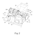
- Fig.2 is a perspective view showing part of the automatic cigarette maker in the embodiment of the present invention.
- Fig.3 is a perspective view showing a linkage arrangement and a rotary disc in the embodiment of the present invention.
- Fig.4 and 5 are schematic views showing the use of the embodiment of the present invention.
- the automatic cigarette maker 1 comprises a case 2, a feeding module 3, an agitating module 4, a pressure regulator 5, a rotary disc 6, and a linkage arrangement 7.
- the case 2 is generally in rectangular shape and includes a seat 21 and a cover 22 covering the seat 21. Space 23 is formed between the seat 21 and the cover 22.
- a container 24 having an opening 241 provided at the top thereof is fixed in the space 23 for holding tobacco leaves.
- the front side of the container 24 is provided with an outlet 242 and the outlet 242 is in communication with a tobacco supply duct 243 provided at the front side of the container 24 (as shown in Fig.2 ).
- the feeding module 3 includes a motor 31 and a propulsion shaft 32.
- the motor 31 is fixed at the rear side of the container 24.
- the propulsion shaft 32 is preferably a spiral shaft.
- the rear end of the propulsion shaft 32 is connected with the arbor of the motor 31.
- the propulsion shaft 32 is provided in the container 24.
- the agitating module 4 includes an agitator 41 and a motor 42.
- the agitator 41 is provided within the container 24 and the motor 42 is positioned outside the container 24.
- the agitator 41 includes a straight bar 411 and a plurality of short pillars 412, where the short pillars protrudes radially from the body of the straight bar 411.
- the front end of the straight bar 411 is positioned at the front plate of the container 24.
- the rear end of the straight bar 411 is connected with the arbor of the motor 42. Thereby, the tobacco leaves in the container 24 can be agitated by each short pillar 412 when the agitator 41 rotates.
- the pressure regulator 5 includes a pressure-regulating module 51 and a pressing element 52.
- the pressure-regulating module 51 includes a first fixing seat 53, a second fixing seat 54, an elastic element 55, and an adjusting element 56.
- the first fixing seat 23 is fixed at the L-shape plate of the seat 21;
- the second fixing seat 54 is a flat plate;
- the elastic element 55 is a U-shape spring;
- the adjusting element 56 is a tap bolt.
- the adjusting element 56 is screwed and positioned at the upright plate of the first fixing seat 53.
- Two ends of the elastic element 55 are respectively connected with one end of the adjusting element 56 and the pressing element 52.
- One end of the pressing element 52 is pivotally connected to the second fixing seat 54.
- the rotary disc 6 includes a seat 61 and a plurality of tubes 62.
- the seat 61 is provided with plural positioning plates 63 that are spaced from each other and a support plate 64.
- the peripheries of each positioning plate 63 are provided with positioning recesses 631 that are arranged in a form of circular array and used for positioning tubes 62 respectively.
- the support plate 64 is provided thereon with a plurality of positioning holes arranged in a form of circular array for positioning the rear ends of the tubes 62 respectively. Consequently, the tubes 62 are arranged in a form of circular array at the peripheries of the seat 61.
- the linkage arrangement 7 is positioned in the space 23 within the case 2.
- the linkage arrangement 7 includes a plurality of pillars 71, a slide seat 72, and a linkage element 73.
- the pillars 71 are arranged in a form of circular array and connected to the peripheries of the support plate 64 of the seat 61.
- One side of the slide seat 72 is provided with a tract 721.
- the tract 721 is used for receiving and guiding any one pillar 71 and includes a tract for moving forward 722 and a tract for moving backward 723 that is parallel to the tract for moving forward 722.
- the linkage element 73 includes a worm screw 731, a linkage plate 732, a linkage axis 733, a limit switch 734, a limit rod 735, and a limit element 736.
- the worm screw 731, the linkage axis 733, and the limit rod 735 are parallel to each other.
- the front end of the worm screw 731 is connected with a driver 74 and the driver 74 is a motor.
- the rear end of the worm screw 731 is screwed into a threaded hole 737 provided on the linkage plate 732, so that the linkage plate 732 can be moved forward or backward relative to the worm screw 731 when the worm screw 731 rotates.
- the rear end of the linkage axis 733 is connected to the linkage plate 732 while the front of the linkage plate 733 is connected with the seat 61 of the rotary disc 6.
- the limit switch 734 is fixed on the rear side of the linkage plate 732.
- the limit switch 734 and limit element 736 are respectively in electrical connection with the driver 74.
- the limit rod 735 is connected with the limit switch 734 and protrudes forward from the front side of the linkage plate 732.
- Figs.2 and 4 Please refer to Figs.2 and 4 .
- cylindrical cigarette papers 9 are first placed into the tubes 62 of the rotary disc 6.
- one tube 62 of the rotary disc 6 covers the tobacco supply duct 243.
- the agitator 41 in the container 24 is driven to rotate and agitate tobacco leaves.
- the propulsion shaft 32 of the feeding module 3 is also driven to rotate and push the tobacco leaves out of the tobacco supply duct 243 into the cigarette paper 9.
- the linkage plate 732, the linkage axis 733, and the rotary disc 6 can be moved forward synchronically via the relative motion of the linkage plate 732 and the worm screw 731. Consequently, one pillar 71 at the peripheries of the support plate 64 moves forward along the tract for moving forward 722 of the slide seat 72 and rotates.
- the driver 74 will inversely rotate to move the linkage plate 732, the linkage axis 733, and the rotary disc 6 backward. At this moment, the pillar 71 moves backward along the tract for moving backward 723 of the slide seat 72 and the rotary disc 6 continues to rotate so as to have another tube 62 cover the tobacco supply duct 243 for receiving tobacco leaves.
- the rotary disc 6 is rotated at a constant angle whenever the rotary disc 6 is moved relative to the container 24 forward and backward once. Thereby, the tubes 62 of the rotary disc 6 can cover the tobacco supply duct 243 one after another for receiving tobacco leaves therefrom.
- the present invention has following advantages:
- the tightness of the tobacco leaves in the cigarette papers can be effectively adjusted so as to meet individual requirements according to their preference.
- the present invention can provide an automatic cigarette maker that is capable of making several cigarettes continuously, ensuring the quality of the cigarette-making process, and meeting different requirements from individuals according to their preference. It is new and can be put into industrial use.
Landscapes
- Manufacturing Of Cigar And Cigarette Tobacco (AREA)
- Replacement Of Web Rolls (AREA)
Applications Claiming Priority (1)
| Application Number | Priority Date | Filing Date | Title |
|---|---|---|---|
| TW098125683A TW201103448A (en) | 2009-07-30 | 2009-07-30 | Automatic cigarette maker |
Publications (1)
| Publication Number | Publication Date |
|---|---|
| EP2289355A1 true EP2289355A1 (fr) | 2011-03-02 |
Family
ID=43426131
Family Applications (1)
| Application Number | Title | Priority Date | Filing Date |
|---|---|---|---|
| EP09171445A Withdrawn EP2289355A1 (fr) | 2009-07-30 | 2009-09-28 | Confectionneuse automatique de cigarettes |
Country Status (4)
| Country | Link |
|---|---|
| US (1) | US20110023894A1 (fr) |
| EP (1) | EP2289355A1 (fr) |
| JP (1) | JP2011030561A (fr) |
| TW (1) | TW201103448A (fr) |
Cited By (1)
| Publication number | Priority date | Publication date | Assignee | Title |
|---|---|---|---|---|
| CN108671829A (zh) * | 2018-03-14 | 2018-10-19 | 北方民族大学 | 一种多孔高分子吸收剂颗粒制备装置 |
Families Citing this family (8)
| Publication number | Priority date | Publication date | Assignee | Title |
|---|---|---|---|---|
| CA2647771A1 (fr) * | 2008-12-23 | 2010-06-23 | Philippe Thiry | Procede et dispositif de preparation de cigarettes |
| PL396132A1 (pl) * | 2011-08-30 | 2013-03-04 | Infoster Projekt Spólka Z Ograniczona Odpowiedzialnoscia | Urzadzenie do napelniania gilz papierosowych |
| USD769521S1 (en) * | 2014-05-15 | 2016-10-18 | Republic Tobacco L.P. | Horizontal cigarette-making machine |
| EP3427726B1 (fr) * | 2016-03-07 | 2023-05-03 | Osaka University | Feuille à libération prolongée de médicament pour traiter une lésion nerveuse |
| CN109222129B (zh) * | 2018-10-09 | 2020-07-14 | 中国农业大学 | 立式芦苇笋剥笋装置 |
| IL295099A (en) * | 2020-01-31 | 2022-09-01 | Rahamim Asaf | Cigarette preparation device |
| US20210267263A1 (en) * | 2020-02-28 | 2021-09-02 | Yamen HAIDARI | Automatic cigarette injection machine and an operation method of the same |
| CN113208159B (zh) * | 2021-04-29 | 2022-08-12 | 安徽亿能机械有限公司 | 基于卷烟机的自动包装机构 |
Citations (6)
| Publication number | Priority date | Publication date | Assignee | Title |
|---|---|---|---|---|
| DE180446C (fr) * | ||||
| FR352071A (fr) * | 1905-03-06 | 1905-08-02 | Leonard Lindeloef | Machine à bourrer les cigarettes |
| US2633133A (en) * | 1950-02-15 | 1953-03-31 | Claude S Hay | Cigarette making machine |
| EP0111713A1 (fr) * | 1982-12-22 | 1984-06-27 | HARTING ELEKTRONIK GmbH | Dispositif de remplissage de tubes à cigarettes |
| EP0746988A1 (fr) * | 1995-06-10 | 1996-12-11 | CHILINOV S.à.r.l. | Procédé et dispositif pour remplir des tubes à papier avec du tabac |
| EP1138214A2 (fr) * | 1998-03-23 | 2001-10-04 | British American Tobacco (Germany) GmbH | Appareil de confection personnelle de cigarettes et composants dudit appareil |
Family Cites Families (3)
| Publication number | Priority date | Publication date | Assignee | Title |
|---|---|---|---|---|
| US595474A (en) * | 1897-12-14 | hayden | ||
| GB391684A (en) * | 1932-03-08 | 1933-05-04 | Muller J C & Co | Improved apparatus for the manufacture of cigarettes with mouthpieces |
| US7905235B2 (en) * | 2008-05-22 | 2011-03-15 | Shargio Patel | Cigarette rolling machine |
-
2009
- 2009-07-30 TW TW098125683A patent/TW201103448A/zh unknown
- 2009-09-28 EP EP09171445A patent/EP2289355A1/fr not_active Withdrawn
- 2009-10-01 JP JP2009229694A patent/JP2011030561A/ja active Pending
- 2009-10-05 US US12/573,650 patent/US20110023894A1/en not_active Abandoned
Patent Citations (6)
| Publication number | Priority date | Publication date | Assignee | Title |
|---|---|---|---|---|
| DE180446C (fr) * | ||||
| FR352071A (fr) * | 1905-03-06 | 1905-08-02 | Leonard Lindeloef | Machine à bourrer les cigarettes |
| US2633133A (en) * | 1950-02-15 | 1953-03-31 | Claude S Hay | Cigarette making machine |
| EP0111713A1 (fr) * | 1982-12-22 | 1984-06-27 | HARTING ELEKTRONIK GmbH | Dispositif de remplissage de tubes à cigarettes |
| EP0746988A1 (fr) * | 1995-06-10 | 1996-12-11 | CHILINOV S.à.r.l. | Procédé et dispositif pour remplir des tubes à papier avec du tabac |
| EP1138214A2 (fr) * | 1998-03-23 | 2001-10-04 | British American Tobacco (Germany) GmbH | Appareil de confection personnelle de cigarettes et composants dudit appareil |
Cited By (2)
| Publication number | Priority date | Publication date | Assignee | Title |
|---|---|---|---|---|
| CN108671829A (zh) * | 2018-03-14 | 2018-10-19 | 北方民族大学 | 一种多孔高分子吸收剂颗粒制备装置 |
| CN108671829B (zh) * | 2018-03-14 | 2020-07-03 | 北方民族大学 | 一种多孔高分子吸收剂颗粒制备装置 |
Also Published As
| Publication number | Publication date |
|---|---|
| TW201103448A (en) | 2011-02-01 |
| JP2011030561A (ja) | 2011-02-17 |
| US20110023894A1 (en) | 2011-02-03 |
Similar Documents
| Publication | Publication Date | Title |
|---|---|---|
| EP2289355A1 (fr) | Confectionneuse automatique de cigarettes | |
| JP4875999B2 (ja) | 米飯成形装置 | |
| JP4279783B2 (ja) | 計量された分量のタバコ葉をタバコチューブに充填するための装置 | |
| JP2018108349A (ja) | ポルタフィルタ内に投入されたコーヒーを押圧するための装置 | |
| AU2008100097A4 (en) | Cigarette making device | |
| JP2018154431A (ja) | 粉体供給装置 | |
| US20090000695A1 (en) | Electric pencil sharpener | |
| CN111165529B (zh) | 一种全自动面条机 | |
| CN215794562U (zh) | 一种可调节的速溶性豆浆粉定量设备 | |
| JP2007111593A (ja) | 電動石臼 | |
| CN112520434B (zh) | 一种效率高的工业产品原料生产用下料机构 | |
| CN217049980U (zh) | 一种用于存放中药提取物的储料仓 | |
| CN110200294A (zh) | 一种坚果的破壳方法及可自动控制破壳压力的坚果破壳机 | |
| CN205129772U (zh) | 一种电动订书机 | |
| KR101477576B1 (ko) | 음료용 원재료 수용 캡슐로부터 음료를 추출하는 장치 | |
| JP2020058404A (ja) | コーヒーメーカー | |
| AU2010212368A1 (en) | Cigarette making device | |
| CN113116149A (zh) | 基于物联网的多级研磨智能咖啡机及控制方法 | |
| CN213056221U (zh) | 一种制袋机的涂胶机构 | |
| CN218132294U (zh) | 一种生产石灰石微粉的管磨机 | |
| CN222495556U (zh) | 一种便于调节大小的小氢片压片装置 | |
| CN220587250U (zh) | 一种多角度调节的投喂机 | |
| CN210340334U (zh) | 一种用于生产硫磺的制片机 | |
| CN221288151U (zh) | 一种按压式研磨器 | |
| CN223053814U (zh) | 一种茶叶加工用茶叶压扁机构 |
Legal Events
| Date | Code | Title | Description |
|---|---|---|---|
| PUAI | Public reference made under article 153(3) epc to a published international application that has entered the european phase |
Free format text: ORIGINAL CODE: 0009012 |
|
| AK | Designated contracting states |
Kind code of ref document: A1 Designated state(s): AT BE BG CH CY CZ DE DK EE ES FI FR GB GR HR HU IE IS IT LI LT LU LV MC MK MT NL NO PL PT RO SE SI SK SM TR |
|
| STAA | Information on the status of an ep patent application or granted ep patent |
Free format text: STATUS: THE APPLICATION IS DEEMED TO BE WITHDRAWN |
|
| 18D | Application deemed to be withdrawn |
Effective date: 20110903 |