EP2289367B1 - Dispositif à écran rétractable et inclinable pour tables - Google Patents
Dispositif à écran rétractable et inclinable pour tables Download PDFInfo
- Publication number
- EP2289367B1 EP2289367B1 EP09750201.7A EP09750201A EP2289367B1 EP 2289367 B1 EP2289367 B1 EP 2289367B1 EP 09750201 A EP09750201 A EP 09750201A EP 2289367 B1 EP2289367 B1 EP 2289367B1
- Authority
- EP
- European Patent Office
- Prior art keywords
- screen
- movement
- rod
- lid
- axle
- Prior art date
- Legal status (The legal status is an assumption and is not a legal conclusion. Google has not performed a legal analysis and makes no representation as to the accuracy of the status listed.)
- Active
Links
Images



Classifications
-
- A—HUMAN NECESSITIES
- A47—FURNITURE; DOMESTIC ARTICLES OR APPLIANCES; COFFEE MILLS; SPICE MILLS; SUCTION CLEANERS IN GENERAL
- A47B—TABLES; DESKS; OFFICE FURNITURE; CABINETS; DRAWERS; GENERAL DETAILS OF FURNITURE
- A47B21/00—Tables or desks for office equipment, e.g. typewriters, keyboards
- A47B21/007—Tables or desks for office equipment, e.g. typewriters, keyboards with under-desk displays, e.g. displays being viewable through a transparent working surface of the table or desk
- A47B21/0073—Tables or desks for office equipment, e.g. typewriters, keyboards with under-desk displays, e.g. displays being viewable through a transparent working surface of the table or desk liftable above the desk top
-
- A—HUMAN NECESSITIES
- A47—FURNITURE; DOMESTIC ARTICLES OR APPLIANCES; COFFEE MILLS; SPICE MILLS; SUCTION CLEANERS IN GENERAL
- A47B—TABLES; DESKS; OFFICE FURNITURE; CABINETS; DRAWERS; GENERAL DETAILS OF FURNITURE
- A47B81/00—Cabinets or racks specially adapted for other particular purposes, e.g. for storing guns or skis
- A47B81/06—Furniture aspects of radio, television, gramophone, or record cabinets
- A47B81/061—Furniture aspects of radio, television, gramophone, or record cabinets the device supports being adjustable
Definitions
- the present invention relates to a retractable tilted screen device for desks, which optimizes space utilization while being convenient to use for users.
- retractable screen devices for desks comprising means for guiding the screen between a vertical concealed position wherein the screen is housed below the surface of the table and a working position wherein the screen protrudes beyond said surface, which are designed to adapt the use of working desks and to protect the screens.
- these devices comprise a housing which houses the screen and the sliding mechanism of the screen between the two positions and is arranged under the desk.
- This housing has the disadvantage of occupying a space under the table which may be uncomfortable for the user whose leg-space is reduced.
- Another solution is to dispense with the tilt of the screen when being used, but the disadvantage is that the user's line of vision is not perpendicular to the plane of the screen and eye contact with others is reduced, with the discomfort this entails.
- these devices generally comprise a lid to close the opening, designed to keep the housing closed when the screen is hidden, especially to provide a desk without inconvenient holes in the surface when the screens are not being used and to avoid dust or any object entering when the screen is not in use.
- a retractable screen device that solves the problems described is needed, namely, that both in extreme positions and in positions taken when in movement, the screen should take up as little space as possible under the table to avoid invading the leg-space, while providing the desired inclination of the screen when in working position.
- the present invention also aims to provide a retractable screen device that has a lid which does not brush against the screen when it opens and is hidden when in working position.
- this invention provides a retractable screen device for desks, comprising a screen and means for guiding the screen between a substantially vertical concealed position whereby the screen is situated below the desk surface and a working position whereby the screen protrudes beyond the surface, and is characterized in that the guide means are configured to guide the screen in a movement that takes the screen from the concealed position to a working position which is inclined in relation to the desk surface, said movement being formed by a vertical translation until the screen protrudes noticeably beyond the surface followed by a rotation that takes the screen to the working position.
- This sequence of movements solves the technical problems, since it tilts the screen into its working position and on the other hand, allows the screen and its housing to be stored in a vertical position.
- the inclination corresponding to the working position is of about 20 degrees, optimum angle when the screen is arranged with its underside substantially at the level of the desk surface.
- the guide means comprise two horizontal axles joined in a fixed position to the screen, being located one below the other, a pair of straight upper axle guides that guide it according to a substantially vertical movement and at least another pair of lower axle guides with a straight part and a final upward stretch that guide it according to a movement with vertical and horizontal components in the final upward stretch, so the upward movement of the screen causes it to tilt.
- This configuration allows a twist at the end of the upward movement of the screen (or equivalently, at the beginning of the downward movement) and a translational movement during the rest of the trajectory.
- the pair of lower axle guides comprise a section near the surface of the desk which is tilted as regards to a lower section, which is substantially vertical, so that the screen tilts back, pivoting on the upper axle in a rotational movement, when the ends of the lower axle slide along the section of such guides which is near the surface.
- the screen can pivot with respect to a support according to such upper axle, so that this support transmits the efforts between the various parts, including the drive motor, and enables the easy removal of the screen for maintenance or replacement
- the lower axle guides comprise a last section substantially aligned with the lower section, so that the displacement at the end of the trajectory is substantially translational.
- the screen can still go an extra length without changing its inclination.
- This allows in particular simplifying the upward drive control, since no great accuracy is needed to deactivate the vertical displacement drive motor. Indeed, when reaching the working position, the screen takes speed and therefore has some kinetic energy. If the guide were to end at that point, either a motor control would be needed allowing reversing its rotational direction in a short time, or there would be an impact between the axle ends and the guide end. Therefore, the extension of the guide allows the screen to lose some kinetic energy by the action of gravity and also allows a less precise control system, that is, at a lower cost than that needed to stop the screen in a shorter trajectory.
- the device comprises a screen protection housing attached to the underside of the desk.
- the said support comprises four wheels that roll along such guides of the upper axle, so that these wheels and the support form a link between these guides and the upper axle guiding it according to a vertical movement.
- Cooperation between the four wheels and the upper axle guides ensure a smooth run of the upper axle in its vertical translational motion, and avoid ill linking conditioning.
- the device of the present invention comprises a lid closing said opening and means for moving the lid between a closed position and a retracted position whereby said lid is situated below the desk surface.
- the lid is substantially flush with the plane of the desk surface so that the desk has the whole of its working surface available when the screen is not in use, and furthermore has no parts in relief which could be unsightly.
- the means for moving the lid comprise a hinge axle between the lid and the desk, this axle being located close to one edge of the opening and below the level thereof, an articulated rod with an appendix joined to the lid so that movement of the rod induces a rotation of the lid, and linking means between the movement of the screen and the movement of the rod, so that the lid retracts shortly after the beginning of the ascent of the screen and closes just before the end of the descent of the screen.
- the linking means between the screen movement and the movement of the rod comprise a mounted slide along the rod and which rotates on an axle joined to the screen and provided with means to perform a drag force on the rod for an upward or downward stretch of the screen.
- the means for performing a drag force on the rod comprise a widening of the rod and a sliding mounted element on the slide driven by a spring toward the rod, the spring constants being determined so that when the element is at the level of the widening, the normal force exerted by the element on the rod causes an upward or downward frictional drag force, and when it is above the widening, it does not make contact with the rod.
- This system allows the slide, dragged by the screen itself, to activate the rod movement just enough to make the lid open and close.
- the device comprises means to stabilize the lid position in the closed position and in the retracted position.
- Such means which can be performed with a stable spring mechanism in the two positions, a set of magnets, or an imbalance between the lid and rod weights, guarantees the stability of the lid in each of the two resting positions, in the first two cases, or only the opening position in the third.
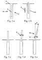
- the invention relates to a retractable screen 2 device 1 for desks 3, provided with means for guiding the screen between a significantly vertical concealed position A where the screen 2 is below the desk surface 3, preferably housed in a protective housing 13, and a working position B in which the screen 2 protrudes above the surface of the desk and is characterized in that the guide means are configured to guide the desk in a movement that takes the screen from a concealed position A to a working position B which is tilted as regards to the surface of the desk 3, preferably with an ⁇ angle of about 20 degrees, while said movement is formed by a vertical translation 4 until the screen 2 protrudes noticeably above the surface followed by a rotation 5, which takes the screen to the working position, thus enabling a comfortable viewing of the screen and maximum leg-space, as the pivoting with respect to the desk occurs with respect to an axle located on the underside of the screen, whereby it hardly takes up any space in front of the screen.
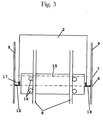
- the movement means of the screen include two horizontal axles 6 and 7 joined to the screen 2, one 6 being situated below the other 7, a pair of guides 8 of the upper axle 7 that guide it according to a substantially vertical movement and at least another pair of guides 9 of the lower axle 6 that guide it according to a movement with vertical and horizontal components, so that the upward movement of the screen 2 causes it to tilt.
- the movement with the vertical and horizontal components is accomplished in the present embodiment through the lower axle guides 9, which consist of a section 10 near the surface of the desk 3 tilted with respect to a lower section 11, which is substantially vertical so that the screen 2 is tilted backwards, rotationally 5 pivoting on the upper axle 7, when the ends 18 of the lower axle 6 slide down said section 10 of said guides 9 near the surface.
- the translational movement of the upper axle 7 is accomplished by mounting the latter on a support 15 having only one degree of free movement which is vertical. Therefore, the screen and support are articulated through the upper axle 7.
- the support 15 comprises four wheels 16 that roll along such guides 8 of the upper axle 7 so that these wheels and support are a link between the guides 8 and the upper axle 7 that guide it according to a vertical movement.
- the guides 9 have a last section 12 substantially aligned with the lower section 11, so that the displacement 13 is substantially translational at the end of the trajectory. Indeed, once the lower axle 6 has passed the inclined section, it begins to slide along this last stretch 12 which is parallel to section 11 along which the axle 6 continues to slide, so that the screen has a final movement that does not change the tilt. Therefore, the screen need not be immobilized when it has reached its tilted position, as it has a section without needing an accurate control, which would be expensive, ensuring the smooth operation of the device.
- the device of the invention comprises a control system, already known in itself, which includes an adapter card that controls the entries and exits to control the position of the screen using a microcontroller.
- These entries can be connected to position photocells and, preferably, the speed control in the upward movement involves a slow beginning, then changing to the normal speed, and when the lower axle enters the tilted section it goes back to a slow speed.
- the downward movement is equivalent but in reverse.
- the slow movements avoid sudden changes in the speed of the screen support assembly, particularly at the ends of the guides, where there is a greater risk of impact and therefore stress that may damage the device.
- the device of the invention may comprise an automatic shutdown system depending on the resistance detected in the upward or downward movements
- the device can be controlled by means of two buttons, one for going up and one for going down, mounted on the side of the opening, preferably on the right-hand side, and likewise each of them can be the stop button while the other has been pressed.
- Another alternative is to control it with a remote control or automation, such as AMX, Creston, or any other adapted to the device.
- the device 1 of the preferred embodiment is provided with a lid 20 to close the opening 19 of said desk 3 and means for moving between a closed position A and a retracted position C that allows the passage of the screen 2, and specifically in the device of the invention, the retracted position is located below the surface of the desk 3, as shown in Figure 5 . Therefore, to take it from the closed position A, in which, as shown in Figure 4 the lid 20 is flush with the plane of the surface of the desk 3, to the retracted position C, it does not need at any time to protrude beyond the plane of the desk 3, whereby the movements of the lid 20 are not impeded by objects that can be found inadvertently on the desk 3.
- the device 1 to move the lid 20 between the two positions A and C, the device 1 comprises a hinge axle 21 between the lid 20 and the desk 3 located close to an edge of the opening 19 and below the level thereof, a rod 22 articulated with an appendix 23 joined to the lid 5.
- these elements are arranged so that the movement 24 of the rod 22 induces a rotation 25 of the lid 20, and linking means between the movement 4 of the screen 2 and the movement 24 of the rod 22, so that the lid 20 withdraws soon after the screen 2 starts to rise and closes shortly before the end of the descent of the screen 2.
- This mechanism is very simple and reliable and prevents contact between the lid 20 and the screen 2.
- the linking means between the movement 4 of the screen 2 and the movement 24 of the rod 8 comprise a mounted slide 26 along the rod 22 and rotating on an axle 27 joined to the screen 2 and provided with means for dragging the rod 22 during an upward 32 or downward 31 trajectory of the screen 2.
- Axle 27 joined to the screen means that the movement of one implies that of the other according to a rigid body kinematics, but does not necessarily imply a direct binding of the joint axle 27 to the screen 2, yet rather preferably, both screen 2 and axle are fixed to a sturdy support responsible for driving the screen.
- the displacement of the lid 20 between its two extreme positions is achieved with a minimum displacement of rod 22 end, determined mainly by the length of said appendix 23.
- the means for performing a drag force on the rod 22 include a widening 28 of the rod 22 and a mounted sliding element 29 on the slide 26 driven by a spring 30 toward the rod 22, the spring 30 constants being determined such that when the element is at the height of the widening 28, the normal force exerted by the element 29 on the rod 22 causes an upward 32 or downward 31 frictional drag force, and when it is above the widening 28, it does not come into contact with the rod 22.
- Figure 6 shows a widening 28 whose section is offset with respect to the rod section 22 immediately above.
- This simple mechanism means that, in the extreme positions of the lid 20, i.e. the end of the appendix, the movement of the end of the rod 22 is prevented, and the friction force between the rod 22 and the element 29 and the larger section stretch, either upward 31 or downward 32, is strong enough to move the rod 22 in the opposite direction to that where it is blocked.
- Figure 6 shows the relative positions that may exist between the rod 22 and the slide 26. Specifically, when the slide 26 is in the lower position shown, whether going up or down, it drags the rod 22 upwards or downwards respectively, then opening or closing the lid 20 of the opening 19. When in the upper position, it is noted that the resting length of the spring 30 is determined such that the element 29 fails to make contact with the rod 22. Obviously, the widening 28 is very short, since a minimum run is needed to produce a rotation of the lid 20.
- the device of the invention comprises means to stabilize the position of the lid 20 in the closed position A and in the retracted position C, for example by a spring mechanism stable in both positions or a set of magnets, one in the lid 20 and another fixed to the desk 3 in the vicinity of the first when the lid 20 is open.
- Stability in the open position C can also be achieved with a mass difference between the lid 20 and the rod 22 causing an imbalance of moments that tend to leave the lid 20 in a retracted position C.
Landscapes
- Devices For Indicating Variable Information By Combining Individual Elements (AREA)
- Casings For Electric Apparatus (AREA)
- Accommodation For Nursing Or Treatment Tables (AREA)
- Tables And Desks Characterized By Structural Shape (AREA)
Claims (15)
- Dispositif (1) à écran incliné et rétractable (2) pour des bureaux (3), comprenant un écran (2) et des moyens pour guider l'écran entre une position dissimulée sensiblement verticale (A), dans laquelle l'écran (2) est situé en dessous de la surface du bureau (3), et une position de travail (B), dans laquelle l'écran (2) fait saillie au-delà de la surface, lesdits moyens de guidage étant configurés pour guider l'écran dans un déplacement qui prend l'écran à partir de la position dissimulée (A) jusqu'à une position de travail (B) qui est inclinée par rapport à la surface du bureau (3), ledit déplacement étant formé par une translation verticale (4) jusqu'à ce que l'écran (2) fasse saillie de façon significative au-delà de la surface, suivie par une rotation (5) qui prend l'écran jusqu'à la position de travail, caractérisé en ce que lesdits moyens comprennent deux axes horizontaux (6, 7) qui sont joints dans une position fixe à l'écran (2), un de ceux-ci étant situé (6) en dessous de l'autre (7), une paire de guides droits (8) de l'axe supérieur (7) qui guident celui-ci suivant un déplacement sensiblement vertical, et au moins une autre paire de guides (9) de l'axe inférieur (6) présentant une partie droite et une extension ascendante finale (10) qui guident celui-ci suivant un déplacement comprenant des composantes verticale et horizontale dans l'extension ascendante finale, de telle sorte que le déplacement vers le haut de l'écran (2) entraîne l'inclinaison de celui-ci.
- Dispositif (1) selon la revendication précédente, dans lequel l'inclinaison qui correspond à la position de travail (B) est d'approximativement 20 degrés.
- Dispositif (1) selon la revendication 1, dans lequel la paire de guides (9) de l'axe inférieur comprend une section (10) à proximité de la surface du bureau (3) qui est inclinée par rapport à une section inférieure (11), qui est sensiblement verticale, de telle sorte que l'écran (2) soit incliné vers l'arrière, pivotant sur l'axe supérieur (7) suivant une rotation (5), lorsque les extrémités de l'axe inférieur (6) coulissent le long de cette extension (10) desdits guides (9) à proximité de la surface.
- Dispositif (1) selon l'une quelconque des revendications précédentes, dans lequel lesdits guides d'axe inférieur (9) comprennent une dernière section (12) qui est alignée avec la section inférieure (11), de telle sorte que le déplacement (13) à la fin de la trajectoire soit sensiblement un mouvement de translation.
- Dispositif (1) selon la revendication 1, dans lequel il comprend un boîtier (14) pour protéger l'écran (2) qui est fixé au côté inférieur du bureau (3).
- Dispositif (1) selon la revendication 3, dans lequel l'écran (2) peut pivoter par rapport à un support (15) suivant l'axe supérieur (7).
- Dispositif (1) selon les revendications 1 et 6, dans lequel ledit support (15) comprend quatre roues dont l'axe est perpendiculaire au plan de déplacement général (16) et qui roulent le long desdits guides (8) de l'axe supérieur (7), ces roues et le support établissant de ce fait une liaison entre lesdits guides (8) et l'axe supérieur (7), guidant celui-ci suivant un déplacement vertical.
- Dispositif (1) selon l'une quelconque des revendications précédentes, comportant une ouverture (19) dans le bureau (3), un couvercle de fermeture (20) pour ladite ouverture (19) et des moyens pour déplacer le couvercle (20) entre une position fermée (A) et une position rétractée (C) qui permet le passage de l'écran (2), dans lequel la position rétractée (C) est située en dessous de la surface du bureau (3).
- Dispositif (1) selon la revendication 8, dans lequel, dans ladite position fermée (A), le couvercle (2) est sensiblement à fleur avec le plan de la surface du bureau (3).
- Dispositif (1) selon la revendication 8, dans lequel les moyens pour déplacer le couvercle comprennent un axe de charnière (21) entre le couvercle (20) et le bureau (3), ledit axe (21) étant situé à proximité d'un bord de l'ouverture (19) et en dessous du niveau de celle-ci, une tige (22) articulée avec un appendice (23) joint au couvercle (20) de telle sorte que le déplacement (24) de la tige (22) entraîne une rotation (25) du couvercle (20), et des moyens de liaison entre le déplacement (4) de l'écran (2) et le déplacement (24) de la tige (22), de telle sorte que le couvercle (20) se rétracte légèrement après que l'écran (2) ait commencé à se soulever, et se ferme légèrement avant la fin de la descente de l'écran (2).
- Dispositif (1) selon la revendication précédente, dans lequel les moyens de liaison entre le déplacement (4) de l'écran (2) et le déplacement (24) de la tige (22) comprennent un coulisseau (26) monté le long de la tige (22) et tournant autour d'un axe (27) joint à l'écran (2) et pourvu de moyens pour appliquer une force de traînée sur la tige (8) pendant un déplacement vers le haut (32) ou vers le bas (31) de l'écran (2).
- Dispositif (1) selon la revendication précédente, dans lequel lesdits moyens pour appliquer une force de traînée sur la tige (22) présentent un élargissement (28) de la tige (22) et un élément de coulissement (29) monté sur le coulisseau (26) entraîné par un ressort (30) en direction de la tige (22), les constantes du ressort (30) étant déterminées de telle sorte que lorsque l'élément se trouve à la hauteur de l'élargissement (28), la force normale exercée par l'élément (29) sur la tige (22) engendre une force de traînée de frottement vers le haut (32) ou vers le bas (31), et lorsqu'il se trouve au-dessus de l'élargissement, il ne réussisse pas à entrer en contact avec la tige.
- Dispositif (1) selon la revendication 8, dans lequel des moyens sont prévus pour stabiliser la position du couvercle (20) dans la position fermée (A) et dans la position rétractée (C).
- Dispositif (1) selon la revendication précédente, dans lequel lesdits moyens pour stabiliser la position comprennent un mécanisme de ressort stable à deux positions ou un ensemble d'aimants.
- Bureau équipé d'un dispositif selon l'une quelconque des revendications précédentes.
Applications Claiming Priority (3)
| Application Number | Priority Date | Filing Date | Title |
|---|---|---|---|
| ES200801078U ES1068016Y (es) | 2008-05-22 | 2008-05-22 | Dispositivo de pantalla retractil para mesas |
| ES200801079U ES1068395Y (es) | 2008-05-22 | 2008-05-22 | Dispositivo de pantalla retractil con inclinacion para mesas. |
| PCT/IB2009/051750 WO2009141744A1 (fr) | 2008-05-22 | 2009-04-29 | Dispositif à écran rétractable et inclinable pour tables |
Publications (3)
| Publication Number | Publication Date |
|---|---|
| EP2289367A1 EP2289367A1 (fr) | 2011-03-02 |
| EP2289367A4 EP2289367A4 (fr) | 2011-09-28 |
| EP2289367B1 true EP2289367B1 (fr) | 2014-10-29 |
Family
ID=41339817
Family Applications (1)
| Application Number | Title | Priority Date | Filing Date |
|---|---|---|---|
| EP09750201.7A Active EP2289367B1 (fr) | 2008-05-22 | 2009-04-29 | Dispositif à écran rétractable et inclinable pour tables |
Country Status (5)
| Country | Link |
|---|---|
| US (1) | US8291834B2 (fr) |
| EP (1) | EP2289367B1 (fr) |
| ES (1) | ES2528252T3 (fr) |
| RU (1) | RU2489071C2 (fr) |
| WO (1) | WO2009141744A1 (fr) |
Families Citing this family (14)
| Publication number | Priority date | Publication date | Assignee | Title |
|---|---|---|---|---|
| DE102008032362A1 (de) | 2008-07-10 | 2010-01-14 | Rosenthal Ag | Vorrichtung für das Anheben eines Flachbildschirms |
| CN102878389A (zh) * | 2011-07-11 | 2013-01-16 | 上海精仪达电子科技有限公司 | 大角度显示屏全自动升降器 |
| ES2400900B1 (es) | 2013-01-23 | 2014-02-27 | Soltec D'enginyeria I Projectes, S.L. | Dispositivo de pantalla retráctil con apertura de tapa autónoma de velocidad controlada |
| EP3310209A4 (fr) * | 2015-06-16 | 2019-03-27 | Amx Llc | Dispositif d'affichage rétractable |
| JP6605306B2 (ja) * | 2015-11-13 | 2019-11-13 | 日本電産サンキョー株式会社 | 複合駆動装置 |
| JP2017086700A (ja) * | 2015-11-13 | 2017-05-25 | 日本電産サンキョー株式会社 | 駆動装置 |
| JP6688173B2 (ja) * | 2016-06-27 | 2020-04-28 | 日本電産サンキョー株式会社 | チルト駆動装置 |
| JP6684666B2 (ja) * | 2016-06-27 | 2020-04-22 | 日本電産サンキョー株式会社 | 外力吸収装置および駆動装置 |
| ES2665544A1 (es) * | 2016-10-25 | 2018-04-26 | Albiral Display Solutions, S. L. | Conjunto de aparato ocultable y sistema que lo incluye |
| DE102016124303A1 (de) * | 2016-12-14 | 2018-06-14 | Ass-Einrichtungssysteme Gmbh | Verschlusssystem für ein Möbel |
| CN108872655B (zh) * | 2018-06-26 | 2020-11-10 | 浙江星皓科技股份有限公司 | 一种具有保护功能的电力仪表 |
| CN113525243B (zh) * | 2021-08-20 | 2023-06-02 | 上海延锋金桥汽车饰件系统有限公司 | 车辆内部部件和包括车辆内部部件的车辆 |
| US11910913B2 (en) | 2021-10-21 | 2024-02-27 | Crestron Electronics, Inc. | Pop-up display |
| CN115206210B (zh) * | 2022-07-19 | 2024-01-16 | 北京聚合梦想文化娱乐有限公司 | 一种展示柜投影展示装置及控制方法 |
Family Cites Families (23)
| Publication number | Priority date | Publication date | Assignee | Title |
|---|---|---|---|---|
| CH414547A (de) * | 1963-03-09 | 1966-06-15 | Kaufmann Josef | Aktenspeicher mit Ordnern |
| US4065194A (en) * | 1976-03-18 | 1977-12-27 | Mattia Armand D | Pulpit elevating and lowering system |
| US4766422A (en) * | 1986-05-23 | 1988-08-23 | Westinghouse Electric Corp. | Computer integrated desk |
| SU1655454A1 (ru) * | 1989-06-05 | 1991-06-15 | Центр Научно-Технического Творчества Молодежи "Политехника" | Стол-бар |
| US5847685A (en) * | 1992-08-19 | 1998-12-08 | Alpine Electronics, Inc. | Vehicle-mounted display mechanism |
| JP2570955B2 (ja) * | 1993-03-12 | 1997-01-16 | ヤマハ株式会社 | ディスプレイ昇降装置 |
| TW429987U (en) * | 2000-06-20 | 2001-04-11 | Chen Tz Yun | Lift screen |
| US20020101139A1 (en) * | 2001-01-30 | 2002-08-01 | Lee Tsai Ming | Elevating device for planer displayer |
| US6733094B1 (en) * | 2002-11-13 | 2004-05-11 | Chun-Chung Chang | Lifting device for LCD |
| US20040090154A1 (en) * | 2002-11-13 | 2004-05-13 | Chun-Chung Chang | Lift for LCD |
| US6902243B2 (en) * | 2003-02-25 | 2005-06-07 | Wieslaw Bober | Modular sub-cabinet for motion furniture |
| US7128003B2 (en) * | 2003-05-05 | 2006-10-31 | Marek Okninski | Lifting device for visual screens |
| US7207278B2 (en) * | 2003-07-03 | 2007-04-24 | Wright Line, Llc | Electrically-driven computer monitor lift and storage assembly |
| CN100433815C (zh) * | 2004-01-23 | 2008-11-12 | 巴兹尔·诺曼·弗里曼 | 支撑音/视频系统的装置及利用该装置的音/视频系统 |
| ES1057078Y (es) * | 2004-03-09 | 2004-10-01 | Avialec S L | Dispositivo de eyeccion y retraccion de una pantalla plana. |
| US20060238086A1 (en) * | 2005-04-20 | 2006-10-26 | Kuo-Wei Lai | Structure of a monitor support device with height adjusting function |
| ES1061088Y (es) * | 2005-07-08 | 2006-04-16 | Avialec S L | Dispositivo de elevacion y retraccion de una pantalla plana incluyendo una camara de captacion de imagen |
| US20070188056A1 (en) * | 2006-02-10 | 2007-08-16 | Shun-Sheng Chang | Artistic display rack |
| US7584705B2 (en) * | 2006-09-11 | 2009-09-08 | Chao-Lin Chen | Monitor rising and storing system |
| CN100520148C (zh) * | 2007-07-06 | 2009-07-29 | 深圳路美特科技有限公司 | 车载显示屏升降装置 |
| US7922267B2 (en) * | 2007-08-10 | 2011-04-12 | Krueger International, Inc. | Movable monitor and keyboard storage system for a worksurface |
| US20090102335A1 (en) * | 2007-10-19 | 2009-04-23 | David Hancock | Workstation |
| DE102008032362A1 (de) * | 2008-07-10 | 2010-01-14 | Rosenthal Ag | Vorrichtung für das Anheben eines Flachbildschirms |
-
2009
- 2009-04-29 US US12/994,005 patent/US8291834B2/en not_active Expired - Fee Related
- 2009-04-29 RU RU2010149944/12A patent/RU2489071C2/ru not_active IP Right Cessation
- 2009-04-29 WO PCT/IB2009/051750 patent/WO2009141744A1/fr not_active Ceased
- 2009-04-29 EP EP09750201.7A patent/EP2289367B1/fr active Active
- 2009-04-29 ES ES09750201.7T patent/ES2528252T3/es active Active
Also Published As
| Publication number | Publication date |
|---|---|
| WO2009141744A1 (fr) | 2009-11-26 |
| ES2528252T3 (es) | 2015-02-05 |
| EP2289367A1 (fr) | 2011-03-02 |
| EP2289367A4 (fr) | 2011-09-28 |
| US20110134522A1 (en) | 2011-06-09 |
| US8291834B2 (en) | 2012-10-23 |
| RU2010149944A (ru) | 2012-06-27 |
| RU2489071C2 (ru) | 2013-08-10 |
Similar Documents
| Publication | Publication Date | Title |
|---|---|---|
| US8291834B2 (en) | Tilting, retractable screen device for tables | |
| CN107864648A (zh) | 折叠桌 | |
| EP2810808B1 (fr) | Assemblage de soutien et retenue pour un dispositif électronique portable | |
| KR101237560B1 (ko) | 디스플레이 기기의 스탠드 | |
| KR101581881B1 (ko) | 모니터 자동수납 책상 | |
| CN108903264A (zh) | 超短翻降融合一体机 | |
| EP2116472A1 (fr) | Dispositif de confinement d'un sac à parapluie pliable | |
| CN108071289A (zh) | 一种集成优化的家具翻转结构 | |
| EP1514760A1 (fr) | Table escamotable pour compartiments de voitures de chemin de fer | |
| CN214803618U (zh) | 座椅底座及其座椅 | |
| CN112252873B (zh) | 一种利用阻尼力达到悬停的运动铰链 | |
| CN208931175U (zh) | 一种车载观景座椅 | |
| JP2015000209A (ja) | 昇降棚 | |
| CN114476077B (zh) | 一种航空旅客座椅电动升降餐桌 | |
| CN219742119U (zh) | 一种x型桌上单屏可调角度显示器支架 | |
| JP4602997B2 (ja) | 昇降収納ラックの収納装置 | |
| JP4443311B2 (ja) | 昇降収納ラックの収納装置 | |
| CN217610067U (zh) | 升降收纳装置 | |
| JP2000279237A (ja) | 可動式収納装置 | |
| CN201947572U (zh) | 一种电子装置 | |
| EP1574150A1 (fr) | Dispositif pour faire rentrer ou sortir un écran plat | |
| KR200348294Y1 (ko) | 모니터승강장치 | |
| JP2001120367A (ja) | 電動昇降装置 | |
| CN102824039B (zh) | 一种座椅 | |
| EP0315383A1 (fr) | Mécanisme d'actionnement pour porte basculante |
Legal Events
| Date | Code | Title | Description |
|---|---|---|---|
| PUAI | Public reference made under article 153(3) epc to a published international application that has entered the european phase |
Free format text: ORIGINAL CODE: 0009012 |
|
| 17P | Request for examination filed |
Effective date: 20101222 |
|
| AK | Designated contracting states |
Kind code of ref document: A1 Designated state(s): AT BE BG CH CY CZ DE DK EE ES FI FR GB GR HR HU IE IS IT LI LT LU LV MC MK MT NL NO PL PT RO SE SI SK TR |
|
| AX | Request for extension of the european patent |
Extension state: AL BA RS |
|
| RAX | Requested extension states of the european patent have changed |
Extension state: BA Payment date: 20101222 Extension state: RS Payment date: 20101222 |
|
| A4 | Supplementary search report drawn up and despatched |
Effective date: 20110830 |
|
| RIC1 | Information provided on ipc code assigned before grant |
Ipc: A47B 21/007 20060101AFI20110824BHEP Ipc: A47B 81/06 20060101ALI20110824BHEP Ipc: A47B 37/00 20060101ALI20110824BHEP |
|
| 17Q | First examination report despatched |
Effective date: 20121129 |
|
| GRAP | Despatch of communication of intention to grant a patent |
Free format text: ORIGINAL CODE: EPIDOSNIGR1 |
|
| INTG | Intention to grant announced |
Effective date: 20140516 |
|
| GRAS | Grant fee paid |
Free format text: ORIGINAL CODE: EPIDOSNIGR3 |
|
| GRAA | (expected) grant |
Free format text: ORIGINAL CODE: 0009210 |
|
| AK | Designated contracting states |
Kind code of ref document: B1 Designated state(s): AT BE BG CH CY CZ DE DK EE ES FI FR GB GR HR HU IE IS IT LI LT LU LV MC MK MT NL NO PL PT RO SE SI SK TR |
|
| AX | Request for extension of the european patent |
Extension state: BA RS |
|
| REG | Reference to a national code |
Ref country code: GB Ref legal event code: FG4D |
|
| REG | Reference to a national code |
Ref country code: CH Ref legal event code: EP |
|
| REG | Reference to a national code |
Ref country code: AT Ref legal event code: REF Ref document number: 693140 Country of ref document: AT Kind code of ref document: T Effective date: 20141115 |
|
| REG | Reference to a national code |
Ref country code: IE Ref legal event code: FG4D |
|
| REG | Reference to a national code |
Ref country code: DE Ref legal event code: R096 Ref document number: 602009027450 Country of ref document: DE Effective date: 20141211 |
|
| REG | Reference to a national code |
Ref country code: ES Ref legal event code: FG2A Ref document number: 2528252 Country of ref document: ES Kind code of ref document: T3 Effective date: 20150205 |
|
| REG | Reference to a national code |
Ref country code: AT Ref legal event code: MK05 Ref document number: 693140 Country of ref document: AT Kind code of ref document: T Effective date: 20141029 |
|
| REG | Reference to a national code |
Ref country code: NL Ref legal event code: VDEP Effective date: 20141029 |
|
| REG | Reference to a national code |
Ref country code: LT Ref legal event code: MG4D |
|
| PG25 | Lapsed in a contracting state [announced via postgrant information from national office to epo] |
Ref country code: LT Free format text: LAPSE BECAUSE OF FAILURE TO SUBMIT A TRANSLATION OF THE DESCRIPTION OR TO PAY THE FEE WITHIN THE PRESCRIBED TIME-LIMIT Effective date: 20141029 Ref country code: FI Free format text: LAPSE BECAUSE OF FAILURE TO SUBMIT A TRANSLATION OF THE DESCRIPTION OR TO PAY THE FEE WITHIN THE PRESCRIBED TIME-LIMIT Effective date: 20141029 Ref country code: NO Free format text: LAPSE BECAUSE OF FAILURE TO SUBMIT A TRANSLATION OF THE DESCRIPTION OR TO PAY THE FEE WITHIN THE PRESCRIBED TIME-LIMIT Effective date: 20150129 Ref country code: NL Free format text: LAPSE BECAUSE OF FAILURE TO SUBMIT A TRANSLATION OF THE DESCRIPTION OR TO PAY THE FEE WITHIN THE PRESCRIBED TIME-LIMIT Effective date: 20141029 Ref country code: PT Free format text: LAPSE BECAUSE OF FAILURE TO SUBMIT A TRANSLATION OF THE DESCRIPTION OR TO PAY THE FEE WITHIN THE PRESCRIBED TIME-LIMIT Effective date: 20150302 Ref country code: IS Free format text: LAPSE BECAUSE OF FAILURE TO SUBMIT A TRANSLATION OF THE DESCRIPTION OR TO PAY THE FEE WITHIN THE PRESCRIBED TIME-LIMIT Effective date: 20150228 |
|
| PG25 | Lapsed in a contracting state [announced via postgrant information from national office to epo] |
Ref country code: AT Free format text: LAPSE BECAUSE OF FAILURE TO SUBMIT A TRANSLATION OF THE DESCRIPTION OR TO PAY THE FEE WITHIN THE PRESCRIBED TIME-LIMIT Effective date: 20141029 Ref country code: CY Free format text: LAPSE BECAUSE OF FAILURE TO SUBMIT A TRANSLATION OF THE DESCRIPTION OR TO PAY THE FEE WITHIN THE PRESCRIBED TIME-LIMIT Effective date: 20141029 Ref country code: PL Free format text: LAPSE BECAUSE OF FAILURE TO SUBMIT A TRANSLATION OF THE DESCRIPTION OR TO PAY THE FEE WITHIN THE PRESCRIBED TIME-LIMIT Effective date: 20141029 Ref country code: SE Free format text: LAPSE BECAUSE OF FAILURE TO SUBMIT A TRANSLATION OF THE DESCRIPTION OR TO PAY THE FEE WITHIN THE PRESCRIBED TIME-LIMIT Effective date: 20141029 Ref country code: LV Free format text: LAPSE BECAUSE OF FAILURE TO SUBMIT A TRANSLATION OF THE DESCRIPTION OR TO PAY THE FEE WITHIN THE PRESCRIBED TIME-LIMIT Effective date: 20141029 Ref country code: GR Free format text: LAPSE BECAUSE OF FAILURE TO SUBMIT A TRANSLATION OF THE DESCRIPTION OR TO PAY THE FEE WITHIN THE PRESCRIBED TIME-LIMIT Effective date: 20150130 Ref country code: HR Free format text: LAPSE BECAUSE OF FAILURE TO SUBMIT A TRANSLATION OF THE DESCRIPTION OR TO PAY THE FEE WITHIN THE PRESCRIBED TIME-LIMIT Effective date: 20141029 |
|
| REG | Reference to a national code |
Ref country code: DE Ref legal event code: R097 Ref document number: 602009027450 Country of ref document: DE |
|
| PG25 | Lapsed in a contracting state [announced via postgrant information from national office to epo] |
Ref country code: CZ Free format text: LAPSE BECAUSE OF FAILURE TO SUBMIT A TRANSLATION OF THE DESCRIPTION OR TO PAY THE FEE WITHIN THE PRESCRIBED TIME-LIMIT Effective date: 20141029 Ref country code: RO Free format text: LAPSE BECAUSE OF FAILURE TO SUBMIT A TRANSLATION OF THE DESCRIPTION OR TO PAY THE FEE WITHIN THE PRESCRIBED TIME-LIMIT Effective date: 20141029 Ref country code: SK Free format text: LAPSE BECAUSE OF FAILURE TO SUBMIT A TRANSLATION OF THE DESCRIPTION OR TO PAY THE FEE WITHIN THE PRESCRIBED TIME-LIMIT Effective date: 20141029 Ref country code: DK Free format text: LAPSE BECAUSE OF FAILURE TO SUBMIT A TRANSLATION OF THE DESCRIPTION OR TO PAY THE FEE WITHIN THE PRESCRIBED TIME-LIMIT Effective date: 20141029 Ref country code: EE Free format text: LAPSE BECAUSE OF FAILURE TO SUBMIT A TRANSLATION OF THE DESCRIPTION OR TO PAY THE FEE WITHIN THE PRESCRIBED TIME-LIMIT Effective date: 20141029 |
|
| PLBE | No opposition filed within time limit |
Free format text: ORIGINAL CODE: 0009261 |
|
| STAA | Information on the status of an ep patent application or granted ep patent |
Free format text: STATUS: NO OPPOSITION FILED WITHIN TIME LIMIT |
|
| 26N | No opposition filed |
Effective date: 20150730 |
|
| PG25 | Lapsed in a contracting state [announced via postgrant information from national office to epo] |
Ref country code: LU Free format text: LAPSE BECAUSE OF FAILURE TO SUBMIT A TRANSLATION OF THE DESCRIPTION OR TO PAY THE FEE WITHIN THE PRESCRIBED TIME-LIMIT Effective date: 20150429 Ref country code: MC Free format text: LAPSE BECAUSE OF FAILURE TO SUBMIT A TRANSLATION OF THE DESCRIPTION OR TO PAY THE FEE WITHIN THE PRESCRIBED TIME-LIMIT Effective date: 20141029 |
|
| REG | Reference to a national code |
Ref country code: CH Ref legal event code: PL |
|
| REG | Reference to a national code |
Ref country code: IE Ref legal event code: MM4A |
|
| PG25 | Lapsed in a contracting state [announced via postgrant information from national office to epo] |
Ref country code: LI Free format text: LAPSE BECAUSE OF NON-PAYMENT OF DUE FEES Effective date: 20150430 Ref country code: CH Free format text: LAPSE BECAUSE OF NON-PAYMENT OF DUE FEES Effective date: 20150430 |
|
| PG25 | Lapsed in a contracting state [announced via postgrant information from national office to epo] |
Ref country code: SI Free format text: LAPSE BECAUSE OF FAILURE TO SUBMIT A TRANSLATION OF THE DESCRIPTION OR TO PAY THE FEE WITHIN THE PRESCRIBED TIME-LIMIT Effective date: 20141029 |
|
| REG | Reference to a national code |
Ref country code: FR Ref legal event code: PLFP Year of fee payment: 8 |
|
| PG25 | Lapsed in a contracting state [announced via postgrant information from national office to epo] |
Ref country code: IE Free format text: LAPSE BECAUSE OF NON-PAYMENT OF DUE FEES Effective date: 20150429 |
|
| PG25 | Lapsed in a contracting state [announced via postgrant information from national office to epo] |
Ref country code: MT Free format text: LAPSE BECAUSE OF FAILURE TO SUBMIT A TRANSLATION OF THE DESCRIPTION OR TO PAY THE FEE WITHIN THE PRESCRIBED TIME-LIMIT Effective date: 20141029 |
|
| REG | Reference to a national code |
Ref country code: FR Ref legal event code: PLFP Year of fee payment: 9 |
|
| PG25 | Lapsed in a contracting state [announced via postgrant information from national office to epo] |
Ref country code: BG Free format text: LAPSE BECAUSE OF FAILURE TO SUBMIT A TRANSLATION OF THE DESCRIPTION OR TO PAY THE FEE WITHIN THE PRESCRIBED TIME-LIMIT Effective date: 20141029 Ref country code: HU Free format text: LAPSE BECAUSE OF FAILURE TO SUBMIT A TRANSLATION OF THE DESCRIPTION OR TO PAY THE FEE WITHIN THE PRESCRIBED TIME-LIMIT; INVALID AB INITIO Effective date: 20090429 |
|
| PG25 | Lapsed in a contracting state [announced via postgrant information from national office to epo] |
Ref country code: TR Free format text: LAPSE BECAUSE OF FAILURE TO SUBMIT A TRANSLATION OF THE DESCRIPTION OR TO PAY THE FEE WITHIN THE PRESCRIBED TIME-LIMIT Effective date: 20141029 |
|
| PG25 | Lapsed in a contracting state [announced via postgrant information from national office to epo] |
Ref country code: BE Free format text: LAPSE BECAUSE OF FAILURE TO SUBMIT A TRANSLATION OF THE DESCRIPTION OR TO PAY THE FEE WITHIN THE PRESCRIBED TIME-LIMIT Effective date: 20141029 |
|
| REG | Reference to a national code |
Ref country code: FR Ref legal event code: PLFP Year of fee payment: 10 |
|
| PG25 | Lapsed in a contracting state [announced via postgrant information from national office to epo] |
Ref country code: MK Free format text: LAPSE BECAUSE OF FAILURE TO SUBMIT A TRANSLATION OF THE DESCRIPTION OR TO PAY THE FEE WITHIN THE PRESCRIBED TIME-LIMIT Effective date: 20141029 |
|
| PGFP | Annual fee paid to national office [announced via postgrant information from national office to epo] |
Ref country code: IT Payment date: 20180522 Year of fee payment: 10 Ref country code: FR Payment date: 20180511 Year of fee payment: 10 |
|
| PGFP | Annual fee paid to national office [announced via postgrant information from national office to epo] |
Ref country code: DE Payment date: 20190730 Year of fee payment: 11 |
|
| PGFP | Annual fee paid to national office [announced via postgrant information from national office to epo] |
Ref country code: GB Payment date: 20190729 Year of fee payment: 11 |
|
| PG25 | Lapsed in a contracting state [announced via postgrant information from national office to epo] |
Ref country code: FR Free format text: LAPSE BECAUSE OF NON-PAYMENT OF DUE FEES Effective date: 20190430 |
|
| PG25 | Lapsed in a contracting state [announced via postgrant information from national office to epo] |
Ref country code: IT Free format text: LAPSE BECAUSE OF NON-PAYMENT OF DUE FEES Effective date: 20190429 |
|
| REG | Reference to a national code |
Ref country code: DE Ref legal event code: R119 Ref document number: 602009027450 Country of ref document: DE |
|
| PG25 | Lapsed in a contracting state [announced via postgrant information from national office to epo] |
Ref country code: DE Free format text: LAPSE BECAUSE OF NON-PAYMENT OF DUE FEES Effective date: 20201103 |
|
| GBPC | Gb: european patent ceased through non-payment of renewal fee |
Effective date: 20200429 |
|
| PG25 | Lapsed in a contracting state [announced via postgrant information from national office to epo] |
Ref country code: GB Free format text: LAPSE BECAUSE OF NON-PAYMENT OF DUE FEES Effective date: 20200429 |
|
| PGFP | Annual fee paid to national office [announced via postgrant information from national office to epo] |
Ref country code: ES Payment date: 20250723 Year of fee payment: 17 |