EP2289433B1 - Outil d'accès au pédicule - Google Patents
Outil d'accès au pédicule Download PDFInfo
- Publication number
- EP2289433B1 EP2289433B1 EP10008297.3A EP10008297A EP2289433B1 EP 2289433 B1 EP2289433 B1 EP 2289433B1 EP 10008297 A EP10008297 A EP 10008297A EP 2289433 B1 EP2289433 B1 EP 2289433B1
- Authority
- EP
- European Patent Office
- Prior art keywords
- cannula
- handle
- bone
- rasp
- tip
- Prior art date
- Legal status (The legal status is an assumption and is not a legal conclusion. Google has not performed a legal analysis and makes no representation as to the accuracy of the status listed.)
- Not-in-force
Links
Images





Classifications
-
- A—HUMAN NECESSITIES
- A61—MEDICAL OR VETERINARY SCIENCE; HYGIENE
- A61B—DIAGNOSIS; SURGERY; IDENTIFICATION
- A61B17/00—Surgical instruments, devices or methods
- A61B17/56—Surgical instruments or methods for treatment of bones or joints; Devices specially adapted therefor
- A61B17/58—Surgical instruments or methods for treatment of bones or joints; Devices specially adapted therefor for osteosynthesis, e.g. bone plates, screws or setting implements
- A61B17/88—Osteosynthesis instruments; Methods or means for implanting or extracting internal or external fixation devices
-
- A—HUMAN NECESSITIES
- A61—MEDICAL OR VETERINARY SCIENCE; HYGIENE
- A61B—DIAGNOSIS; SURGERY; IDENTIFICATION
- A61B17/00—Surgical instruments, devices or methods
- A61B17/16—Instruments for performing osteoclasis; Drills or chisels for bones; Trepans
- A61B17/1655—Instruments for performing osteoclasis; Drills or chisels for bones; Trepans for tapping
-
- A—HUMAN NECESSITIES
- A61—MEDICAL OR VETERINARY SCIENCE; HYGIENE
- A61B—DIAGNOSIS; SURGERY; IDENTIFICATION
- A61B17/00—Surgical instruments, devices or methods
- A61B17/16—Instruments for performing osteoclasis; Drills or chisels for bones; Trepans
- A61B17/1659—Surgical rasps, files, planes, or scrapers
-
- A—HUMAN NECESSITIES
- A61—MEDICAL OR VETERINARY SCIENCE; HYGIENE
- A61B—DIAGNOSIS; SURGERY; IDENTIFICATION
- A61B17/00—Surgical instruments, devices or methods
- A61B17/16—Instruments for performing osteoclasis; Drills or chisels for bones; Trepans
- A61B17/1662—Instruments for performing osteoclasis; Drills or chisels for bones; Trepans for particular parts of the body
- A61B17/1671—Instruments for performing osteoclasis; Drills or chisels for bones; Trepans for particular parts of the body for the spine
-
- A—HUMAN NECESSITIES
- A61—MEDICAL OR VETERINARY SCIENCE; HYGIENE
- A61B—DIAGNOSIS; SURGERY; IDENTIFICATION
- A61B17/00—Surgical instruments, devices or methods
- A61B17/16—Instruments for performing osteoclasis; Drills or chisels for bones; Trepans
- A61B17/17—Guides or aligning means for drills, mills, pins or wires
- A61B17/1739—Guides or aligning means for drills, mills, pins or wires specially adapted for particular parts of the body
- A61B17/1757—Guides or aligning means for drills, mills, pins or wires specially adapted for particular parts of the body for the spine
-
- A—HUMAN NECESSITIES
- A61—MEDICAL OR VETERINARY SCIENCE; HYGIENE
- A61B—DIAGNOSIS; SURGERY; IDENTIFICATION
- A61B17/00—Surgical instruments, devices or methods
- A61B17/34—Trocars; Puncturing needles
- A61B17/3472—Trocars; Puncturing needles for bones, e.g. intraosseus injections
-
- A—HUMAN NECESSITIES
- A61—MEDICAL OR VETERINARY SCIENCE; HYGIENE
- A61B—DIAGNOSIS; SURGERY; IDENTIFICATION
- A61B17/00—Surgical instruments, devices or methods
- A61B17/56—Surgical instruments or methods for treatment of bones or joints; Devices specially adapted therefor
- A61B17/58—Surgical instruments or methods for treatment of bones or joints; Devices specially adapted therefor for osteosynthesis, e.g. bone plates, screws or setting implements
- A61B17/68—Internal fixation devices, including fasteners and spinal fixators, even if a part thereof projects from the skin
- A61B17/70—Spinal positioners or stabilisers, e.g. stabilisers comprising fluid filler in an implant
- A61B17/7001—Screws or hooks combined with longitudinal elements which do not contact vertebrae
- A61B17/7044—Screws or hooks combined with longitudinal elements which do not contact vertebrae also having plates, staples or washers bearing on the vertebrae
-
- A—HUMAN NECESSITIES
- A61—MEDICAL OR VETERINARY SCIENCE; HYGIENE
- A61B—DIAGNOSIS; SURGERY; IDENTIFICATION
- A61B17/00—Surgical instruments, devices or methods
- A61B17/56—Surgical instruments or methods for treatment of bones or joints; Devices specially adapted therefor
- A61B17/58—Surgical instruments or methods for treatment of bones or joints; Devices specially adapted therefor for osteosynthesis, e.g. bone plates, screws or setting implements
- A61B17/88—Osteosynthesis instruments; Methods or means for implanting or extracting internal or external fixation devices
- A61B17/885—Tools for expanding or compacting bones or discs or cavities therein
-
- A—HUMAN NECESSITIES
- A61—MEDICAL OR VETERINARY SCIENCE; HYGIENE
- A61B—DIAGNOSIS; SURGERY; IDENTIFICATION
- A61B1/00—Instruments for performing medical examinations of the interior of cavities or tubes of the body by visual or photographical inspection, e.g. endoscopes; Illuminating arrangements therefor
- A61B1/32—Devices for opening or enlarging the visual field, e.g. of a tube of the body
-
- A—HUMAN NECESSITIES
- A61—MEDICAL OR VETERINARY SCIENCE; HYGIENE
- A61B—DIAGNOSIS; SURGERY; IDENTIFICATION
- A61B17/00—Surgical instruments, devices or methods
- A61B17/02—Surgical instruments, devices or methods for holding wounds open, e.g. retractors; Tractors
- A61B17/0218—Surgical instruments, devices or methods for holding wounds open, e.g. retractors; Tractors for minimally invasive surgery
-
- A—HUMAN NECESSITIES
- A61—MEDICAL OR VETERINARY SCIENCE; HYGIENE
- A61B—DIAGNOSIS; SURGERY; IDENTIFICATION
- A61B17/00—Surgical instruments, devices or methods
- A61B17/16—Instruments for performing osteoclasis; Drills or chisels for bones; Trepans
- A61B17/1604—Chisels; Rongeurs; Punches; Stamps
-
- A—HUMAN NECESSITIES
- A61—MEDICAL OR VETERINARY SCIENCE; HYGIENE
- A61B—DIAGNOSIS; SURGERY; IDENTIFICATION
- A61B17/00—Surgical instruments, devices or methods
- A61B17/56—Surgical instruments or methods for treatment of bones or joints; Devices specially adapted therefor
- A61B17/58—Surgical instruments or methods for treatment of bones or joints; Devices specially adapted therefor for osteosynthesis, e.g. bone plates, screws or setting implements
- A61B17/88—Osteosynthesis instruments; Methods or means for implanting or extracting internal or external fixation devices
- A61B17/8897—Guide wires or guide pins
-
- A—HUMAN NECESSITIES
- A61—MEDICAL OR VETERINARY SCIENCE; HYGIENE
- A61B—DIAGNOSIS; SURGERY; IDENTIFICATION
- A61B17/00—Surgical instruments, devices or methods
- A61B17/56—Surgical instruments or methods for treatment of bones or joints; Devices specially adapted therefor
- A61B17/58—Surgical instruments or methods for treatment of bones or joints; Devices specially adapted therefor for osteosynthesis, e.g. bone plates, screws or setting implements
- A61B17/88—Osteosynthesis instruments; Methods or means for implanting or extracting internal or external fixation devices
- A61B17/90—Guides therefor
-
- A—HUMAN NECESSITIES
- A61—MEDICAL OR VETERINARY SCIENCE; HYGIENE
- A61B—DIAGNOSIS; SURGERY; IDENTIFICATION
- A61B90/00—Instruments, implements or accessories specially adapted for surgery or diagnosis and not covered by any of the groups A61B1/00 - A61B50/00, e.g. for luxation treatment or for protecting wound edges
- A61B90/03—Automatic limiting or abutting means, e.g. for safety
- A61B2090/033—Abutting means, stops, e.g. abutting on tissue or skin
- A61B2090/036—Abutting means, stops, e.g. abutting on tissue or skin abutting on tissue or skin
-
- A—HUMAN NECESSITIES
- A61—MEDICAL OR VETERINARY SCIENCE; HYGIENE
- A61B—DIAGNOSIS; SURGERY; IDENTIFICATION
- A61B90/00—Instruments, implements or accessories specially adapted for surgery or diagnosis and not covered by any of the groups A61B1/00 - A61B50/00, e.g. for luxation treatment or for protecting wound edges
- A61B90/06—Measuring instruments not otherwise provided for
- A61B2090/062—Measuring instruments not otherwise provided for penetration depth
-
- A—HUMAN NECESSITIES
- A61—MEDICAL OR VETERINARY SCIENCE; HYGIENE
- A61F—FILTERS IMPLANTABLE INTO BLOOD VESSELS; PROSTHESES; DEVICES PROVIDING PATENCY TO, OR PREVENTING COLLAPSING OF, TUBULAR STRUCTURES OF THE BODY, e.g. STENTS; ORTHOPAEDIC, NURSING OR CONTRACEPTIVE DEVICES; FOMENTATION; TREATMENT OR PROTECTION OF EYES OR EARS; BANDAGES, DRESSINGS OR ABSORBENT PADS; FIRST-AID KITS
- A61F2/00—Filters implantable into blood vessels; Prostheses, i.e. artificial substitutes or replacements for parts of the body; Appliances for connecting them with the body; Devices providing patency to, or preventing collapsing of, tubular structures of the body, e.g. stents
- A61F2/02—Prostheses implantable into the body
- A61F2/30—Joints
- A61F2/46—Special tools for implanting artificial joints
- A61F2/4603—Special tools for implanting artificial joints for insertion or extraction of endoprosthetic joints or of accessories thereof
- A61F2/4611—Special tools for implanting artificial joints for insertion or extraction of endoprosthetic joints or of accessories thereof of spinal prostheses
Definitions
- the present disclosure relates to spinal surgery tools and methods.
- embodiments described herein relate to a pedicle access tool and methods for performing spinal fusion procedures. Even more particularly, embodiments relate to posterolateral spinal fusion methods.
- bone graft is placed on the posterior side of the spine between the transverse processes of vertebrae.
- the graft promotes bone growth between the vertebrae.
- the new bone When the new bone is fully formed it fuses two or more vertebrae together, increasing the stability of the spine.
- a targeting needle that includes a stylet and cannula is advanced to a desired pedicle and tapped into the bone using a mallet.
- the targeting needle is at a desired depth, the stylet is removed leaving the cannula.
- a k-wire is guided down the cannula and inserted into the bone. Once the guide wire is in place, the cannula is removed.
- a series of dilators are used to distract tissue about the k-wire.
- a bone awl is passed over the k-wire and used to puncture through the cortical layer of the vertebra to create a hole not exceeding the depth of the k-wire.
- a tap is then guided over the k-wire to tap the hole formed by the bone awl. Once the tap is removed, the bone screw can then be lead down the k-wire to the hole and screwed into place.
- the tip of a k-wire is very sharp and can easily pass through bone. If the awl, tap or bone screw hit a kink in the k-wire, they can cause the k-wire to push through the vertebra further than intended. Consequently, surgeons must work slowly when guiding tools to a surgical site.
- a pedicle access tool with the features of the preamble of claim 1 is known from WO 2009/073430 A2 .
- Documents DE 2 542 056 A1 , US 2009/138 044 A1 and WO 2005/039 423 A1 disclose related devices.
- the tool is a pedicle access tool that performs the functions of targeting needle, cannula, tap and awl.
- the pedicle access tool comprises a cannula detachably coupled to a cannula handle.
- the cannula comprises a cannula body defining a passage through the cannula, a tip at the end of the cannula adapted to act as a bone awl and a threaded section disposed about the outside of the cannula to act as a bone tap.
- the cannula can have a wider section and a narrower section.
- a shoulder between the narrower section and wider section can act to prevent the cannula from being inserted too far into a vertebra.
- the cannula handle has a passage so that the cannula and handle form a continuous passage.
- the pedicle access tool has a stylet comprising a needle handle detachably coupled to the cannula handle and a needle coupled to the needle handle.
- the needle passes through the continuous passage and comprises a needle tip that extends past the tip of the cannula.
- the cannula body defines a slot in the threaded section to allow material to pass into the passage.
- a fusion method can comprise guiding a dilator to a surgical site on the posterior side of a first vertebra to create a working passage to the surgical site at the first vertebra; guiding a rasp down a rasp guide to the surgical site and roughening bone at the surgical site using the rasp; guiding a piece of bone fusion promoting material down a bone fusion promoting material guide to the site; guiding a first bone anchor down a k-wire to the surgical site; installing the first bone anchor so that a shaft of the first bone anchor passes through the hole in the piece of bone fusion promoting material and a collar of the first bone anchor presses the piece of bone fusion promoting material into the first vertebra; installing a second bone anchor to a second vertebra; and securing a spinal stabilization rod between the first and second bone anchors.
- the rasp guide, tamp guide and bone fusion promoting material guide can each be a k-wire, cannula or other guide.
- the rasp guide, tamp guide and bone fusion promoting material guide can each be the cannula of a pedicle access tool.
- Bone fusion promoting material can be positioned to promote posterolateral fusion.
- the terms “comprises,” “comprising,” “includes,” “including,” “has,” “having” or any other variation thereof, are intended to cover a non-exclusive inclusion.
- a process, product, article, or apparatus that comprises a list of elements is not necessarily limited to only those elements but may include other elements not expressly listed or inherent to such process, process, article, or apparatus.
- "or” refers to an inclusive or and not to an exclusive or. For example, a condition A or B is satisfied by any one of the following: A is true (or present) and B is false (or not present), A is false (or not present) and B is true (or present), and both A and B are true (or present).
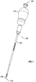
- FIG. 1 is a diagrammatic representation of a pedicle access tool (PAT) 100 that can be used to prepare a vertebra for a bone screw and to facilitate posterolateral fusion.
- PAT pedicle access tool
- PAT 100 comprises a cannula 102, a cannula handle 104 detachably coupled to cannula 102 and a stylet 106 that projects from cannula 102 and is removably coupled to handle 104.
- Cannula 102 and handle 104 form a continuous passage from proximate end 108 to distal end 110. According to one embodiment, the continuous passage is long enough to extend from a surgical site to the exterior of a patient's body.
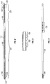
- Figure 2 is a diagrammatic representation of one embodiment of cannula 102 and Figure 3 is a diagrammatic representation of an end portion of cannula 102.
- Cannula 102 can define a passage 111 running from a proximate end 112 to a distal end 114.
- Cannula can include one or more features, such as indent 116, area 118 or other features to promote quick connection with handle 104. While a particular quick-connect embodiment is shown for an industry standard AO quick connect, embodiments of cannula 102 can include features compatible with any desired quick connect fitting. In other embodiments cannula 102 can include threads or fittings to detachably couple to handle 104.
- the tip 120 of cannula 102 can have a shape that is selected so that the tip 120 can perforate cortical bone such that cannula 102 acts as a bone awl.
- tip 120 can be a conical or other shape that transitions from a smaller to a larger diameter.
- Cannula 102 can also include a threaded tap section 122 that is selected to tap a hole made by stylet 106 and tip 120. Tip 120 can transition directly into tap section 122 or there may be some distance between tip 120 and tap section 122. According to one embodiment, cannula 102 can be selected to have a thread major diameter that is the same as or less than the major diameter of the bone screw to be installed.
- tap section 122 can have a major diameter of 4.0 mm for a screw with a major thread diameter of 4.5mm. In other embodiments, tap section 122 can have a major diameter of 4.0mm-4.5mm for a screw with a major diameter of 4.5mm. In yet another embodiment, tap section 122 can have a smaller major diameter. In some cases, if tap section 122 has too small of a major diameter, subsequent taps may be used. Tap section 122 can have any desired length along cannula 102.
- cannula 102 can have a generally cylindrical shape with a first section 124 and a second section 126.
- First section 124 can have a larger or smaller diameter than second section 126.
- tap section 122 has a major diameter that is less than or equal to the diameter of first section 124.
- Second section 126 can have a length selected so that pedicle access tool 100 only taps into a vertebra until shoulder 125 contacts the vertebra and limits further insertion.
- Figure 4 is a diagrammatic representation of another view of cannula 102 illustrating that tap section 122 can include a slot 128.
- Slot 128 can be sized to allow bone material to move into passage 111 when cannula 102 is used to tap bone.
- Cannula 102 can include other features to aid in surgery including, for example, depth markings 130, size markings or other indicia that can aid in surgery.
- Figure 5 is a diagrammatic representation of tool handle 104.
- Tool handle 104 can have an ergonomic shape, such as a rounded shape, a "T" shape or other ergonomic shape.
- Tool handle 104 can include a quick connect 132 to allow for easy detachable connection to cannula 102. While cannula 102 and handle 104 are shown as using an AO quick connect in Figures 2 and 5 , quick connect 132 can include industry standard quick connect or proprietary quick connect fitting. In other embodiments, tool handle 104 can detachably couple to cannula 102 in other manners such as, but not limited to, using threads, pins or suitable quick connect or non-quick connect connections.
- Tool handle 104 can connect to cannula 102 so that passage 134 forms a continuous passage with passage 111 of cannula 102.
- Handle 104 and cannula 102 can, in one embodiment, form a seal so that fluids can flow from cannula 102 through handle 104 without leaking at the connection.
- Handle 104 can be a ratcheting handle to facilitate tapping.
- Handle 104 can also detachably couple to stylet 106.
- handle 104 can include a Luer lock connection, a reverse thread Luer lock connection 136, quick connect connection or other connection to detachably couple to stylet 106.
- the connection between handle 104 and stylet 106 can allow stylet 106 to be positioned in various positions so that the tip of stylet 106 extends a desired distance from the tip of cannula 102.
- Figure 6 is a diagrammatic representation of one embodiment of stylet 106 including a stylet handle 138 and stylet needle 140.
- Needle 140 is long enough so that tip 142 extends beyond tip 120 of cannula 102 (shown in Figure 7 ).
- Tip 142 of needle 140 can be sharp enough to sink into pedicle bone.
- Handle 138 can include threads 144 or other connection to detachably couple to handle 104.
- Handle 138 can have a shape that is selected so that it is relatively easy for a surgeon to uncouple stylet 106 from handle 104 and withdraw stylet 106 from PAT 100.
- Figure 7 is a diagrammatic representation of one embodiment of a portion of PAT 100 proximate to distal end 110 including tip 142 of needle 140, tip 120 of cannula 102 and tap section 122 of cannula 102.
- the tip 142 can extend a select distance beyond tip 120 so that there is a desired distance "d1" to the start of tap section 120.
- d1 can be 20mm.
- d1 range from 5 mm to 30 mm. Other distances can be used as needed or desired for a particular procedure.
- the connection between handle 104 and stylet 106 can, in an embodiment, allow the surgeon to select how far tip 142 extends beyond cannula 102 to achieve a desired d1.
- Tip 142 can have various configurations.
- Figure 8A is a diagrammatic representation showing a trocar tip while
- Figure 8B is a diagrammatic representation showing another embodiment of a tip.
- tip 142 can have any suitable shape for piercing vertebral bone, including, but not limited to, beveled and trocar tips.
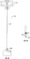
- Figure 9A illustrates another embodiment of a PAT 150 having a cannula 152, handle 154 and stylet 156 extending from cannula 152.
- handle 154 is a "T" shaped handle and cannula 152 has a constant diameter along most of its length.
- Figure 9B illustrates a portion of PAT 150 showing tip 160, tap section 162 and stylet tip 166.
- Stylet tip 156 can be sufficiently sharp to pierce vertebral bone.
- Tip 160 of cannula 152 can have tapered, conical or other shape that allows cannula 152 to act as an awl to puncture through the cortical bone of the vertebra.
- Tap section 162 can include a set of mini-threads that allow cannula 152 to be screwed into the hole formed by tip 160.
- the threads in one embodiment, can have a smaller diameter and smaller pitch than the threads of the bone screw to be inserted. According to one embodiment, the same cannula 152 can be used regardless of the size screw being inserted and subsequent taps can be used to increase the diameter of the hole.
- Embodiments of pedicle access tools can include a cannula and needles formed of biocompatible materials including titanium, PEEK, stainless steel or other material.
- cannula 102 may have some flexibility, it can be rigid enough so that, unlike a k-wire, it does not easily bend when manipulated or bumped by a surgeon. Portions of the tool not inserted into the body can be made of metal, plastic or other suitable material.
- the pedicle access tool can be formed of a sterilized material and be disposable or constructed to be autoclaved.
- cannula 102 and needle 140 can be formed of a material that can be discerned during medical imaging such as fluoroscopy, while the handles are made of a radio-lucent material.
- Embodiments of a pedicle access tool can act as an awl, tap and cannula reducing the number of tools required for a surgery. Furthermore, because the cannula can thread into the vertebra, the cannula can be secured to the bone during surgery. Consequently, the cannula, rather than a k-wire, can be used to guide some tools to a surgical site. Tools such as rasps, tamps, dilators, taps and others can be adapted to use cannula 102 as a guide.
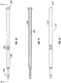
- FIG 10 is a diagrammatic representation of one embodiment of a bone rasp 200 that includes a rasp end 202 having teeth or other features adapted to roughen, bloody or otherwise prepare the surface of a vertebra for bone graft material.
- Rasp 200 can also include a portion 204 adapted for quick connection or other connection to a handle.
- Rasp 200 can include depth markings 206 or other features to aid in surgery.
- FIG 11 is a cross-sectional view of one embodiment of bone rasp 200 showing passage 208.
- Passage 208 is open at rasp end 202 and can have a diameter so that bone rasp 200 can fit over cannula 102.
- passage 208 can be as small as possible to preserve the working surface area of rasp end 202 while still allowing rasp 200 to fit over cannula 102.
- Passage 208 can run through the entire length of rasp 200 or can terminate in rasp 200.
- Passage 208 can be centered or offset from the center of bone rasp 200.
- a portion of passage 208 can be open to a slot on the side of rasp 200 so that rasp 200 can be angled relative to cannula 102 as discussed below in conjunction with Figure 23 .
- the outer of diameter of rasp 200 can be selected so that rasp 200 is small enough to fit inside a selected size dilator.
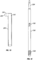
- Figure 12 is a diagrammatic representation of one embodiment of an offset rasp 210 that include a rasp body 212 and a rasp end 214.
- Rasp end 214 can have teeth or other features adapted to roughen, bloody or otherwise prepare bone for a bone graft.
- rasp 210 can be sized to fit into a dilator next to cannula 102 or a k-wire.
- Figure 13 is a diagrammatic representation of a dilator 220 that defines a passage 222 having a size to accommodate a selected rasp or other tool.
- Dilator 220 can include an extension 224 having a passage 226 sized to fit over cannula 102 or a k-wire.
- Figure 14 is a diagrammatic representation of a tap 230 that can include a threaded section 232 to tap a hole in preparation for a bone screw.
- a particular sized tap 230 can be chosen based on the size of bone screw to be inserted.
- a passage can accommodate cannula 102 or a k-wire so that tap 230 can fit over cannula 102.
- Tap 230 can include a portion 234 adapted for connection with a handle or can include a non-detachable handle. Tap 230 can include depth markings or other features to aid in surgery.
- PAT 100 can be used to aid in preparing a surgical site for installation of bone screws and to aid in posterolateral fusion.
- minimally invasive procedures a small opening may need to be made in a patient.
- the surgical procedure may be performed through a 2 cm to 4 cm incision formed in the skin of the patient.
- the incision may be above and substantially between the vertebrae to be stabilized.
- the incision may be above and substantially halfway between the vertebrae to be stabilized.
- the PAT, dilators, and/or a tissue wedge may be used to provide access to the vertebrae to be stabilized without the need to form an incision with a scalpel through muscle and other tissue between the vertebrae to be stabilized.
- a minimally invasive procedure may reduce an amount of postoperative pain felt by a patient as compared to invasive spinal stabilization procedures and reduce recovery time for the patient as compared to invasive spinal procedures.
- Embodiments of posterolateral fusion described herein can be performed as a minimally invasive procedure.
- FIGs 15A, 15B and 15C are diagrammatic representations of introducing PAT 100 into the bone.
- a surgeon selects the surgical site and guides PAT 100 to the surgical using medical imaging until tip 142 contacts bone.
- the surgical site is the pedicle (represented at 302) of a vertebra.
- Figure 15B illustrates tip 142 inserted into the bone.
- the surgeon can force tip 120 through the bone by gently tapping on handle 104 with a mallet or otherwise driving tip 120 into the cortical bone.
- PAT 100 can be turned using handle 104 to cause tap section 122 to tap a hole 304 a selected depth as shown in Figure 15C . Shoulder 125 can prevent PAT 100 from penetrating too deeply into pedicle 302.
- PAT 100 can act as a targeting needle, awl and tap in a single tool.
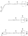
- FIG 16 is a diagrammatic representation of tool 100 in pedicle 302 with stylet 106 removed.
- a syringe can be connected to connection 134 and tissue aspirated through cannula 102 and handle 104.
- an aspiration step can occur later or not occur at all.
- handle 104 can be removed.
- FIG 18 is a diagrammatic representation of an embodiment of performing aspiration through cannula 102.
- a syringe 308 can be connected to cannula 102 using a quick connect adapter 310 or other mechanism to connect to cannula 102.
- Syringe 308 can be used to aspirate a desired amount of bone marrow or other material through cannula 102.
- Tissue around cannula 102 can be dilated using one or more dilators that fit over cannula 102 to dilate tissue a desired amount.
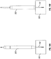
- Figures 19A and B are diagrammatic representations of sequentially dilating tissue about cannula 102 using dilator 320 and then larger dilator 322.
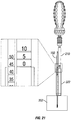
- the depth markings 130 on cannula 102 can show the depth of tip 120 past dilator 322.
- rasp 200 can be guided down cannula 102 to the vertebra.
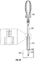
- Figure 20 is a diagrammatic representation of rasp 200 in place over cannula 102 and inside dilator 322.
- a handle 324 can be used to manipulate rasp 200.
- handle 324 can be the same handle as handle 104 or can be a modular handle used with other tools such as drivers.
- Depth markings on rasp 200 indicate the depth of rasp end 202 relative to the end of dilator 322.
- Rasp 200 can be used to de-corticate or otherwise prepare the pedicle surface for a bone graft.
- rasp 200 is an in-line rasp that is coaxial with cannula 102 and that prepare the bone around cannula 102 up to the diameter of rasp 200. Areas further offset from cannula 102 can be prepared including, for example, inferior and superior facet surfaces.
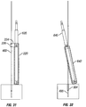
- Figure 21 is a diagrammatic representation of a rasp 210 that fits next to cannula 102 in dilator 322. Rasp 210 and dilator 322 can be moved in a circle around cannula 102 to prepare a larger area.
- Figure 22 is a diagrammatic representation of a rasp 210 used in conjunction with a dilator 220. Dilator 220 can be rotated about cannula 102 using extension 224. In one embodiment multiple dilators can be used having different lengths of extension 224 so that rasp 330 can prepare areas closer to and further away from cannula 102.
- Figure 23 is a diagrammatic representation of another embodiment of preparing bone.
- a single rasp 340 can be used to prepare the bone both immediately around and further away from cannula 102.
- Rasp 340 and dilator 342 can include slots in their walls so that they can tilt relative to cannula 102.
- Rasp 340 can be oriented coaxial with cannula 102 to prepare an area close to cannula 102 and tilted at various angles to prepare a larger area.
- Bone graft or other fusion promoting materials can be placed across de-corticated or otherwise prepared surfaces for posterolateral fusion.
- Examples of bone fusion promoting materials include, but are not limited to, illac crest autographs, bone grafts from other sources, bone morphogenetic proteins or other bone fusion materials.
- Figures 24 is a diagrammatic representation of one embodiment of introducing bone fusion material.
- a disc of fusion promoting 350 that has a hole large enough to fit over cannula 102 is lead to the surgical site down cannula 102.
- the hole can be large enough so that the shaft of a bone screw can pass through the hole, but the collar or head of the bone screw will press disc 350 into the vertebra when the bone screw is secured.
- the fusion material can be introduced as particles 352 that can be poured down dilator 320.
- both a disc (or other shaped piece) of bone fusion promoting material and particles can be used together.
- a disc 350 can be used at the center of an area and particles used in a broader area.
- a tamp can be used to press the bone graft material into the prepared area.
- Figure 25 illustrates and embodiment of a tamp 360 pressing on bone fusion material 350.
- tamp 360 can include a tamp body 362 that is small enough to fit in dilator 322 and a generally flat tamping end 364. Tamp 360 can further include a passage at the center of tamp 360 or offset from the center of tamp 360 that can accommodate cannula 102. While a particular embodiment of an in-line tamp is shown, various embodiments of inline and offset tamps can be similar to previously discussed embodiments of rasps, but with flat or otherwise shaped tamping ends to press the bone fusion material into the prepared bone.
- FIG 26 is a diagrammatic representation of installing a k-wire 400.
- K-wire 400 can be formed of stainless steel, nitinol or other material.
- K-wire 400 is advanced through cannula 102 until the tip 404 of k-wire 400 is advanced beyond tip 120 of cannula 102 into the vertebra.
- a dilator or other support 402 can be used to hold the k-wire straight. If needed, a mallet or other tool can be used to drive the k-wire. Installation of the k-wire can be monitored under Fluoroscopy or other medical imaging.
- Figure 27 is a diagrammatic representation of one embodiment of removing cannula 102.
- handle 104 can be lead down k-wire 400 and reattached to cannula 102.
- Cannula 102 can then be unthreaded from the vertebral body leaving k-wire 400 inserted in the bone through the end of hole 304 as shown, for example, in Figure 28 .
- K-wire 400 can be used to guide bone screws or other tools to the surgical site.
- a spinal stabilization system can be installed in the body using k-wire 400.
- the spinal stabilization system can include bone anchor assemblies that secure a rigid or dynamic stabilization rod.
- the bone anchor assemblies can be lead to the surgical site using k-wire 400 according to methods known or developed in the art. If a disc 350 of bone fusion promoting material is inserted as described above, the shaft of a bone anchor assemblies can pass through the hole in disc 350 while the collar presses bone fusion promoting material into the respective vertebrae. Over time, discs 350 or other bone fusion material will promote bone growth between the vertebrae to cause vertebrae to fuse together adding stability to the spine.
- cannula 102 as a guide provides the advantage of using a k-wire for fewer steps. Because tip 120 is relatively blunt compared to the tip of a k-wire, it is less likely that cannula 120 will push through a vertebra if inadvertently pushed during surgery. Furthermore, cannula 102 can be easier to manage because it is more rigid than a k-wire and can remain in one place during surgery.
- k-wire 400 as a guide rather than cannula 102.
- Various tools can be sized to fit over the k-wire. These may be the same tools that can fit over cannula 102 or can be tools with smaller diameter passages that can be guided down the k-wire 400.
- the k-wire 400 can be installed using PAT 100 or other targeting needle. If PAT 100 is not used, separate awls and taps can guided down k-wire 400 to form hole 304.
- k-wire 400 can be used as a guide for any number of steps for promoting posterolateral fusion.
- Figure 29 is a diagrammatic representation of rasp 600 in place over k-wire and inside dilator 322.
- a handle can be used to manipulate rasp 600.
- the handle can be the same handle as handle 104 or can be a modular handle used with other tools such as drivers.
- Rasp 600 can be selected so that the depth markings on rasp 600 indicate the depth of rasp end 602 relative to the end of dilator 322.
- Rasp 600 can be used to de-corticate or otherwise prepare the pedicle surface for a bone graft.
- Rasp 600 can be similar to rasp 200, but can have a smaller passage to accommodate k-wire 400.
- a rasp with a larger diameter passage, such as rasp 200 can be used over k-wire 400.
- rasp 600 is an in-line rasp that is coaxial with k-wire 400 and prepares the bone around cannula k-wire 400 sup to the diameter of rasp 600. Areas further offset from k-wire 400 can be prepared including, for example, inferior and superior facet surfaces.
- Figure 30 is a diagrammatic representation of using a rasp 635 that fits in dilator 322 next to k-wire 400. Dilator 322 can be rotate about k-wire 400 so that rasp 635 can prepare a larger area.
- Figure 31 is a diagrammatic representation of a rasp 638 used in conjunction with a dilator 220. Dilator 220 can be rotated about k-wire 400 using extension 224.
- multiple dilators can be used having different lengths of extension 224 so that rasp 330 can prepare areas closer to and further away from cannula k-wire 400. While, in this example, extension 224 can be sized to fit over either cannula 102 or k-wire 400, in other embodiments, extension 224 can be sized to fit over k-wire 400 but not cannula 102.
- Figure 32 is a diagrammatic representation of another embodiment of preparing bone.
- a single rasp 640 can be used to prepare the bone both immediately around and further away from k-wire 400.
- Rasp 640 and dilator 642 can include slots in their walls so that they can tilt relative to cannula k-wire 400.
- Rasp 640 can be oriented be coaxial with k-wire 400 or tilted at various angles relative to k-wire 400 to prepare a larger area.
- Figure 33 is a diagrammatic representation of one embodiment of introducing bone fusion material.
- a disc of fusion promoting material 650 has a hole that is large enough to fit over k-wire 400 so that it can be lead to the surgical over k-wire 400.
- the hole can be large enough so that the shaft of a bone screw can pass through the hole, but the collar or head of the bone screw will press disc 650 into the vertebra when the bone screw is secured.
- Figure 33 also illustrates that bone fusion material can be introduced as particles 652 that can be poured down dilator 322 rather than or in addition to using disc 650.
- a tamp can be used to press the bone graft material into the prepared area.
- Figure 34 illustrates an embodiment of a tamp 660 pressing on bone fusion material 650.
- tamp 660 can include a tamp body 662 that is small enough to fit in dilator 322 and a generally flat tamping end 664.
- Tamp 660 can further include a passage at the center of tamp 660 or offset from the center of tamp 660 that can accommodate k-wire 400. While a particular embodiment of an in-line tamp is shown, various embodiments of in-line and offset tamps can be similar to previously discussed embodiments of rasps but with flat or otherwise shaped tamping ends to press the bone fusion material.
- k-wire 400 can also be used as guide in various steps of a posterolateral fusion procedure.
- the k-wire can be introduced using a targeting needle or PAT 100.
- PAT 100 can be used to form and tap a hole and then be removed.
- K-wire 400 can be used as a guide for the remainder of the procedure.
- cannula 102 can be used during the rasping stages and the removed while k-wire 400 can be used when bone fusion material is introduced and during tamping.
- cannula 102 can be used to guide bone fusion material to a site and k-wire 400 used to guide a tamp to the site.
- k-wire 400 used to guide a tamp to the site.
- a rasp can be lead to a surgical site using a rasp guide
- a tamp can be lead to the surgical site using a tamp guide
- bone fusion promoting material can be lead to the surgical site using a bone fusion promoting material guide.
- the guide in each step can be a cannula, k-wire or other guide.
- the cannula of pedicle access tool can be used as the guide for various steps. Additional tools, such as a tap or other tool, can be lead to a surgical site using a cannula of a pedicle access tool or a k-wire as needed or desired.
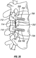
- FIG 35 illustrates an embodiment of a spinal stabilization system 700 installed on vertebra prepared to promote posterolateral fusion.
- Spinal stabilization system 700 can include bone anchors 702 and 704 installed in vertebrae 706 and 708 respectively.
- Bone anchors 702 and 704 can be polyaxial or monoaxial bone screws or other bone anchors known in the art.
- the bone anchors can be cannulated so that they can pass over a k-wire.
- Each bone anchor can include a collar (e.g., collars 710 and 712) that secures a rigid or dynamic spinal stabilization rod 714.
- collars 710 and 712 press a disc of bone fusion promoting material 350 into an area of the pedicle prepared by a rasp. Additional bone fusion promoting material 352 can be placed further away from bone anchors 702 and 704 to promote a broader region of fusion. Over time, bone will fuse between vertebrae 706 and 708 to stabilize the spine.
- the invention can be used in a method for spinal fusion comprising:
- the method can further comprise:
- the method can further comprise guiding a rasp down the cannula.
- guiding the rasp down the cannula can comprise guiding an inline rasp down the cannula, and the method can further comprise roughening a first area of bone using the inline rasp.
- the method can further comprise guiding an offset rasp next to the cannula in a dilator and roughening a second area of bone further away from the cannula than the first area of bone.
- the method can further comprise using the cannula to guide bone fusion promoting material to the surgical site, wherein the bone fusion promoting material comprises a piece of material defining a hole to fit over the cannula.
- the method can further comprise leading a tamp to the surgical site using the cannula and tamping the bone fusion promoting material.
- the method can further comprise inserting the k-wire through a cannula and removing the cannula.
- the method can further comprise:
- installing the second bone anchor can further comprise installing the second bone anchor so that a shaft of the second bone anchor passes through a hole in a second piece of bone fusion promoting material and a collar of the second bone anchor presses the second piece of bone fusion promoting material into the second vertebra.
- the method can further comprise placing additional bone fusion promoting material in an area between the first bone anchor and second bone anchor.
- the invention can be used in a method for posterolateral fusion comprising:
- installing the second bone anchor assembly to the second vertebra can further comprise securing the second bone anchor so that a collar of the second bone anchor presses a second piece of bone fusion promoting material into a roughened area of the second vertebra, wherein the first piece of bone fusion promoting material and second piece of bone fusion promoting material are positioned to promote posterolateral fusion.
- the method can further comprise disposing additional bone fusion promoting material between the first and second pieces of bone fusion promoting material.
- steps for a posterolateral fusion described herein can be used to promote fusion at other portions of the spine.
- steps for a posterolateral fusion described herein can be used to promote fusion at other portions of the spine.
- other guides as needed or desired can be used.
Landscapes
- Health & Medical Sciences (AREA)
- Life Sciences & Earth Sciences (AREA)
- Surgery (AREA)
- Orthopedic Medicine & Surgery (AREA)
- Animal Behavior & Ethology (AREA)
- General Health & Medical Sciences (AREA)
- Biomedical Technology (AREA)
- Heart & Thoracic Surgery (AREA)
- Medical Informatics (AREA)
- Molecular Biology (AREA)
- Nuclear Medicine, Radiotherapy & Molecular Imaging (AREA)
- Engineering & Computer Science (AREA)
- Public Health (AREA)
- Veterinary Medicine (AREA)
- Dentistry (AREA)
- Oral & Maxillofacial Surgery (AREA)
- Neurology (AREA)
- Pathology (AREA)
- Surgical Instruments (AREA)
- Prostheses (AREA)
Claims (14)
- Outil d'accès au pédicule, comprenant :une canule (102) comprenant :un corps de canule définissant un premier passage (111) à travers la canule ;un embout (120) à l'extrémité de la canule, adapté à faire office d'alène pour os ;une section filetée (122) disposée autour d'un extérieur d'une seconde section (126) à une distance sélectionnée depuis l'embout, la section filetée étant adaptée à faire office de tarière pour os ;une poignée de canule (104) couplée de façon détachable à la canule et définissant un second passage à travers la poignée de canule, qui forme un passage continu avec le premier passage ; etun stylet (106) comprenant :caractérisé en ce queune poignée d'aiguille (138) couplée de façon détachable à la poignée de canule ; etune aiguille (140) couplée à la poignée d'aiguille, l'aiguille passant à travers le passage continu et comprenant un embout d'aiguille (142) qui s'étend au-delà de l'embout de la canule ;
le corps de canule définit une fente (128) dans la section filetée pour permettre à un matériau de passer jusque dans le premier passage. - Outil d'accès au pédicule selon la revendication 1, dans lequel la poignée d'aiguille (140) est couplée à la poignée de canule (104) pour permettre de sélectionner la distance sur laquelle l'embout d'aiguille (142) s'étend au-delà de l'embout de canule.
- Outil d'accès au pédicule selon la revendication 1 ou 2, dans lequel la canule comprend une première section (124) d'un premier diamètre, la seconde section (126) d'un second diamètre, un épaulement (125) formant une transition depuis la première section vers la seconde section, dans lequel l'épaulement est placé de manière à limiter la distance sur laquelle une canule peut passer jusque dans une vertèbre.
- Outil d'accès au pédicule selon l'une quelconque des revendications 1 à 3, dans lequel la poignée de canule (104) est une poignée en forme de "T".
- Outil d'accès au pédicule selon l'une quelconque des revendications 1 à 4, dans lequel l'embout d'aiguille (142) est un embout en trocart.
- Outil d'accès au pédicule selon l'une quelconque des revendications 1 à 5, dans lequel la poignée de canule (104) est couplée de façon détachable à la canule par un raccord de connexion rapide.
- Outil d'accès au pédicule selon l'une quelconque des revendications 1 à 6, dans lequel la canule inclut des marquages de profondeur (130).
- Outil d'accès au pédicule selon l'une quelconque des revendications 1 à 7, dans lequel la poignée de canule est une poignée à cliquet.
- Trousse chirurgicale comprenant :un outil d'accès au pédicule comprenant :une canule (102) comprenant :un corps de canule définissant un premier passage (111) à travers la canule ;un embout (120) à l'extrémité de la canule, adapté à faire office d'alène pour os ;une section filetée (122) disposée autour d'un extérieur d'une seconde section (126) à une distance sélectionnée depuis l'embout, la section filetée étant adaptée à faire office de tarière pour os, dans laquelle le corps de canule définit une fente (128) dans la section filetée pour permettre à un matériau de passer jusque dans le premier passage ;une poignée de canule (104) couplée de façon détachable à la canule et définissant un second passage à travers la poignée de canule, qui forme un passage continu avec le premier passage ; etun stylet (106) comprenant :une poignée d'aiguille (138) couplée de façon détachable à la poignée de canule ; etune aiguille (140) couplée à la poignée d'aiguille, l'aiguille passant à travers le passage continu et comprenant un embout d'aiguille (142) qui s'étend au-delà de l'embout de la canule ;un dilatateur (220) configuré pour créer un passage à travers un corps jusqu'à un site chirurgical.
- Trousse chirurgicale selon la revendication 9, comprenant en outre : un fil "k" ayant un diamètre plus petit que le premier passage.
- Trousse chirurgicale selon la revendication 9 ou 10, comprenant en outre une râpe (200) d'une taille propre à se loger dans le dilatateur (220) avec la canule,
- Trousse chirurgicale selon la revendication 11, dans laquelle la râpe (200) définit un passage (208) à travers la râpe, de sorte que la râpe peut être guidée jusqu'au site chirurgical par-dessus la canule.
- Trousse chirurgicale selon la revendication 11 ou 12, dans laquelle la râpe (200) définit une fente de sorte que la râpe peut être disposée sous un angle par rapport à la canule.
- Trousse chirurgicale selon l'une quelconque des revendications 11 à 13, dans laquelle la râpe (200) a une taille propre à se loger dans le dilatateur (220) à la suite de la canule.
Applications Claiming Priority (1)
| Application Number | Priority Date | Filing Date | Title |
|---|---|---|---|
| US12/550,235 US8814914B2 (en) | 2009-08-28 | 2009-08-28 | Fusion method and pedicle access tool |
Publications (3)
| Publication Number | Publication Date |
|---|---|
| EP2289433A2 EP2289433A2 (fr) | 2011-03-02 |
| EP2289433A3 EP2289433A3 (fr) | 2014-01-08 |
| EP2289433B1 true EP2289433B1 (fr) | 2017-05-10 |
Family
ID=43304779
Family Applications (1)
| Application Number | Title | Priority Date | Filing Date |
|---|---|---|---|
| EP10008297.3A Not-in-force EP2289433B1 (fr) | 2009-08-28 | 2010-08-09 | Outil d'accès au pédicule |
Country Status (2)
| Country | Link |
|---|---|
| US (1) | US8814914B2 (fr) |
| EP (1) | EP2289433B1 (fr) |
Cited By (1)
| Publication number | Priority date | Publication date | Assignee | Title |
|---|---|---|---|---|
| US11937857B2 (en) | 2013-03-14 | 2024-03-26 | DePuy Synthes Products, Inc. | Bone anchors and surgical instruments with integrated guide tips |
Families Citing this family (65)
| Publication number | Priority date | Publication date | Assignee | Title |
|---|---|---|---|---|
| JP5146447B2 (ja) | 2006-04-11 | 2013-02-20 | ジンテス ゲゼルシャフト ミット ベシュレンクテル ハフツング | 最小侵襲性固定システム |
| WO2010031064A1 (fr) | 2008-09-15 | 2010-03-18 | Clearview Patient Safety Technologies, Llc | Dispositif de détection pour ponction lombaire |
| US9808281B2 (en) | 2009-05-20 | 2017-11-07 | DePuy Synthes Products, Inc. | Patient-mounted retraction |
| US8814914B2 (en) * | 2009-08-28 | 2014-08-26 | Zimmer Spine, Inc. | Fusion method and pedicle access tool |
| US9204906B2 (en) | 2009-10-22 | 2015-12-08 | Nuvasive, Inc. | Posterior cervical fusion system and techniques |
| US10098674B2 (en) | 2009-10-22 | 2018-10-16 | Nuvasive, Inc. | System and method for posterior cervical fusion |
| US8545505B2 (en) | 2010-01-15 | 2013-10-01 | Pioneer Surgical Technology, Inc. | Low friction rod persuader |
| US8535318B2 (en) | 2010-04-23 | 2013-09-17 | DePuy Synthes Products, LLC | Minimally invasive instrument set, devices and related methods |
| US8641717B2 (en) | 2010-07-01 | 2014-02-04 | DePuy Synthes Products, LLC | Guidewire insertion methods and devices |
| WO2012166495A1 (fr) | 2011-05-27 | 2012-12-06 | Synthes Usa, Llc | Système de fixation vertébrale minimalement invasif comprenant des caractéristiques d'alignement vertébral |
| US20130150752A1 (en) * | 2011-12-12 | 2013-06-13 | Karl W. Swann | Apparatus for Bone Aspiration |
| WO2013106726A1 (fr) | 2012-01-12 | 2013-07-18 | Wyatt Drake Geist | Ensemble d'accès pour des interventions rachidiennes antérieures et latérales |
| US20130289572A1 (en) * | 2012-04-25 | 2013-10-31 | Kyphon Sarl | Positional guide |
| US9226756B2 (en) | 2012-05-14 | 2016-01-05 | DePuy Synthes Products, Inc. | Bone access instrument |
| EP3281609B1 (fr) * | 2012-05-29 | 2019-02-27 | NLT Spine Ltd. | Implant expansible |
| US10194967B2 (en) * | 2012-09-21 | 2019-02-05 | Atlas Spine, Inc. | Minimally invasive spine surgery instruments: guide wire handle with a guide wire locking mechanism |
| US9414868B1 (en) * | 2012-12-13 | 2016-08-16 | Spinelogik, Inc. | Guide placement device and method of use |
| CN103054623B (zh) * | 2013-01-15 | 2015-03-11 | 温州医学院附属第一医院 | 脊柱内镜下经椎间孔入路手术中的椎间孔扩孔工具 |
| US9237894B2 (en) * | 2013-01-31 | 2016-01-19 | Depuy Mitek, Llc | Methods and devices for forming holes in bone to stimulate bone growth |
| US10342498B2 (en) * | 2013-02-21 | 2019-07-09 | Medtronic Holding Company Sàrl | Cannula with image markers to indicate expandable device size |
| KR20160104544A (ko) * | 2013-03-15 | 2016-09-05 | 비다케어 엘엘씨 | 골내 디바이스 핸들, 시스템, 및 방법 |
| US10149770B2 (en) | 2013-07-09 | 2018-12-11 | Seaspine, Inc. | Orthopedic implant with adjustable angle between tissue contact surfaces |
| US20150100077A1 (en) * | 2013-10-09 | 2015-04-09 | Safewire, LLC | Thread forming jamshidi assembly |
| WO2015063721A1 (fr) | 2013-10-31 | 2015-05-07 | Nlt Spine Ltd. | Implant réglable |
| US9968373B1 (en) * | 2014-02-21 | 2018-05-15 | Surgentec, Llc | Handles for needle assemblies |
| CN104287815B (zh) * | 2014-06-16 | 2017-01-11 | 南通舟可信息科技有限公司 | 3d打印经皮椎弓根导板及其制备方法和使用方法 |
| WO2015198335A1 (fr) | 2014-06-25 | 2015-12-30 | Nlt Spine Ltd. | Implant expansible avec bras articulés |
| US9855087B2 (en) | 2014-08-04 | 2018-01-02 | DePuy Synthes Products, LLC | Methods and devices for spinal screw insertion |
| US20180049754A1 (en) * | 2015-03-13 | 2018-02-22 | Redemed S.R.L. | Intervertebral prosthesis, apparatus for implanting intervertebral prostheses and surgical method for implanting intervertebral prostheses, particularly for percutaneous mini-invasive surgery procedures |
| US10123829B1 (en) | 2015-06-15 | 2018-11-13 | Nuvasive, Inc. | Reduction instruments and methods |
| US10136902B2 (en) * | 2015-07-31 | 2018-11-27 | Warsaw Orthopedic, Inc. | Surgical instrument and method |
| WO2017053813A1 (fr) | 2015-09-24 | 2017-03-30 | Integrity Implants, Inc. | Ensemble d'accès pour des opérations de la colonne vertébrale antérieure et latérale |
| CN105476707B (zh) * | 2015-10-30 | 2017-12-26 | 自贡市第四人民医院 | 一种个性化枕颈融合螺钉进钉导航模板的制作方法 |
| US9675363B2 (en) * | 2015-11-13 | 2017-06-13 | Advance Research System, Llc | Surgical tools having application for spinal surgical procedures and method of use |
| CN105596077A (zh) * | 2016-02-06 | 2016-05-25 | 贺新宁 | 一种椎弓根螺钉的通用置钉装置 |
| CN106137335A (zh) * | 2016-07-15 | 2016-11-23 | 于海龙 | 一种胸腰椎经皮穿刺装置及其使用方法 |
| JP6960133B2 (ja) * | 2016-08-19 | 2021-11-05 | 国立大学法人東北大学 | スクリューの補強材の挿入装置 |
| IL247684A0 (en) | 2016-09-07 | 2017-01-31 | Waismed Ltd | Tube for use in intraosseous injections |
| US11033341B2 (en) | 2017-05-10 | 2021-06-15 | Mako Surgical Corp. | Robotic spine surgery system and methods |
| EP3621545B1 (fr) | 2017-05-10 | 2024-02-21 | MAKO Surgical Corp. | Système robotique d'opération chirurgicale de la colonne vertébrale |
| US10973558B2 (en) | 2017-06-12 | 2021-04-13 | K2M, Inc. | Screw insertion instrument and methods of use |
| US10433883B2 (en) | 2017-06-27 | 2019-10-08 | Medos International Sarl | Spinal screw insertion devices and methods |
| US10779872B2 (en) | 2017-11-02 | 2020-09-22 | Medos International Sarl | Bone anchor insertion instruments and methods |
| US11666367B2 (en) * | 2018-05-30 | 2023-06-06 | Tushar Goradia | Guidance apparatus for implantation into bone and related methods of use |
| US11648000B2 (en) * | 2018-07-30 | 2023-05-16 | Braunvest Llc | Vertebral probes and related surgical methods |
| US12232781B2 (en) * | 2018-07-30 | 2025-02-25 | BraunVest, LLC | Cortical/cancellous bone probes and related surgical methods |
| USD948045S1 (en) | 2018-12-13 | 2022-04-05 | Spinal Generations, Llc | Bone instrument shank |
| US11602357B2 (en) * | 2018-12-13 | 2023-03-14 | Spinal Generations, Llc | Drill bit with delivery device fitting and method of use thereof |
| US11633223B2 (en) | 2018-12-20 | 2023-04-25 | Integrity Implants Inc. | Surgical guidance device |
| US11344353B2 (en) | 2018-12-20 | 2022-05-31 | Integrity Implants Inc. | Surgical guidance device and system for insertion thereof |
| US11484351B2 (en) | 2018-12-20 | 2022-11-01 | Integrity Implants Inc. | Surgical device for insertion of guide wire and pedicle screw |
| US11123113B2 (en) | 2019-06-13 | 2021-09-21 | Medos International Sarl | Screw inserter instruments and methods |
| US11224472B2 (en) | 2019-06-13 | 2022-01-18 | Medos International Sarl | Screw inserter instruments and methods |
| US11612419B2 (en) * | 2020-01-24 | 2023-03-28 | Warsaw Orthopedic, Inc. | Spinal implant system and method |
| CN111358599A (zh) * | 2020-03-03 | 2020-07-03 | 广东施泰宝医疗科技有限公司 | 一种可原位植骨和二次植骨椎间融合器及其配套工具 |
| KR20220159392A (ko) | 2020-03-27 | 2022-12-02 | 마코 서지컬 코포레이션 | 햅틱 인터페이스를 이용한 로봇 척추 수술 시스템 및 방법 |
| EP3892215B1 (fr) * | 2020-04-09 | 2023-10-11 | Biedermann Technologies GmbH & Co. KG | Instrument chirurgical |
| US12262927B2 (en) | 2020-12-10 | 2025-04-01 | K2M, Inc. | Screw insertion instrument and methods of use |
| US12605257B2 (en) | 2020-12-23 | 2026-04-21 | Formae, Inc. | Instruments and methods for preparing patient recipient site and installing medical implant |
| CN113262034B (zh) * | 2021-06-04 | 2025-03-18 | 北京市富乐科技开发有限公司 | 枢椎椎体骨折复位手术器械 |
| US20250009362A1 (en) * | 2021-11-18 | 2025-01-09 | Phasor Health, Llc | Quick-connect k-wire module |
| KR20230122791A (ko) * | 2022-02-15 | 2023-08-22 | 신흥섭 | 척추 유합술용 뼈고정기구 및 이를 포함하는 수술도구 세트 |
| AU2023278867A1 (en) | 2022-06-03 | 2025-01-09 | Mako Surgical Corp. | Surgical robotic system with compliance mechanism |
| US20250082381A1 (en) * | 2023-09-12 | 2025-03-13 | Conventus Orthopaedics, Inc. | Cannulated implant removal tools and method |
| CN118512233B (zh) * | 2024-05-24 | 2025-03-14 | 董岩 | 一种可调肩峰骨刀 |
Family Cites Families (32)
| Publication number | Priority date | Publication date | Assignee | Title |
|---|---|---|---|---|
| DE7529790U (de) | 1975-09-20 | 1976-02-19 | Lysell, Ralf, 2340 Kappeln | Vorrichtung zum Vorbearbeiten eines Knochenkanales, in welchem ein Implantat einzementiert werden soll |
| US5946988A (en) * | 1992-02-27 | 1999-09-07 | Howmedica Gmbh | Tool for driving pedicle screws |
| US5196015A (en) * | 1992-04-30 | 1993-03-23 | Neubardt Seth L | Procedure for spinal pedicle screw insertion |
| US20030032963A1 (en) * | 2001-10-24 | 2003-02-13 | Kyphon Inc. | Devices and methods using an expandable body with internal restraint for compressing cancellous bone |
| US6019776A (en) * | 1997-10-14 | 2000-02-01 | Parallax Medical, Inc. | Precision depth guided instruments for use in vertebroplasty |
| DE29806563U1 (de) | 1998-04-09 | 1998-06-18 | Howmedica GmbH, 24232 Schönkirchen | Pedikelschraube und Montagehilfe dafür |
| US6770079B2 (en) * | 1999-03-16 | 2004-08-03 | American Osteomedix, Inc. | Apparatus and method for fixation of osteoporotic bone |
| US20030018337A1 (en) * | 2001-07-17 | 2003-01-23 | Davis Reginald J. | Bone drill and tap combination |
| US20030050644A1 (en) * | 2001-09-11 | 2003-03-13 | Boucher Ryan P. | Systems and methods for accessing and treating diseased or fractured bone employing a guide wire |
| GB2382028B (en) * | 2001-11-19 | 2006-11-01 | Aberdeen Orthopaedic Developme | Intervertebral disc prosthesis |
| US9782572B2 (en) * | 2002-09-30 | 2017-10-10 | Nordson Corporation | Apparatus and methods for treating bone structures, tissues and ducts using a narrow gauge cannula system |
| EP1567069A4 (fr) * | 2002-11-08 | 2008-11-12 | Warsaw Orthopedic Inc | Procedes et dispositifs d'acces transpediculaire aux disques intervertebraux |
| US20050171551A1 (en) | 2003-10-21 | 2005-08-04 | William Sukovich | Instrument and method for preparing a bone to receive an implant |
| US7699852B2 (en) * | 2003-11-19 | 2010-04-20 | Zimmer Spine, Inc. | Fenestrated bone tap and method |
| US8926700B2 (en) * | 2003-12-10 | 2015-01-06 | Gmedelware 2 LLC | Spinal facet joint implant |
| US20060030872A1 (en) * | 2004-08-03 | 2006-02-09 | Brad Culbert | Dilation introducer for orthopedic surgery |
| WO2007011755A2 (fr) * | 2005-07-14 | 2007-01-25 | Globus Medical, Inc. | Dispositif de marquage vertebral et methodes de mise en place |
| US8192443B2 (en) * | 2006-04-21 | 2012-06-05 | Mi4Spine, Llc | Pedicle access device |
| EP2046207A4 (fr) | 2006-07-13 | 2017-08-23 | K2M, Inc. | Dispositifs et procedes pour stabiliser une region spinale |
| US20080051793A1 (en) * | 2006-08-04 | 2008-02-28 | David Erickson | Drill-tap tool |
| US8137352B2 (en) * | 2006-10-16 | 2012-03-20 | Depuy Spine, Inc. | Expandable intervertebral tool system and method |
| US7862502B2 (en) * | 2006-10-20 | 2011-01-04 | Ellipse Technologies, Inc. | Method and apparatus for adjusting a gastrointestinal restriction device |
| US8328815B2 (en) * | 2006-11-03 | 2012-12-11 | Innovative Spine, Llc. | Surgical access with target visualization |
| US20080108991A1 (en) * | 2006-11-08 | 2008-05-08 | General Electric Company | Method and apparatus for performing pedicle screw fusion surgery |
| US8052720B2 (en) * | 2006-11-09 | 2011-11-08 | Zimmer Spine, Inc. | Minimally invasive pedicle screw access system and associated method |
| US20080300605A1 (en) * | 2007-06-01 | 2008-12-04 | Rinner James A | Pedicle protractor tool |
| US20110098628A1 (en) * | 2007-07-25 | 2011-04-28 | Yeung Jeffrey E | Internal and external disc shunts alleviate back pain |
| US7947064B2 (en) * | 2007-11-28 | 2011-05-24 | Zimmer Spine, Inc. | Stabilization system and method |
| US20090138043A1 (en) | 2007-11-28 | 2009-05-28 | Medtronic Spine Llc | Threaded access cannula and methods of using the same |
| US20100331891A1 (en) * | 2009-06-24 | 2010-12-30 | Interventional Spine, Inc. | System and method for spinal fixation |
| US8814914B2 (en) * | 2009-08-28 | 2014-08-26 | Zimmer Spine, Inc. | Fusion method and pedicle access tool |
| US9486234B2 (en) * | 2010-02-10 | 2016-11-08 | Eliaz Babaev | Surgical saw blade |
-
2009
- 2009-08-28 US US12/550,235 patent/US8814914B2/en active Active
-
2010
- 2010-08-09 EP EP10008297.3A patent/EP2289433B1/fr not_active Not-in-force
Cited By (2)
| Publication number | Priority date | Publication date | Assignee | Title |
|---|---|---|---|---|
| US11937857B2 (en) | 2013-03-14 | 2024-03-26 | DePuy Synthes Products, Inc. | Bone anchors and surgical instruments with integrated guide tips |
| US12551247B1 (en) | 2013-03-14 | 2026-02-17 | DePuy Synthes Products, Inc. | Bone anchors and surgical instruments with integrated guide tips |
Also Published As
| Publication number | Publication date |
|---|---|
| US8814914B2 (en) | 2014-08-26 |
| EP2289433A2 (fr) | 2011-03-02 |
| US20110054537A1 (en) | 2011-03-03 |
| EP2289433A3 (fr) | 2014-01-08 |
Similar Documents
| Publication | Publication Date | Title |
|---|---|---|
| EP2289433B1 (fr) | Outil d'accès au pédicule | |
| US8409257B2 (en) | Systems and methods for facet joint stabilization | |
| EP1684644B1 (fr) | Taraud fenestré pour os | |
| US9649138B2 (en) | Facet screw and method for spinal stabilization | |
| US9788843B2 (en) | Bone access instrument | |
| US9974573B2 (en) | Minimally invasive approaches, methods and apparatuses to accomplish sacroiliac fusion | |
| US7905884B2 (en) | Method for use of dilating stylet and cannula | |
| US20080119759A1 (en) | Method and apparatus for aspirating bone marrow | |
| EP2529668B1 (fr) | Appareil permettant d'accéder à et/ou le traitement de la colonne vertébrale | |
| EP2384690B1 (fr) | Écarteur minimalement invasif | |
| US7959564B2 (en) | Pedicle seeker and retractor, and methods of use | |
| US20100198271A1 (en) | Screw Sheath for Minimally Invasive Spinal Surgery and Method Relating Thereto | |
| CN103976779B (zh) | 椎间孔镜穿刺系统 | |
| US20130012955A1 (en) | System and Method for Pedicle Screw Placement in Vertebral Alignment | |
| WO2007127655A2 (fr) | Canule et stylet de dilatation | |
| US8956284B2 (en) | Minimally invasive retractor and posted screw | |
| US20130072937A1 (en) | Instruments for mini-invasive spinal column surgery and uses thereof | |
| US11529173B1 (en) | Reduction system for spondylolisthesis |
Legal Events
| Date | Code | Title | Description |
|---|---|---|---|
| PUAI | Public reference made under article 153(3) epc to a published international application that has entered the european phase |
Free format text: ORIGINAL CODE: 0009012 |
|
| AK | Designated contracting states |
Kind code of ref document: A2 Designated state(s): AL AT BE BG CH CY CZ DE DK EE ES FI FR GB GR HR HU IE IS IT LI LT LU LV MC MK MT NL NO PL PT RO SE SI SK SM TR |
|
| AX | Request for extension of the european patent |
Extension state: BA ME RS |
|
| PUAL | Search report despatched |
Free format text: ORIGINAL CODE: 0009013 |
|
| AK | Designated contracting states |
Kind code of ref document: A3 Designated state(s): AL AT BE BG CH CY CZ DE DK EE ES FI FR GB GR HR HU IE IS IT LI LT LU LV MC MK MT NL NO PL PT RO SE SI SK SM TR |
|
| AX | Request for extension of the european patent |
Extension state: BA ME RS |
|
| RIC1 | Information provided on ipc code assigned before grant |
Ipc: A61B 17/16 20060101AFI20131204BHEP |
|
| 17P | Request for examination filed |
Effective date: 20140707 |
|
| RBV | Designated contracting states (corrected) |
Designated state(s): AL AT BE BG CH CY CZ DE DK EE ES FI FR GB GR HR HU IE IS IT LI LT LU LV MC MK MT NL NO PL PT RO SE SI SK SM TR |
|
| GRAP | Despatch of communication of intention to grant a patent |
Free format text: ORIGINAL CODE: EPIDOSNIGR1 |
|
| INTG | Intention to grant announced |
Effective date: 20161206 |
|
| GRAS | Grant fee paid |
Free format text: ORIGINAL CODE: EPIDOSNIGR3 |
|
| GRAA | (expected) grant |
Free format text: ORIGINAL CODE: 0009210 |
|
| AK | Designated contracting states |
Kind code of ref document: B1 Designated state(s): AL AT BE BG CH CY CZ DE DK EE ES FI FR GB GR HR HU IE IS IT LI LT LU LV MC MK MT NL NO PL PT RO SE SI SK SM TR |
|
| REG | Reference to a national code |
Ref country code: GB Ref legal event code: FG4D |
|
| REG | Reference to a national code |
Ref country code: AT Ref legal event code: REF Ref document number: 891466 Country of ref document: AT Kind code of ref document: T Effective date: 20170515 Ref country code: CH Ref legal event code: EP |
|
| REG | Reference to a national code |
Ref country code: CH Ref legal event code: NV Representative=s name: DR. GRAF AND PARTNER AG INTELLECTUAL PROPERTY, CH Ref country code: IE Ref legal event code: FG4D |
|
| REG | Reference to a national code |
Ref country code: DE Ref legal event code: R096 Ref document number: 602010042169 Country of ref document: DE |
|
| REG | Reference to a national code |
Ref country code: FR Ref legal event code: PLFP Year of fee payment: 8 |
|
| REG | Reference to a national code |
Ref country code: NL Ref legal event code: MP Effective date: 20170510 |
|
| REG | Reference to a national code |
Ref country code: LT Ref legal event code: MG4D |
|
| REG | Reference to a national code |
Ref country code: AT Ref legal event code: MK05 Ref document number: 891466 Country of ref document: AT Kind code of ref document: T Effective date: 20170510 |
|
| PG25 | Lapsed in a contracting state [announced via postgrant information from national office to epo] |
Ref country code: GR Free format text: LAPSE BECAUSE OF FAILURE TO SUBMIT A TRANSLATION OF THE DESCRIPTION OR TO PAY THE FEE WITHIN THE PRESCRIBED TIME-LIMIT Effective date: 20170811 Ref country code: AT Free format text: LAPSE BECAUSE OF FAILURE TO SUBMIT A TRANSLATION OF THE DESCRIPTION OR TO PAY THE FEE WITHIN THE PRESCRIBED TIME-LIMIT Effective date: 20170510 Ref country code: FI Free format text: LAPSE BECAUSE OF FAILURE TO SUBMIT A TRANSLATION OF THE DESCRIPTION OR TO PAY THE FEE WITHIN THE PRESCRIBED TIME-LIMIT Effective date: 20170510 Ref country code: ES Free format text: LAPSE BECAUSE OF FAILURE TO SUBMIT A TRANSLATION OF THE DESCRIPTION OR TO PAY THE FEE WITHIN THE PRESCRIBED TIME-LIMIT Effective date: 20170510 Ref country code: LT Free format text: LAPSE BECAUSE OF FAILURE TO SUBMIT A TRANSLATION OF THE DESCRIPTION OR TO PAY THE FEE WITHIN THE PRESCRIBED TIME-LIMIT Effective date: 20170510 Ref country code: NO Free format text: LAPSE BECAUSE OF FAILURE TO SUBMIT A TRANSLATION OF THE DESCRIPTION OR TO PAY THE FEE WITHIN THE PRESCRIBED TIME-LIMIT Effective date: 20170810 Ref country code: HR Free format text: LAPSE BECAUSE OF FAILURE TO SUBMIT A TRANSLATION OF THE DESCRIPTION OR TO PAY THE FEE WITHIN THE PRESCRIBED TIME-LIMIT Effective date: 20170510 |
|
| PGFP | Annual fee paid to national office [announced via postgrant information from national office to epo] |
Ref country code: IT Payment date: 20170824 Year of fee payment: 8 |
|
| PG25 | Lapsed in a contracting state [announced via postgrant information from national office to epo] |
Ref country code: IS Free format text: LAPSE BECAUSE OF FAILURE TO SUBMIT A TRANSLATION OF THE DESCRIPTION OR TO PAY THE FEE WITHIN THE PRESCRIBED TIME-LIMIT Effective date: 20170910 Ref country code: LV Free format text: LAPSE BECAUSE OF FAILURE TO SUBMIT A TRANSLATION OF THE DESCRIPTION OR TO PAY THE FEE WITHIN THE PRESCRIBED TIME-LIMIT Effective date: 20170510 Ref country code: SE Free format text: LAPSE BECAUSE OF FAILURE TO SUBMIT A TRANSLATION OF THE DESCRIPTION OR TO PAY THE FEE WITHIN THE PRESCRIBED TIME-LIMIT Effective date: 20170510 Ref country code: BG Free format text: LAPSE BECAUSE OF FAILURE TO SUBMIT A TRANSLATION OF THE DESCRIPTION OR TO PAY THE FEE WITHIN THE PRESCRIBED TIME-LIMIT Effective date: 20170810 Ref country code: PL Free format text: LAPSE BECAUSE OF FAILURE TO SUBMIT A TRANSLATION OF THE DESCRIPTION OR TO PAY THE FEE WITHIN THE PRESCRIBED TIME-LIMIT Effective date: 20170510 Ref country code: NL Free format text: LAPSE BECAUSE OF FAILURE TO SUBMIT A TRANSLATION OF THE DESCRIPTION OR TO PAY THE FEE WITHIN THE PRESCRIBED TIME-LIMIT Effective date: 20170510 |
|
| PGFP | Annual fee paid to national office [announced via postgrant information from national office to epo] |
Ref country code: IE Payment date: 20170809 Year of fee payment: 8 |
|
| PG25 | Lapsed in a contracting state [announced via postgrant information from national office to epo] |
Ref country code: SK Free format text: LAPSE BECAUSE OF FAILURE TO SUBMIT A TRANSLATION OF THE DESCRIPTION OR TO PAY THE FEE WITHIN THE PRESCRIBED TIME-LIMIT Effective date: 20170510 Ref country code: DK Free format text: LAPSE BECAUSE OF FAILURE TO SUBMIT A TRANSLATION OF THE DESCRIPTION OR TO PAY THE FEE WITHIN THE PRESCRIBED TIME-LIMIT Effective date: 20170510 Ref country code: RO Free format text: LAPSE BECAUSE OF FAILURE TO SUBMIT A TRANSLATION OF THE DESCRIPTION OR TO PAY THE FEE WITHIN THE PRESCRIBED TIME-LIMIT Effective date: 20170510 Ref country code: CZ Free format text: LAPSE BECAUSE OF FAILURE TO SUBMIT A TRANSLATION OF THE DESCRIPTION OR TO PAY THE FEE WITHIN THE PRESCRIBED TIME-LIMIT Effective date: 20170510 Ref country code: EE Free format text: LAPSE BECAUSE OF FAILURE TO SUBMIT A TRANSLATION OF THE DESCRIPTION OR TO PAY THE FEE WITHIN THE PRESCRIBED TIME-LIMIT Effective date: 20170510 |
|
| REG | Reference to a national code |
Ref country code: DE Ref legal event code: R097 Ref document number: 602010042169 Country of ref document: DE |
|
| PG25 | Lapsed in a contracting state [announced via postgrant information from national office to epo] |
Ref country code: SM Free format text: LAPSE BECAUSE OF FAILURE TO SUBMIT A TRANSLATION OF THE DESCRIPTION OR TO PAY THE FEE WITHIN THE PRESCRIBED TIME-LIMIT Effective date: 20170510 |
|
| PLBE | No opposition filed within time limit |
Free format text: ORIGINAL CODE: 0009261 |
|
| STAA | Information on the status of an ep patent application or granted ep patent |
Free format text: STATUS: NO OPPOSITION FILED WITHIN TIME LIMIT |
|
| PG25 | Lapsed in a contracting state [announced via postgrant information from national office to epo] |
Ref country code: MC Free format text: LAPSE BECAUSE OF FAILURE TO SUBMIT A TRANSLATION OF THE DESCRIPTION OR TO PAY THE FEE WITHIN THE PRESCRIBED TIME-LIMIT Effective date: 20170510 |
|
| 26N | No opposition filed |
Effective date: 20180213 |
|
| PG25 | Lapsed in a contracting state [announced via postgrant information from national office to epo] |
Ref country code: SI Free format text: LAPSE BECAUSE OF FAILURE TO SUBMIT A TRANSLATION OF THE DESCRIPTION OR TO PAY THE FEE WITHIN THE PRESCRIBED TIME-LIMIT Effective date: 20170510 |
|
| REG | Reference to a national code |
Ref country code: BE Ref legal event code: MM Effective date: 20170831 |
|
| PG25 | Lapsed in a contracting state [announced via postgrant information from national office to epo] |
Ref country code: LU Free format text: LAPSE BECAUSE OF NON-PAYMENT OF DUE FEES Effective date: 20170809 |
|
| REG | Reference to a national code |
Ref country code: FR Ref legal event code: PLFP Year of fee payment: 9 |
|
| PG25 | Lapsed in a contracting state [announced via postgrant information from national office to epo] |
Ref country code: BE Free format text: LAPSE BECAUSE OF NON-PAYMENT OF DUE FEES Effective date: 20170831 |
|
| PG25 | Lapsed in a contracting state [announced via postgrant information from national office to epo] |
Ref country code: MT Free format text: LAPSE BECAUSE OF NON-PAYMENT OF DUE FEES Effective date: 20170809 |
|
| REG | Reference to a national code |
Ref country code: IE Ref legal event code: MM4A |
|
| PG25 | Lapsed in a contracting state [announced via postgrant information from national office to epo] |
Ref country code: HU Free format text: LAPSE BECAUSE OF FAILURE TO SUBMIT A TRANSLATION OF THE DESCRIPTION OR TO PAY THE FEE WITHIN THE PRESCRIBED TIME-LIMIT; INVALID AB INITIO Effective date: 20100809 |
|
| PG25 | Lapsed in a contracting state [announced via postgrant information from national office to epo] |
Ref country code: IT Free format text: LAPSE BECAUSE OF NON-PAYMENT OF DUE FEES Effective date: 20180809 Ref country code: IE Free format text: LAPSE BECAUSE OF NON-PAYMENT OF DUE FEES Effective date: 20180809 |
|
| PG25 | Lapsed in a contracting state [announced via postgrant information from national office to epo] |
Ref country code: CY Free format text: LAPSE BECAUSE OF NON-PAYMENT OF DUE FEES Effective date: 20170510 |
|
| PG25 | Lapsed in a contracting state [announced via postgrant information from national office to epo] |
Ref country code: MK Free format text: LAPSE BECAUSE OF FAILURE TO SUBMIT A TRANSLATION OF THE DESCRIPTION OR TO PAY THE FEE WITHIN THE PRESCRIBED TIME-LIMIT Effective date: 20170510 |
|
| PGFP | Annual fee paid to national office [announced via postgrant information from national office to epo] |
Ref country code: CH Payment date: 20190712 Year of fee payment: 10 |
|
| PG25 | Lapsed in a contracting state [announced via postgrant information from national office to epo] |
Ref country code: TR Free format text: LAPSE BECAUSE OF FAILURE TO SUBMIT A TRANSLATION OF THE DESCRIPTION OR TO PAY THE FEE WITHIN THE PRESCRIBED TIME-LIMIT Effective date: 20170510 |
|
| PG25 | Lapsed in a contracting state [announced via postgrant information from national office to epo] |
Ref country code: PT Free format text: LAPSE BECAUSE OF FAILURE TO SUBMIT A TRANSLATION OF THE DESCRIPTION OR TO PAY THE FEE WITHIN THE PRESCRIBED TIME-LIMIT Effective date: 20170510 |
|
| PG25 | Lapsed in a contracting state [announced via postgrant information from national office to epo] |
Ref country code: AL Free format text: LAPSE BECAUSE OF FAILURE TO SUBMIT A TRANSLATION OF THE DESCRIPTION OR TO PAY THE FEE WITHIN THE PRESCRIBED TIME-LIMIT Effective date: 20170510 |
|
| REG | Reference to a national code |
Ref country code: CH Ref legal event code: PL |
|
| PG25 | Lapsed in a contracting state [announced via postgrant information from national office to epo] |
Ref country code: CH Free format text: LAPSE BECAUSE OF NON-PAYMENT OF DUE FEES Effective date: 20200831 Ref country code: LI Free format text: LAPSE BECAUSE OF NON-PAYMENT OF DUE FEES Effective date: 20200831 |
|
| PGFP | Annual fee paid to national office [announced via postgrant information from national office to epo] |
Ref country code: FR Payment date: 20210708 Year of fee payment: 12 |
|
| PGFP | Annual fee paid to national office [announced via postgrant information from national office to epo] |
Ref country code: GB Payment date: 20210715 Year of fee payment: 12 |
|
| PGFP | Annual fee paid to national office [announced via postgrant information from national office to epo] |
Ref country code: DE Payment date: 20220621 Year of fee payment: 13 |
|
| GBPC | Gb: european patent ceased through non-payment of renewal fee |
Effective date: 20220809 |
|
| P01 | Opt-out of the competence of the unified patent court (upc) registered |
Effective date: 20230526 |
|
| PG25 | Lapsed in a contracting state [announced via postgrant information from national office to epo] |
Ref country code: FR Free format text: LAPSE BECAUSE OF NON-PAYMENT OF DUE FEES Effective date: 20220831 |
|
| PG25 | Lapsed in a contracting state [announced via postgrant information from national office to epo] |
Ref country code: GB Free format text: LAPSE BECAUSE OF NON-PAYMENT OF DUE FEES Effective date: 20220809 |
|
| REG | Reference to a national code |
Ref country code: DE Ref legal event code: R119 Ref document number: 602010042169 Country of ref document: DE |
|
| PG25 | Lapsed in a contracting state [announced via postgrant information from national office to epo] |
Ref country code: DE Free format text: LAPSE BECAUSE OF NON-PAYMENT OF DUE FEES Effective date: 20240301 |