EP2290149A1 - Injecteur et dispositif d'alimentation d'un additif pour un appareil de traitement de textiles - Google Patents
Injecteur et dispositif d'alimentation d'un additif pour un appareil de traitement de textiles Download PDFInfo
- Publication number
- EP2290149A1 EP2290149A1 EP20100181585 EP10181585A EP2290149A1 EP 2290149 A1 EP2290149 A1 EP 2290149A1 EP 20100181585 EP20100181585 EP 20100181585 EP 10181585 A EP10181585 A EP 10181585A EP 2290149 A1 EP2290149 A1 EP 2290149A1
- Authority
- EP
- European Patent Office
- Prior art keywords
- additive
- channel
- nozzle
- supply arrangement
- additive supply
- Prior art date
- Legal status (The legal status is an assumption and is not a legal conclusion. Google has not performed a legal analysis and makes no representation as to the accuracy of the status listed.)
- Granted
Links
- 239000000654 additive Substances 0.000 title claims abstract description 77
- 230000000996 additive effect Effects 0.000 title claims abstract description 75
- 239000004753 textile Substances 0.000 title claims abstract description 22
- 239000012530 fluid Substances 0.000 claims abstract description 47
- 239000002344 surface layer Substances 0.000 claims abstract description 7
- 230000000181 anti-adherent effect Effects 0.000 claims abstract description 4
- 239000007788 liquid Substances 0.000 claims description 34
- 238000011068 loading method Methods 0.000 claims description 29
- 239000002245 particle Substances 0.000 claims description 14
- 238000011144 upstream manufacturing Methods 0.000 claims description 7
- 238000004891 communication Methods 0.000 claims description 4
- 239000012071 phase Substances 0.000 description 25
- XLYOFNOQVPJJNP-UHFFFAOYSA-N water Substances O XLYOFNOQVPJJNP-UHFFFAOYSA-N 0.000 description 10
- 239000007921 spray Substances 0.000 description 9
- 238000002347 injection Methods 0.000 description 8
- 239000007924 injection Substances 0.000 description 8
- 239000013505 freshwater Substances 0.000 description 5
- 239000000463 material Substances 0.000 description 5
- 238000005406 washing Methods 0.000 description 5
- 239000000126 substance Substances 0.000 description 4
- 230000000903 blocking effect Effects 0.000 description 3
- 238000009833 condensation Methods 0.000 description 3
- 230000005494 condensation Effects 0.000 description 3
- 239000000645 desinfectant Substances 0.000 description 3
- 238000001035 drying Methods 0.000 description 3
- 239000000203 mixture Substances 0.000 description 3
- 238000005507 spraying Methods 0.000 description 3
- 238000009825 accumulation Methods 0.000 description 2
- 230000035508 accumulation Effects 0.000 description 2
- 239000000443 aerosol Substances 0.000 description 2
- 239000003599 detergent Substances 0.000 description 2
- 238000010586 diagram Methods 0.000 description 2
- 230000000694 effects Effects 0.000 description 2
- 239000000835 fiber Substances 0.000 description 2
- 239000002304 perfume Substances 0.000 description 2
- 239000011148 porous material Substances 0.000 description 2
- -1 softener Substances 0.000 description 2
- 235000008733 Citrus aurantifolia Nutrition 0.000 description 1
- 239000004809 Teflon Substances 0.000 description 1
- 229920006362 Teflon® Polymers 0.000 description 1
- 235000011941 Tilia x europaea Nutrition 0.000 description 1
- 239000012790 adhesive layer Substances 0.000 description 1
- 238000005452 bending Methods 0.000 description 1
- 230000015572 biosynthetic process Effects 0.000 description 1
- 238000004140 cleaning Methods 0.000 description 1
- 238000000576 coating method Methods 0.000 description 1
- 230000007423 decrease Effects 0.000 description 1
- 230000001419 dependent effect Effects 0.000 description 1
- 239000003205 fragrance Substances 0.000 description 1
- 238000001746 injection moulding Methods 0.000 description 1
- 239000004571 lime Substances 0.000 description 1
- 239000007791 liquid phase Substances 0.000 description 1
- 239000006194 liquid suspension Substances 0.000 description 1
- 238000012423 maintenance Methods 0.000 description 1
- 238000000034 method Methods 0.000 description 1
- 239000004810 polytetrafluoroethylene Substances 0.000 description 1
- 229920001343 polytetrafluoroethylene Polymers 0.000 description 1
- 238000001556 precipitation Methods 0.000 description 1
- 238000005086 pumping Methods 0.000 description 1
- 239000000243 solution Substances 0.000 description 1
- 238000009736 wetting Methods 0.000 description 1
Images


Classifications
-
- D—TEXTILES; PAPER
- D06—TREATMENT OF TEXTILES OR THE LIKE; LAUNDERING; FLEXIBLE MATERIALS NOT OTHERWISE PROVIDED FOR
- D06F—LAUNDERING, DRYING, IRONING, PRESSING OR FOLDING TEXTILE ARTICLES
- D06F39/00—Details of washing machines not specific to a single type of machines covered by groups D06F9/00 - D06F27/00
- D06F39/08—Liquid supply or discharge arrangements
- D06F39/088—Liquid supply arrangements
-
- D—TEXTILES; PAPER
- D06—TREATMENT OF TEXTILES OR THE LIKE; LAUNDERING; FLEXIBLE MATERIALS NOT OTHERWISE PROVIDED FOR
- D06F—LAUNDERING, DRYING, IRONING, PRESSING OR FOLDING TEXTILE ARTICLES
- D06F58/00—Domestic laundry dryers
- D06F58/20—General details of domestic laundry dryers
- D06F58/203—Laundry conditioning arrangements
-
- D—TEXTILES; PAPER
- D06—TREATMENT OF TEXTILES OR THE LIKE; LAUNDERING; FLEXIBLE MATERIALS NOT OTHERWISE PROVIDED FOR
- D06F—LAUNDERING, DRYING, IRONING, PRESSING OR FOLDING TEXTILE ARTICLES
- D06F73/00—Apparatus for smoothing or removing creases from garments or other textile articles by formers, cores, stretchers, or internal frames, with the application of heat or steam
- D06F73/02—Apparatus for smoothing or removing creases from garments or other textile articles by formers, cores, stretchers, or internal frames, with the application of heat or steam having one or more treatment chambers
-
- D—TEXTILES; PAPER
- D06—TREATMENT OF TEXTILES OR THE LIKE; LAUNDERING; FLEXIBLE MATERIALS NOT OTHERWISE PROVIDED FOR
- D06F—LAUNDERING, DRYING, IRONING, PRESSING OR FOLDING TEXTILE ARTICLES
- D06F39/00—Details of washing machines not specific to a single type of machines covered by groups D06F9/00 - D06F27/00
- D06F39/02—Devices for adding soap or other washing agents
- D06F39/022—Devices for adding soap or other washing agents in a liquid state
-
- Y—GENERAL TAGGING OF NEW TECHNOLOGICAL DEVELOPMENTS; GENERAL TAGGING OF CROSS-SECTIONAL TECHNOLOGIES SPANNING OVER SEVERAL SECTIONS OF THE IPC; TECHNICAL SUBJECTS COVERED BY FORMER USPC CROSS-REFERENCE ART COLLECTIONS [XRACs] AND DIGESTS
- Y10—TECHNICAL SUBJECTS COVERED BY FORMER USPC
- Y10T—TECHNICAL SUBJECTS COVERED BY FORMER US CLASSIFICATION
- Y10T137/00—Fluid handling
- Y10T137/2931—Diverse fluid containing pressure systems
- Y10T137/3003—Fluid separating traps or vents
- Y10T137/3021—Discriminating outlet for liquid
-
- Y—GENERAL TAGGING OF NEW TECHNOLOGICAL DEVELOPMENTS; GENERAL TAGGING OF CROSS-SECTIONAL TECHNOLOGIES SPANNING OVER SEVERAL SECTIONS OF THE IPC; TECHNICAL SUBJECTS COVERED BY FORMER USPC CROSS-REFERENCE ART COLLECTIONS [XRACs] AND DIGESTS
- Y10—TECHNICAL SUBJECTS COVERED BY FORMER USPC
- Y10T—TECHNICAL SUBJECTS COVERED BY FORMER US CLASSIFICATION
- Y10T137/00—Fluid handling
- Y10T137/2931—Diverse fluid containing pressure systems
- Y10T137/3003—Fluid separating traps or vents
- Y10T137/3084—Discriminating outlet for gas
- Y10T137/309—Fluid sensing valve
- Y10T137/3093—With vaporized liquid stop
- Y10T137/3096—With separate return for condensate
Definitions
- the invention relates to a fluid supply arrangement for supplying at least one fluid additive into a storing compartment of a textiles treatment apparatus, and to a textiles treatment apparatus having a fluid supply arrangement.
- EP 1 441 060 A1 discloses a tumble dryer having one or two injection units arranged in proximity of the loading door of the dryer to inject an additive like water steam, a cleaning detergent, a fragrance or a disinfectant into a rotatable drum. It is proposed to reduce, stop or reverse the airflow through the drum to optimize the efficiency of the injected additive. The amount of additive to be supplied by the injection units into the drum is adjusted by a dosing unit.
- the steam may condensate and form droplets, for example in the pipe passage from the steam generator to the nozzle, in the nozzle or close to the exit of the nozzle.
- the likelihood of condensation is high. Due to the steam flow coming from the steam generator, condensed droplets may be taken along through the pipe and nozzle, and may be sprayed onto the textiles to be treated with the steam-phase additive. Such droplets are inefficient in the textiles treatment and may also result in an inhomogeneous treatment result at the textiles.
- the invention relates to measures to avoid droplets or particles, which can condensate or form from the supplied fluid additive, to come into contact with the laundry or with other parts of the textiles treatment apparatus or with the user's hands during loading or unloading the textiles treatment apparatus.
- fluid includes gas-phase, liquid-phase and suspension-phase.
- Gas-phase includes steam-phase, fog-phase, aerosol-phase of a substance, or a mixture of substances or states of substances, or mixtures of substances in different states (e.g. fog or aerosol).
- the fluid additive transported by a channel (upstream), sprayed by a nozzle or sprayed into a storing compartment is a gas-phase additive as mentioned.
- the gas-phase can be generated in or at the nozzle, by spraying from the nozzle or downstream from the nozzle.
- the (sprayed or injected) additive is preferably steam, more preferably water steam or water steam comprising another additive.
- Additives generally may be perfumes, disinfectants, softener, detergents, dry cleaners, water, or any mixture thereof.
- Particles may be lime residues, precipitations of the additives, or the like.
- Trapping also includes collecting or catching the liquid, droplets and/or particles.
- a nozzle arrangement which is used to supply at least one fluid-phase additive into a storing compartment of a textiles treatment apparatus.
- the nozzle arrangement comprises at least one nozzle, wherein each of the nozzles is adapted to feed a fluid.
- the nozzle arrangement is adapted to be arranged at or close to an inner wall of the storing compartment.
- the storing compartment comprises a rotatable drum, a loading door and a frame surrounding the loading door
- the nozzle arrangement is preferably arranged at the door frame or the door or is provided partially at the door and the door frame.
- one of the nozzles or the nozzle arrangement is provided at a back wall of the rotatable drum, for example stationary arranged at a center of the back wall (axial arrangement).
- the nozzle arrangement comprises at least one trapping device, which is or wherein each is adapted to trap and/or remove liquid and/or particles leaving the at least one nozzle or forming at or close to the nozzle. If, for example, fluid is transported through a supply channel to the nozzle, then the fluid is for example trapped within the nozzle or at the exit of the nozzle, such that no liquid droplets are sprayed out of the nozzle.
- the trapping device is arranged below or around the nozzle's exit such that droplets exiting the nozzle orifice are caught at the trapping device and guided away from the steam or gas injection path of the nozzle.
- a mesh or grid can be provided, which the gas-phase additive has to pass from the nozzle, and where bigger droplets (bigger than aerosol droplets) are stopped and drained away from the nozzle jet path.
- a porous material like a sponge element, traps droplets formed in the fluid path in its porous structure, while the gas phase flow can pass the pores.
- the at least one trapping device comprises a draining channel which assists in draining away the droplets and small particles from the spraying or injecting path of the nozzle. This avoids an accumulation of liquids or particles close to the nozzle, and minimizes the risk of carrying them along in the injection path.
- the draining away of liquids is enhanced by providing capillary elements, which decreases the surface tension and improves the draining off and sucking away of liquid accumulations and droplets.
- the nozzle arrangement is formed of one piece, for example as an injection molding or cast part.
- the at least one trapping device and/or the at least one nozzle comprises at least in some surface areas (e.g. nozzle orifice or surrounding area) an anti-adhesive surface layer, or a surface tension reducing surface layer or material, or a combination thereof.
- the anti-adhesive layer or material results in smaller droplets and a higher mobility of the droplets improving the removal.
- the orifice and/or trapping device are at least partially formed of Teflon, PTFE, material having a Lotus-effect or are coated therewith.
- the surface reducing surface layer or material from which the element is formed results in a higher wetting of the surface and enhances thereby the draining of condensed liquid as in the capillary effect.
- Such coatings and/or material selections are also fully applicable to at least one fluid channel as mentioned below.
- the at least one draining channel is in fluid communication with a container adapted to collect the discharged fluid and/or particles.
- the container can be emptied by a user from time to time or the collected liquid can for example be reused in a fluid generator to generate the gas-phase additive. Or the liquid from the container can be transferred to another container, for example by pumping it to the another container.
- the at least one trapping device and/or the at least one nozzle or a position thereof is moveably arranged. If, for example, the spraying angle of the nozzle can be adapted, it can be adjusted to spray the additive to the most efficient position within the storing compartment. Also the moveable trapping device or a portion thereof can be adjusted, such that in nearly all directions of the injected gas-phase additive the droplets, particles and residues are efficiently collected at the at least one trapping device or the moveable portion thereof.
- the movement of the at least one nozzle and/or the trapping device is effected during or by the opening and closing of a loading door for loading the articles to be treated into the storing compartment.
- the gas-phase liquid injection path is deflected away from the loaded textiles and/or from the loading path for loading and unloading the articles to the storing compartment by the user.
- the injection path may be deflected, for example by moving the nozzle or by moving the trapping device or position thereof or both.
- the deflection is made by moving the nozzle or the moveable trapping device position, such that the steam exiting the orifice of the nozzle is deflected into a draining channel, such that for example the deflected gas-phase additive is discharged into a container or to the circulation channel of a dryer.
- the injected additive is deflected into the direction of a condenser of the dryer.
- the movement of the at least one trapping device, of the nozzle or a portion thereof is made by an actuation or agitating device.
- the agitating device may be controlled by a control unit of the textile treating apparatus like an electromagnetic switch or a valve.
- the agitating device may comprise one or more of: a motor, an elastic element, a spring, and a bimetal. Or it may be mechanically actuated, for example when moving the loading door or when the user moves the opening handle for opening the loading door.
- a security circuitry may be provided which stops the steam generation and actuates the moveable nozzle, trapping device or portion thereof as soon as the textiles treatment process is interrupted. For example, when switching the textile treatment apparatus off or when opening the loading door.
- condensation elements at the at least one trapping device the condensation there is enhanced or catalyzed, such that some liquid may condensate from an oversaturated steam to avoid droplet formation in some distance from the nozzle orifice.
- the at least one trapping device is adapted to restrict the articles to be treated to come into contact with the nozzle or with position close to the nozzle where liquid may condensate. Thereby, a direct contact between the articles to be treated with condensed liquid is avoided and also the propagation path of the injected additive can not be completely blocked by the articles to be treated. If, for example, the gas-phase additive is to be injected into a rotating drum and the articles are textiles which tumble in the drum, then the at least one trapping device prevents a temporary blocking of the injection path.
- a fluid supply arrangement which comprises at least one nozzle, each being adapted to supply a gas-phase additive, at least one fluid supply source which generates or provides a gas-phase additive to be injected by the nozzle, for example to be injected into a storing compartment of a textiles treatment apparatus, and also which comprises at least one fluid channel connecting the at least one additive supply source to the at least one nozzle.
- the gas-phase additive supplied by the supply source may condense on its path in the fluid channel from the supply source to the at least one nozzle, which would result in blocking or partially blocking the fluid channel.
- at least one capillary element is provided or formed in the fluid channel.
- the at least one capillary element may be part of the fluid channel, i.e. the at least one capillary element is formed at an inner wall or at the interior of the channel, and/or an additional element is placed within the fluid channel to be active as at least one capillary element.
- the capillary element extends along the complete length of the fluid channel, however, one or more capillary elements may be distributed over positions of the fluid channel, for example a plurality of capillary elements interacting with each other, such that the draining of condensed liquid and particles to the end of the fluid channel is steady and improved.
- the cross-section of the fluid channel is not round, but has an angle smaller than 140°, preferably smaller than 120°, more preferably smaller than 90°.
- a wire or fiber or the like is inserted into the channel, which at least partially touches the inner surface of the channel and forms capillary elements thereby.
- the wire or fiber is spirally or helically formed at the inside of the channel, such that in addition to the draining function a mechanical support is provided, which for example avoids a bending or folding of the channel.
- At least two channels are connected at least over a portion of their length, which means that they can be connected over the complete length, punctually over the length or intermittently over the length.
- At least one capillary fluid connection is provided between the insides or interiors of the at least two fluid channels, such that liquid can drain from one of the channels to the other channel.
- one of the channels is used as an upstream channel providing the gas-phase additive from the additive supply source to the at least one nozzle, and the other one is a downstream channel draining condensed liquid and particles from the direction of the nozzle into the direction of the supply source.
- the at least one nozzle is part of a nozzle arrangement as mentioned above, the downstream channel is not only used to drain condensed liquid from the upstream channel, but also to drain liquid and small particles caught or trapped at or close to the nozzle.
- the downstream channel is in communication with a liquid collector or container which may be emptied by a user from time to time or from where the liquid is fed to the supply source and/or another liquid container and/or to the outside of the textiles treatment apparatus.
- a liquid collector or container which may be emptied by a user from time to time or from where the liquid is fed to the supply source and/or another liquid container and/or to the outside of the textiles treatment apparatus.
- a textiles treatment apparatus comprises at least one nozzle arrangement as described above and/or at least one fluid supply arrangement as described above.
- it comprises a storing compartment for storing articles to be treated and a loading opening to load and unload the articles.
- the nozzle arrangement is arranged at or close to the loading opening, e.g. at the frame of the loading opening or a loading door.
- the nozzle arrangement is partially formed at the door, and partially at the frame for the loading door.
- the fluid supply arrangement is also at least partially formed at or close to the loading door, for example at the loading door, at the frame of the loading door or partially at the frame of the loading door, and partially at the loading door.
- the fluid supply arrangement can for example be provided as an integrated or at least partially integrated unit.
- the nozzle arrangement can be provided as an upgrade kit to an existing nozzle arrangement, for example to provide the draining function for draining off condensed liquids.
- the supply unit and/or the draining unit can be integrated in the loading door or in the frame of the loading door to simplify the maintenance and also the upgrading.
- Fig. 1 shows a schematic block diagram of functional elements of a refreshment dryer 2.
- the refreshment dryer 2 is a condensate dryer additionally having a steam supply unit 12 for supplying steam into the rotatable drum 4 during steam supply phases.
- a nozzle unit 6 is arranged at the inner side of a door frame 68 (compare Fig. 2A ).
- the nozzle unit 6 comprises a spray nozzle 8 to inject a steam jet into the interior of drum 4.
- Condensate C may form at the exit of the spray nozzle 8 or in the surrounding of nozzle 8, and the condensate C is trapped here by a drip collector 10 draining the trapped liquid via a drain hose 20 to a sink/condensate reservoir 22.
- the steam sprayed by nozzle 8 is generated in a steam generator 14 of the supply unit 12 and flows through a steam hose 18 to nozzle 8. Water is supplied via a pump 16 into the steam generator 14 having a heater.
- the sink/condensate reservoir 22 may be used at the same time as a condensate sink in a condenser of the condenser dryer. If, on the other hand, the steam treatment apparatus is for example a washing machine having a drying function, then the liquid from the drip collector 10 can also be drained into the tub of the washing machine, and from there via a tub drainage into the condensate reservoir 22 as indicated by the dashed arrow 24.
- the condensed liquid may be passed through a filter 26 and supplied to the pump 16 for feeding the steam generator 14.
- a pump 28 can pump the liquid through a condensate line 30 into a condensate drawer 34 which can be taken out of the dryer to discharge the condensate from drying circles and from the steam condensate collection.
- the pump 28 pumps the condensate out of the dryer 2 to outlet 32.
- pump 28 may be a draining pump connected to the sink of a washing tub, such that the additive condensate is pumped through the conventional draining hose.
- the condensate When the condensate is collected in the condensate drawer 34, the condensate is passed through a filter 36 and then supplied via an additive line 40 to pump 16.
- the additive to be supplied via pump 16 to the steam generator 14 may be provided from a separate additive tank 38 as indicated by the dashed line, wherein the additive to be used during the steam supply is filled in by the user.
- tank 38 is integrated in the drawer 34.
- freshwater is supplied to the steam generator 14, wherein the dryer or the washing machine having drying and steam treatment function is connected to a freshwater tap 42.
- a valve or dosing unit 44 is opened and closed or activated to pass freshwater through an optional decalcifier or softener 46 either to pump 16 or directly into steam generator 14 via water line 48.
- a second additive reservoir 50 is provided, wherein a pump 52 pumps the additional additive into the steam generator 14.
- the additional additive can be mixed to the condensate or water supplied via pump 16 (lines 48, 40 or 27), or the additional additive is supplied to the steam generator 14 without water or condensate, such that in the supply phases only the additional additive is injected into the drum 4.
- an additive preferably water to be transformed into steam
- the sources the freshwater tap 42, the condensate drawer 34, the additive tank 38 or the condensate reservoir 22.
- one or more of the draining passages for removing the condensed liquid may be provided.
- Fig. 2A shows a partial view of a door frame 68 in a demounted state (where the drum is removed at the inner wall of the dryer).
- a first embodiment of a nozzle unit 60 is integrated in the door frame 68 and has a steam nozzle 62 to inject the steam supplied from steam generator 14 via steam hose 18 into the inside of the drum 4. In the shown perspective the steam jet would approximately be perpendicular to the drawing plane.
- an additive nozzle 64 is provided, through which an additional additive can be injected into the drum.
- the additional additive is for example a perfume, a softener, a disinfectant, or the like.
- a screw hole 66 is arranged to screw the nozzle unit 60 to the door frame 68.
- the loading opening 70 is arranged, which is to be loaded from the back side of the drawing plane.
- a fluid ledge 74 is arranged, which protrudes from the door frame 68 into the interior of the drum 4 and which catches droplets coming from the nozzles 62, 64.
- a groove 72 runs from the nozzles 62, 64 downward (compare Fig. 2C ) to guide the fluid or droplets to the fluid ledge 74 where the liquid is running alongside the door frame 68 and is thereby removed from the drum or from the loading opening of the dryer 2.
- Fig. 2B shows the arrangement of Fig. 2A from another perspective, namely inclined from above, such that the protrusion of the fluid ledge 74 from the inner side of door frame 68 can better be seen.
- Fig. 2C shows a spray unit 80 in more detail as compared to the spray unit 60 shown in Figs. 2A and 2B .
- the two nozzles 62 and 64 and the screw hole 66 are provided.
- Capillary grooves 82 are running downward from the nozzles 62, 64 to guide the liquid and droplets to the fluid ledge 74.
- the orifice of the steam nozzle 62 is screened by a guiding vane 84 directing the steam injected from the nozzle into the center of the drum 4.
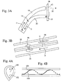
- Fig. 3A shows a side view onto a further embodiment of a spray unit having a steam nozzle 62 and a draining opening 90.
- the steam nozzle 62 is connected to the steam hose 18 and the draining opening 90 is connected to the drain hose 20 shown in Fig. 1 .
- Steam is coming in the upstream direction U from steam generator 14, and drain hose 20 connects in a downstream direction D to condensate reservoir 22.
- a capillary groove (not shown) connects the rim of the steam nozzle opening to the draining opening 90.
- the injected steam is indicated by arrow 92, while the bent arrow shows the draining of the condensed fluid into the drain hose 20.
- FIG. 3B shows in more detail a cross-section through hoses 18 and 20 where a droplet 96 can be seen which passes through via 94 into the drain hose 20.
- Fig. 4A shows another embodiment of a supply hose 100 used for example as the steam hose 18 shown in Fig. 1 .
- a draining edge 102 is provided which runs along the hose's length.
- the draining edge 102 reduces the surface tension energy of droplets, such that the droplets distribute or deliquesce along the edge, and the draining of the fluid is improved thereby.
- Fig. 4B shows another embodiment of a supply hose 106 having improved draining properties by providing a spiral element 108 running along the interior of the supply hose 106.
- a capillary effect is again provided between the inner surface of the hose and the spiral element 108, such that condensate drains off along the spiral element without forming larger diameter droplets.
Landscapes
- Engineering & Computer Science (AREA)
- Textile Engineering (AREA)
- Treatment Of Fiber Materials (AREA)
- Accessory Of Washing/Drying Machine, Commercial Washing/Drying Machine, Other Washing/Drying Machine (AREA)
- Detail Structures Of Washing Machines And Dryers (AREA)
Priority Applications (1)
| Application Number | Priority Date | Filing Date | Title |
|---|---|---|---|
| EP10181585.0A EP2290149B1 (fr) | 2006-11-15 | 2006-11-15 | Injecteur et dispositif d'alimentation d'un additif pour un appareil de traitement de textiles |
Applications Claiming Priority (2)
| Application Number | Priority Date | Filing Date | Title |
|---|---|---|---|
| EP06023712.0A EP1923499B1 (fr) | 2006-11-15 | 2006-11-15 | Injecteur et dispositif d'alimentation d'un additif pour un appareil de traitement de textiles |
| EP10181585.0A EP2290149B1 (fr) | 2006-11-15 | 2006-11-15 | Injecteur et dispositif d'alimentation d'un additif pour un appareil de traitement de textiles |
Related Parent Applications (3)
| Application Number | Title | Priority Date | Filing Date |
|---|---|---|---|
| EP06023712.0A Division-Into EP1923499B1 (fr) | 2006-11-15 | 2006-11-15 | Injecteur et dispositif d'alimentation d'un additif pour un appareil de traitement de textiles |
| EP06023712.0A Division EP1923499B1 (fr) | 2006-11-15 | 2006-11-15 | Injecteur et dispositif d'alimentation d'un additif pour un appareil de traitement de textiles |
| EP06023712.0 Division | 2006-11-15 |
Publications (2)
| Publication Number | Publication Date |
|---|---|
| EP2290149A1 true EP2290149A1 (fr) | 2011-03-02 |
| EP2290149B1 EP2290149B1 (fr) | 2019-04-03 |
Family
ID=37895847
Family Applications (2)
| Application Number | Title | Priority Date | Filing Date |
|---|---|---|---|
| EP10181585.0A Not-in-force EP2290149B1 (fr) | 2006-11-15 | 2006-11-15 | Injecteur et dispositif d'alimentation d'un additif pour un appareil de traitement de textiles |
| EP06023712.0A Not-in-force EP1923499B1 (fr) | 2006-11-15 | 2006-11-15 | Injecteur et dispositif d'alimentation d'un additif pour un appareil de traitement de textiles |
Family Applications After (1)
| Application Number | Title | Priority Date | Filing Date |
|---|---|---|---|
| EP06023712.0A Not-in-force EP1923499B1 (fr) | 2006-11-15 | 2006-11-15 | Injecteur et dispositif d'alimentation d'un additif pour un appareil de traitement de textiles |
Country Status (7)
| Country | Link |
|---|---|
| US (1) | US8819959B2 (fr) |
| EP (2) | EP2290149B1 (fr) |
| CN (1) | CN101535552B (fr) |
| BR (1) | BRPI0718753A2 (fr) |
| MX (1) | MX2009004652A (fr) |
| RU (1) | RU2456391C2 (fr) |
| WO (1) | WO2008058645A1 (fr) |
Cited By (1)
| Publication number | Priority date | Publication date | Assignee | Title |
|---|---|---|---|---|
| WO2021043520A1 (fr) * | 2019-09-04 | 2021-03-11 | Henkel Ag & Co. Kgaa | Fixation et élément fonctionnel pour un générateur de vapeur pour le traitement d'un vêtement |
Families Citing this family (22)
| Publication number | Priority date | Publication date | Assignee | Title |
|---|---|---|---|---|
| KR101366273B1 (ko) * | 2007-08-03 | 2014-02-20 | 엘지전자 주식회사 | 의류처리장치 |
| EP2055824B1 (fr) * | 2007-11-02 | 2014-07-30 | LG Electronics Inc. | Appareil de séchage |
| EP2163682B1 (fr) | 2008-09-12 | 2013-01-09 | Electrolux Home Products Corporation N.V. | Séchoir à linge pour usage domestique |
| IT1394620B1 (it) * | 2008-12-23 | 2012-07-05 | Indesit Co Spa | Metodo per profumare panni in una macchina per il trattamento di panni |
| US8974546B2 (en) * | 2010-02-26 | 2015-03-10 | Whirlpool Corporation | Method for treating laundry in a clothes dryer |
| US8844156B2 (en) | 2010-12-14 | 2014-09-30 | Whirlpool Corporation | Laundry treating appliance with purged chemistry conduits |
| CN102495185A (zh) * | 2011-12-22 | 2012-06-13 | 吴江市德佐日用化学品有限公司 | 一种洗涤试验机 |
| EP2610404A1 (fr) * | 2011-12-27 | 2013-07-03 | Koninklijke Philips Electronics N.V. | Presseur de vêtements à la vapeur |
| KR101959308B1 (ko) * | 2012-09-04 | 2019-07-04 | 엘지전자 주식회사 | 세탁물 처리방법 |
| KR102119538B1 (ko) * | 2013-04-03 | 2020-06-08 | 삼성전자주식회사 | 의류건조기 |
| CN105229218B (zh) * | 2013-05-24 | 2019-04-05 | 伊莱克斯家用电器股份公司 | 衣物干燥机和用于运行衣物干燥机的方法 |
| CN106149329B (zh) * | 2015-03-25 | 2019-11-15 | 青岛海尔洗衣机有限公司 | 干衣机用冷凝水收集蒸发装置、干衣机及其控制方法 |
| DE102015209287B3 (de) * | 2015-05-21 | 2016-07-28 | BSH Hausgeräte GmbH | Wäschepflegegerät mit einer Laugenpumpe |
| CN106609453B (zh) * | 2015-10-22 | 2019-05-21 | 无锡小天鹅股份有限公司 | 用于干衣机的冷凝水盒和具有其的干衣机 |
| DE102016216737B4 (de) * | 2016-09-05 | 2018-03-15 | BSH Hausgeräte GmbH | Wäschepflegegerät mit einer Steuerung |
| DE102017104284A1 (de) * | 2017-03-01 | 2018-05-03 | Miele & Cie. Kg | Textiltrocknungseinheit und Verfahren zum Betreiben einer Textiltrocknungseinheit |
| US10294604B2 (en) * | 2017-06-22 | 2019-05-21 | Haier Us Appliance Solutions, Inc. | Dryer appliance and additive dispensing assembly |
| FR3072102B1 (fr) | 2017-10-05 | 2020-07-31 | Seb Sa | Tete de defroissage comprenant une chambre interne pourvue de canaux d'expulsion de vapeur |
| US11293131B2 (en) | 2018-03-30 | 2022-04-05 | Midea Group Co., Ltd. | Appliance with hand held steam accessory |
| KR102848021B1 (ko) * | 2020-04-21 | 2025-08-21 | 엘지전자 주식회사 | 세탁물 건조기 |
| US12467180B2 (en) | 2021-11-11 | 2025-11-11 | Whirlpool Corporation | Foreign particulate removal assembly |
| US12486611B2 (en) | 2022-04-05 | 2025-12-02 | Haier Us Appliance Solutions, Inc. | Dryer appliance and dispensing system |
Citations (3)
| Publication number | Priority date | Publication date | Assignee | Title |
|---|---|---|---|---|
| US4111645A (en) * | 1972-01-21 | 1978-09-05 | Ciba-Geigy Ag | Fine particle application of dyes or optical brightener to leathers or fabrics in a tumbling drum at low volumes in a hydrophobic solvent |
| WO2003089710A1 (fr) * | 2002-04-22 | 2003-10-30 | The Procter & Gamble Company | Procede et appareil de traitement d'un article textile |
| EP1441060A1 (fr) | 2003-01-25 | 2004-07-28 | Electrolux Home Products Corporation N.V. | Sèche-linge avec un dispositif de pulvérisation des additifs et proédé pour ceci |
Family Cites Families (19)
| Publication number | Priority date | Publication date | Assignee | Title |
|---|---|---|---|---|
| GB1250480A (fr) * | 1968-11-25 | 1971-10-20 | ||
| US3816070A (en) * | 1968-12-31 | 1974-06-11 | R Candor | Method and apparatus for treating porous material with fluid |
| US3739496A (en) * | 1971-03-24 | 1973-06-19 | Mc Graw Edison Co | Steam air cabinet finisher |
| US4207683A (en) * | 1979-02-01 | 1980-06-17 | Horton Roberta J | Clothes dryer |
| DE3408136A1 (de) * | 1984-03-06 | 1985-09-19 | Passat-Maschinenbau Gmbh, 7100 Heilbronn | Verfahren und vorrichtung zum behandeln von textilien |
| SU1430427A1 (ru) * | 1986-11-20 | 1988-10-15 | Алитусский Машиностроительный Завод | Устройство дл подачи моющих средств в стиральную машину |
| US4739698A (en) * | 1987-04-14 | 1988-04-26 | Allaire Pascal M | Apparatus and method for cooking with steam |
| AT390975B (de) * | 1987-06-15 | 1990-07-25 | Andritz Ag Maschf | Vorrichtung mit einer mit einem waermetraegermedium beheizten arbeitsflaeche |
| US5060686A (en) * | 1989-12-27 | 1991-10-29 | Engineering Resources, Inc. | Multi-piece nozzle for steam condensate removal devices |
| CN2069971U (zh) * | 1990-06-22 | 1991-01-23 | 陈小松 | 双筒凝聚湿式旋风除尘器 |
| DE4032490C1 (en) * | 1990-10-12 | 1992-01-30 | Palux Gmbh, 6990 Bad Mergentheim, De | Seal on door frame - acts as condensate trap when door on kitchen steamer is open |
| US5219371A (en) * | 1992-03-27 | 1993-06-15 | Shim Kyong S | Dry cleaning system and method having steam injection |
| IT1289292B1 (it) * | 1996-05-31 | 1998-10-02 | A R M I S R L | Perfezionamenti ad un metodo e ad una apparecchiatura per l'imbrigliamento in corso di tessitura di porzioni terminali di filo |
| JP3893851B2 (ja) * | 1999-10-28 | 2007-03-14 | 松下電工株式会社 | スチーム式美容器 |
| US20090169342A1 (en) * | 2004-06-21 | 2009-07-02 | Takehiko Yoshimura | Load port |
| DE102004057110B9 (de) * | 2004-11-26 | 2008-04-30 | Andreas Stihl Ag & Co. Kg | Abgasanlage eines durch einen Verbrennungsmotor angetriebenen Arbeitsgerätes |
| KR20060061974A (ko) * | 2004-12-02 | 2006-06-09 | 삼성전자주식회사 | 의류의 구김제거장치 및 그 방법 |
| US9663894B2 (en) * | 2005-11-10 | 2017-05-30 | Lg Electronics Inc. | Steam generator and laundry dryer having the same and controlling method thereof |
| KR101220579B1 (ko) * | 2006-05-15 | 2013-01-10 | 엘지전자 주식회사 | 의류 재생 장치 |
-
2006
- 2006-11-15 EP EP10181585.0A patent/EP2290149B1/fr not_active Not-in-force
- 2006-11-15 EP EP06023712.0A patent/EP1923499B1/fr not_active Not-in-force
-
2007
- 2007-11-05 CN CN2007800419352A patent/CN101535552B/zh not_active Expired - Fee Related
- 2007-11-05 WO PCT/EP2007/009548 patent/WO2008058645A1/fr not_active Ceased
- 2007-11-05 BR BRPI0718753-0A2A patent/BRPI0718753A2/pt not_active Application Discontinuation
- 2007-11-05 MX MX2009004652A patent/MX2009004652A/es unknown
- 2007-11-05 RU RU2009122382/12A patent/RU2456391C2/ru not_active IP Right Cessation
- 2007-11-05 US US12/513,610 patent/US8819959B2/en active Active
Patent Citations (3)
| Publication number | Priority date | Publication date | Assignee | Title |
|---|---|---|---|---|
| US4111645A (en) * | 1972-01-21 | 1978-09-05 | Ciba-Geigy Ag | Fine particle application of dyes or optical brightener to leathers or fabrics in a tumbling drum at low volumes in a hydrophobic solvent |
| WO2003089710A1 (fr) * | 2002-04-22 | 2003-10-30 | The Procter & Gamble Company | Procede et appareil de traitement d'un article textile |
| EP1441060A1 (fr) | 2003-01-25 | 2004-07-28 | Electrolux Home Products Corporation N.V. | Sèche-linge avec un dispositif de pulvérisation des additifs et proédé pour ceci |
Cited By (1)
| Publication number | Priority date | Publication date | Assignee | Title |
|---|---|---|---|---|
| WO2021043520A1 (fr) * | 2019-09-04 | 2021-03-11 | Henkel Ag & Co. Kgaa | Fixation et élément fonctionnel pour un générateur de vapeur pour le traitement d'un vêtement |
Also Published As
| Publication number | Publication date |
|---|---|
| RU2009122382A (ru) | 2010-12-20 |
| CN101535552B (zh) | 2013-09-25 |
| BRPI0718753A2 (pt) | 2013-12-03 |
| EP1923499A1 (fr) | 2008-05-21 |
| MX2009004652A (es) | 2009-05-21 |
| US8819959B2 (en) | 2014-09-02 |
| US20100083532A1 (en) | 2010-04-08 |
| RU2456391C2 (ru) | 2012-07-20 |
| EP1923499B1 (fr) | 2018-02-28 |
| EP2290149B1 (fr) | 2019-04-03 |
| CN101535552A (zh) | 2009-09-16 |
| WO2008058645A1 (fr) | 2008-05-22 |
Similar Documents
| Publication | Publication Date | Title |
|---|---|---|
| US8819959B2 (en) | Nozzle and additive supply arrangement for a textiles treatment apparatus | |
| US11214914B2 (en) | Appliances with sudsing-reducing flushable detergent dispensers | |
| US9885143B2 (en) | Laundry drying device and method for cleaning a filter | |
| CN111727284B (zh) | 配备有液体供应管线的洗衣机 | |
| EP2628846B1 (fr) | Appareil de traitement du linge avec nettoyage d'échangeur de chaleur | |
| CN107075776B (zh) | 具有蒸气供应的衣物洗涤设备 | |
| JP7269703B2 (ja) | 洗濯乾燥機 | |
| EA018893B1 (ru) | Бытовой прибор для обработки белья с парогенератором | |
| CN104619903B (zh) | 洗衣机 | |
| KR20140115301A (ko) | 세탁물을 보호하기 위한 가전제품용 린싱 장치, 및 세탁물을 보호하기 위한 가전제품 | |
| EP2766518B1 (fr) | Appareil ménager à circulation d'eau comportant un dispositif de nébulisation ainsi que procédé pour son fonctionnement | |
| KR20170139804A (ko) | 식기 세척기의 제어방법 | |
| KR102578442B1 (ko) | 스팀발생장치 및 스팀발생장치가 구비된 의류처리장치 | |
| EP2628843B1 (fr) | Appareil de traitement du linge avec nettoyage d'échangeur de chaleur | |
| RU2676605C2 (ru) | Прибор для ухода за бельем с отклоняющим элементом | |
| EP2620539A1 (fr) | Appareil de traitement du linge | |
| CN105593426B (zh) | 包括清洁剂分配器的清洗机 | |
| KR20140100072A (ko) | 식기세척기 | |
| CN112144247B (zh) | 用于处理洗涤物的家用器具 | |
| CN108927361A (zh) | 清洗器 | |
| JP7012938B2 (ja) | 洗浄器 | |
| JP2020110764A (ja) | 洗浄器 |
Legal Events
| Date | Code | Title | Description |
|---|---|---|---|
| PUAI | Public reference made under article 153(3) epc to a published international application that has entered the european phase |
Free format text: ORIGINAL CODE: 0009012 |
|
| AC | Divisional application: reference to earlier application |
Ref document number: 1923499 Country of ref document: EP Kind code of ref document: P |
|
| AK | Designated contracting states |
Kind code of ref document: A1 Designated state(s): AT BE BG CH CY CZ DE DK EE ES FI FR GB GR HU IE IS IT LI LT LU LV MC NL PL PT RO SE SI SK TR |
|
| RAP1 | Party data changed (applicant data changed or rights of an application transferred) |
Owner name: ELECTROLUX HOME PRODUCTS CORPORATION N.V. |
|
| RAP1 | Party data changed (applicant data changed or rights of an application transferred) |
Owner name: ELECTROLUX HOME PRODUCTS CORPORATION N.V. |
|
| 17P | Request for examination filed |
Effective date: 20110902 |
|
| STAA | Information on the status of an ep patent application or granted ep patent |
Free format text: STATUS: EXAMINATION IS IN PROGRESS |
|
| 17Q | First examination report despatched |
Effective date: 20170725 |
|
| RIC1 | Information provided on ipc code assigned before grant |
Ipc: D06F 73/02 20060101ALN20180913BHEP Ipc: D06F 39/02 20060101AFI20180913BHEP Ipc: D06F 39/08 20060101ALN20180913BHEP Ipc: D06F 58/20 20060101ALN20180913BHEP |
|
| GRAP | Despatch of communication of intention to grant a patent |
Free format text: ORIGINAL CODE: EPIDOSNIGR1 |
|
| STAA | Information on the status of an ep patent application or granted ep patent |
Free format text: STATUS: GRANT OF PATENT IS INTENDED |
|
| INTG | Intention to grant announced |
Effective date: 20181109 |
|
| RIN1 | Information on inventor provided before grant (corrected) |
Inventor name: ARREGHINI, LUIGI Inventor name: SIERL, JOHANNES Inventor name: LOY, THOMAS Inventor name: KLUG, HANS-JOACHIM |
|
| GRAS | Grant fee paid |
Free format text: ORIGINAL CODE: EPIDOSNIGR3 |
|
| GRAA | (expected) grant |
Free format text: ORIGINAL CODE: 0009210 |
|
| STAA | Information on the status of an ep patent application or granted ep patent |
Free format text: STATUS: THE PATENT HAS BEEN GRANTED |
|
| AC | Divisional application: reference to earlier application |
Ref document number: 1923499 Country of ref document: EP Kind code of ref document: P |
|
| AK | Designated contracting states |
Kind code of ref document: B1 Designated state(s): AT BE BG CH CY CZ DE DK EE ES FI FR GB GR HU IE IS IT LI LT LU LV MC NL PL PT RO SE SI SK TR |
|
| REG | Reference to a national code |
Ref country code: GB Ref legal event code: FG4D |
|
| REG | Reference to a national code |
Ref country code: CH Ref legal event code: EP Ref country code: AT Ref legal event code: REF Ref document number: 1115880 Country of ref document: AT Kind code of ref document: T Effective date: 20190415 |
|
| REG | Reference to a national code |
Ref country code: DE Ref legal event code: R096 Ref document number: 602006057736 Country of ref document: DE |
|
| REG | Reference to a national code |
Ref country code: IE Ref legal event code: FG4D |
|
| REG | Reference to a national code |
Ref country code: NL Ref legal event code: MP Effective date: 20190403 |
|
| REG | Reference to a national code |
Ref country code: LT Ref legal event code: MG4D |
|
| REG | Reference to a national code |
Ref country code: AT Ref legal event code: MK05 Ref document number: 1115880 Country of ref document: AT Kind code of ref document: T Effective date: 20190403 |
|
| PG25 | Lapsed in a contracting state [announced via postgrant information from national office to epo] |
Ref country code: NL Free format text: LAPSE BECAUSE OF FAILURE TO SUBMIT A TRANSLATION OF THE DESCRIPTION OR TO PAY THE FEE WITHIN THE PRESCRIBED TIME-LIMIT Effective date: 20190403 |
|
| PG25 | Lapsed in a contracting state [announced via postgrant information from national office to epo] |
Ref country code: LT Free format text: LAPSE BECAUSE OF FAILURE TO SUBMIT A TRANSLATION OF THE DESCRIPTION OR TO PAY THE FEE WITHIN THE PRESCRIBED TIME-LIMIT Effective date: 20190403 Ref country code: SE Free format text: LAPSE BECAUSE OF FAILURE TO SUBMIT A TRANSLATION OF THE DESCRIPTION OR TO PAY THE FEE WITHIN THE PRESCRIBED TIME-LIMIT Effective date: 20190403 Ref country code: PT Free format text: LAPSE BECAUSE OF FAILURE TO SUBMIT A TRANSLATION OF THE DESCRIPTION OR TO PAY THE FEE WITHIN THE PRESCRIBED TIME-LIMIT Effective date: 20190803 Ref country code: ES Free format text: LAPSE BECAUSE OF FAILURE TO SUBMIT A TRANSLATION OF THE DESCRIPTION OR TO PAY THE FEE WITHIN THE PRESCRIBED TIME-LIMIT Effective date: 20190403 Ref country code: CZ Free format text: LAPSE BECAUSE OF FAILURE TO SUBMIT A TRANSLATION OF THE DESCRIPTION OR TO PAY THE FEE WITHIN THE PRESCRIBED TIME-LIMIT Effective date: 20190403 Ref country code: FI Free format text: LAPSE BECAUSE OF FAILURE TO SUBMIT A TRANSLATION OF THE DESCRIPTION OR TO PAY THE FEE WITHIN THE PRESCRIBED TIME-LIMIT Effective date: 20190403 |
|
| PG25 | Lapsed in a contracting state [announced via postgrant information from national office to epo] |
Ref country code: GR Free format text: LAPSE BECAUSE OF FAILURE TO SUBMIT A TRANSLATION OF THE DESCRIPTION OR TO PAY THE FEE WITHIN THE PRESCRIBED TIME-LIMIT Effective date: 20190704 Ref country code: BG Free format text: LAPSE BECAUSE OF FAILURE TO SUBMIT A TRANSLATION OF THE DESCRIPTION OR TO PAY THE FEE WITHIN THE PRESCRIBED TIME-LIMIT Effective date: 20190703 Ref country code: PL Free format text: LAPSE BECAUSE OF FAILURE TO SUBMIT A TRANSLATION OF THE DESCRIPTION OR TO PAY THE FEE WITHIN THE PRESCRIBED TIME-LIMIT Effective date: 20190403 Ref country code: LV Free format text: LAPSE BECAUSE OF FAILURE TO SUBMIT A TRANSLATION OF THE DESCRIPTION OR TO PAY THE FEE WITHIN THE PRESCRIBED TIME-LIMIT Effective date: 20190403 |
|
| PG25 | Lapsed in a contracting state [announced via postgrant information from national office to epo] |
Ref country code: IS Free format text: LAPSE BECAUSE OF FAILURE TO SUBMIT A TRANSLATION OF THE DESCRIPTION OR TO PAY THE FEE WITHIN THE PRESCRIBED TIME-LIMIT Effective date: 20190803 Ref country code: AT Free format text: LAPSE BECAUSE OF FAILURE TO SUBMIT A TRANSLATION OF THE DESCRIPTION OR TO PAY THE FEE WITHIN THE PRESCRIBED TIME-LIMIT Effective date: 20190403 |
|
| REG | Reference to a national code |
Ref country code: DE Ref legal event code: R097 Ref document number: 602006057736 Country of ref document: DE |
|
| PG25 | Lapsed in a contracting state [announced via postgrant information from national office to epo] |
Ref country code: EE Free format text: LAPSE BECAUSE OF FAILURE TO SUBMIT A TRANSLATION OF THE DESCRIPTION OR TO PAY THE FEE WITHIN THE PRESCRIBED TIME-LIMIT Effective date: 20190403 Ref country code: DK Free format text: LAPSE BECAUSE OF FAILURE TO SUBMIT A TRANSLATION OF THE DESCRIPTION OR TO PAY THE FEE WITHIN THE PRESCRIBED TIME-LIMIT Effective date: 20190403 Ref country code: SK Free format text: LAPSE BECAUSE OF FAILURE TO SUBMIT A TRANSLATION OF THE DESCRIPTION OR TO PAY THE FEE WITHIN THE PRESCRIBED TIME-LIMIT Effective date: 20190403 Ref country code: RO Free format text: LAPSE BECAUSE OF FAILURE TO SUBMIT A TRANSLATION OF THE DESCRIPTION OR TO PAY THE FEE WITHIN THE PRESCRIBED TIME-LIMIT Effective date: 20190403 |
|
| PLBE | No opposition filed within time limit |
Free format text: ORIGINAL CODE: 0009261 |
|
| STAA | Information on the status of an ep patent application or granted ep patent |
Free format text: STATUS: NO OPPOSITION FILED WITHIN TIME LIMIT |
|
| 26N | No opposition filed |
Effective date: 20200106 |
|
| PG25 | Lapsed in a contracting state [announced via postgrant information from national office to epo] |
Ref country code: TR Free format text: LAPSE BECAUSE OF FAILURE TO SUBMIT A TRANSLATION OF THE DESCRIPTION OR TO PAY THE FEE WITHIN THE PRESCRIBED TIME-LIMIT Effective date: 20190403 |
|
| PG25 | Lapsed in a contracting state [announced via postgrant information from national office to epo] |
Ref country code: SI Free format text: LAPSE BECAUSE OF FAILURE TO SUBMIT A TRANSLATION OF THE DESCRIPTION OR TO PAY THE FEE WITHIN THE PRESCRIBED TIME-LIMIT Effective date: 20190403 |
|
| REG | Reference to a national code |
Ref country code: CH Ref legal event code: PL |
|
| PG25 | Lapsed in a contracting state [announced via postgrant information from national office to epo] |
Ref country code: CH Free format text: LAPSE BECAUSE OF NON-PAYMENT OF DUE FEES Effective date: 20191130 Ref country code: MC Free format text: LAPSE BECAUSE OF FAILURE TO SUBMIT A TRANSLATION OF THE DESCRIPTION OR TO PAY THE FEE WITHIN THE PRESCRIBED TIME-LIMIT Effective date: 20190403 Ref country code: LU Free format text: LAPSE BECAUSE OF NON-PAYMENT OF DUE FEES Effective date: 20191115 Ref country code: LI Free format text: LAPSE BECAUSE OF NON-PAYMENT OF DUE FEES Effective date: 20191130 |
|
| REG | Reference to a national code |
Ref country code: BE Ref legal event code: MM Effective date: 20191130 |
|
| GBPC | Gb: european patent ceased through non-payment of renewal fee |
Effective date: 20191115 |
|
| PG25 | Lapsed in a contracting state [announced via postgrant information from national office to epo] |
Ref country code: GB Free format text: LAPSE BECAUSE OF NON-PAYMENT OF DUE FEES Effective date: 20191115 Ref country code: FR Free format text: LAPSE BECAUSE OF NON-PAYMENT OF DUE FEES Effective date: 20191130 Ref country code: IE Free format text: LAPSE BECAUSE OF NON-PAYMENT OF DUE FEES Effective date: 20191115 |
|
| PG25 | Lapsed in a contracting state [announced via postgrant information from national office to epo] |
Ref country code: BE Free format text: LAPSE BECAUSE OF NON-PAYMENT OF DUE FEES Effective date: 20191130 |
|
| PGFP | Annual fee paid to national office [announced via postgrant information from national office to epo] |
Ref country code: DE Payment date: 20201119 Year of fee payment: 15 Ref country code: IT Payment date: 20201124 Year of fee payment: 15 |
|
| PG25 | Lapsed in a contracting state [announced via postgrant information from national office to epo] |
Ref country code: CY Free format text: LAPSE BECAUSE OF FAILURE TO SUBMIT A TRANSLATION OF THE DESCRIPTION OR TO PAY THE FEE WITHIN THE PRESCRIBED TIME-LIMIT Effective date: 20190403 |
|
| PG25 | Lapsed in a contracting state [announced via postgrant information from national office to epo] |
Ref country code: HU Free format text: LAPSE BECAUSE OF FAILURE TO SUBMIT A TRANSLATION OF THE DESCRIPTION OR TO PAY THE FEE WITHIN THE PRESCRIBED TIME-LIMIT; INVALID AB INITIO Effective date: 20061115 |
|
| REG | Reference to a national code |
Ref country code: DE Ref legal event code: R119 Ref document number: 602006057736 Country of ref document: DE |
|
| PG25 | Lapsed in a contracting state [announced via postgrant information from national office to epo] |
Ref country code: DE Free format text: LAPSE BECAUSE OF NON-PAYMENT OF DUE FEES Effective date: 20220601 |
|
| PG25 | Lapsed in a contracting state [announced via postgrant information from national office to epo] |
Ref country code: IT Free format text: LAPSE BECAUSE OF NON-PAYMENT OF DUE FEES Effective date: 20211115 |