EP2290159A2 - Méthode pour extraire des fibres d'un mélange comprenant des fibres - Google Patents
Méthode pour extraire des fibres d'un mélange comprenant des fibres Download PDFInfo
- Publication number
- EP2290159A2 EP2290159A2 EP10011002A EP10011002A EP2290159A2 EP 2290159 A2 EP2290159 A2 EP 2290159A2 EP 10011002 A EP10011002 A EP 10011002A EP 10011002 A EP10011002 A EP 10011002A EP 2290159 A2 EP2290159 A2 EP 2290159A2
- Authority
- EP
- European Patent Office
- Prior art keywords
- pulper
- fibers
- mixture
- screw
- pulp
- Prior art date
- Legal status (The legal status is an assumption and is not a legal conclusion. Google has not performed a legal analysis and makes no representation as to the accuracy of the status listed.)
- Withdrawn
Links
Images


Classifications
-
- D—TEXTILES; PAPER
- D21—PAPER-MAKING; PRODUCTION OF CELLULOSE
- D21B—FIBROUS RAW MATERIALS OR THEIR MECHANICAL TREATMENT
- D21B1/00—Fibrous raw materials or their mechanical treatment
- D21B1/04—Fibrous raw materials or their mechanical treatment by dividing raw materials into small particles, e.g. fibres
- D21B1/12—Fibrous raw materials or their mechanical treatment by dividing raw materials into small particles, e.g. fibres by wet methods, by the use of steam
- D21B1/30—Defibrating by other means
- D21B1/34—Kneading or mixing; Pulpers
- D21B1/345—Pulpers
- D21B1/347—Rotor assemblies
-
- Y—GENERAL TAGGING OF NEW TECHNOLOGICAL DEVELOPMENTS; GENERAL TAGGING OF CROSS-SECTIONAL TECHNOLOGIES SPANNING OVER SEVERAL SECTIONS OF THE IPC; TECHNICAL SUBJECTS COVERED BY FORMER USPC CROSS-REFERENCE ART COLLECTIONS [XRACs] AND DIGESTS
- Y02—TECHNOLOGIES OR APPLICATIONS FOR MITIGATION OR ADAPTATION AGAINST CLIMATE CHANGE
- Y02W—CLIMATE CHANGE MITIGATION TECHNOLOGIES RELATED TO WASTEWATER TREATMENT OR WASTE MANAGEMENT
- Y02W30/00—Technologies for solid waste management
- Y02W30/50—Reuse, recycling or recovery technologies
- Y02W30/64—Paper recycling
Definitions
- the invention relates to a method for obtaining fibers from a mixture containing fibers, in which the mixture is fed to a pulper with a pulp discharge.
- the invention proposes a method for recovering fibers from a mixture containing fibers, in which the mixture is fed to a pulper with a pulp discharge and which is characterized in that the free fiber content in the pulper under 80% or that the proportion of pieces in pulper is over 20%.
- the materials to be separated are fibrous materials or conglomerates of fibrous materials, such as, for example, specks, paper shreds, wallpapers, labels or the like, which occur together with other accompanying substances.
- fibrous materials or conglomerates of fibrous materials such as, for example, specks, paper shreds, wallpapers, labels or the like.
- the method described is able to solve even solid connections between the accompanying substances and the fibrous materials.
- it is suitable, for example, for separating composite materials or labels in which plastic components, such as, for example, films, fiber-containing layers and adhesives or adhesive layers and also fibers, for example in the form of paper, are connected to one another.
- fibers can be dissolved out of such materials, these fibers can be present both in the fiber composite, such as specks, as well as individual fibers.
- the term "adhere” is accordingly explained that this is understood to mean a connection between accompanying substances and fibers or fibrous materials, which goes beyond a mere juxtaposition in the fibers and the accompanying substances, wherein, of course, individual fibers or specks, which are only adjacent Accompanying substances may be present in the mixture to be separated from fibrous materials and accompanying substances.
- the term "piece” generally describes constituents of the pulper abandoned mixture, which can not pass through the separator, as this snippet, schnitzel or specks or represent the accompanying substances. During the residence time in the pulper, these pieces of material can dissolve completely when an impurity-free mixture has been given to the pulper. Otherwise, accompanying substances with or without adhesive fibers adhering to them or only uneconomically to be shredded snippets are present in the pulper, which can then advantageously have an accompanying substance discharge.
- the above described method is particularly suitable for a pulper with a continuous pulp discharge.
- a simple adjustment or control of the free fiber portion is made possible by the flow rate of the discharge is selected or regulated accordingly.
- the raw materials such as accompanying substances and / or large snippets or the like can be continuously removed from the pulper, so that a relatively long continuous operating time can be achieved, with intermediate downtime, for example, for cleaning to remove sand or the like, not excluded are.
- Such a discontinuous operation of the pulper with respect to the raw materials at the same time continuous pulp discharge makes it possible, regardless of the other features of the present invention, to obtain fibers from a fiber-containing mixture with high efficiency or high throughput.
- the free fiber portions or the proportions of raw materials, the total material density and the ratios of free fibers in the pulper or in the pulp discharge can be set in the desired manner.
- fibers can also be present or present in the output of the product, while certain accompanying substances, which, however, are largely freed from fibers, can be present to a lesser extent in the pulp discharge.
- the throughput through the pulper can be optimized in particular if the free fiber content in the pulper is less than 75% or less than 70%. Accordingly, it is advantageous if the proportion of the raw materials in the pulper is more than 25% or more than 30%.
- the free fiber content in the pulper is less than 10% or the proportion of the raw materials is more than 90%. This allows a particularly good friction or mechanical stress of the raw materials are guaranteed with the adhering to these fibers. Accordingly, it is particularly advantageous if the free fiber content in the pulper is less than 5% or less than 1% or even less than 0.5%, or if the proportion of raw materials is more than 95%, more than 99% or even more than 99.5% , In particular, these low free fiber fractions or high levels of raw materials provide excellent separation performance under extreme conditions, such as in difficult fibers, such as labels, wallpaper or heavy fibreboard waste paper, although it was not to be expected that at such low free fiber fractions effective separation processes take place can.
- large pulp agglomerates or very large solid constituents of the mixture charged to the pulper such as, for example, whole wallpaper rolls or waste paper bales, are not included in the present calculations, but are taken into account only when the work of the pulper has disrupted these agglomerates in chip size If appropriate, decay curves for such agglomerates can be ascertained and taken into account in addition, if this is considered necessary with regard to the accuracy of the operating point of the pulper.
- the free-fiber density in the pulp discharge namely the volume fraction of free fibers based on the total volume of free fibers and water or dispersion medium in the pulp discharge is chosen below 3%.
- Such a free fiber density can also be adjusted by a suitable choice of the boundary conditions, such as the screen and the movement in the pulper or by the choice of the water flow rate in the desired manner. It is particularly advantageous if the free-fiber density is less than 2%, less than 1% or even far below, in order to ensure a high separation efficiency.
- the total stock density ie, the volume fraction of all pulp in relation to the total volume of these fabrics and the dispersant or water, by at least a factor of 5, preferably 10, greater than the pulp density in the Faserstoffaustrag.
- the free fibers should dwell as short as possible in the pulper in order to achieve a high throughput. This can be ensured in particular by a pulp discharge with high throughput or with a very low free fiber density. It has been found to be advantageous if, in a method for obtaining fibers from a mixture containing fibers, in which the mixture is fed to a pulper with a pulp, the average residence time of the fibers of the pulp in the pulper under 10, preferably 6 or 2 minutes. In this case, the average residence time is determined on the basis of the amount of fibers in the pulper and the discharged amount of free fibers per unit time.
- the suitable choice of the residence time can depend strongly on the materials, so that alternatively, in particular for critical material combinations, as can be found, for example, in labels, the residence time can be determined on the basis of the digestion behavior in a discontinuous separation process.
- the residence time in a batch pulper, it is determined how long it takes for 95% of the pulped fibers contained in the pulper to be present as free fibers.
- the average residence time of the fibers of the fibers of this batch in the pulper is then selected according to the invention in the current process below 50%, preferably below 30% or below 10%, the time for a 95% digestion in discontinuous operation.
- stickies in the pulper itself can be avoided, which form as agglomerates of adhesive contaminants at prolonged residence time in the pulper and then in the arrangements of the prior art can be removed only very bad (secondary stickies).
- second stickies the gentle treatment and, in addition, the short residence time of the mixture given to the pulper prevent the breaking up of the pieces into stickies (primary stickies).
- the average residence time of the free fibers in the pulper is 6 minutes or less.
- the average residence time of the free fibers is determined as the volume of the pulper divided by the volume flow of the dispersant through the pulper, assuming that the free fibers are detected by the volume flow and carried. In this way, a particularly gentle treatment of the free fibers can be ensured in particular. In addition, this can also be achieved a surprising increase in performance, so that the required pumping power surprisingly not increase excessively. Residence times of 3 minutes, in particular 30 seconds or 15 seconds, which, moreover, also minimize the formation of stickies, as described above, are particularly advantageous.
- a method for recovering fibers from a mixture containing fibers in which the mixture is a pulper with a pulp discharge is abandoned and which is characterized by the fact that the average residence time of the free fibers in the pulper is 6 minutes or less.
- an operating temperature between 40 ° C and 90 ° C is present in the pulper.
- an operating temperature between 50 ° C and 85 ° C, preferably between 60 ° C and 80 ° C has proven to be advantageous.
- Such operating temperatures surprisingly lead independently of the other features of the present invention in a gain of fibers from a mixture containing fibers, in which the mixture is fed to a pulper with a pulp, to a much gentler pulping of the fibers, so that the average residence times shortened can be.
- the fibers are not significantly adversely affected.
- the temperatures also damage the accompanying substances, even if these plastics, such as PVC or PE, are not. In particular, it does not come in this context to the expected actual braid or clumping when the plastics are heated and thus stickier and softer.
- the Indian FIG. 1 Pulper 1 shown comprises a pulper body 2 which has a pulper bottom 3, starting from which a successive upwardly initially expanding and then rejuvenating Pulperhauptwandung 4 builds. From a maximum filling level 5 of the pulper 1, the pulper body 2 expands as an entry opening 6. At least the entry of a batch 7 into the pulper 1 takes place via the entry opening 6.
- the Pulperhauptwandung in particular the Pulperinnenwandung 8, tapers concentrically successively starting from a widest range up to the maximum filling height 5 along and about a screw rotation axis 9 of a pulper screw 10.
- the pulper screw 10 is centered within the pulper body 2 and immediately above a Pulpersiebes. 1 arranged.
- both the pulper screw 10 and the Pulpersieb 11 each form a release agent to solve fibers of fibers having constituents of the batch 7 or separate.
- the mixture can be, for example, conglomerates of fibers, such as paper shreds or labels, and / or fiber-free materials, such as foil snippets u. ⁇ ., To which adhere fibers, such as rejects include.
- the pulper 10 has two different work areas, the two mutually different working areas of the pulley screw 10 give different functionalities.
- the pulper screw 10 in its upper region on an axial conveyor 12, which is formed in this embodiment as a worm drive.
- the axial conveyor 12 of the pulper screw 10 the mixture 7 is conveyed from a pre-reaction chamber 14 into a reaction space 15 of the pulper 1 in accordance with an axial main conveying direction 13.
- the axial conveyor 13 passes directly into a radial conveyor 16 of the pulper 10.
- the mixture is conveyed in a radial main conveying direction 17 to the outside, to then be deflected upward. Due to the downward-pointing, due to the axial conveyor 12 flow, the mixture is then accelerated back down, so that a main circulation 19 results.
- the fibers are dissolved particularly effectively, then pass through the Pulpersieb 11 and are conveyed from the pulper 1 via a corresponding Faserstoffaustrag 18 (numbered here only by way of example).
- the reaction space 15 of the present pulper 1 is characterized essentially by the fact that in this area the main circulation 19 of the mixture 7 takes place, in particular also in the vertical direction.
- the pre-reaction chamber 14 is accordingly above the reaction space 15 and is characterized by a lower circulation 20 or only a substantially horizontal circulation of the mixture 7 from.
- the pre-reaction space 14 extends from an upper Hauptumicalzsky 21 to the maximum filling level 5 of the pulper 1.
- the reaction space 15 extends from the upper Hauptumicalzgrenze 21 to a lower Hauptumskylzsky 22, which is in this case formed by the Pulpersieb 11.
- the small circulation 20 in the pre-reaction chamber 14 is mainly due to the fact that one end 23 of the pulper screw 10 projects into the pre-reaction space 14 and from there the mixture accelerates downwards so that the main circulation 19 can not reach the pre-reaction space 14. Through the screw end 23 and the main circulation 19, the small circulation 20 in the pre-reaction chamber 14 is caused.
- the axial conveyor 12 has an axial conveyor diameter 24 and the radial conveyor 16 has a radial conveyor diameter 25, wherein the Axialbanker thoroughlymesser 24 is smaller than the radial conveyor diameter 25.
- the pulper 1 has, at least in the region of the radial conveyor 16, a diameter ratio of Pulperschraubenau built tomesser / Pulperinnen barnmesser, which is greater than 1/3.
- the in the FIG. 2 shown envelope 30 schematically forms the outer contour of in the FIG. 1 shown pulper screw 10 from.
- the envelope 30 in this exemplary embodiment has a radial jacket surface area 31, which in the present case is divided into three subregions 31 A, 31 B and 31 C.
- the envelope 30 has an upper axial lateral surface region 35 and a lower axial lateral surface region 36, which, however, are of secondary interest in the present case.
- the radial mantle surface area 31 has a pitch change 32, which are respectively provided at the transitions between the subregions 31A, 31B and 31C.
- a pitch change 32 which are respectively provided at the transitions between the subregions 31A, 31B and 31C.
- Starting from the lower axial lateral surface area 36 of the radial begins Mantle surface area 31 with the sub-area 31C, which merges into the middle sub-area 31B.
- the middle sub-area 31B then merges into the upper sub-area 31A.
- the Indian FIG. 3 Pulper 101 shown comprises a pulper body 102, which is divisible into three areas.
- the first region is formed by a pulper bottom 103, to which a pulper main wall 104 of the pulper body 102 adjoins.
- the pulp main wall 104 merges into the area of an entry opening 106 of the pulper 101.
- the accompanying substance discharge 140 has a discharge pipe 141, in which a discharge screw 143 driven by a discharge engine 142 rotates. It is understood that instead of the discharge screw 143, for example, a gripper or a conveyor belt can be used as Austragsorgan on Begleitstoffaustrag 140, as this particular in the pulper 1 after FIG. 1 can be provided.
- a pulper screw 110 and a pulp screen 111 are arranged as separating means by which the fibers are separated from the fibers.
- Pulper screw 110 is placed directly above pulley screen 111 and rotates about a screw rotation axis 109.
- Pulper screw 110 has a first working area, which as axial conveyor 112 is a mixture 107 filled in pulper 101 in an axial main conveying direction 113 from inlet opening 106 to pulper bottom 103 promotes.
- the axial conveyor 112 has a Axial simplifieder thoroughlymesser 124 which is substantially smaller than a radial conveyor diameter 125 of the radial conveyor 116, wherein the envelope curve of the screw of the in FIG. 2 corresponds to the envelope shown.
- the fibers released in the pulper pass through the pulp screen 111 into a pulp discharge 118 and are thus removed from the pulper 101.
- the separation of the fibers from the batch 107 is in this embodiment compared to in FIG. 1 illustrated embodiment further improved by the Pulperinnenwandung 108 is formed such that it is adapted to the contour of the pulper screw 110 and follow it.
- the Pulperinnenwandung 108 two mutually different pitch changes, see in particular 144 and 145, wherein the change in slope 144, 145 the transition between 31A and 31B in FIG. 2 and the slope change between pulper bottom and 145 the transition between 31B and 31C in FIG FIG. 2 equivalent.
- the pulper 101 has a diameter ratio of screw outer diameter / Pulperinnen pressmesser, which is greater than one third.
- a particularly effective dissolving and separating the fibers is achieved by accompanying substances.
- the pellet screw 110 is essentially arranged in a reaction space 115 of the pulper 101 1, so that only one end 123 of the pulp screw 110 projects into a pre-reaction space 114.
- the reaction space 115 in the present case extends from a lower main circulation boundary 122, which is essentially formed by the pulp screen 111, to an upper main circulation boundary 121, which is characterized in that a transition from a main circulation 119 to a lower circulation 120 occurs in this area yields, as shown ready in the previously described embodiment.
- the upper Hauptumicalzinho 121 may move within the pulper 101 along the screw rotation axis 109, as it depends, inter alia, on the processed mixture 107 and / or the rotational speed of the screw screw 110. It is essential, however, that the upper main circulation limit 121 always lies in the region of the pulley screw end 123, so that the end 23 of the pulper screw 110 is located, as far as possible, in the pre-rotation space 114.
- the Indian FIG. 4 The pulper 201 shown has substantially the same structure as the above-described pulper 1 of FIG. 1 , wherein in addition to a pulper body 202, a Begleitstoffaustrag 240 is arranged.
- the accompanying discharge 240 comprises a discharge pipe 241.
- a discharge screw 243 which is driven by means of a discharge motor 242, rotates.
- the accompanying substance discharge 240 is provided in the region of a pulper main wall 204 and ensures a continuous removal of the accompanying substances from the reaction space 215 of the pulper 201.
- the pulper 201 is identical to the pulper 1 from the FIG. 1 and to avoid repetition of the present explanation, further description of the pulper 201 will be omitted.
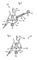
- Pulpers 301, 401 shown each have a driver 310, 410, which is driven by a motor 350, 450.
- the driver 310, 410 sets a batch 307, 407, located in the pulpers 301, 401, of pieces of material, such as accompanying substances and / or specks, and free fibers, thereby ensuring that fibers adhering to the accompanying substances or fibers united to form specks to solve.
- this mixture is conveyed to the pulper 301, 401 in a manner known per se via the batch entry 307, 407, which is only schematically outlined here, through an upper opening 306,406 the pulper 301, 401 abandoned as needed.
- the pulpers 301, 401 have in their lower part 303, 403 (pulper bottom) via a Pulpersieb 311, 411, which serve as a static release agent and are chosen such that, if possible, only dissolved in the water free fibers can penetrate this. It is understood that even minor components of the accompanying substances should such small constituents are present in the pulper 301, 401, the sieves 311, 411 can penetrate, which are then later captured. On the other hand, in this process relatively little such small accompanying substances occur, since the pulper 301, 401 in itself does not destroy the materials placed on it but only separates from one another by mechanical stresses.
- the im FIG. 5 shown pulper 301 also has a separate accompanying discharge 340, which is shown in the present embodiment via a screw 343 which is driven by a motor 342. It is understood that the accompanying substance discharge 340 removes the mixture 307 contained in the pulper 301 from raw materials such as accompanying substances and / or specks and free fibers as well as possibly some water from the pulper 301 and can optionally be operated continuously or discontinuously.
- the output of material is carried out through the entry port 406.
- the batch 407 contained in the pulper 401 is taken from the raw material, such as impurities and / or specks, and free fibers and possibly some water from the pulper 401 on the pulp output.
- the sieves 311, 411 and the drivers 310, 410 are preferably selected such that the pulpers 301, 401 with a free fiber fraction between 0.3% and 1.5% or with a proportion of raw materials between 99.7% and 98.5% can be driven.
- the choice of the throughput in the pulp discharge but also by the choice of the amount of water dispensed, the amount of mixture charged and by the appropriate accompanying discharge and by the choice of Pulpergeometrie beyond the total material density in the pulper 310, 410 selected ten times as high as the pulp density in the underflow 351, 451.
- the free-fiber density in the lower reaches 351, 451 at 1% and below, so that the total material density in the pulper 310, 410 is set at 10%.
- pulpers on which the invention is based are suitable both for continuous, periodic and continuously pulsed use.
- the total material density can be far higher and preferably up to 30%.
- FIGS. 7 and 8th can be determined at given conditions, especially given pulper and given material which is fed to the pulper, the dissolution time and thus the residence time.
- corresponding measurements of the speckle content in discontinuous operation are carried out beforehand, which are shown as examples in the following table for different pulper types (cylinder and disc, cylinder and screw, conical and screw).
- Table 1 ⁇ / b> Shredding time in minutes 0 2 4 6 8th 10 16 20 24 28 32 40 44 60 80 100 Cylinder and disc 93 80 74 65 55 50 23 20 Cylinder and screw 76 55 35 24 15 7 4 2 Conical and screw 71 50 33 23 19 11 6 3 1 0.5
- the production performance can be represented as defibration performance multiplied by the total entry, which is exemplified in Table 3 below.
- Table 3 ⁇ / b> dip 100 93 80 60 40 30 10 5 0 Cylinder and disc 2 2 0.5 0.3 0.2 Cylinder and screw 10 7.5 4.2 0.7 0.2 Conical and screw 14 11 6.2 1.4 0.5
- the performance of the pulper can be specifically increased by the measures according to the claim. Furthermore, it has surprisingly been found that the formation of agglomerates or stickies due to the extremely short residence time in the pulper by the fact that further adhesive or adhesive residues form on the smallest adhesive or adhesive residues, which then become larger and larger, can be avoided. Incidentally, the gentle treatment and, in addition, the short residence time of the mixture given to the pulper prevent the breaking up of the pieces into stickies. It is understood that the conditions in the pulper need not be chosen in the manner described above. Rather, other methods, for example in continuous operation, are conceivable in order to be able to determine and optimize the fiberization times and the pulper outputs.
- an area of the defibration curve appears to have been chosen in which it is particularly steep, ie, the defibration performance for whatever reason is particularly high, thus - contrary to the opinion of all specialists working in this field - a pulper with a very low free fiber content and short residence time of the pulper discontinued mixture to operate, which can be additionally complementary advantages, such as an extremely gentle treatment of the discontinued mixture and avoiding the formation of stickies, with a suitable choice of parameters can be achieved overall.
Landscapes
- Engineering & Computer Science (AREA)
- Life Sciences & Earth Sciences (AREA)
- Wood Science & Technology (AREA)
- Mechanical Engineering (AREA)
- Paper (AREA)
Applications Claiming Priority (4)
| Application Number | Priority Date | Filing Date | Title |
|---|---|---|---|
| DE102005023566 | 2005-05-18 | ||
| DE102005023750 | 2005-05-19 | ||
| DE102005045469A DE102005045469A1 (de) | 2005-05-18 | 2005-09-22 | Verfahren zum Gewinnen von Fasern aus einer Fasern enthaltenden Mischung |
| EP06753178.0A EP1882061B1 (fr) | 2005-05-18 | 2006-05-18 | Broyeur pour recycler un melange |
Related Parent Applications (2)
| Application Number | Title | Priority Date | Filing Date |
|---|---|---|---|
| EP06753178.0A Division-Into EP1882061B1 (fr) | 2005-05-18 | 2006-05-18 | Broyeur pour recycler un melange |
| EP06753178.0 Division | 2006-05-18 |
Publications (2)
| Publication Number | Publication Date |
|---|---|
| EP2290159A2 true EP2290159A2 (fr) | 2011-03-02 |
| EP2290159A3 EP2290159A3 (fr) | 2012-07-04 |
Family
ID=37137564
Family Applications (2)
| Application Number | Title | Priority Date | Filing Date |
|---|---|---|---|
| EP10011002A Withdrawn EP2290159A3 (fr) | 2005-05-18 | 2006-05-18 | Méthode pour extraire des fibres d'un mélange comprenant des fibres |
| EP06753178.0A Not-in-force EP1882061B1 (fr) | 2005-05-18 | 2006-05-18 | Broyeur pour recycler un melange |
Family Applications After (1)
| Application Number | Title | Priority Date | Filing Date |
|---|---|---|---|
| EP06753178.0A Not-in-force EP1882061B1 (fr) | 2005-05-18 | 2006-05-18 | Broyeur pour recycler un melange |
Country Status (5)
| Country | Link |
|---|---|
| EP (2) | EP2290159A3 (fr) |
| DE (2) | DE102005045469A1 (fr) |
| ES (1) | ES2531533T3 (fr) |
| PL (1) | PL1882061T3 (fr) |
| WO (1) | WO2006122538A2 (fr) |
Families Citing this family (4)
| Publication number | Priority date | Publication date | Assignee | Title |
|---|---|---|---|---|
| DE102007039744A1 (de) | 2007-04-18 | 2008-10-23 | Repa Boltersdorf Gmbh | Pulper zum Recyceln eines Gemenges |
| DE102009009405A1 (de) * | 2008-08-28 | 2010-03-04 | Repa Boltersdorf Gmbh | Pulper mit einem Siebblech und Verwendung eines derartigen Pulpers |
| DE502009000349D1 (de) * | 2008-08-28 | 2011-03-10 | Hans-Joachim Boltersdorf | Pulper mit einem Siebblech und Verwendungen eines derartigen Pulpers |
| CN102933764A (zh) * | 2010-05-19 | 2013-02-13 | 汉斯-乔基姆·鲍尔特斯多夫 | 带有供应腔和置换腔的制浆机 |
Citations (3)
| Publication number | Priority date | Publication date | Assignee | Title |
|---|---|---|---|---|
| EP0829571A1 (fr) | 1996-09-12 | 1998-03-18 | Hans-Joachim Boltersdorf | Procédé de récupération de fibres et de matière plastiques à partir des rejets de systèmes d'évacuation de mise en pâte |
| DE19833580A1 (de) | 1998-03-27 | 1999-09-30 | Boltersdorf Hans Joachim | Anlage zur Gewinnugn von Faserstoffen und anderen Wertstoffen aus Rejekten |
| EP1275770A2 (fr) | 2001-07-11 | 2003-01-15 | Repa Boltersdorf GmbH | Dispositif de séparation de matières fibreuses et procédé de séparation de matières légères |
Family Cites Families (6)
| Publication number | Priority date | Publication date | Assignee | Title |
|---|---|---|---|---|
| US4593861A (en) * | 1982-08-12 | 1986-06-10 | The Black Clawson Company | Apparatus for pulping paper making stock at high consistencies |
| US4725007A (en) * | 1983-02-28 | 1988-02-16 | The Black Clawson Company | Apparatus for pulping high consistency paper making stock |
| FR2544756B1 (fr) * | 1983-04-22 | 1985-08-30 | Lamort E & M | Perfectionnements aux turbines de defibrage |
| FR2630139A1 (fr) * | 1988-04-18 | 1989-10-20 | Lamort E & M | Pulpeur de pate a papier |
| DE9014491U1 (de) * | 1990-10-19 | 1991-04-18 | Verwaltungs Lohse GmbH & Co KG, 7920 Heidenheim | Stofflöser, insbesondere zum Auflösen von Biomasse |
| US6508422B2 (en) * | 2001-05-11 | 2003-01-21 | Voith Paper, Inc. | Pulper for a fiber stock preparation system |
-
2005
- 2005-09-22 DE DE102005045469A patent/DE102005045469A1/de not_active Withdrawn
-
2006
- 2006-05-18 DE DE112006001463T patent/DE112006001463A5/de not_active Withdrawn
- 2006-05-18 PL PL06753178T patent/PL1882061T3/pl unknown
- 2006-05-18 WO PCT/DE2006/000862 patent/WO2006122538A2/fr not_active Ceased
- 2006-05-18 EP EP10011002A patent/EP2290159A3/fr not_active Withdrawn
- 2006-05-18 ES ES06753178.0T patent/ES2531533T3/es active Active
- 2006-05-18 EP EP06753178.0A patent/EP1882061B1/fr not_active Not-in-force
Patent Citations (3)
| Publication number | Priority date | Publication date | Assignee | Title |
|---|---|---|---|---|
| EP0829571A1 (fr) | 1996-09-12 | 1998-03-18 | Hans-Joachim Boltersdorf | Procédé de récupération de fibres et de matière plastiques à partir des rejets de systèmes d'évacuation de mise en pâte |
| DE19833580A1 (de) | 1998-03-27 | 1999-09-30 | Boltersdorf Hans Joachim | Anlage zur Gewinnugn von Faserstoffen und anderen Wertstoffen aus Rejekten |
| EP1275770A2 (fr) | 2001-07-11 | 2003-01-15 | Repa Boltersdorf GmbH | Dispositif de séparation de matières fibreuses et procédé de séparation de matières légères |
Also Published As
| Publication number | Publication date |
|---|---|
| PL1882061T3 (pl) | 2015-05-29 |
| ES2531533T3 (es) | 2015-03-17 |
| WO2006122538A3 (fr) | 2007-05-18 |
| EP1882061B1 (fr) | 2014-12-24 |
| EP1882061A2 (fr) | 2008-01-30 |
| DE102005045469A1 (de) | 2006-11-30 |
| WO2006122538A2 (fr) | 2006-11-23 |
| DE112006001463A5 (de) | 2008-03-06 |
| EP2290159A3 (fr) | 2012-07-04 |
Similar Documents
| Publication | Publication Date | Title |
|---|---|---|
| DE68903662T2 (de) | Verfahren zur herstellung eines papierstoffes fuer treuhaenderische verwendung. | |
| AT512601B1 (de) | Verfahren zur Herstellung einer Cellulosesuspension | |
| EP2788544B1 (fr) | Procédé de traitement de vieux papiers | |
| DE2440393C2 (de) | Verfahren und Vorrichtung zum Wiedergewinnen von Papierfasern aus Fremdstoffe enthaltendem Abfallpapier | |
| DE2518112C2 (de) | Vorrichtung zur Behandlung von Papierfasern | |
| DE2053419A1 (de) | Verfahren und Vorrichtung zum Mahlen von Papierstoff | |
| DE19736143C2 (de) | Verfahren und Vorrichtung zum Auflösen von Faserstoff | |
| DE2416251A1 (de) | Selektive wiedergewinnung von abfallpapierprodukten | |
| DE2922141A1 (de) | Anlage zur aufbereitung von altpapier | |
| DE2701737B2 (de) | Verfahren zum Aufbereiten und Reinigen von Fasermaterial sowie Anlage zur Durchführung eines solchen Verfahrens | |
| DE2717337C2 (de) | Schneckenförderer | |
| EP1882061B1 (fr) | Broyeur pour recycler un melange | |
| DE3342812A1 (de) | Vorrichtung und verfahren zur extrusion von zellulosehaltigen stoffen | |
| DE2936292A1 (de) | Verfahren und vorrichtung zum herstellen von papierfaserstoff aus lignozellulose-rohstoffen | |
| DE3807017C2 (fr) | ||
| DE102023126607A1 (de) | Verfahren und Vorrichtung zur Herstellung einer trockengelegten Faserstoffbahn, insbesondere Papier-, Karton- oder Tissuebahn, aus Ballen-Zellstoff | |
| DE4024561C2 (de) | Verfahren und Vorrichtung zur Aufbereitung von Altpapier | |
| DE202008016663U1 (de) | Zerkleinerungsvorrichtung | |
| DE2711159A1 (de) | Verfahren zur wiedergewinnung von papierfasern aus abfallpapier enthaltenden materialien und vorrichtung zur durchfuehrung des verfahrens | |
| DE102006054132B4 (de) | Verfahren und Vorrichtung zur Verarbeitung von Wurzelfrüchten in eine gärfähige Suspension | |
| EP2830436B1 (fr) | Procédé pour obtenir de l'amidon à partir de plantes contenant de l'amidon, en particulier à partir de tubercules de pomme de terre ou de racines de manioc ou de légumineuses | |
| AT510785B1 (de) | Mechanischer halbstoff sowie ein system und ein verfahren zur produktion mechanischen halbstoffes | |
| DE10011949A1 (de) | Anlage zur effizienten Verarbeitung von umweltbelastenden Abprodukten | |
| DE102024113112A1 (de) | Verfahren und Vorrichtung zur Aufbereitung von Fasermaterial | |
| DE102023126624A1 (de) | Verfahren und Vorrichtung zur Herstellung einer trockengelegten Faserstoffbahn, insbesondere Papier-, Karton- oder Tissuebahn, aus Ballen-Zellstoff |
Legal Events
| Date | Code | Title | Description |
|---|---|---|---|
| PUAI | Public reference made under article 153(3) epc to a published international application that has entered the european phase |
Free format text: ORIGINAL CODE: 0009012 |
|
| AC | Divisional application: reference to earlier application |
Ref document number: 1882061 Country of ref document: EP Kind code of ref document: P |
|
| AK | Designated contracting states |
Kind code of ref document: A2 Designated state(s): AT BE BG CH CY CZ DE DK EE ES FI FR GB GR HU IE IS IT LI LT LU LV MC NL PL PT RO SE SI SK TR |
|
| PUAL | Search report despatched |
Free format text: ORIGINAL CODE: 0009013 |
|
| AK | Designated contracting states |
Kind code of ref document: A3 Designated state(s): AT BE BG CH CY CZ DE DK EE ES FI FR GB GR HU IE IS IT LI LT LU LV MC NL PL PT RO SE SI SK TR |
|
| RIC1 | Information provided on ipc code assigned before grant |
Ipc: D21B 1/34 20060101AFI20120530BHEP |
|
| 17P | Request for examination filed |
Effective date: 20121024 |
|
| 17Q | First examination report despatched |
Effective date: 20130314 |
|
| STAA | Information on the status of an ep patent application or granted ep patent |
Free format text: STATUS: THE APPLICATION IS DEEMED TO BE WITHDRAWN |
|
| 18D | Application deemed to be withdrawn |
Effective date: 20160409 |