EP2290167B1 - Armature de poinçonnement - Google Patents
Armature de poinçonnement Download PDFInfo
- Publication number
- EP2290167B1 EP2290167B1 EP10164757A EP10164757A EP2290167B1 EP 2290167 B1 EP2290167 B1 EP 2290167B1 EP 10164757 A EP10164757 A EP 10164757A EP 10164757 A EP10164757 A EP 10164757A EP 2290167 B1 EP2290167 B1 EP 2290167B1
- Authority
- EP
- European Patent Office
- Prior art keywords
- punching shear
- shear reinforcement
- double
- reinforcement according
- heads
- Prior art date
- Legal status (The legal status is an assumption and is not a legal conclusion. Google has not performed a legal analysis and makes no representation as to the accuracy of the status listed.)
- Not-in-force
Links
Images



Classifications
-
- E—FIXED CONSTRUCTIONS
- E04—BUILDING
- E04C—STRUCTURAL ELEMENTS; BUILDING MATERIALS
- E04C5/00—Reinforcing elements, e.g. for concrete; Auxiliary elements therefor
- E04C5/16—Auxiliary parts for reinforcements, e.g. connectors, spacers, stirrups
- E04C5/18—Spacers of metal or substantially of metal
-
- E—FIXED CONSTRUCTIONS
- E04—BUILDING
- E04C—STRUCTURAL ELEMENTS; BUILDING MATERIALS
- E04C5/00—Reinforcing elements, e.g. for concrete; Auxiliary elements therefor
- E04C5/01—Reinforcing elements of metal, e.g. with non-structural coatings
- E04C5/06—Reinforcing elements of metal, e.g. with non-structural coatings of high bending resistance, i.e. of essentially three-dimensional [3D] extent, e.g. lattice girders
- E04C5/0604—Prismatic or cylindrical reinforcement cages composed of longitudinal bars and open or closed stirrup rods
- E04C5/0622—Open cages, e.g. connecting stirrup baskets
-
- E—FIXED CONSTRUCTIONS
- E04—BUILDING
- E04C—STRUCTURAL ELEMENTS; BUILDING MATERIALS
- E04C5/00—Reinforcing elements, e.g. for concrete; Auxiliary elements therefor
- E04C5/01—Reinforcing elements of metal, e.g. with non-structural coatings
- E04C5/06—Reinforcing elements of metal, e.g. with non-structural coatings of high bending resistance, i.e. of essentially three-dimensional [3D] extent, e.g. lattice girders
- E04C5/0645—Shear reinforcements, e.g. shearheads for floor slabs
Definitions
- the present invention relates to a punching reinforcement for floor or ceiling slabs, comprising a plurality of double-headed dowels fixedly connected to at least one longitudinal bar.
- Punching shear reinforcement is principally used in punch-endangered areas of flat slabs, bridge slabs and floor slabs.
- punching reinforcements are used where columnar support elements are supported on floor or bridge slabs, or flat slabs rest on columnar support elements.
- shear forces are to be absorbed, which are to be transferred from an upper reinforcement layer into a lower reinforcement layer or vice versa.
- the upper or lower reinforcement layer take over the bending forces that occur, and thanks to the shear-through reinforcements, truss-like force models are formed in order to achieve a significantly increased bending stiffness.
- double-headed dowel strips have been used in the area of floor slabs or ceiling slabs subject to punching.
- a typical example of such so-called double-headed dowel strips shows, for example, the DE 2727159 A
- These still known and widespread double-headed dowel strips also show the documents DE 19756358 or DE 2924449 such as DE 29807557 U ,
- Double-headed dowel strips are arranged in a star shape around a support element.
- these double-headed dowel strips come into conflict with the otherwise orthogonally installed reinforcements. This problem has been recognized and, accordingly, double headed dowel bars have been realized in which the arrangement of the double headed dowels over the length of the strip is variable.
- Such a variant shows, for example, the German utility model DE 20016373 U as well as the German utility model DE 20106428 U ,
- the solution principle of the displaceable double-headed dowels is also in the EP 1033454 realized.
- Several double-headed dowels are held between two parallel wires forming a kind of double-headed dowel strips and this strip rests on a high sliding gutter, which is clamped between shoes of a U-shaped bracket.
- the U-shaped bracket can thus be adjusted relative to the double-head dowel.
- the document EP 1033454 discloses a punching shear reinforcement having the features of the preamble of claim 1.
- reinforcement baskets are offered, which are also known by the term ironing basket.
- These reinforcing baskets consist of a plurality of rectangular meandering stirrups, which are interconnected by means of bars extending transversely to the longitudinal direction.
- These ironing baskets have the advantage that they also realize the orthogonal orientation, which corresponds to the reinforcement of the floor or ceiling plate itself and therefore occur during installation less conflicts.
- Such an ironing basket is for example in the Swiss patent CH 688519 shown.
- the document shows solutions with alternative forms CH 695106 .
- the ironing basket is first laid in the area of the support and then the lower layer of the bending reinforcement is laid crossing the basket, whereupon the upper layer is also laid crossing this ironing basket.
- the laying distance of the longitudinal and transverse bars of the bending reinforcements must therefore be selected according to the ironing masses.
- the stirrup basket reinforcements are used in particular in punch-endangered areas of flat ceilings and floor slabs at medium loads. Especially in such cases but also prefabricated mats are used for the lower and upper reinforcement layer, consisting of orthogonally intersecting longitudinal bars and transverse bars exist that are welded together. Such mats can not be combined with the ironing baskets of known design. Accordingly, one has changed such ironing baskets and realized instead of the meandering shape a plurality of U-shaped brackets whose legs are directed vertically upward in the installed position while the webs are in the lower region. These webs are then interconnected by means of corresponding longitudinal bars. Therefore, such hoop baskets can easily hang up on a lower layer of a reinforcement and secure.
- the upwardly directed legs are bent at their free ends by practically 180 ° downwards, thus forming open hooks.
- the upper reinforcement layer in the floor slab or ceiling slab must then be retracted accordingly and pulled upwards, so that these come to rest with the longitudinal or transverse bars in the open hooks. In this position, the upper reinforcement is then tied off.
- a typical example of such a hanger basket shows, for example EP 0184995 B , At higher loads, however, these ironing baskets do not suffice. Here they must be combined with additional elements such as so-called steel mushrooms.
- Another example of the reinforcement in combination with so-called hanger baskets are cross-shaped elements, which additionally show shear reinforcement.
- Such an element shows, for example, the European patent application EP 1932978 A .
- solutions Doppelkopfbügelleisten V-shaped design and so also practically forms a basket of sheer Doppelkopfdübeln.
- This solution is in particular from the DE 3523656 known. Although such a solution is suitable for higher loads but has the previously mentioned Verlegenachmaschine, as well as these elements in turn must be arranged in a star shape around the support elements.
- the punching reinforcement consists of a number of U-shaped bent bracket 4, which can be seen in the side view shown here only one of the two parallel legs 5, since the second leg 5 is aligned behind.
- the U-shaped bracket 4 are connected to each other via longitudinal bars 2, wherein on the one hand, the longitudinal bars 2, which are welded to the legs 5 of the U-shaped bracket 4, and recognizes the other Longitudinal bars 3 which are welded onto the webs 6, which are not recognizable here, of the U-shaped brackets 4.
- the longitudinal bars 3 on the webs 6 of the bracket 4 are required because they serve as a support of the upper reinforcement.
- the legs 5 of the U-shaped bracket 4 are longer than the double-headed dowels 10 and project down beyond the double-headed plug 10 also.
- the ends of the legs 5 can simply be cut straight and stand on a not visible here formwork during installation in a bottom plate or ceiling plate. In order to avoid possible corrosion damage and thus spalling of concrete parts, it is useful to provide the ends of the legs 5, which form the feet 7 with plastic pins that serve as shoes 8.
- FIG. 1 one sees the same punching shear basket 1 shown perpendicular to the direction.
- P the bottom plate or ceiling plate is called.
- the lower bending reinforcement U is relocated at a distance from the shuttering not shown here. This consists of orthogonal reinforcing bars. If these reinforcing bars are laid, the inventive punching shear baskets 1 will be inserted in the area of the supporting elements not shown here.
- the U-shaped bracket 4 have legs 5, which are dimensioned so that the feet 7 and their shoes 8 are on the shuttering while the connecting longitudinal bars 2 come to rest above the lower bending reinforcement U.
- This upper bending reinforcement O also consists of orthogonally extending reinforcing bars, in which case these are dimensioned larger in diameter than the lower reinforcing bars of the lower bending reinforcement U.
- the upper heads 12 of the double-headed dowels 10 also come to lie here in optimal design in the area of the upper bending reinforcement O.
- the punching shear basket 1 thus optimally fulfills a double function, namely, on the one hand to keep the double-headed dowel 10 in the correct height and position and on the other hand serves the punching shear basket 1 at the same time as a support for the upper reinforcement.
- the manufacturer of the punching shear basket provides the projecting engineer a corresponding EDP program available in order to achieve the correct design of the bottom plate or ceiling plate with the matching reinforcements according to the loads.
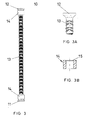
- the double-headed dowels 10 used here are detailed in the Figures 3, 3a and 3b shown.
- the double-head dowels 10 consist of a dowel pin 13 at its lower end a lower head 11 and at its upper end an upper head 12 is formed. These two heads 11, 12 are integrally formed on a dowel pin 13 preferably integrally. In the present case, a ribbed structural steel is used here.
- the double-headed plug 10 is made in one piece.
- the heads 11, 12 can be formed either by a pressing process or by a forging process. At higher loads, it is advantageous to reinforce these heads 11, 12.
- the solution will certainly be changed in terms of production technology such that the double-headed plug 10 is manufactured in a casting process, for example, wherein the plug bolt 13 is integrally formed with the heads 11, 12 and the reinforcing rings 14.
- FIG. 4 a possible installation arrangement of the inventive punching shear baskets 1 is shown.
- the support element is designated S. In this case, it is a column with a square cross-section.
- the punching reinforcement baskets 1 accordingly extend perpendicularly away from each side of the support member S in the orthogonal direction. Only for the sake of clarity not more punching shear baskets 1 were shown, but in principle one will always attach the same amount of punching shear baskets 1 on each side, if it is a central support element.
- the laying plans will be different if the support member is located at an edge or at a corner of a floor or ceiling panel.
Landscapes
- Engineering & Computer Science (AREA)
- Architecture (AREA)
- Civil Engineering (AREA)
- Structural Engineering (AREA)
- Joining Of Building Structures In Genera (AREA)
- Reinforcement Elements For Buildings (AREA)
- Polishing Bodies And Polishing Tools (AREA)
- Perforating, Stamping-Out Or Severing By Means Other Than Cutting (AREA)
Claims (14)
- Armature de poinçonnement pour des plaques de sol ou de plafond (P) comprenant une pluralité de chevilles à tête double (10), qui sont reliées fixement à au moins une barre horizontale (2), caractérisée en ce que l'armature de poinçonnement est constituée d'étriers (4) en U, qui sont reliés les uns aux autres au moyen de barres longitudinales (2) latérales, fixées sur leurs branches (5) parallèles, et forment ainsi une corbeille d'armature de poinçonnement (1), sur laquelle les chevilles à tête double (10) sont soudées sur les barres longitudinales (2) latérales.
- Armature de poinçonnement selon la revendication 1, caractérisée en ce qu'à chaque fois deux barres longitudinales (2) sont soudées sur les branches (5) parallèles sur chaque côté des étriers (4) en U.
- Armature de poinçonnement selon la revendication 1, caractérisée en ce qu'au moins une barre longitudinale (3) est soudée comme barre de palier sur les traverses (6) des étriers (4) en U, laquelle barre sert de support pour un niveau d'armature (O) supérieur des plaques de sol ou de plafond (P).
- Armature de poinçonnement selon la revendication 1, caractérisée en ce que les extrémités des branches (5) des étriers (4) en U sont conçues comme des pieds de base (7).
- Armature de poinçonnement selon la revendication 2, caractérisée en ce que plusieurs chevilles à tête double (10) sont disposées entre deux brides (4) en U voisines sur chaque côté sur les deux barres longitudinales (2).
- Armature de poinçonnement selon la revendication 1, caractérisée en ce qu'à chaque fois trois barres longitudinales (2) sont disposées sur les deux côtés, les barres longitudinales (2) supérieures étant soudées dans la zone de la flexion entre la traverse (6) respective et les branches (5) des étriers (4) en U.
- Armature de poinçonnement selon la revendication 1, caractérisée en ce que chaque cheville à double tête (10) est constituée d'un boulon chevillé (13) avec une tête (11) inférieure et une tête (12) supérieure.
- Armature de poinçonnement selon la revendication 6, caractérisée en ce que les chevilles à double tête (10) sont soudées dessus, de telle sorte que, dans la position de montage, leurs têtes (11) inférieures arrivent au moins approximativement à la hauteur d'une armature de flexion inférieure (U), et la longueur de son boulon chevillé (13) est dimensionnée de telle sorte que les têtes (12) supérieures des chevilles à double tête (10) arrivent à la hauteur de l'armature de flexion supérieure (O) d'une plaque de sol ou de plafond (P), dans laquelle l'armature de flexion est montée.
- Armature de poinçonnement selon la revendication 6, caractérisée en ce que les chevilles à double tête (10) sont constituées d'un boulon chevillé (13) avec des têtes (11, 12) formées dessus d'une seule pièce.
- Armature de poinçonnement selon la revendication 6, caractérisée en ce que les têtes (11, 12) sont formées sur les boulons chevillés (13) au moyen d'un processus de compression.
- Armature de poinçonnement selon la revendication 6, caractérisée en ce que les têtes (11, 12) sont renforcées chacune au moyen d'une bague (14) posée dessus.
- Armature de poinçonnement selon la revendication 7, caractérisée en ce que les bagues de renfort (14) ont été enfilées avant le formage des têtes (11, 12) sur le boulon chevillé (13) et sont déplacées après leur formage jusqu'aux têtes (11, 12) formées dessus.
- Armature de poinçonnement selon la revendication 6, caractérisée en ce que les boulons chevillées (13) sont fabriqués dans un acier nervuré.
- Armature de poinçonnement selon la revendication 4, caractérisée en ce que des chaussures (8) fabriquées en plastique sont emboîtées sur les brides (4) en U sur ses pieds de base (7).
Priority Applications (1)
| Application Number | Priority Date | Filing Date | Title |
|---|---|---|---|
| PL10164757T PL2290167T3 (pl) | 2009-08-21 | 2010-06-02 | Zbrojenie zabezpieczające przed przebiciem |
Applications Claiming Priority (1)
| Application Number | Priority Date | Filing Date | Title |
|---|---|---|---|
| CH01301/09A CH701682A1 (de) | 2009-08-21 | 2009-08-21 | Durchstanzbewehrung. |
Publications (2)
| Publication Number | Publication Date |
|---|---|
| EP2290167A1 EP2290167A1 (fr) | 2011-03-02 |
| EP2290167B1 true EP2290167B1 (fr) | 2012-02-29 |
Family
ID=42109751
Family Applications (1)
| Application Number | Title | Priority Date | Filing Date |
|---|---|---|---|
| EP10164757A Not-in-force EP2290167B1 (fr) | 2009-08-21 | 2010-06-02 | Armature de poinçonnement |
Country Status (4)
| Country | Link |
|---|---|
| EP (1) | EP2290167B1 (fr) |
| AT (1) | ATE547577T1 (fr) |
| CH (1) | CH701682A1 (fr) |
| PL (1) | PL2290167T3 (fr) |
Families Citing this family (4)
| Publication number | Priority date | Publication date | Assignee | Title |
|---|---|---|---|---|
| KR100971736B1 (ko) * | 2009-04-03 | 2010-07-21 | 이재호 | 상하 각각 이중 앵커리지 기능을 갖는 전단보강재 |
| GB2491339A (en) * | 2011-04-15 | 2012-12-05 | Stephen Bell | Punching shear reinforcement structure for pre cast concrete planks |
| WO2021209686A1 (fr) * | 2020-04-16 | 2021-10-21 | Peikko Group Oy | Élément allongé à tête |
| EP4112833A1 (fr) * | 2021-06-28 | 2023-01-04 | AVI Alpenländische Veredelungs-Industrie Gesellschaft m.b.H. | Agencement de renfort permettant d'augmenter la résistance au poinçonnage, ainsi que procédé associé |
Family Cites Families (18)
| Publication number | Priority date | Publication date | Assignee | Title |
|---|---|---|---|---|
| FR2383287A1 (fr) * | 1977-03-10 | 1978-10-06 | Trefilerie Normande Ste Nle | Armature utilisable pour la fabrication au moyen d'un moule, d'articles en beton arme |
| DE2727159C3 (de) | 1977-06-16 | 1980-05-08 | 7000 Stuttgart | Schubbewehrung für auf Betonstützen aufgelagerte Flachdecken aus Stahl- oder Spannbeton |
| DE2924449C2 (de) | 1979-06-18 | 1986-03-27 | Linde Ag, 6200 Wiesbaden | Verfahren zum Reinigen von Abwasser nach dem Belebtschlammverfahren |
| AT378806B (de) * | 1983-11-17 | 1985-10-10 | Avi Alpenlaendische Vered | Buegelkorb |
| AT382188B (de) | 1984-07-24 | 1987-01-26 | Avi Alpenlaendische Vered | Schubbewehrungssystem fuer flaechentragwerke |
| EP0184995B1 (fr) | 1984-12-12 | 1991-07-31 | Ulisse C. Aschwanden | Système d'armature empêchant le cissaillement |
| AT390099B (de) * | 1987-02-06 | 1990-03-12 | Avi Alpenlaendische Vered | Die verwendung einer fuer bauteile aus stahlbeton bestimmten bewehrung |
| CH688519A5 (de) | 1994-06-24 | 1997-10-31 | Fischer Reinach Ag | Durchstanz-Bewehrung fuer gestuetzte Betondecken im Bereiche von deren Stuetzen sowie Verfahren zu deren Herstellung und Biegemaschine. |
| GB2328455A (en) * | 1996-08-21 | 1999-02-24 | Jubin Motamed | Concrete slab shear reinforcement |
| DE19756358A1 (de) | 1997-12-18 | 1999-07-01 | Deha Ankersysteme | Schubbewehrung für Flachdecken und Dübelleiste hierfür |
| DE29807557U1 (de) | 1998-04-30 | 1999-09-09 | Schöck Bauteile GmbH, 76534 Baden-Baden | Bauelement zur Schubbewehrung |
| DE29903737U1 (de) | 1999-03-02 | 1999-08-12 | Schöck Bauteile GmbH, 76534 Baden-Baden | Bauelement zur Schubbewehrung |
| DE10001595A1 (de) * | 2000-01-17 | 2001-07-19 | Deha Ankersysteme | Bewehrung für Stahlbetondecken |
| DE20016373U1 (de) | 2000-09-21 | 2000-12-28 | Egon Elsäßer Bauindustrie GmbH & Co. KG, 78187 Geisingen | Vorrichtung für den einfachen Einbau von Durchstanzbewehrungen in Decken |
| CH695106A5 (de) | 2001-01-23 | 2005-12-15 | Fischer Reinach Ag | Verfahren zur Herstellung einer Schubarmierung in gestützten Betondecken. |
| DE20106428U1 (de) | 2001-04-11 | 2001-07-19 | Deutsche Kahneisen Gesellschaft mbH, 12057 Berlin | Dübelleiste für Durchstanzbewehrungen |
| DE202005013048U1 (de) * | 2005-08-18 | 2005-12-01 | Schöck Bauteile GmbH | Bauelement zur Schubbewehrung |
| ES2389563T3 (es) | 2006-12-14 | 2012-10-29 | F.J. Aschwanden Ag | Elemento de armadura para la absorción de fuerzas en placas hormigonadas en el sector de elementos de apoyo |
-
2009
- 2009-08-21 CH CH01301/09A patent/CH701682A1/de unknown
-
2010
- 2010-06-02 EP EP10164757A patent/EP2290167B1/fr not_active Not-in-force
- 2010-06-02 AT AT10164757T patent/ATE547577T1/de active
- 2010-06-02 PL PL10164757T patent/PL2290167T3/pl unknown
Also Published As
| Publication number | Publication date |
|---|---|
| PL2290167T3 (pl) | 2012-06-29 |
| CH701682A1 (de) | 2011-02-28 |
| ATE547577T1 (de) | 2012-03-15 |
| EP2290167A1 (fr) | 2011-03-02 |
Similar Documents
| Publication | Publication Date | Title |
|---|---|---|
| EP2157260B1 (fr) | Coffrage doté d'un dispositif d'ancrage arrière | |
| EP2963205B1 (fr) | Dispositif de coffrage | |
| EP2290167A1 (fr) | Armature de poinçonnement | |
| WO2017037106A1 (fr) | Poutre maîtresse pour structures de plancher, structure de plancher et procédé de fabrication | |
| WO2001053623A2 (fr) | Piece en beton arme ou en beton precontraint pouvant etre soumise a une force transversale | |
| EP2977526B1 (fr) | Équerre de fixation pour coffrages de rives de dalle | |
| EP1033454B1 (fr) | Elément de construction pour armature de cisaillement | |
| WO2011012480A1 (fr) | Élément de béton armé à armature formée d'éléments de tôle en z | |
| EP2166171B1 (fr) | Armature de poinçonnement d'une structure en béton armé contre le poinçonnement aux alentours de la zone d'appui d'une dalle | |
| EP2080841B1 (fr) | Elément de pose de dalles en console | |
| EP1932978B1 (fr) | Elément d'armature pour l'absorption de forces dans des plaques de béton dans la zone d'éléments d'appui | |
| DE20304644U1 (de) | Vorrichtung zur Höhenpositionierung von Bewehrungslagen und Rohrregistern bei der Betonkernaktivierung | |
| EP2295667B1 (fr) | Elément d'armature pour la pose dans des composants en béton | |
| EP2143851B1 (fr) | Elément d'armature pour l'absorption de forces dans les bords latéraux de plaques en béton aux alentours d'éléments d'appui | |
| WO2004059216A1 (fr) | Element de construction prefabrique en particulier element de construction ou de paroi constitue d'un materiau durci et procede de production d'un tel element de construction | |
| DE202006007405U1 (de) | Schubbewehrungselement | |
| AT10698U1 (de) | Verbindungselement und hohlwandelement mit solchen verbindungselementen | |
| AT270962B (de) | Vorgefertigtes, großformatiges, dünnwandiges Stahlbeton-Tafelelement | |
| DE19924418A1 (de) | Bauelement zur Schubbewehrung | |
| DE10001595A1 (de) | Bewehrung für Stahlbetondecken | |
| DE2303880A1 (de) | Abstandhalter fuer bewehrungseinlagen in stahlbetondecken | |
| DE9210992U1 (de) | Dübelanordnung für aus Beton hergestellte Industriefußböden | |
| DE1608527C (de) | Untertageausbau | |
| DE19716410A1 (de) | Konstruktionsträger | |
| AT241769B (de) | Ortsbetonrippendecke |
Legal Events
| Date | Code | Title | Description |
|---|---|---|---|
| PUAI | Public reference made under article 153(3) epc to a published international application that has entered the european phase |
Free format text: ORIGINAL CODE: 0009012 |
|
| AK | Designated contracting states |
Kind code of ref document: A1 Designated state(s): AL AT BE BG CH CY CZ DE DK EE ES FI FR GB GR HR HU IE IS IT LI LT LU LV MC MK MT NL NO PL PT RO SE SI SK SM TR |
|
| AX | Request for extension of the european patent |
Extension state: BA ME RS |
|
| RAP1 | Party data changed (applicant data changed or rights of an application transferred) |
Owner name: BOSSARD + STAERKLE AG |
|
| 17P | Request for examination filed |
Effective date: 20110609 |
|
| GRAP | Despatch of communication of intention to grant a patent |
Free format text: ORIGINAL CODE: EPIDOSNIGR1 |
|
| RIC1 | Information provided on ipc code assigned before grant |
Ipc: E04C 5/18 20060101ALI20110809BHEP Ipc: E04C 5/06 20060101AFI20110809BHEP Ipc: E04B 5/43 20060101ALI20110809BHEP |
|
| GRAS | Grant fee paid |
Free format text: ORIGINAL CODE: EPIDOSNIGR3 |
|
| GRAA | (expected) grant |
Free format text: ORIGINAL CODE: 0009210 |
|
| AK | Designated contracting states |
Kind code of ref document: B1 Designated state(s): AL AT BE BG CH CY CZ DE DK EE ES FI FR GB GR HR HU IE IS IT LI LT LU LV MC MK MT NL NO PL PT RO SE SI SK SM TR |
|
| REG | Reference to a national code |
Ref country code: CH Ref legal event code: EP Ref country code: GB Ref legal event code: FG4D Free format text: NOT ENGLISH |
|
| REG | Reference to a national code |
Ref country code: AT Ref legal event code: REF Ref document number: 547577 Country of ref document: AT Kind code of ref document: T Effective date: 20120315 |
|
| REG | Reference to a national code |
Ref country code: IE Ref legal event code: FG4D Free format text: LANGUAGE OF EP DOCUMENT: GERMAN |
|
| REG | Reference to a national code |
Ref country code: CH Ref legal event code: NV Representative=s name: SCHNEIDER FELDMANN AG PATENT- UND MARKENANWAELTE |
|
| REG | Reference to a national code |
Ref country code: DE Ref legal event code: R096 Ref document number: 502010000471 Country of ref document: DE Effective date: 20120419 |
|
| REG | Reference to a national code |
Ref country code: NL Ref legal event code: VDEP Effective date: 20120229 |
|
| REG | Reference to a national code |
Ref country code: PL Ref legal event code: T3 |
|
| LTIE | Lt: invalidation of european patent or patent extension |
Effective date: 20120229 |
|
| PG25 | Lapsed in a contracting state [announced via postgrant information from national office to epo] |
Ref country code: IS Free format text: LAPSE BECAUSE OF FAILURE TO SUBMIT A TRANSLATION OF THE DESCRIPTION OR TO PAY THE FEE WITHIN THE PRESCRIBED TIME-LIMIT Effective date: 20120629 Ref country code: LT Free format text: LAPSE BECAUSE OF FAILURE TO SUBMIT A TRANSLATION OF THE DESCRIPTION OR TO PAY THE FEE WITHIN THE PRESCRIBED TIME-LIMIT Effective date: 20120229 Ref country code: NL Free format text: LAPSE BECAUSE OF FAILURE TO SUBMIT A TRANSLATION OF THE DESCRIPTION OR TO PAY THE FEE WITHIN THE PRESCRIBED TIME-LIMIT Effective date: 20120229 Ref country code: NO Free format text: LAPSE BECAUSE OF FAILURE TO SUBMIT A TRANSLATION OF THE DESCRIPTION OR TO PAY THE FEE WITHIN THE PRESCRIBED TIME-LIMIT Effective date: 20120529 Ref country code: HR Free format text: LAPSE BECAUSE OF FAILURE TO SUBMIT A TRANSLATION OF THE DESCRIPTION OR TO PAY THE FEE WITHIN THE PRESCRIBED TIME-LIMIT Effective date: 20120229 |
|
| REG | Reference to a national code |
Ref country code: CH Ref legal event code: PFA Owner name: SPAETER ZUG AG Free format text: BOSSARD + STAERKLE AG#IM GOEBLI 61#6301 ZUG (CH) -TRANSFER TO- SPAETER ZUG AG#IM GOEBLI 61#6300 ZUG (CH) |
|
| PG25 | Lapsed in a contracting state [announced via postgrant information from national office to epo] |
Ref country code: FI Free format text: LAPSE BECAUSE OF FAILURE TO SUBMIT A TRANSLATION OF THE DESCRIPTION OR TO PAY THE FEE WITHIN THE PRESCRIBED TIME-LIMIT Effective date: 20120229 Ref country code: GR Free format text: LAPSE BECAUSE OF FAILURE TO SUBMIT A TRANSLATION OF THE DESCRIPTION OR TO PAY THE FEE WITHIN THE PRESCRIBED TIME-LIMIT Effective date: 20120530 Ref country code: LV Free format text: LAPSE BECAUSE OF FAILURE TO SUBMIT A TRANSLATION OF THE DESCRIPTION OR TO PAY THE FEE WITHIN THE PRESCRIBED TIME-LIMIT Effective date: 20120229 Ref country code: PT Free format text: LAPSE BECAUSE OF FAILURE TO SUBMIT A TRANSLATION OF THE DESCRIPTION OR TO PAY THE FEE WITHIN THE PRESCRIBED TIME-LIMIT Effective date: 20120629 |
|
| REG | Reference to a national code |
Ref country code: DE Ref legal event code: R081 Ref document number: 502010000471 Country of ref document: DE Owner name: SPAETER ZUG AG, CH Free format text: FORMER OWNER: BOSSARD & STAERKLE AG, ZUG, CH Effective date: 20120726 Ref country code: DE Ref legal event code: R082 Ref document number: 502010000471 Country of ref document: DE Representative=s name: ZELLENTIN & PARTNER GBR, DE Effective date: 20120726 |
|
| REG | Reference to a national code |
Ref country code: IE Ref legal event code: FD4D |
|
| PG25 | Lapsed in a contracting state [announced via postgrant information from national office to epo] |
Ref country code: CY Free format text: LAPSE BECAUSE OF FAILURE TO SUBMIT A TRANSLATION OF THE DESCRIPTION OR TO PAY THE FEE WITHIN THE PRESCRIBED TIME-LIMIT Effective date: 20120229 |
|
| PG25 | Lapsed in a contracting state [announced via postgrant information from national office to epo] |
Ref country code: SE Free format text: LAPSE BECAUSE OF FAILURE TO SUBMIT A TRANSLATION OF THE DESCRIPTION OR TO PAY THE FEE WITHIN THE PRESCRIBED TIME-LIMIT Effective date: 20120229 Ref country code: RO Free format text: LAPSE BECAUSE OF FAILURE TO SUBMIT A TRANSLATION OF THE DESCRIPTION OR TO PAY THE FEE WITHIN THE PRESCRIBED TIME-LIMIT Effective date: 20120229 Ref country code: IE Free format text: LAPSE BECAUSE OF FAILURE TO SUBMIT A TRANSLATION OF THE DESCRIPTION OR TO PAY THE FEE WITHIN THE PRESCRIBED TIME-LIMIT Effective date: 20120229 Ref country code: EE Free format text: LAPSE BECAUSE OF FAILURE TO SUBMIT A TRANSLATION OF THE DESCRIPTION OR TO PAY THE FEE WITHIN THE PRESCRIBED TIME-LIMIT Effective date: 20120229 Ref country code: SI Free format text: LAPSE BECAUSE OF FAILURE TO SUBMIT A TRANSLATION OF THE DESCRIPTION OR TO PAY THE FEE WITHIN THE PRESCRIBED TIME-LIMIT Effective date: 20120229 Ref country code: CZ Free format text: LAPSE BECAUSE OF FAILURE TO SUBMIT A TRANSLATION OF THE DESCRIPTION OR TO PAY THE FEE WITHIN THE PRESCRIBED TIME-LIMIT Effective date: 20120229 Ref country code: DK Free format text: LAPSE BECAUSE OF FAILURE TO SUBMIT A TRANSLATION OF THE DESCRIPTION OR TO PAY THE FEE WITHIN THE PRESCRIBED TIME-LIMIT Effective date: 20120229 |
|
| PG25 | Lapsed in a contracting state [announced via postgrant information from national office to epo] |
Ref country code: IT Free format text: LAPSE BECAUSE OF FAILURE TO SUBMIT A TRANSLATION OF THE DESCRIPTION OR TO PAY THE FEE WITHIN THE PRESCRIBED TIME-LIMIT Effective date: 20120229 Ref country code: SK Free format text: LAPSE BECAUSE OF FAILURE TO SUBMIT A TRANSLATION OF THE DESCRIPTION OR TO PAY THE FEE WITHIN THE PRESCRIBED TIME-LIMIT Effective date: 20120229 |
|
| BERE | Be: lapsed |
Owner name: BOSSARD + STAERKLE A.G. Effective date: 20120630 |
|
| PLBE | No opposition filed within time limit |
Free format text: ORIGINAL CODE: 0009261 |
|
| STAA | Information on the status of an ep patent application or granted ep patent |
Free format text: STATUS: NO OPPOSITION FILED WITHIN TIME LIMIT |
|
| PG25 | Lapsed in a contracting state [announced via postgrant information from national office to epo] |
Ref country code: MC Free format text: LAPSE BECAUSE OF NON-PAYMENT OF DUE FEES Effective date: 20120630 |
|
| 26N | No opposition filed |
Effective date: 20121130 |
|
| PG25 | Lapsed in a contracting state [announced via postgrant information from national office to epo] |
Ref country code: MK Free format text: LAPSE BECAUSE OF FAILURE TO SUBMIT A TRANSLATION OF THE DESCRIPTION OR TO PAY THE FEE WITHIN THE PRESCRIBED TIME-LIMIT Effective date: 20120229 |
|
| REG | Reference to a national code |
Ref country code: DE Ref legal event code: R097 Ref document number: 502010000471 Country of ref document: DE Effective date: 20121130 |
|
| REG | Reference to a national code |
Ref country code: FR Ref legal event code: ST Effective date: 20130228 |
|
| PG25 | Lapsed in a contracting state [announced via postgrant information from national office to epo] |
Ref country code: ES Free format text: LAPSE BECAUSE OF FAILURE TO SUBMIT A TRANSLATION OF THE DESCRIPTION OR TO PAY THE FEE WITHIN THE PRESCRIBED TIME-LIMIT Effective date: 20120609 Ref country code: BE Free format text: LAPSE BECAUSE OF NON-PAYMENT OF DUE FEES Effective date: 20120630 Ref country code: FR Free format text: LAPSE BECAUSE OF NON-PAYMENT OF DUE FEES Effective date: 20120702 |
|
| PG25 | Lapsed in a contracting state [announced via postgrant information from national office to epo] |
Ref country code: MT Free format text: LAPSE BECAUSE OF FAILURE TO SUBMIT A TRANSLATION OF THE DESCRIPTION OR TO PAY THE FEE WITHIN THE PRESCRIBED TIME-LIMIT Effective date: 20120229 Ref country code: BG Free format text: LAPSE BECAUSE OF FAILURE TO SUBMIT A TRANSLATION OF THE DESCRIPTION OR TO PAY THE FEE WITHIN THE PRESCRIBED TIME-LIMIT Effective date: 20120529 |
|
| PG25 | Lapsed in a contracting state [announced via postgrant information from national office to epo] |
Ref country code: AL Free format text: LAPSE BECAUSE OF FAILURE TO SUBMIT A TRANSLATION OF THE DESCRIPTION OR TO PAY THE FEE WITHIN THE PRESCRIBED TIME-LIMIT Effective date: 20120229 |
|
| PG25 | Lapsed in a contracting state [announced via postgrant information from national office to epo] |
Ref country code: TR Free format text: LAPSE BECAUSE OF FAILURE TO SUBMIT A TRANSLATION OF THE DESCRIPTION OR TO PAY THE FEE WITHIN THE PRESCRIBED TIME-LIMIT Effective date: 20120229 |
|
| PG25 | Lapsed in a contracting state [announced via postgrant information from national office to epo] |
Ref country code: SM Free format text: LAPSE BECAUSE OF FAILURE TO SUBMIT A TRANSLATION OF THE DESCRIPTION OR TO PAY THE FEE WITHIN THE PRESCRIBED TIME-LIMIT Effective date: 20120229 Ref country code: LU Free format text: LAPSE BECAUSE OF NON-PAYMENT OF DUE FEES Effective date: 20120602 |
|
| PG25 | Lapsed in a contracting state [announced via postgrant information from national office to epo] |
Ref country code: HU Free format text: LAPSE BECAUSE OF FAILURE TO SUBMIT A TRANSLATION OF THE DESCRIPTION OR TO PAY THE FEE WITHIN THE PRESCRIBED TIME-LIMIT Effective date: 20100602 |
|
| PGFP | Annual fee paid to national office [announced via postgrant information from national office to epo] |
Ref country code: DE Payment date: 20140528 Year of fee payment: 5 |
|
| PGFP | Annual fee paid to national office [announced via postgrant information from national office to epo] |
Ref country code: PL Payment date: 20140411 Year of fee payment: 5 |
|
| GBPC | Gb: european patent ceased through non-payment of renewal fee |
Effective date: 20140602 |
|
| PG25 | Lapsed in a contracting state [announced via postgrant information from national office to epo] |
Ref country code: GB Free format text: LAPSE BECAUSE OF NON-PAYMENT OF DUE FEES Effective date: 20140602 |
|
| REG | Reference to a national code |
Ref country code: DE Ref legal event code: R119 Ref document number: 502010000471 Country of ref document: DE |
|
| PG25 | Lapsed in a contracting state [announced via postgrant information from national office to epo] |
Ref country code: DE Free format text: LAPSE BECAUSE OF NON-PAYMENT OF DUE FEES Effective date: 20160101 |
|
| REG | Reference to a national code |
Ref country code: AT Ref legal event code: MM01 Ref document number: 547577 Country of ref document: AT Kind code of ref document: T Effective date: 20150602 |
|
| PG25 | Lapsed in a contracting state [announced via postgrant information from national office to epo] |
Ref country code: PL Free format text: LAPSE BECAUSE OF NON-PAYMENT OF DUE FEES Effective date: 20150602 |
|
| PGFP | Annual fee paid to national office [announced via postgrant information from national office to epo] |
Ref country code: CH Payment date: 20160929 Year of fee payment: 7 |
|
| PG25 | Lapsed in a contracting state [announced via postgrant information from national office to epo] |
Ref country code: AT Free format text: LAPSE BECAUSE OF NON-PAYMENT OF DUE FEES Effective date: 20150602 |
|
| REG | Reference to a national code |
Ref country code: CH Ref legal event code: PL |
|
| PG25 | Lapsed in a contracting state [announced via postgrant information from national office to epo] |
Ref country code: CH Free format text: LAPSE BECAUSE OF NON-PAYMENT OF DUE FEES Effective date: 20170630 Ref country code: LI Free format text: LAPSE BECAUSE OF NON-PAYMENT OF DUE FEES Effective date: 20170630 |