EP2290169A1 - Profilmodul zur Herstellung einer Dachkonstruktion - Google Patents
Profilmodul zur Herstellung einer Dachkonstruktion Download PDFInfo
- Publication number
- EP2290169A1 EP2290169A1 EP09010807A EP09010807A EP2290169A1 EP 2290169 A1 EP2290169 A1 EP 2290169A1 EP 09010807 A EP09010807 A EP 09010807A EP 09010807 A EP09010807 A EP 09010807A EP 2290169 A1 EP2290169 A1 EP 2290169A1
- Authority
- EP
- European Patent Office
- Prior art keywords
- profile
- guide
- guide profile
- carriage element
- module according
- Prior art date
- Legal status (The legal status is an assumption and is not a legal conclusion. Google has not performed a legal analysis and makes no representation as to the accuracy of the status listed.)
- Granted
Links
Images

Classifications
-
- E—FIXED CONSTRUCTIONS
- E04—BUILDING
- E04D—ROOF COVERINGS; SKY-LIGHTS; GUTTERS; ROOF-WORKING TOOLS
- E04D3/00—Roof covering by making use of flat or curved slabs or stiff sheets
- E04D3/36—Connecting; Fastening
- E04D3/3607—Connecting; Fastening the fastening means comprising spacer means adapted to the shape of the profiled roof covering
-
- E—FIXED CONSTRUCTIONS
- E04—BUILDING
- E04D—ROOF COVERINGS; SKY-LIGHTS; GUTTERS; ROOF-WORKING TOOLS
- E04D12/00—Non-structural supports for roofing materials, e.g. battens, boards
- E04D12/004—Battens
-
- E—FIXED CONSTRUCTIONS
- E04—BUILDING
- E04D—ROOF COVERINGS; SKY-LIGHTS; GUTTERS; ROOF-WORKING TOOLS
- E04D3/00—Roof covering by making use of flat or curved slabs or stiff sheets
- E04D3/36—Connecting; Fastening
- E04D3/361—Connecting; Fastening by specially-profiled marginal portions of the slabs or sheets
- E04D2003/3615—Separate fastening elements fixed to the roof structure and consisting of parts permitting relative movement to each other, e.g. for thermal expansion
Definitions
- the invention relates to a profile module for producing a roof construction according to the preamble of patent claim 1.
- the invention further relates to a roof construction according to the preamble of patent claim 10 and to a slide element for use in a profile module according to patent claim 14.
- the invention aims to remedy this situation.
- the invention is based on the object to provide a profile for producing a roof construction and a roof construction, in which a caused by thermal deformation noise is counteracted. According to the invention, this object is solved by the features of claim 1.
- a profile module for producing a roof construction in which a caused by thermal deformation noise is counteracted.
- the slider arranged within the guide profile slide elements are used to attach the plate elements.
- the floating connection of the plate elements with the guide profile on the slide elements noise developments due to thermal deformation of the plate elements are avoided.
- the opening is designed as a slot which extends in the longitudinal direction over the entire guide profile.
- the at least one slide element has a shoulder which projects through the opening of the guide profile.
- the guide profile has a substantially rectangular cross section.
- a good circulation of the profile module on the surfaces of the rafters of a roof construction is effected.
- the carriage element is designed as a hollow profile part. As a result, the flexibility of the carriage member is further increased.
- the carriage member on its side opposite the opening of the guide profile on a concavity, whereby on this side, the contact surface between the guide rail and carriage element is interrupted.
- the friction between the carriage element and the profile module is reduced, whereby the sliding properties of the carriage element are improved within the guide profile.
- the concavity of the recording of the head of a screw by means of which, for example, a plate member can be connected to the carriage member.
- a spacer for receiving a plate element is arranged on the carriage element.
- the spacer serves to approximate the carriage element with the shape of the plate element.
- the spacer may have a curved surface section for supporting the plate element, which essentially describes the shape of a hemisphere.
- the spacer may be designed as a separate component, which is bolted to the carriage part.
- the spacer may also be integrally connected to the carriage member.
- the spacer is preferably integrally formed together with the carriage element as a plastic injection molded part.
- the rafters are at least partially profile modules according to the present invention.
- noise developments are avoided in addition, which can be caused by different expansions of rafters and slats due to thermal effects.
- the rafters comprise at least partially two longitudinally superimposed guide profiles, wherein a second guide profile is connected to at least one floating within a first guide profile slide member.
- the subject matter of the invention is furthermore a slide element for the floating attachment of a plate element to a guide profile having the features of patent claim 14.
- a slide element permits floating mounting of a plate element within a guide profile, whereby noise developments due to deformations of the plate elements due to thermal influence are avoided ,
- the plate elements used for the purpose of the spacer is dome-shaped or trapezoidal.
- slide elements and spacers are designed in one piece as a plastic injection molded part.
- the assembly of the plates on the guide profile is simplified.
- the selected as an embodiment profile module 1 consists essentially of a guide profile 2, in which a plurality of carriage elements 3 are arranged floating.
- a "floating storage” is to be understood below a movable in the horizontal and vertical direction storage.
- the guide profile 2 is formed in the embodiment substantially hollow cuboid. On its cover side 21, a longitudinally continuous gap-like opening 22 is introduced into the guide profile 2. The opening 22 serves for the passage of a shoulder 32 of the carriage elements 3. On its bottom side 23 arranged opposite the cover side 21, two longitudinally parallel strips 24 are formed spaced apart from one another. In the exemplary embodiment, the spacing between the strips 24 essentially corresponds to the width of the slot-like opening 22 of the guide profile 2. The strips 24 each define a groove 25. The two grooves 25 thus formed serve to receive two webs formed on the outside of the cover 21 26.
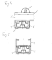
- the guide profile 2 is thus designed such that it is stackable on a further guide profile, wherein the webs 26 of the lower guide profile engage two in the grooves 25 of the upper guide profile 2. The strips 24 of the upper guide profile 2 limit thereby the slot-like opening 22 of the lower guide profile 2 (see. Fig. 5 ).
- the carriage element 3 has a substantially cuboid base body 31, on the upper side of which the opening 22 of the guide profile 2 faces a narrower, substantially parallelepipedal shoulder 32, which passes through the opening 22 of the guide profile 2. Opposite the shoulder 32, a recess 31 is inserted into the carriage element 3, whereby the contact surface between the guide profile 2 and the carriage element 3 is interrupted on this side.
- the indentation 33 simultaneously serves to receive the head of a screw for fastening a plate element 5.
- the cross-section of the carriage element 3 is designed such that the base body 31 is smaller in height and width dimensions than the inner space bounded by the guide profile 2.
- the shoulder 32 of the carriage element 2 is dimensioned to be narrower than the width of the slot-shaped opening 22, so that the carriage element 3 can be moved in the horizontal as well as in the vertical direction within the guide profile 2.
- the carriage element is formed as a plastic molded hollow profile part with a length of ten centimeters.
- a spacer 4 is arranged.
- the spacer 4 consists essentially of a dome part 41, in the middle of a guide 42 is arranged to carry out a screw.
- the ball member 41 is formed substantially hemispherical.
- the spacer may also have a trapezoidal or otherwise formed head part, which is adapted to the design of the plate elements 5 to be used.
- the spacer 4 is integrally formed on the shoulder 32 of the Schlitterielements 3.
- the heel holder 4 may alternatively be formed as a separate component and connected, for example via a screw connection with the carriage member.
- FIG. 4 is an example of an arrangement of two guide modules 1 shown in rafter and battens.
- the guide module 1 'arranged at the bottom assumes the function of raking.
- the profile module according to the invention is not limited to the use for the design of roof structures. It is equally suitable for the production of facade structures for the vertical attachment of panel elements to building facades, which also avoided by thermal effects caused noise emissions.
Landscapes
- Engineering & Computer Science (AREA)
- Architecture (AREA)
- Civil Engineering (AREA)
- Structural Engineering (AREA)
- Mechanical Engineering (AREA)
- Roof Covering Using Slabs Or Stiff Sheets (AREA)
Abstract
Description
- Die Erfindung betrifft ein Profilmodul zur Herstellung einer Dachkonstruktion nach dem Oberbegriff des Patentanspruchs 1. Die Erfindung betrifft weiterhin eine Dachkonstruktion nach dem Oberbegriff des Patentanspruchs 10 sowie ein Schlittenelement zum Einsatz in einem Profilmodul nach dem Patentanspruch 14.
- Zur Überdachung beispielsweise von Terrassen ist es bekannt, Profil- bzw. Sprossenkonstruktionen einzusetzen, welche Plattenelemente aufnehmen. Eine solche Dachkonstruktion erfolgt regelmäßig unter Einsatz von Sparren, welche beabstandet zueinander angeordnet sind, und auf denen beabstandet zueinander Dachlatten in Querrichtung befestigt sind. Auf diesen Dachlatten sind vorzugsweise aus thermoplastischem Kunststoff hergestellte Plattenelemente befestigt.
- Nachteilig an den vorbekannten Konstruktionen ist, dass sich die aus thermoplastischem Kunststoff bestehenden Plattenelemente unter Wärmeeinwirkungen verformen, wobei es zu störenden Geräuschentwicklungen kommen kann. Diese Geräuschentwicklungen sind insbesondere auf Relativbewegungen zwischen den Dachlatten bzw. Profilen und Plattenelementen auf Grund der Materialausdehnungen der Plattenelemente zurückzuführen.
- Hier will die Erfindung Abhilfe schaffen. Der Erfindung liegt die Aufgabe zu Grunde, ein Profil zur Herstellung einer Dachkonstruktion sowie eine Dachkonstruktion zu schaffen, bei der einer durch thermische Verformung bedingten Geräuschentwicklung entgegengewirkt ist. Gemäß der Erfindung wird diese Aufgabe durch die Merkmale des Patentanspruchs 1 gelöst.
- Mit der Erfindung ist ein Profilmodul zur Herstellung einer Dachkonstruktion geschaffen, bei dem einer durch thermische Verformung bedingten Geräuschentwicklung entgegengewirkt ist. Die schwimmend innerhalb des Führungsprofils angeordneten Schlittenelemente dienen der Befestigung der Plattenelemente. Durch die schwimmende Verbindung der Plattenelemente mit dem Führungsprofil über die Schlittenelemente werden Geräuschentwicklungen auf Grund von thermischen Verformungen der Plattenelemente vermieden.
- In Weiterbildung der Erfindung ist die Öffnung als Schlitz ausgeführt, welche sich in Längsrichtung über das gesamte Führungsprofil erstreckt. Hierdurch ist das nachträgliche Einbringen von Schlittenelementen in das Führungsprofil sowie ein Austausch defekter Schlittenelemente ermöglicht.
- In Ausgestaltung der Erfindung weist das wenigstens eine Schlittenelement einen Absatz auf, der durch die Öffnung des Führungsprofils hindurchragt. Hierdurch ist eine zum Führungsprofil beabstandete Befestigung eines Plattenelements an dem Schlittenelement ermöglicht, wodurch Reibungen zwischen Plattenelement und Führungsprofil vermieden sind.
- Bevorzugt weist das Führungsprofil einen im Wesentlichen rechtwinkligen Querschnitt auf. Hierdurch ist eine gute Auflage des Profilmoduls auf den Flächen der Sparren einer Dachkonstruktion bewirkt.
- Vorteilhaft ist das Schlittenelement als Hohlprofilteil ausgebildet. Hierdurch ist die Flexibilität des Schlittenelements weiter erhöht.
- In weiterer Ausgestaltung der Erfindung weist das Schlittenelement an seiner der Öffnung des Führungsprofils gegenüberliegenden Seite eine Einwölbung auf, wodurch an dieser Seite die Kontaktfläche zwischen Führungsprofil und Schlittenelement unterbrochen ist. Hierdurch ist die Reibung zwischen Schlittenelement und Profilmodul verringert, wodurch die Gleiteigenschaften des Schlittenelements innerhalb des Führungsprofils verbessert sind. Zudem dient die Einwölbung der Aufnahme des Kopfes einer Schraube, mittels derer beispielsweise ein Plattenelement mit dem Schlittenelement verbunden werden kann.
- In Weiterbildung der Erfindung ist auf dem Schlittenelement ein Abstandhalter zur Aufnahme eines Plattenelementes angeordnet. Der Abstandhalter dient der Angleichung des Schlittenelementes mit der Form des Plattenelementes.
- Zur Befestigung von wellenförmigen Plattenelementen kann der Abstandhalter einen gekrümmten Oberflächenabschnitt zur Auflage des Plattenelementes aufweisen, der im Wesentlichen die Form einer Halbkugel beschreibt. Dabei kann der Abstandhalter als separates Bauteil ausgeführt sein, welches mit dem Schlittenteil verschraubt wird. Alternativ kann der Abstandhalter auch einstückig mit dem Schlittenelement verbunden sein. Hierzu ist der Abstandhalter bevorzugt einstückig zusammen mit dem Schlittenelement als Kunststoffspritzgussteil ausgebildet.
- Die gestellte Aufgabe wird weiterhin durch eine Dachkonstruktion mit den Merkmalen des Patentanspruchs 10 gelöst. Durch den Einsatz der erfindungsgemäßen Profilmodule als Latten zur Aufnahme von Plattenelementen sind diese auf den Sparren schwimmend gelagert, so dass im Falle einer Verformung von Plattenelementen auf Grund thermischer Einwirkung eine Geräuschentwicklung vermieden ist.
- In Weiterbildung der Erfindung sind auch die Sparren zumindest teilweise Profilmodule nach der vorliegenden Erfindung. Hierdurch sind zusätzlich Geräuschentwicklungen vermieden, welche durch unterschiedliche Ausdehnungen von Sparren und Latten auf Grund thermischer Einwirkungen entstehen können.
- In weiterer Ausgestaltung der Erfindung umfassen die Sparren zumindest teilweise zwei in Längsrichtung übereinander angeordnete Führungsprofile, wobei ein zweites Führungsprofil mit wenigstens einem innerhalb eines ersten Führungsprofils schwimmend gelagerten Schlittenelement verbunden ist. Hierdurch ist die maximale freitragende Länge des Sparrens erhöht.
- Gegenstand der Erfindung ist weiterhin ein Schlittenelement zur schwimmenden Befestigung eines Plattenelements an einem Führungsprofil mit den Merkmalen des Patentanspruchs 14. Über ein solches Schlittenelement ist eine schwimmende Lagerung eines Plattenelements innerhalb eines Führungsprofils ermöglicht, wodurch Geräuschentwicklungen auf Grund von Verformungen der Plattenelemente durch thermische Einwirkung vermieden sind. Je nach zum Einsatz kommenden Plattenelementen ist der Abstandhalter kuppelartig oder trapezförmig ausgebildet.
- Bevorzugt sind Schlittenelemente und Abstandhalter einstückig als Kunststoffspritzteil ausgeführt. Hierdurch ist die Montage der Platten an dem Führungsprofil vereinfacht.
- Andere Weiterbildungen und Ausgestaltungen der Erfindung sind in den übrigen Unteransprüchen angegeben. Ein Ausführungsbeispiel der Erfindung ist in den Zeichnungen dargestellt und wird nachfolgend im Einzelnen beschrieben. Es zeigen:
- Figur 1
- die schematische Darstellung eines Profilmoduls im Schnitt;
- Figur 2
- die schematische Darstellung eines Profilmoduls mit Abstandhalter im Schnitt;
- Figur 3
- die schematische Darstellung einer Anordnung von Profilmodulen mit Abstandhalter mit aufgelegtem wellenförmigen Plattenelement
- Figur 4
- die schematische Darstellung einer Anordnung aus Profilmodulen mit Sparren- und Lattenfunktion und
- Figur 5
- die schematische Darstellung eines Profilmoduls mit aufgesetzter zweiter Führungsschiene zum Einsatz als Sparren mit maximierter freitragender Länge.
- Das als Ausführungsbeispiel gewählte Profilmodul 1 besteht im Wesentlichen aus einem Führungsprofil 2, in dem mehrere Schlittenelemente 3 schwimmend angeordnet sind. Unter einer "schwimmenden Lagerung" ist nachfolgend eine in horizontaler und vertikaler Richtung bewegliche Lagerung zu verstehen.
- Das Führungsprofil 2 ist im Ausführungsbeispiel im Wesentlichen hohlquaderförmig ausgebildet. An seiner Deckseite 21 ist in das Führungsprofil 2 eine in Längsrichtung durchgehende spaltartige Öffnung 22 eingebracht. Die Öffnung 22 dient dem Durchtritt eines Absatzes 32 der Schlittenelemente 3. An seiner der Deckseite 21 gegenüberliegend angeordneten Bodenseite 23 sind beabstandet zueinander zwei in Längsrichtung parallel verlaufende Leisten 24 ausgeformt. Der Abstand der Leisten 24 entspricht im Ausführungsbeispiel im Wesentlichen der Breite der spaltartigen Öffnung 22 des Führungsprofils 2. Nach außen begrenzen die Leisten 24 jeweils eine Nut 25. Die so gebildeten beiden Nuten 25 dienen der Aufnahme von zwei außen gegenüberliegend an der Deckseite 21 angeformten Stege 26. Das Führungsprofil 2 ist somit derart ausgebildet, dass es auf ein weiteres Führungsprofil stapelbar ist, wobei die Stege 26 des unteren Führungsprofils zwei in die Nuten 25 des oberen Führungsprofils 2 eingreifen. Die Leisten 24 des oberen Führungsprofils 2 begrenzen dabei die schlitzartige Öffnung 22 des unteren Führungsprofils 2 (vgl.
Fig. 5 ). - Das Schlittenelement 3 weist einen im Wesentlichen quaderförmigen Grundkörper 31 auf, an dessen der Öffnung 22 des Führungsprofils 2 zugewandten Oberseite ein schmalerer, im Wesentlichen quaderförmiger Absatz 32 angeformt ist, der durch die Öffnung 22 des Führungsprofils 2 hindurchtritt. Gegenüberliegend dem Absatz 32 ist in das Schlittenelement 3 eine Einbuchtung 31 eingebracht, wodurch an dieser Seite die Kontaktfläche zwischen Führungsprofil 2 und Schlittenelement 3 unterbrochen ist. Die Einbuchtung 33 dient gleichzeitig der Aufnahme des Kopfes einer Schraube zur Befestigung eines Plattenelements 5. Der Querschnitt des Schlittenelements 3 ist derart ausgebildet, dass der Grundkörper 31 in Höhen- und Breitendimension kleiner ausgebildet ist, als der von dem Führungsprofil 2 begrenzte Innenraum. Dabei ist der Absatz 32 des Schlittenelements 2 schmaler bemessen, als die Breite der schlitzförmigen Öffnung 22, so dass das Schlittenelement 3 in horizontaler wie in vertikaler Richtung innerhalb des Führungsprofils 2 bewegbar ist. Im Ausführungsbeispiel ist das Schlittenelement als Kunststoff gespritztes Hohlprofilteil mit einer Länge von zehn Zentimetern ausgebildet.
- Im Ausführungsbeispiel gemäß
Figur 2 ist auf dem Absatz 32 des Schlittenelements 3 ein Abstandhalter 4 angeordnet. Der Abstandhalter 4 besteht im Wesentlichen aus einem Kuppelteil 41, in das mittig eine Führung 42 zur Durchführung einer Schraube angeordnet ist. Das Kugelteil 41 ist im Wesentlichen halbkugelförmig ausgebildet. Alternativ kann der Abstandhalter an Stelle des Kugelteils 41 auch ein trapezförmiges oder sonstig ausgebildetes Kopfteil aufweisen, welches an die Gestaltung der zu verwendenden Plattenelemente 5 angepasst ist. Im Ausführungsbeispiel ist der Abstandhalter 4 an dem Absatz 32 des Schlitterielements 3 angeformt. Der Absatzhalter 4 kann alternativ auch als separates Bauteil ausgebildet und beispielsweise über eine Schraubenverbindung mit dem Schlittenelement verbunden sein. - In
Figur 4 ist beispielhaft eine Anordnung von zwei Führungsmodulen 1 in Sparren- und Lattenfunktion dargestellt. Dabei übernimmt das zu unterst angeordnete Führungsmodul 1' die Funktion des Sparrens. In einer Dachkonstruktion sind mehrere solcher Führungsmodule 1' parallel beabstandet zueinander angeordnet und beispielsweise an einer Hauswand endseitig befestigt. Über die so angeordneten Führungsmodule 1' sind quer zu diesen parallel beabstandet zueinander Führungsmodule 1" in Lattenfunktion angeordnet und mit jedem Führungsmodul 1' mit Sparrenfunktion über ein in diesem schwimmend gelagertes Schlittenelement 3', mit dem es verschraubt ist, verbunden. Die Befestigung der Plattenelemente 5 der Dachkonstruktion erfolgt über die Abstandhalter 4" der Führungsmodule 1" mit Lattenfunktion. - Das erfindungsgemäße Profilmodul ist nicht auf den Einsatz zur Gestaltung von Dachkonstruktionen beschränkt. Es eignet sich gleichermaßen für die Herstellung von Fassadenkonstruktionen zur vertikalen Befestigung von Plattenelementen an Gebäudefassaden, wodurch ebenfalls durch thermische Einwirkungen bewirkte Geräuschemissionen vermieden werden.
Claims (15)
- Profilmodul (1) zur Herstellung einer Dachkonstruktion, umfassend ein Führungsprofil (2), an dessen Deckseite wenigstens eine Öffnung (22) eingebracht ist, und wenigstens ein Schlittenelement (3), das innerhalb des Führungsprofils (2) schwimmend angeordnet ist.
- Profilmodul nach Anspruch 1, dadurch gekennzeichnet, dass die Öffnung (22) als Schlitz ausgeführt ist, welcher sich in Längsrichtung über das gesamte Führungsprofil (2) erstreckt.
- Profilmodul nach Anspruch 1 oder 2, dadurch gekennzeichnet, dass das Schlittenelement (3) einen Absatz (32) aufweist, der durch die Öffnung (22) des Führungsprofils (2) hindurchragt.
- Profilmodul nach einem der Ansprüche 1 bis 3, dadurch gekennzeichnet, dass das Führungsprofil (2) einen im Wesentlichen rechteckigen Querschnitt aufweist.
- Profilmodul nach einem der vorgenannten Ansprüche, dadurch gekennzeichnet, dass das Schlittenelement(3) als Hohlprofilteil ausgebildet ist.
- Profilmodul nach einem der vorgenannten Ansprüche, dadurch gekennzeichnet, dass das Schlittenelement (3) an seiner der Öffnung (22) des Führungsprofils (2) gegenüberliegenden Seite eine Einwölbung (33) aufweist, wodurch an dieser Seite die Kontaktfläche zwischen Führungsprofil (2) und Schlittenelement (3) unterbrochen ist.
- Profilmodul nach einem der vorgenannten Ansprüche, dadurch gekennzeichnet, dass auf dem Schlittenelement (3) ein Abstandhalter (4) zur Aufnahme eines Plattenelements (5) angeordnet ist.
- Profilmodul nach Anspruch 8 oder 9, dadurch gekennzeichnet, dass der Abstandhalter (4) einen gekrümmte Oberflächenabschnitt zur Auflage des Plattenelements (5) aufweist, der im Wesentlichen die Form einer Halbkugel beschreibt.
- Profilmodul nach Anspruch 8, dadurch gekennzeichnet, dass der Abstandhalter (4) einstückig mit dem Schlittenelement (3) verbunden ist.
- Dachkonstruktion, umfassend beabstandet zueinander angeordnete Sparren, auf denen quer zu diesen beabstandet zueinander Latten zur Aufnahme von Plattenelementen befestigt sind, dadurch gekennzeichnet, dass die Latten zumindest teilweise Profilmodule (1') nach einem der Ansprüche 1 bis 9 sind.
- Dachkonstruktion nach Anspruch 10, dadurch gekennzeichnet, dass die Sparren zumindest teilweise Profilmodule (1') nach einem der Ansprüche 1 bis 7 sind.
- Dachkonstruktion nach Anspruch 11, dadurch gekennzeichnet, dass die Sparren zumindest teilweise zwei in Längsrichtung übereinander angeordnete Führungsprofile (2) umfassen, wobei ein zweites Führungsprofil (2) mit wenigstens einem innerhalb eines ersten Führungsprofils (2) schwimmend gelagerten Schlittenelement (3) verbunden ist.
- Dachkonstruktion nach Anspruch 12, dadurch gekennzeichnet, dass das zweite Führungsprofil (2) wenigstens eine Führungsnut (25) aufweist, in das ein an dem ersten Führungsprofil (2) angeordneter Führungssteg (26) eingreift.
- Schlittenelement (3) zur schwimmenden Lagerung eines Plattenelements (5) an einem Führungsprofil (2), mit einem im wesentlichen quaderförmigen Grundkörper (31), an dem ein Absatz (32) angeformt ist, wobei an dem Absatz (32) ein kuppelartiger oder trapezförmiger Abstandhalter (4) zur Fixierung eines Plattenelements (5) angeordnet ist.
- Schlittenelement nach Anspruch 14, dadurch gekennzeichnet, dass Schlittenelement (3) und der Abstandhalter (4) einstückig als Kunststoffspritzteil ausgebildet sind.
Priority Applications (1)
| Application Number | Priority Date | Filing Date | Title |
|---|---|---|---|
| EP20090010807 EP2290169B1 (de) | 2009-08-24 | 2009-08-24 | Profilmodul zur Herstellung einer Dachkonstruktion |
Applications Claiming Priority (1)
| Application Number | Priority Date | Filing Date | Title |
|---|---|---|---|
| EP20090010807 EP2290169B1 (de) | 2009-08-24 | 2009-08-24 | Profilmodul zur Herstellung einer Dachkonstruktion |
Publications (2)
| Publication Number | Publication Date |
|---|---|
| EP2290169A1 true EP2290169A1 (de) | 2011-03-02 |
| EP2290169B1 EP2290169B1 (de) | 2012-05-23 |
Family
ID=41445420
Family Applications (1)
| Application Number | Title | Priority Date | Filing Date |
|---|---|---|---|
| EP20090010807 Active EP2290169B1 (de) | 2009-08-24 | 2009-08-24 | Profilmodul zur Herstellung einer Dachkonstruktion |
Country Status (1)
| Country | Link |
|---|---|
| EP (1) | EP2290169B1 (de) |
Cited By (1)
| Publication number | Priority date | Publication date | Assignee | Title |
|---|---|---|---|---|
| DE102010019440A1 (de) * | 2010-05-05 | 2011-11-10 | Detlef Jürges | Vorrichtung zur Befestigung einer Profilplatte |
Families Citing this family (1)
| Publication number | Priority date | Publication date | Assignee | Title |
|---|---|---|---|---|
| WO2016109871A1 (en) * | 2015-01-07 | 2016-07-14 | Bluescope Steel Limited | Roof clip |
Citations (4)
| Publication number | Priority date | Publication date | Assignee | Title |
|---|---|---|---|---|
| DE1941483U (de) * | 1963-05-15 | 1966-06-30 | Josef Furrer | Vorrichtung zur befestigung der belagelemente eines dach- oder wandbelages. |
| DE2034728A1 (de) * | 1969-07-15 | 1971-02-04 | Furrer, Josef, Altdorf, Un (Schweiz) | Verfahren zum Herstellen einer Montageverbindung zwischen einer blech formigen Platte, insbesondere einer Well blechplatte, und einer Tragervorrichtung, sowie nach dem Verfahren hergestellte Montageverbindung |
| DE3342731A1 (de) * | 1983-11-25 | 1985-06-05 | SFS Fritz Haas GmbH & Co KG, 6370 Oberursel | Fassaden- und dach-unterkonstruktion |
| DE10043111A1 (de) * | 2000-08-31 | 2001-12-13 | Roehm Gmbh | Verlegeprofilsystem für überlappend zu verlegende Plattenelemente |
-
2009
- 2009-08-24 EP EP20090010807 patent/EP2290169B1/de active Active
Patent Citations (4)
| Publication number | Priority date | Publication date | Assignee | Title |
|---|---|---|---|---|
| DE1941483U (de) * | 1963-05-15 | 1966-06-30 | Josef Furrer | Vorrichtung zur befestigung der belagelemente eines dach- oder wandbelages. |
| DE2034728A1 (de) * | 1969-07-15 | 1971-02-04 | Furrer, Josef, Altdorf, Un (Schweiz) | Verfahren zum Herstellen einer Montageverbindung zwischen einer blech formigen Platte, insbesondere einer Well blechplatte, und einer Tragervorrichtung, sowie nach dem Verfahren hergestellte Montageverbindung |
| DE3342731A1 (de) * | 1983-11-25 | 1985-06-05 | SFS Fritz Haas GmbH & Co KG, 6370 Oberursel | Fassaden- und dach-unterkonstruktion |
| DE10043111A1 (de) * | 2000-08-31 | 2001-12-13 | Roehm Gmbh | Verlegeprofilsystem für überlappend zu verlegende Plattenelemente |
Cited By (1)
| Publication number | Priority date | Publication date | Assignee | Title |
|---|---|---|---|---|
| DE102010019440A1 (de) * | 2010-05-05 | 2011-11-10 | Detlef Jürges | Vorrichtung zur Befestigung einer Profilplatte |
Also Published As
| Publication number | Publication date |
|---|---|
| EP2290169B1 (de) | 2012-05-23 |
Similar Documents
| Publication | Publication Date | Title |
|---|---|---|
| DE68901744T2 (de) | Durchscheinende selbsttragende einzaeunung fuer gebaeude. | |
| DE102010054175A1 (de) | Dachhaken, Insbesondere für Tragkonstruktionen | |
| EP2031324A2 (de) | Solareinrichtung | |
| DE102006009194A1 (de) | Anordnung aus einer tragenden Gebäudestruktur und einem Solarzellenaufbau | |
| WO2012041827A1 (de) | Montagesystem zur befestigung von photovoltaik-anlagen auf insbesondere flachen dächern | |
| EP3715561B1 (de) | Überdachungssystem sowie trägermodul hierfür | |
| EP2754773B1 (de) | Unterkonstruktion für einen Bodenbelag | |
| EP2290169B1 (de) | Profilmodul zur Herstellung einer Dachkonstruktion | |
| DE102017011043A1 (de) | Befestigungsvorrichtung für eine komfortable Befestigung von Leichtbau-Platten als Dach- und Fassadenplattensystemen sowie Leichtbau-Platte in Sandwichbauweise mit Befestigungsvorrichtung | |
| EP2320004B1 (de) | Profilmodul zur Herstellung einer Dachkonstruktion | |
| EP4230820A1 (de) | Basisprofil mit mehrfachnutenprofil | |
| DE202017006664U1 (de) | Überdachungsvorrichtung | |
| EP2026016A2 (de) | Dachziegel | |
| DE102014104542A1 (de) | Befestigungsvorrichtung für Trockenbauwände | |
| WO2016113108A1 (de) | Pfosten-riegel-konstruktion | |
| DE202010014962U1 (de) | Profilmodul zur Herstellung einer Dachkonstruktion | |
| DE102020125702B4 (de) | Belag für den Außenbereich | |
| AT504233B1 (de) | Geneigte unterdachkonstruktion und verfahren zum herstellen eines geneigten unterdaches | |
| DE202020104226U1 (de) | Paneelträger zum Tragen von selbsttragenden Paneelen unterhalb einer Dachbedeckung | |
| EP3722529B1 (de) | Überdachungssystem | |
| EP2317244A1 (de) | In-Dach-Montagesystem für Solarmodule | |
| DE102018126446A1 (de) | Tragelement in Isolationsverbundsystemen | |
| DE102022000751A1 (de) | Nutprofil | |
| EP4230819A1 (de) | Nutprofil | |
| DE202020006056U1 (de) | Belag für den Außenbereich |
Legal Events
| Date | Code | Title | Description |
|---|---|---|---|
| PUAI | Public reference made under article 153(3) epc to a published international application that has entered the european phase |
Free format text: ORIGINAL CODE: 0009012 |
|
| AK | Designated contracting states |
Kind code of ref document: A1 Designated state(s): AT BE BG CH CY CZ DE DK EE ES FI FR GB GR HR HU IE IS IT LI LT LU LV MC MK MT NL NO PL PT RO SE SI SK SM TR |
|
| AX | Request for extension of the european patent |
Extension state: AL BA RS |
|
| 17P | Request for examination filed |
Effective date: 20110831 |
|
| GRAP | Despatch of communication of intention to grant a patent |
Free format text: ORIGINAL CODE: EPIDOSNIGR1 |
|
| GRAS | Grant fee paid |
Free format text: ORIGINAL CODE: EPIDOSNIGR3 |
|
| GRAA | (expected) grant |
Free format text: ORIGINAL CODE: 0009210 |
|
| AK | Designated contracting states |
Kind code of ref document: B1 Designated state(s): AT BE BG CH CY CZ DE DK EE ES FI FR GB GR HR HU IE IS IT LI LT LU LV MC MK MT NL NO PL PT RO SE SI SK SM TR |
|
| REG | Reference to a national code |
Ref country code: GB Ref legal event code: FG4D Free format text: NOT ENGLISH |
|
| REG | Reference to a national code |
Ref country code: CH Ref legal event code: EP |
|
| REG | Reference to a national code |
Ref country code: AT Ref legal event code: REF Ref document number: 559187 Country of ref document: AT Kind code of ref document: T Effective date: 20120615 |
|
| REG | Reference to a national code |
Ref country code: IE Ref legal event code: FG4D Free format text: LANGUAGE OF EP DOCUMENT: GERMAN |
|
| REG | Reference to a national code |
Ref country code: DE Ref legal event code: R096 Ref document number: 502009003582 Country of ref document: DE Effective date: 20120719 |
|
| REG | Reference to a national code |
Ref country code: NL Ref legal event code: VDEP Effective date: 20120523 |
|
| REG | Reference to a national code |
Ref country code: LT Ref legal event code: MG4D Effective date: 20120523 |
|
| PG25 | Lapsed in a contracting state [announced via postgrant information from national office to epo] |
Ref country code: FI Free format text: LAPSE BECAUSE OF FAILURE TO SUBMIT A TRANSLATION OF THE DESCRIPTION OR TO PAY THE FEE WITHIN THE PRESCRIBED TIME-LIMIT Effective date: 20120523 Ref country code: LT Free format text: LAPSE BECAUSE OF FAILURE TO SUBMIT A TRANSLATION OF THE DESCRIPTION OR TO PAY THE FEE WITHIN THE PRESCRIBED TIME-LIMIT Effective date: 20120523 Ref country code: IS Free format text: LAPSE BECAUSE OF FAILURE TO SUBMIT A TRANSLATION OF THE DESCRIPTION OR TO PAY THE FEE WITHIN THE PRESCRIBED TIME-LIMIT Effective date: 20120923 Ref country code: SE Free format text: LAPSE BECAUSE OF FAILURE TO SUBMIT A TRANSLATION OF THE DESCRIPTION OR TO PAY THE FEE WITHIN THE PRESCRIBED TIME-LIMIT Effective date: 20120523 Ref country code: CY Free format text: LAPSE BECAUSE OF FAILURE TO SUBMIT A TRANSLATION OF THE DESCRIPTION OR TO PAY THE FEE WITHIN THE PRESCRIBED TIME-LIMIT Effective date: 20120523 Ref country code: NO Free format text: LAPSE BECAUSE OF FAILURE TO SUBMIT A TRANSLATION OF THE DESCRIPTION OR TO PAY THE FEE WITHIN THE PRESCRIBED TIME-LIMIT Effective date: 20120823 |
|
| PG25 | Lapsed in a contracting state [announced via postgrant information from national office to epo] |
Ref country code: GR Free format text: LAPSE BECAUSE OF FAILURE TO SUBMIT A TRANSLATION OF THE DESCRIPTION OR TO PAY THE FEE WITHIN THE PRESCRIBED TIME-LIMIT Effective date: 20120824 Ref country code: LV Free format text: LAPSE BECAUSE OF FAILURE TO SUBMIT A TRANSLATION OF THE DESCRIPTION OR TO PAY THE FEE WITHIN THE PRESCRIBED TIME-LIMIT Effective date: 20120523 Ref country code: HR Free format text: LAPSE BECAUSE OF FAILURE TO SUBMIT A TRANSLATION OF THE DESCRIPTION OR TO PAY THE FEE WITHIN THE PRESCRIBED TIME-LIMIT Effective date: 20120523 Ref country code: SI Free format text: LAPSE BECAUSE OF FAILURE TO SUBMIT A TRANSLATION OF THE DESCRIPTION OR TO PAY THE FEE WITHIN THE PRESCRIBED TIME-LIMIT Effective date: 20120523 Ref country code: PT Free format text: LAPSE BECAUSE OF FAILURE TO SUBMIT A TRANSLATION OF THE DESCRIPTION OR TO PAY THE FEE WITHIN THE PRESCRIBED TIME-LIMIT Effective date: 20120924 |
|
| PG25 | Lapsed in a contracting state [announced via postgrant information from national office to epo] |
Ref country code: RO Free format text: LAPSE BECAUSE OF FAILURE TO SUBMIT A TRANSLATION OF THE DESCRIPTION OR TO PAY THE FEE WITHIN THE PRESCRIBED TIME-LIMIT Effective date: 20120523 Ref country code: CZ Free format text: LAPSE BECAUSE OF FAILURE TO SUBMIT A TRANSLATION OF THE DESCRIPTION OR TO PAY THE FEE WITHIN THE PRESCRIBED TIME-LIMIT Effective date: 20120523 Ref country code: SK Free format text: LAPSE BECAUSE OF FAILURE TO SUBMIT A TRANSLATION OF THE DESCRIPTION OR TO PAY THE FEE WITHIN THE PRESCRIBED TIME-LIMIT Effective date: 20120523 Ref country code: DK Free format text: LAPSE BECAUSE OF FAILURE TO SUBMIT A TRANSLATION OF THE DESCRIPTION OR TO PAY THE FEE WITHIN THE PRESCRIBED TIME-LIMIT Effective date: 20120523 Ref country code: NL Free format text: LAPSE BECAUSE OF FAILURE TO SUBMIT A TRANSLATION OF THE DESCRIPTION OR TO PAY THE FEE WITHIN THE PRESCRIBED TIME-LIMIT Effective date: 20120523 Ref country code: EE Free format text: LAPSE BECAUSE OF FAILURE TO SUBMIT A TRANSLATION OF THE DESCRIPTION OR TO PAY THE FEE WITHIN THE PRESCRIBED TIME-LIMIT Effective date: 20120523 |
|
| BERE | Be: lapsed |
Owner name: FRIEDRICH VON LIEN A.G. Effective date: 20120831 |
|
| PG25 | Lapsed in a contracting state [announced via postgrant information from national office to epo] |
Ref country code: PL Free format text: LAPSE BECAUSE OF FAILURE TO SUBMIT A TRANSLATION OF THE DESCRIPTION OR TO PAY THE FEE WITHIN THE PRESCRIBED TIME-LIMIT Effective date: 20120523 Ref country code: IT Free format text: LAPSE BECAUSE OF FAILURE TO SUBMIT A TRANSLATION OF THE DESCRIPTION OR TO PAY THE FEE WITHIN THE PRESCRIBED TIME-LIMIT Effective date: 20120523 |
|
| PG25 | Lapsed in a contracting state [announced via postgrant information from national office to epo] |
Ref country code: MC Free format text: LAPSE BECAUSE OF NON-PAYMENT OF DUE FEES Effective date: 20120831 |
|
| PLBE | No opposition filed within time limit |
Free format text: ORIGINAL CODE: 0009261 |
|
| STAA | Information on the status of an ep patent application or granted ep patent |
Free format text: STATUS: NO OPPOSITION FILED WITHIN TIME LIMIT |
|
| PG25 | Lapsed in a contracting state [announced via postgrant information from national office to epo] |
Ref country code: ES Free format text: LAPSE BECAUSE OF FAILURE TO SUBMIT A TRANSLATION OF THE DESCRIPTION OR TO PAY THE FEE WITHIN THE PRESCRIBED TIME-LIMIT Effective date: 20120903 |
|
| 26N | No opposition filed |
Effective date: 20130226 |
|
| REG | Reference to a national code |
Ref country code: FR Ref legal event code: ST Effective date: 20130430 |
|
| REG | Reference to a national code |
Ref country code: IE Ref legal event code: MM4A |
|
| PG25 | Lapsed in a contracting state [announced via postgrant information from national office to epo] |
Ref country code: BE Free format text: LAPSE BECAUSE OF NON-PAYMENT OF DUE FEES Effective date: 20120831 |
|
| REG | Reference to a national code |
Ref country code: DE Ref legal event code: R097 Ref document number: 502009003582 Country of ref document: DE Effective date: 20130226 |
|
| PG25 | Lapsed in a contracting state [announced via postgrant information from national office to epo] |
Ref country code: BG Free format text: LAPSE BECAUSE OF FAILURE TO SUBMIT A TRANSLATION OF THE DESCRIPTION OR TO PAY THE FEE WITHIN THE PRESCRIBED TIME-LIMIT Effective date: 20120823 Ref country code: IE Free format text: LAPSE BECAUSE OF NON-PAYMENT OF DUE FEES Effective date: 20120824 |
|
| PG25 | Lapsed in a contracting state [announced via postgrant information from national office to epo] |
Ref country code: FR Free format text: LAPSE BECAUSE OF NON-PAYMENT OF DUE FEES Effective date: 20120831 |
|
| PG25 | Lapsed in a contracting state [announced via postgrant information from national office to epo] |
Ref country code: MT Free format text: LAPSE BECAUSE OF FAILURE TO SUBMIT A TRANSLATION OF THE DESCRIPTION OR TO PAY THE FEE WITHIN THE PRESCRIBED TIME-LIMIT Effective date: 20120523 |
|
| REG | Reference to a national code |
Ref country code: CH Ref legal event code: PL |
|
| GBPC | Gb: european patent ceased through non-payment of renewal fee |
Effective date: 20130824 |
|
| PG25 | Lapsed in a contracting state [announced via postgrant information from national office to epo] |
Ref country code: TR Free format text: LAPSE BECAUSE OF FAILURE TO SUBMIT A TRANSLATION OF THE DESCRIPTION OR TO PAY THE FEE WITHIN THE PRESCRIBED TIME-LIMIT Effective date: 20120523 Ref country code: LI Free format text: LAPSE BECAUSE OF NON-PAYMENT OF DUE FEES Effective date: 20130831 Ref country code: CH Free format text: LAPSE BECAUSE OF NON-PAYMENT OF DUE FEES Effective date: 20130831 |
|
| PG25 | Lapsed in a contracting state [announced via postgrant information from national office to epo] |
Ref country code: LU Free format text: LAPSE BECAUSE OF NON-PAYMENT OF DUE FEES Effective date: 20120824 Ref country code: SM Free format text: LAPSE BECAUSE OF FAILURE TO SUBMIT A TRANSLATION OF THE DESCRIPTION OR TO PAY THE FEE WITHIN THE PRESCRIBED TIME-LIMIT Effective date: 20120523 |
|
| PG25 | Lapsed in a contracting state [announced via postgrant information from national office to epo] |
Ref country code: HU Free format text: LAPSE BECAUSE OF FAILURE TO SUBMIT A TRANSLATION OF THE DESCRIPTION OR TO PAY THE FEE WITHIN THE PRESCRIBED TIME-LIMIT Effective date: 20090824 Ref country code: GB Free format text: LAPSE BECAUSE OF NON-PAYMENT OF DUE FEES Effective date: 20130824 |
|
| PG25 | Lapsed in a contracting state [announced via postgrant information from national office to epo] |
Ref country code: MK Free format text: LAPSE BECAUSE OF FAILURE TO SUBMIT A TRANSLATION OF THE DESCRIPTION OR TO PAY THE FEE WITHIN THE PRESCRIBED TIME-LIMIT Effective date: 20120523 |
|
| REG | Reference to a national code |
Ref country code: AT Ref legal event code: MM01 Ref document number: 559187 Country of ref document: AT Kind code of ref document: T Effective date: 20140824 |
|
| PG25 | Lapsed in a contracting state [announced via postgrant information from national office to epo] |
Ref country code: AT Free format text: LAPSE BECAUSE OF NON-PAYMENT OF DUE FEES Effective date: 20140824 |
|
| PGFP | Annual fee paid to national office [announced via postgrant information from national office to epo] |
Ref country code: DE Payment date: 20250807 Year of fee payment: 17 |