EP2290196A2 - Einstellbare Auskleidung eines Gebläsegehäuses und Einbauart - Google Patents
Einstellbare Auskleidung eines Gebläsegehäuses und Einbauart Download PDFInfo
- Publication number
- EP2290196A2 EP2290196A2 EP10169974A EP10169974A EP2290196A2 EP 2290196 A2 EP2290196 A2 EP 2290196A2 EP 10169974 A EP10169974 A EP 10169974A EP 10169974 A EP10169974 A EP 10169974A EP 2290196 A2 EP2290196 A2 EP 2290196A2
- Authority
- EP
- European Patent Office
- Prior art keywords
- panel
- liner
- engine
- casing
- rotatable component
- Prior art date
- Legal status (The legal status is an assumption and is not a legal conclusion. Google has not performed a legal analysis and makes no representation as to the accuracy of the status listed.)
- Withdrawn
Links
- 238000000034 method Methods 0.000 title claims description 16
- 238000011144 upstream manufacturing Methods 0.000 claims description 3
- 239000000463 material Substances 0.000 description 6
- 239000002131 composite material Substances 0.000 description 3
- 230000000694 effects Effects 0.000 description 3
- 239000003365 glass fiber Substances 0.000 description 3
- 229920000784 Nomex Polymers 0.000 description 2
- 239000004411 aluminium Substances 0.000 description 2
- 229910052782 aluminium Inorganic materials 0.000 description 2
- XAGFODPZIPBFFR-UHFFFAOYSA-N aluminium Chemical compound [Al] XAGFODPZIPBFFR-UHFFFAOYSA-N 0.000 description 2
- 238000010276 construction Methods 0.000 description 2
- 239000000945 filler Substances 0.000 description 2
- 229910052751 metal Inorganic materials 0.000 description 2
- 239000002184 metal Substances 0.000 description 2
- 239000004763 nomex Substances 0.000 description 2
- OKTJSMMVPCPJKN-UHFFFAOYSA-N Carbon Chemical compound [C] OKTJSMMVPCPJKN-UHFFFAOYSA-N 0.000 description 1
- 239000004593 Epoxy Substances 0.000 description 1
- 229910001069 Ti alloy Inorganic materials 0.000 description 1
- 238000005299 abrasion Methods 0.000 description 1
- 229910052799 carbon Inorganic materials 0.000 description 1
- 229920006332 epoxy adhesive Polymers 0.000 description 1
- 239000000835 fiber Substances 0.000 description 1
- 238000007667 floating Methods 0.000 description 1
- 238000004519 manufacturing process Methods 0.000 description 1
- 239000011159 matrix material Substances 0.000 description 1
- 238000007790 scraping Methods 0.000 description 1
- 238000007789 sealing Methods 0.000 description 1
Images
Classifications
-
- F—MECHANICAL ENGINEERING; LIGHTING; HEATING; WEAPONS; BLASTING
- F01—MACHINES OR ENGINES IN GENERAL; ENGINE PLANTS IN GENERAL; STEAM ENGINES
- F01D—NON-POSITIVE DISPLACEMENT MACHINES OR ENGINES, e.g. STEAM TURBINES
- F01D11/00—Preventing or minimising internal leakage of working-fluid, e.g. between stages
- F01D11/08—Preventing or minimising internal leakage of working-fluid, e.g. between stages for sealing space between rotor blade tips and stator
-
- F—MECHANICAL ENGINEERING; LIGHTING; HEATING; WEAPONS; BLASTING
- F02—COMBUSTION ENGINES; HOT-GAS OR COMBUSTION-PRODUCT ENGINE PLANTS
- F02K—JET-PROPULSION PLANTS
- F02K3/00—Plants including a gas turbine driving a compressor or a ducted fan
- F02K3/02—Plants including a gas turbine driving a compressor or a ducted fan in which part of the working fluid by-passes the turbine and combustion chamber
- F02K3/04—Plants including a gas turbine driving a compressor or a ducted fan in which part of the working fluid by-passes the turbine and combustion chamber the plant including ducted fans, i.e. fans with high volume, low pressure outputs, for augmenting the jet thrust, e.g. of double-flow type
- F02K3/06—Plants including a gas turbine driving a compressor or a ducted fan in which part of the working fluid by-passes the turbine and combustion chamber the plant including ducted fans, i.e. fans with high volume, low pressure outputs, for augmenting the jet thrust, e.g. of double-flow type with front fan
-
- F—MECHANICAL ENGINEERING; LIGHTING; HEATING; WEAPONS; BLASTING
- F05—INDEXING SCHEMES RELATING TO ENGINES OR PUMPS IN VARIOUS SUBCLASSES OF CLASSES F01-F04
- F05D—INDEXING SCHEME FOR ASPECTS RELATING TO NON-POSITIVE-DISPLACEMENT MACHINES OR ENGINES, GAS-TURBINES OR JET-PROPULSION PLANTS
- F05D2240/00—Components
- F05D2240/10—Stators
- F05D2240/11—Shroud seal segments
-
- Y—GENERAL TAGGING OF NEW TECHNOLOGICAL DEVELOPMENTS; GENERAL TAGGING OF CROSS-SECTIONAL TECHNOLOGIES SPANNING OVER SEVERAL SECTIONS OF THE IPC; TECHNICAL SUBJECTS COVERED BY FORMER USPC CROSS-REFERENCE ART COLLECTIONS [XRACs] AND DIGESTS
- Y02—TECHNOLOGIES OR APPLICATIONS FOR MITIGATION OR ADAPTATION AGAINST CLIMATE CHANGE
- Y02T—CLIMATE CHANGE MITIGATION TECHNOLOGIES RELATED TO TRANSPORTATION
- Y02T50/00—Aeronautics or air transport
- Y02T50/60—Efficient propulsion technologies, e.g. for aircraft
-
- Y—GENERAL TAGGING OF NEW TECHNOLOGICAL DEVELOPMENTS; GENERAL TAGGING OF CROSS-SECTIONAL TECHNOLOGIES SPANNING OVER SEVERAL SECTIONS OF THE IPC; TECHNICAL SUBJECTS COVERED BY FORMER USPC CROSS-REFERENCE ART COLLECTIONS [XRACs] AND DIGESTS
- Y10—TECHNICAL SUBJECTS COVERED BY FORMER USPC
- Y10T—TECHNICAL SUBJECTS COVERED BY FORMER US CLASSIFICATION
- Y10T29/00—Metal working
- Y10T29/53—Means to assemble or disassemble
Definitions
- the present invention relates to a liner for a fan case of an aero engine, and to a method of mounting such a liner, and is concerned particularly with an adjustable liner and to a method of mounting the same.
- a fan In a ducted fan, such as is commonly used in an aero engine, for example, a fan is disposed co-axially within a duct and is driven to rotate within the duct to direct air rearwardly through the duct.
- the gaps between the tips of the blades and the inner casing of the duct within which the fan rotates must be kept to a minimum so as to minimise leakage of air around the tips of the blades.
- the duct casing is provided with a lining comprising a sacrificial abradable layer which is designed to be cut or rubbed away by the blade tips.
- the liner is sometimes referred to as a Fan Track Liner (FTL), and consists of a number of arcuate panels arranged circumferentially around the inside of the duct case. The panels typically include several layers bonded together, one above the other in a radial direction.
- FTL Fan Track Liner
- a fan track liner construction employs four stages (from front to back) of outer aluminium honeycomb panels that are bonded to the interior of the casing with epoxy adhesive.
- the honeycomb cell sizes of the panels are optimised for containment of debris.
- Bonded to the outer FTL panels is a septum layer which comprises laminates of glass fibre sheet. The number of laminates in the septum layer is determined by the requirements for absorbing the impact from projectile ice.
- an inner liner comprises five rows of filled Nomex (RTM) honeycomb panels bonded to the septum layer.
- the liners upstream above the fan blade have a soft, abradable filler.
- Removal of the FTL panels of the kind described above involves scraping away the liner material. This can cause some accidental damage to the case itself and so its walls must be made thicker to compensate.
- the titanium alloy walls of the case must be made thicker by as much as 0.6-1mm.
- cassette liners An alternative proposed construction involves the use of cassette liners.
- the basic principle of a cassette liner is that of a liner tray, or cassette, which is attached to the fan case via bolts at its front and rear edges, rather than a liner which is bonded directly to the fan case.
- the rest of the liner is constructed as before but is bonded to the cassette tray rather than to a backing sheet.
- the previously proposed cassette liner system has a number of disadvantages. Firstly, the fan containment system cavity which is provided at the front of the fan case in a hook-shaped recess and is for accommodating a portion of fan blade in a "fan blade off” (FBO) event, becomes partially filled by the number of fasteners, such as bolts, which are needed to retain the cassette in place. Secondly, the time taken to install the cassette liners is significant and tolerance effects due to bolting and "floating" parts is necessarily and undesirably increased.
- FBO fan blade off
- the present invention aims to provide a fan case liner, and a method of installing the same, in which at least some of the above mentioned problems are at least partially overcome.
- a liner for an interior surface of an engine casing comprising at least one liner panel disposed radially outwardly of a rotatable component of the engine, and mounting means arranged to mount the panel on the interior surface of the casing, wherein the mounting means are adjustable such that the clearance between the panel and a rotatable component of the engine may be varied.
- each panel is provided with respective adjustable mounting means, such that the clearance between the panel and a rotatable component of the engine may be adjusted individually for each panel.
- the or each panel is preferably mounted resiliently on the surface of the casing.
- the or each panel comprises a backing tray and at least one layer bonded thereto wherein the backing tray comprises a sprung portion which is locatable in a recess of the casing.
- the sprung portion of the tray is preferably located at a front, forward or upstream edge of the panel.
- the or each panel comprises a plurality of layers including at least one layer which is arranged to be abradable by contact with a rotatable component of the engine.
- the mounting means may include at least one threaded member which can be turned to vary the clearance between the or each panel and the rotatable component of the engine.
- the threaded member cooperates with a spring that is arranged to bias the panel in a radial direction with respect to a rotatable component of the engine.
- the liner may comprise a fan liner for an aero engine, wherein the clearance between the or each liner panel and blades of a rotatable fan of the engine can be varied by adjusting the mounting means.
- the invention also includes a liner panel for lining an interior surface of an engine casing and arranged to be disposed radially outwards of a rotatable component of the engine, wherein the panel includes adjustable mounting means arranged to vary the clearance between the panel and a rotatable component of the engine.
- the panel may comprise a sprung portion for locating in a recess of the casing and at least one abradable layer arranged to be abradable by a rotatable component of the engine.
- the invention also includes a method of mounting a liner panel on an interior surface of an engine casing, the method comprising locating the panel on an interior surface of the casing, radially outwardly with respect to a rotatable component of the engine, and securing it with adjustable mounting means, such that adjustment of the mounting means allows the clearance between the panel and the rotatable component to be varied.
- the method may include locating a sprung portion of the panel in a recess of the casing.
- the method includes turning at least one threaded member to vary the clearance between the panel and the rotatable component.
- the method may comprise a method of mounting a fan liner panel for an aero engine.
- the invention also includes an aero engine comprising a liner or liner panel according to any statement herein.
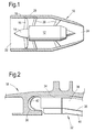
- FIG. 1 this shows schematically generally at 10 a turbofan aero engine comprising a core 12 which provides drive to a rotary fan 14 having a plurality of circumferentially spaced fan blades 16 thereabout.
- a nacelle surrounds the core 12 and is mounted thereon by struts 20.
- the nacelle has an inlet 22 and an exhaust nozzle 24 and forms a duct casing 18 around the fan 14.
- air is drawn in via the inlet 22 and compressed by the fan 14.
- Some of the compressed air is fed into the core 12 which includes further compressor stages, a combustor and a turbine which drives the fan 14 (none of which are shown).
- the rest of the air so called bypass air, is ducted around the outside of the core 12 and through the exhaust nozzle 24.
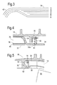
- Figure 2 shows in detailed sectional view a front, or forward portion of inner wall of the duct casing 18 in the region shown hatched in Figure 1 .
- the inner wall of the casing 18 defines a hook shaped arcuate recess 30 that is provided to accommodate a detached portion of fan blade (not shown) such as could be released in a fan blade off (FBO) event.
- FBO fan blade off
- FIG. 2 shows a front, or forward portion of the cassette which has a rigid tray backing portion 34 of composite ply material, an aluminium honeycomb layer 36, a septum 38 of glass fibre and a Nomex (RTM) honeycomb layer 40.
- the layers 36, 38 and 40 are bonded together and bonded to the tray 34.
- the front of the tray 34 has a resilient sprung section 42 which comprises a reduced number of plies and thus has reduced stiffness.
- the sprung section 42 wedges into the hook shape recess 30 and is held therein at its front edge.
- Figure 3 shows schematically the reduction of the number of plies of the tray 34 as it forms the sprung section 42.
- the shape of the forward sprung section 42 can be a simple e.g. circular, shape or else can be a more complex shape as is shown in the example of Figure 2 .
- the plies numbered 3-6 in the drawing are internal and are staggered before the curved sprung section 42. There can be an even or odd number of plies.
- the tray backing portion 34 has been described as being made of composite ply material, and this would typically comprise glass fibre or carbon fibre with an epoxy or similar matrix; although any other suitable composite material may be used. The skilled reader will understand, however, that other materials may be used for the tray backing portion 34, and in particular that it may be made from metal. In this case the reduced stiffness of the forward sprung section 42 could be achieved by, for example, using a reduced thickness of metal in this section.
- FIG. 4 shows a rear portion of the abradable liner panel 32.
- a rigid bracket 44 is mounted to a portion of the casing 18, and countersunk screws 46 pass through holes 34a in tray 34 and threadedly engage the bracket 44 to retain the tray in place.
- Springs 48 are positioned between the tray 34 and bracket 44, through which the screws pass. The springs 48 keep the tray 34 spaced from the bracket 44 at a position dictated by the screws 46. Locking nuts (not shown) may optionally be used to secure the screws on the bracket.
- the screw and spring arrangement at the rear of the panel 32 allows its position relative to the fan blade (not shown) to be adjusted. If the screws 46 are tightened the panel 32 moves away from the tip of the fan blade. If the screws 46 are loosened the clearance between the panel 32 and the tip of the fan blade becomes reduced.
- FIG. 5 shows an alternative embodiment in which the front of the panel is also adjustable.
- Screws 50 pass through holes 52 in the casing and slots (not shown) in the sprung section 42 of the tray 34 to engage threaded blocks 54 attached to the tray 34. Tightening of the screws 50 causes the sprung section 42 to become compressed which in turn has the effect of moving the panel 32 towards the tip of the fan blade, represented here at 56. Conversely, when the screws 50 are loosened, the sprung section 42 pushes the panel 32 further from the tip of the fan blade 56, thereby increasing the clearance between the two.
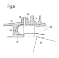
- FIG. 6 shows a further alternative embodiment. As with the embodiment of Figure 5 , this arrangement adjusts the clearance of the front of the panel 32 with respect to the fan blade 56.
- the screws 56 each pass through a boss 60 mounted on the fan case 18. A portion of the hole in the boss 60 is threaded with a locking insert (not shown) that prevents the screw 58 turning of its own accord. Tightening of the screws 58 causes them to push against the tray 34 which in turn forces the panel 32 to move towards the fan blade 56, compressing the sprung section 42. Conversely, loosening the screws 58 allows the sprung section 42 to push the panel 32 away from the tip of the blade 56 thereby increasing the clearance between the two.
- the above described systems for adjusting the front and rear of the panel may be combined, or may be employed separately, to provide liner panels which can be adjusted individually for optimum clearance from the tip of the fan blade.
- adjustable panels according to the present invention include minimising the requirement for inbuilt tolerances, which are needed conventionally for non-adjustable parts.
- the panels 32 are sprung, that is the FTL is resilient, and accordingly any debris from a collision, including an FBO event, can be absorbed by the springs/sprung sections, potentially deflecting the liner panel locally and thereby creating space for the debris to pass.
- This also allows for ice shedding provisions, in which the case liner must be able to withstand projectile ice, to be met with a lower-strength material which can be selected for better abrasion and/or sealing qualities.
Landscapes
- Engineering & Computer Science (AREA)
- Mechanical Engineering (AREA)
- General Engineering & Computer Science (AREA)
- Chemical & Material Sciences (AREA)
- Combustion & Propulsion (AREA)
- Structures Of Non-Positive Displacement Pumps (AREA)
Applications Claiming Priority (1)
| Application Number | Priority Date | Filing Date | Title |
|---|---|---|---|
| GBGB0914679.6A GB0914679D0 (en) | 2009-08-24 | 2009-08-24 | Adjustable fan case liner and mounting method |
Publications (2)
| Publication Number | Publication Date |
|---|---|
| EP2290196A2 true EP2290196A2 (de) | 2011-03-02 |
| EP2290196A3 EP2290196A3 (de) | 2017-12-06 |
Family
ID=41171766
Family Applications (1)
| Application Number | Title | Priority Date | Filing Date |
|---|---|---|---|
| EP10169974.2A Withdrawn EP2290196A3 (de) | 2009-08-24 | 2010-07-19 | Einstellbare Auskleidung eines Gebläsegehäuses und Einbauart |
Country Status (3)
| Country | Link |
|---|---|
| US (1) | US8636464B2 (de) |
| EP (1) | EP2290196A3 (de) |
| GB (1) | GB0914679D0 (de) |
Cited By (4)
| Publication number | Priority date | Publication date | Assignee | Title |
|---|---|---|---|---|
| WO2014137411A1 (en) * | 2013-03-04 | 2014-09-12 | Rolls-Royce Corporation | Fan track liner assembly with a spring element |
| WO2014143188A1 (en) * | 2013-03-11 | 2014-09-18 | Rolls-Royce Corporation | Fan track liner designed to yield next to fan case hook |
| EP2495402A3 (de) * | 2011-03-03 | 2015-02-25 | Rolls-Royce plc | Gebläsegehäuse für einen Turbogebläsemotor |
| US9598978B2 (en) | 2013-02-13 | 2017-03-21 | Rolls-Royce Plc | Fan containment system |
Families Citing this family (19)
| Publication number | Priority date | Publication date | Assignee | Title |
|---|---|---|---|---|
| US9249681B2 (en) | 2012-01-31 | 2016-02-02 | United Technologies Corporation | Fan case rub system |
| US9200531B2 (en) | 2012-01-31 | 2015-12-01 | United Technologies Corporation | Fan case rub system, components, and their manufacture |
| US9255489B2 (en) * | 2012-02-06 | 2016-02-09 | United Technologies Corporation | Clearance control for gas turbine engine section |
| US9228447B2 (en) | 2012-02-14 | 2016-01-05 | United Technologies Corporation | Adjustable blade outer air seal apparatus |
| US20140064938A1 (en) * | 2012-09-06 | 2014-03-06 | General Electric Company | Rub tolerant fan case |
| US9194299B2 (en) | 2012-12-21 | 2015-11-24 | United Technologies Corporation | Anti-torsion assembly |
| WO2014197053A2 (en) | 2013-03-13 | 2014-12-11 | United Technologies Corporation | Thermally conforming acoustic liner cartridge for a gas turbine engine |
| CN103522033B (zh) * | 2013-10-15 | 2016-08-03 | 成都发动机(集团)有限公司 | 发动机前传动机匣和后传动机匣的对接装配用工装 |
| US9822665B2 (en) * | 2013-12-05 | 2017-11-21 | United Technologies Corporation | Core drainage systems for fan case assemblies |
| GB2524229B (en) * | 2014-02-14 | 2016-02-24 | Rolls Royce Plc | Gas turbine engine |
| US10145301B2 (en) | 2014-09-23 | 2018-12-04 | Pratt & Whitney Canada Corp. | Gas turbine engine inlet |
| US10378554B2 (en) | 2014-09-23 | 2019-08-13 | Pratt & Whitney Canada Corp. | Gas turbine engine with partial inlet vane |
| US9957807B2 (en) | 2015-04-23 | 2018-05-01 | Pratt & Whitney Canada Corp. | Rotor assembly with scoop |
| US9938848B2 (en) * | 2015-04-23 | 2018-04-10 | Pratt & Whitney Canada Corp. | Rotor assembly with wear member |
| US10371173B2 (en) | 2015-05-07 | 2019-08-06 | United Technologies Corporation | Liner for a gas turbine engine |
| GB201600510D0 (en) * | 2016-01-12 | 2016-02-24 | Rolls Royce Plc And Rolls Royce Corp | Casing arrangement |
| US10260522B2 (en) | 2016-05-19 | 2019-04-16 | Rolls-Royce Corporation | Liner system |
| US10724540B2 (en) | 2016-12-06 | 2020-07-28 | Pratt & Whitney Canada Corp. | Stator for a gas turbine engine fan |
| US10690146B2 (en) | 2017-01-05 | 2020-06-23 | Pratt & Whitney Canada Corp. | Turbofan nacelle assembly with flow disruptor |
Citations (1)
| Publication number | Priority date | Publication date | Assignee | Title |
|---|---|---|---|---|
| EP1270876A2 (de) | 2001-06-18 | 2003-01-02 | General Electric Company | Federbelastete, abreibbare Dichtung für Turbomaschinen |
Family Cites Families (12)
| Publication number | Priority date | Publication date | Assignee | Title |
|---|---|---|---|---|
| GB869908A (en) | 1958-03-25 | 1961-06-07 | Zd Y V I Plzen | A packing device for the rotor blades of turbines |
| US5096375A (en) | 1989-09-08 | 1992-03-17 | General Electric Company | Radial adjustment mechanism for blade tip clearance control apparatus |
| US5056988A (en) * | 1990-02-12 | 1991-10-15 | General Electric Company | Blade tip clearance control apparatus using shroud segment position modulation |
| US5267828A (en) * | 1992-11-13 | 1993-12-07 | General Electric Company | Removable fan shroud panel |
| US5456576A (en) * | 1994-08-31 | 1995-10-10 | United Technologies Corporation | Dynamic control of tip clearance |
| US5599026A (en) * | 1995-09-06 | 1997-02-04 | Innovative Technology, L.L.C. | Turbine seal with sealing strip and rubbing strip |
| US6382905B1 (en) * | 2000-04-28 | 2002-05-07 | General Electric Company | Fan casing liner support |
| GB2418957B (en) * | 2003-10-22 | 2006-07-05 | Rolls Royce Plc | A liner for a gas turbine engine casing |
| GB2427436B (en) * | 2005-06-23 | 2007-11-28 | Rolls Royce Plc | Fan duct blade containment assembly |
| GB0513654D0 (en) * | 2005-07-02 | 2005-08-10 | Rolls Royce Plc | Variable displacement turbine liner |
| GB0610271D0 (en) * | 2006-05-24 | 2006-07-05 | Rolls Royce Plc | A gas turbine engine casing |
| GB2440744B (en) | 2006-08-09 | 2008-09-10 | Rolls Royce Plc | A blade clearance arrangement |
-
2009
- 2009-08-24 GB GBGB0914679.6A patent/GB0914679D0/en not_active Ceased
-
2010
- 2010-07-19 EP EP10169974.2A patent/EP2290196A3/de not_active Withdrawn
- 2010-07-19 US US12/838,752 patent/US8636464B2/en active Active
Patent Citations (1)
| Publication number | Priority date | Publication date | Assignee | Title |
|---|---|---|---|---|
| EP1270876A2 (de) | 2001-06-18 | 2003-01-02 | General Electric Company | Federbelastete, abreibbare Dichtung für Turbomaschinen |
Cited By (6)
| Publication number | Priority date | Publication date | Assignee | Title |
|---|---|---|---|---|
| EP2495402A3 (de) * | 2011-03-03 | 2015-02-25 | Rolls-Royce plc | Gebläsegehäuse für einen Turbogebläsemotor |
| US9598978B2 (en) | 2013-02-13 | 2017-03-21 | Rolls-Royce Plc | Fan containment system |
| EP2767676B1 (de) * | 2013-02-13 | 2017-09-20 | Rolls-Royce plc | Rückhaltesystem für Gebläse, zugehörige Gebläseanordnung und Gasturbinentriebwerk |
| WO2014137411A1 (en) * | 2013-03-04 | 2014-09-12 | Rolls-Royce Corporation | Fan track liner assembly with a spring element |
| WO2014143188A1 (en) * | 2013-03-11 | 2014-09-18 | Rolls-Royce Corporation | Fan track liner designed to yield next to fan case hook |
| US10024191B2 (en) | 2013-03-11 | 2018-07-17 | Rolls-Royce Corporation | Fan track liner designed to yield next to fan case hook |
Also Published As
| Publication number | Publication date |
|---|---|
| EP2290196A3 (de) | 2017-12-06 |
| US20110044807A1 (en) | 2011-02-24 |
| US8636464B2 (en) | 2014-01-28 |
| GB0914679D0 (en) | 2009-09-30 |
Similar Documents
| Publication | Publication Date | Title |
|---|---|---|
| US8636464B2 (en) | Adjustable fan case liner and mounting method | |
| US7866939B2 (en) | Liner for a gas turbine engine casing | |
| EP3246532B1 (de) | Auskleidungssystem für ein bläsergehäuse | |
| EP2767676B1 (de) | Rückhaltesystem für Gebläse, zugehörige Gebläseanordnung und Gasturbinentriebwerk | |
| US11168702B2 (en) | Rotating airfoil with tip pocket | |
| EP2927432B1 (de) | Gasturbinenmotor, verfahren zur herstellung eines gasturbinenmotors und bläsergehäuse | |
| US11008887B2 (en) | Fan containment assembly having a nesting cavity | |
| EP2458162A2 (de) | Berstschutzanordnung einer Gasturbine | |
| EP2952696B1 (de) | Turbofantriebwerksanordnung mit fangehäuse-auskleidungseinsatz | |
| EP3074605B1 (de) | Gebläseschaufel mit segmentierter ventilatorschaufelabdeckung | |
| EP2971660B1 (de) | Thermische anpassung einer schallauskleidungskartusche für einen gasturbinenmotor | |
| EP2902593B1 (de) | Fan-Rückhaltesystem in einem axialen Gasturbinentriebwerk | |
| US11118511B2 (en) | Fan blade containment system for gas turbine engine | |
| EP3640437B1 (de) | Gebläseschaufelrückhaltesystem, zugehöriges gasturbinentriebwerk und metallischer einsatz | |
| US20200123924A1 (en) | Debris retention | |
| US11753967B2 (en) | Fan case assembly for a gas turbine engine | |
| EP3546706B1 (de) | Gehäuseanordnung | |
| US20210054762A1 (en) | Gas turbine engine fan bumper | |
| US20230193827A1 (en) | Fan case assembly for a gas turbine engine |
Legal Events
| Date | Code | Title | Description |
|---|---|---|---|
| PUAI | Public reference made under article 153(3) epc to a published international application that has entered the european phase |
Free format text: ORIGINAL CODE: 0009012 |
|
| AK | Designated contracting states |
Kind code of ref document: A2 Designated state(s): AL AT BE BG CH CY CZ DE DK EE ES FI FR GB GR HR HU IE IS IT LI LT LU LV MC MK MT NL NO PL PT RO SE SI SK SM TR |
|
| AX | Request for extension of the european patent |
Extension state: BA ME RS |
|
| RAP1 | Party data changed (applicant data changed or rights of an application transferred) |
Owner name: ROLLS-ROYCE PLC |
|
| PUAL | Search report despatched |
Free format text: ORIGINAL CODE: 0009013 |
|
| AK | Designated contracting states |
Kind code of ref document: A3 Designated state(s): AL AT BE BG CH CY CZ DE DK EE ES FI FR GB GR HR HU IE IS IT LI LT LU LV MC MK MT NL NO PL PT RO SE SI SK SM TR |
|
| AX | Request for extension of the european patent |
Extension state: BA ME RS |
|
| RIC1 | Information provided on ipc code assigned before grant |
Ipc: F02K 3/06 20060101ALI20171030BHEP Ipc: F01D 11/08 20060101AFI20171030BHEP |
|
| STAA | Information on the status of an ep patent application or granted ep patent |
Free format text: STATUS: THE APPLICATION HAS BEEN PUBLISHED |
|
| STAA | Information on the status of an ep patent application or granted ep patent |
Free format text: STATUS: THE APPLICATION IS DEEMED TO BE WITHDRAWN |
|
| 18D | Application deemed to be withdrawn |
Effective date: 20180607 |