EP2290263A2 - Procédé de synchronisation, servomoteur et dispositif de couplage doté d'un servomoteur - Google Patents
Procédé de synchronisation, servomoteur et dispositif de couplage doté d'un servomoteur Download PDFInfo
- Publication number
- EP2290263A2 EP2290263A2 EP10169469A EP10169469A EP2290263A2 EP 2290263 A2 EP2290263 A2 EP 2290263A2 EP 10169469 A EP10169469 A EP 10169469A EP 10169469 A EP10169469 A EP 10169469A EP 2290263 A2 EP2290263 A2 EP 2290263A2
- Authority
- EP
- European Patent Office
- Prior art keywords
- piston
- switching
- phase
- der
- servo motor
- Prior art date
- Legal status (The legal status is an assumption and is not a legal conclusion. Google has not performed a legal analysis and makes no representation as to the accuracy of the status listed.)
- Granted
Links
- 238000000034 method Methods 0.000 title claims abstract description 19
- 230000005540 biological transmission Effects 0.000 claims description 14
- 238000013016 damping Methods 0.000 claims description 12
- 230000001360 synchronised effect Effects 0.000 claims description 7
- 238000007789 sealing Methods 0.000 claims description 2
- 230000000903 blocking effect Effects 0.000 claims 1
- 230000008878 coupling Effects 0.000 description 13
- 238000010168 coupling process Methods 0.000 description 13
- 238000005859 coupling reaction Methods 0.000 description 13
- 230000008569 process Effects 0.000 description 9
- 230000008901 benefit Effects 0.000 description 5
- 238000010586 diagram Methods 0.000 description 4
- 238000006073 displacement reaction Methods 0.000 description 4
- 238000000418 atomic force spectrum Methods 0.000 description 2
- 208000032370 Secondary transmission Diseases 0.000 description 1
- 230000008859 change Effects 0.000 description 1
- 238000004891 communication Methods 0.000 description 1
- 230000000694 effects Effects 0.000 description 1
- 230000009347 mechanical transmission Effects 0.000 description 1
- 230000007246 mechanism Effects 0.000 description 1
- 230000001960 triggered effect Effects 0.000 description 1
- 238000011144 upstream manufacturing Methods 0.000 description 1
Images



Classifications
-
- F—MECHANICAL ENGINEERING; LIGHTING; HEATING; WEAPONS; BLASTING
- F15—FLUID-PRESSURE ACTUATORS; HYDRAULICS OR PNEUMATICS IN GENERAL
- F15B—SYSTEMS ACTING BY MEANS OF FLUIDS IN GENERAL; FLUID-PRESSURE ACTUATORS, e.g. SERVOMOTORS; DETAILS OF FLUID-PRESSURE SYSTEMS, NOT OTHERWISE PROVIDED FOR
- F15B11/00—Servomotor systems without provision for follow-up action; Circuits therefor
- F15B11/02—Systems essentially incorporating special features for controlling the speed or actuating force of an output member
- F15B11/028—Systems essentially incorporating special features for controlling the speed or actuating force of an output member for controlling the actuating force
-
- F—MECHANICAL ENGINEERING; LIGHTING; HEATING; WEAPONS; BLASTING
- F15—FLUID-PRESSURE ACTUATORS; HYDRAULICS OR PNEUMATICS IN GENERAL
- F15B—SYSTEMS ACTING BY MEANS OF FLUIDS IN GENERAL; FLUID-PRESSURE ACTUATORS, e.g. SERVOMOTORS; DETAILS OF FLUID-PRESSURE SYSTEMS, NOT OTHERWISE PROVIDED FOR
- F15B15/00—Fluid-actuated devices for displacing a member from one position to another; Gearing associated therewith
- F15B15/08—Characterised by the construction of the motor unit
- F15B15/14—Characterised by the construction of the motor unit of the straight-cylinder type
- F15B15/1423—Component parts; Constructional details
- F15B15/1447—Pistons; Piston to piston rod assemblies
-
- F—MECHANICAL ENGINEERING; LIGHTING; HEATING; WEAPONS; BLASTING
- F16—ENGINEERING ELEMENTS AND UNITS; GENERAL MEASURES FOR PRODUCING AND MAINTAINING EFFECTIVE FUNCTIONING OF MACHINES OR INSTALLATIONS; THERMAL INSULATION IN GENERAL
- F16H—GEARING
- F16H61/00—Control functions within control units of change-speed- or reversing-gearings for conveying rotary motion ; Control of exclusively fluid gearing, friction gearing, gearings with endless flexible members or other particular types of gearing
- F16H61/26—Generation or transmission of movements for final actuating mechanisms
- F16H61/28—Generation or transmission of movements for final actuating mechanisms with at least one movement of the final actuating mechanism being caused by a non-mechanical force, e.g. power-assisted
- F16H61/30—Hydraulic or pneumatic motors or related fluid control means therefor
-
- F—MECHANICAL ENGINEERING; LIGHTING; HEATING; WEAPONS; BLASTING
- F16—ENGINEERING ELEMENTS AND UNITS; GENERAL MEASURES FOR PRODUCING AND MAINTAINING EFFECTIVE FUNCTIONING OF MACHINES OR INSTALLATIONS; THERMAL INSULATION IN GENERAL
- F16H—GEARING
- F16H61/00—Control functions within control units of change-speed- or reversing-gearings for conveying rotary motion ; Control of exclusively fluid gearing, friction gearing, gearings with endless flexible members or other particular types of gearing
- F16H61/26—Generation or transmission of movements for final actuating mechanisms
- F16H61/28—Generation or transmission of movements for final actuating mechanisms with at least one movement of the final actuating mechanism being caused by a non-mechanical force, e.g. power-assisted
- F16H2061/2823—Controlling actuator force way characteristic, i.e. controlling force or movement depending on the actuator position, e.g. for adapting force to synchronisation and engagement of gear clutch
-
- F—MECHANICAL ENGINEERING; LIGHTING; HEATING; WEAPONS; BLASTING
- F16—ENGINEERING ELEMENTS AND UNITS; GENERAL MEASURES FOR PRODUCING AND MAINTAINING EFFECTIVE FUNCTIONING OF MACHINES OR INSTALLATIONS; THERMAL INSULATION IN GENERAL
- F16H—GEARING
- F16H61/00—Control functions within control units of change-speed- or reversing-gearings for conveying rotary motion ; Control of exclusively fluid gearing, friction gearing, gearings with endless flexible members or other particular types of gearing
- F16H61/26—Generation or transmission of movements for final actuating mechanisms
- F16H61/28—Generation or transmission of movements for final actuating mechanisms with at least one movement of the final actuating mechanism being caused by a non-mechanical force, e.g. power-assisted
- F16H61/30—Hydraulic or pneumatic motors or related fluid control means therefor
- F16H2061/307—Actuators with three or more defined positions, e.g. three position servos
-
- F—MECHANICAL ENGINEERING; LIGHTING; HEATING; WEAPONS; BLASTING
- F16—ENGINEERING ELEMENTS AND UNITS; GENERAL MEASURES FOR PRODUCING AND MAINTAINING EFFECTIVE FUNCTIONING OF MACHINES OR INSTALLATIONS; THERMAL INSULATION IN GENERAL
- F16H—GEARING
- F16H61/00—Control functions within control units of change-speed- or reversing-gearings for conveying rotary motion ; Control of exclusively fluid gearing, friction gearing, gearings with endless flexible members or other particular types of gearing
- F16H61/70—Control functions within control units of change-speed- or reversing-gearings for conveying rotary motion ; Control of exclusively fluid gearing, friction gearing, gearings with endless flexible members or other particular types of gearing specially adapted for change-speed gearing in group arrangement, i.e. with separate change-speed gear trains arranged in series, e.g. range or overdrive-type gearing arrangements
- F16H61/705—Control functions within control units of change-speed- or reversing-gearings for conveying rotary motion ; Control of exclusively fluid gearing, friction gearing, gearings with endless flexible members or other particular types of gearing specially adapted for change-speed gearing in group arrangement, i.e. with separate change-speed gear trains arranged in series, e.g. range or overdrive-type gearing arrangements using hydraulic and mechanical control means
Definitions
- the invention relates to a method for carrying out a synchronized switching operation according to the preamble of claim 1, a servomotor according to the preamble of claim 4 and a switching device for switching of group transmissions according to the preamble of claim 11.
- z. B. form as a three- or two-group transmission.
- a main gearbox is assigned a ballast split group and / or a rear-end range group.
- the splitter group is used to compact the gear sequence and the range or range group to extend the gear sequence.
- the connection of the upstream or rear group can be triggered by the driver or automatically, d. H. be carried out using electro-pneumatic, electro-hydraulic or electro-mechanical actuators or servomotors. In commercial vehicles mainly pneumatic actuators are used.
- the applicant has been known a pneumatic switching device for a group circuit of a mechanical transmission in a motor vehicle.
- the switching device comprises a pneumatic cylinder in which a piston is slidably disposed with a piston rod, wherein the piston rod is connected to a switching mechanism.
- a problem of the known pneumatic actuating cylinder, also called servo motor consists in the hard impact of the piston and the sliding sleeve synchronization when reaching the end positions, which leads to undesirable impact noise and material wear. It has therefore already made various proposals for cushioning the pneumatic piston.
- a longitudinally movable slide is arranged in the switching piston, which opens a flow channel in the piston before reaching the end position, so that a pressure equalization takes place on both sides of the piston. This achieves a damping effect.
- a pneumatic actuator for switching a step change gear for motor vehicles has been known.
- a main piston with a piston rod and an auxiliary piston are arranged in a cylinder housing, which is slidably disposed on the piston rod and performs a partial stroke in the cylinder housing.
- the switching movement is divided into a fast and a slow movement by means of the auxiliary piston, which has a throttle bore.
- the auxiliary piston meets after passing through the partial stroke to a stop, then the air flows throttled into the space between the auxiliary piston and the main piston, so that a two-stage switching sequence is generated.
- the invention it is provided in the method that during the first phase of the switching operation, a relatively high switching force acts, while in the subsequent second phase, a relatively low switching force is exerted.
- a relatively high switching force acts, while in the subsequent second phase, a relatively low switching force is exerted.
- the switching process takes place substantially in two phases, wherein the first phase comprises the synchronization and locking, which is known to require a higher switching force.
- the second phase d. H. when the synchronization is completed and the locking by the locking teeth of the synchronizer ring is canceled, the switching through, d. H.
- the shift sleeve is pushed with its gear teeth on the teeth of the coupling body and thus establishes the positive connection - this sliding, which completes the entire shift, requires a lower switching force.
- the process of the invention takes into account, at the same time the advantage is achieved that due to the lower switching force in the second phase, a softer stop occurs in the end positions, in addition, a damping by damping elements is advantageous. The shifting comfort is thus significantly improved.
- the switching force is constant during the first phase, preferably also in the second phase, the drop in the switching force preferably taking place abruptly (in a step function).
- This functional curve of the switching force over the path of the sliding sleeve is optimally adapted to the synchronized switching process.
- a shared piston is provided in a servomotor, which has an annular outer piston and an inner piston which is connected to the piston rod.
- the inner piston is slidably disposed in the outer piston and limited in its axial displacement by stops. Because the outer piston has a larger outer diameter and a larger one has effective piston area than the inner piston is transmitted by the outer piston, a larger actuating force via the piston rod.
- annular stop surfaces are preferably provided on the end faces of the cylinder, which limit the stroke of the annular piston.
- the servomotor according to the invention thus offers the advantage that initially a relatively high first actuating force is exerted via a specific first path (piston stroke), while subsequently a lower actuating force is generated via a second path (piston stroke).
- the servomotor is designed as a pneumatic cylinder, d. H.
- compressed air is used, which is available in particular in commercial vehicles.
- a control motor of the aforementioned type and with the aforementioned features is provided in a switching device for synchronized switching of group transmissions.
- the advantage is achieved that the course of the switching force is adapted to the shift sleeve the synchronization and switching operation.
- the shifting comfort is improved, in particular fewer noise and less wear are caused because of the lower switching force in the second phase of the switching process.
- different forces occur during synchronized switching on the sliding sleeve, ie. H. in the phase of synchronizing and locking occurs on the sliding sleeve a greater switching force than in the phase of sliding over the shift sleeve on the coupling body when the positive connection is made.
- the inventive design of the servomotor is adjusted.
- the synchronizer is designed as Einkonus synchronization.
- the servo motor according to the invention is also suitable for other types used by synchronizers, so for example Doppelkonus- or locking pin synchronizers.
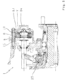
- Fig. 1 shows a partially illustrated switching device 1 of a group transmission, which is particularly useful for commercial vehicles.
- the switching device 1 comprises a trained as a pneumatic cylinder servo motor 2, a shift rod 3, a rocker arm 4 and a synchronizer 5.
- a partially illustrated, preferably designed as a planetary gear secondary transmission is switched by means of the servo motor 2, creating a fast and a slow translation is achieved.
- the servo motor 2 has a pressure cylinder 6, which is attached to a transmission housing 7 and sealed.
- an annular outer piston 8, hereinafter also referred to as ring piston 8 is arranged in a sliding manner.
- an inner piston 9 is slidably disposed, which is fixedly connected to a piston rod 10 which simultaneously forms the shift rod 3.
- the inner piston 9 forms with the annular piston 8 a sliding fit (without reference number), which is sealed by sealing elements, preferably O-rings 11 or piston seals.
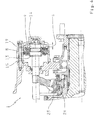
- the inner piston 9 can perform an additional stroke s relative to the annular piston 8; the lifting movement of the inner piston 9 is limited by axial stop elements in the form of stop plates 12, 13 or circular stops.
- the Cylinder 6 forms with the transmission housing 7 a closed pressure chamber which is subdivided by the pistons 8, 9 into the variable volumes or spaces 14, 15.
- the spaces 14, 15 are - depending on the direction of movement of the piston rod 10 - alternately pressurized or vented.
- the synchronizing device 5 is known per se from the structure and from the function (cf. H. Naunheimer, B. Bertsche u. G. Lechner, vehicle transmission, 2nd edition, 2007, page 318-320 ): It is a one-cone synchronization, which comprises the following parts: a synchronizer body 20, a first synchronizer ring 21, a second synchronizer ring 22, a shift sleeve 23 and a first clutch body 24 and a second clutch body 25. Die GmbHmuffe 23 auf auf known manner shifted by the shift rocker 4, wherein the direction of displacement of the shift sleeve 23 opposite to the direction of displacement of the shift rod 3 and the piston rod 10 is.
- the synchronizer body 20 is rotatably connected to a hollow shaft 26; the second clutch body 25 is rotatably mounted on a shaft 27 which is mounted in the transmission housing 7.
- the lower part of the diagram shows the switching force curve in a circuit of the downstream group transmission in an opposite second translation.
- the direction of movement according to the arrows 32, 33 in the reverse direction also at initially constant switching force F3 at an exemplary value of about -7.5 kN to the point P3.
- point P3 which is the representation in Fig. 3 corresponds
- the annular piston 8 is in the end position, the synchronization process is completed.
- the lower switching force F4 is effected by the stroke of the inner piston 9.
- the different switching forces F1 or F3 and F2 or F4 in the two switching directions are caused by the piston rod 10, which reduces the effective pressure surface on the annular piston 8 and inner piston 9 on one side.
Landscapes
- Engineering & Computer Science (AREA)
- General Engineering & Computer Science (AREA)
- Mechanical Engineering (AREA)
- Physics & Mathematics (AREA)
- Fluid Mechanics (AREA)
- Gear-Shifting Mechanisms (AREA)
- Manufacture Of Motors, Generators (AREA)
Applications Claiming Priority (1)
| Application Number | Priority Date | Filing Date | Title |
|---|---|---|---|
| DE200910029038 DE102009029038A1 (de) | 2009-08-31 | 2009-08-31 | Verfahren zur Synchronisierung, Stellmotor und Schalteinrichtung mit Stellmotor |
Publications (3)
| Publication Number | Publication Date |
|---|---|
| EP2290263A2 true EP2290263A2 (fr) | 2011-03-02 |
| EP2290263A3 EP2290263A3 (fr) | 2011-04-13 |
| EP2290263B1 EP2290263B1 (fr) | 2012-09-12 |
Family
ID=42791042
Family Applications (1)
| Application Number | Title | Priority Date | Filing Date |
|---|---|---|---|
| EP20100169469 Not-in-force EP2290263B1 (fr) | 2009-08-31 | 2010-07-14 | Servomoteur |
Country Status (2)
| Country | Link |
|---|---|
| EP (1) | EP2290263B1 (fr) |
| DE (1) | DE102009029038A1 (fr) |
Cited By (1)
| Publication number | Priority date | Publication date | Assignee | Title |
|---|---|---|---|---|
| WO2018137896A1 (fr) * | 2017-01-30 | 2018-08-02 | Zf Friedrichshafen Ag | Actionneur de passage de vitesse, blocage de différentiel, boîte de transfert, boîte de vitesses manuelle et raccordement d'essieu |
Families Citing this family (3)
| Publication number | Priority date | Publication date | Assignee | Title |
|---|---|---|---|---|
| DE102017003017A1 (de) | 2017-03-29 | 2018-10-04 | Wabco Gmbh | Aktuator für ein automatisiertes oder automatisches Schaltgetriebe und Verfahren zur Steuerung dieses Aktuators |
| CN110206880B (zh) * | 2019-04-17 | 2020-02-18 | 东风商用车有限公司 | 一种延长商用车变速箱同步器使用寿命的方法 |
| DE102020216238A1 (de) | 2020-12-18 | 2022-06-23 | Zf Friedrichshafen Ag | Betätigungszylindermodul für ein Fahrzeuggetriebe und Fahrzeuggetriebe |
Citations (3)
| Publication number | Priority date | Publication date | Assignee | Title |
|---|---|---|---|---|
| DE1155348B (de) | 1958-11-13 | 1963-10-03 | Tatra Np | Pneumatische Betaetigungsvorrichtung zum Umschalten eines Stufenwechselgetriebes, insbesondere fuer Kraftfahrzeuge |
| WO1990003523A1 (fr) | 1988-09-23 | 1990-04-05 | Zahnradfabrik Friedrichshafen Ag | Dispositif d'amortissement de fin de course |
| DE19543646A1 (de) | 1995-11-23 | 1997-05-28 | Zahnradfabrik Friedrichshafen | Schalteinrichtung |
Family Cites Families (16)
| Publication number | Priority date | Publication date | Assignee | Title |
|---|---|---|---|---|
| DE1576175B1 (de) * | 1966-11-15 | 1971-12-23 | Barkas Werke Veb | Druckmittelbetaetigter Arbeitszylinder mit zweiseitiger Beaufschlagung,insbesondere fuer die Schaltung von Getrieben fuer Motorfahrzeuge |
| CS151966B1 (fr) * | 1970-07-10 | 1973-12-19 | ||
| GB1399370A (en) * | 1972-09-08 | 1975-07-02 | Ford Motor Co | Motor vehicle layshaft gearbox |
| DE3107908A1 (de) * | 1981-03-02 | 1982-09-16 | Leibfried Maschinenbau Gmbh, 7033 Herrenberg | Kolben-zylinder-aggregat |
| DE3329801A1 (de) * | 1983-08-18 | 1985-02-28 | Wabco Westinghouse Fahrzeugbremsen GmbH, 3000 Hannover | Synchronisiertes getriebe |
| DE3336682A1 (de) * | 1983-10-08 | 1985-04-25 | Wabco Westinghouse Fahrzeugbremsen GmbH, 3000 Hannover | Arbeitszylinder mit drei stellungen |
| DE3337969A1 (de) * | 1983-10-19 | 1985-05-02 | Wabco Westinghouse Fahrzeugbremsen GmbH, 3000 Hannover | Arbeitszylinder mit drei stellungen |
| IT1219353B (it) * | 1988-05-31 | 1990-05-11 | Fiatgeotech | Attuatore a comando tramite fluido |
| US4928544A (en) * | 1989-06-19 | 1990-05-29 | Eaton Corporation | Dual pressure pressurized fluid actuated shifting mechanism |
| DE4128389A1 (de) * | 1991-08-27 | 1993-03-04 | Grau Gmbh | Doppelt wirkender betaetigungszylinder |
| DE19939204B4 (de) * | 1999-08-18 | 2012-09-20 | Dr. Ing. H.C. F. Porsche Aktiengesellschaft | Gangschalteinrichtung für ein synchronisiertes Wechselgetriebe |
| DE10131853A1 (de) * | 2001-06-30 | 2003-01-23 | Wabco Gmbh & Co Ohg | Verfahren zur Ermittlung des Betätigungsdrucks eines druckmittelbetätigten Stellzylinders |
| WO2003081091A2 (fr) * | 2002-03-21 | 2003-10-02 | Luk Lamellen Und Kupplungsbau Beteiligungs Kg | Dispositif d'actionnement de boite de vitesse et procede de synchronisation pour boite de vitesses |
| JP2004138131A (ja) * | 2002-10-17 | 2004-05-13 | Hitachi Ltd | 自動車のパワートレーンにおけるシンクロ機構の操作装置 |
| GB0307117D0 (en) * | 2003-03-27 | 2003-04-30 | Ricardo Uk Linmited | Method for controlling a transmission of a vehicle |
| DE102004006625A1 (de) * | 2004-02-10 | 2005-09-08 | Volkswagen Ag | Betätigungsvorrichtung zur direkten und/oder indirekten Bewegung bzw. Verstellung von Schaltschienen und/oder Schaltwellen eines Getriebes |
-
2009
- 2009-08-31 DE DE200910029038 patent/DE102009029038A1/de not_active Withdrawn
-
2010
- 2010-07-14 EP EP20100169469 patent/EP2290263B1/fr not_active Not-in-force
Patent Citations (3)
| Publication number | Priority date | Publication date | Assignee | Title |
|---|---|---|---|---|
| DE1155348B (de) | 1958-11-13 | 1963-10-03 | Tatra Np | Pneumatische Betaetigungsvorrichtung zum Umschalten eines Stufenwechselgetriebes, insbesondere fuer Kraftfahrzeuge |
| WO1990003523A1 (fr) | 1988-09-23 | 1990-04-05 | Zahnradfabrik Friedrichshafen Ag | Dispositif d'amortissement de fin de course |
| DE19543646A1 (de) | 1995-11-23 | 1997-05-28 | Zahnradfabrik Friedrichshafen | Schalteinrichtung |
Cited By (2)
| Publication number | Priority date | Publication date | Assignee | Title |
|---|---|---|---|---|
| WO2018137896A1 (fr) * | 2017-01-30 | 2018-08-02 | Zf Friedrichshafen Ag | Actionneur de passage de vitesse, blocage de différentiel, boîte de transfert, boîte de vitesses manuelle et raccordement d'essieu |
| US11408497B2 (en) | 2017-01-30 | 2022-08-09 | Zf Friedrichshafen Ag | Shift actuators, differential lock, distributor gearbox, shift gearbox and axle connection |
Also Published As
| Publication number | Publication date |
|---|---|
| EP2290263A3 (fr) | 2011-04-13 |
| DE102009029038A1 (de) | 2011-03-03 |
| EP2290263B1 (fr) | 2012-09-12 |
Similar Documents
| Publication | Publication Date | Title |
|---|---|---|
| EP3058250B1 (fr) | Dispositif de commande hydraulique pour transmission automatique | |
| DE102009014502B4 (de) | Hydraulischer Aktor für Getriebe mit verringertem Geräusch | |
| DE2512206A1 (de) | Geschwindigkeitswechselgetriebe | |
| DE3147003C2 (de) | Mechanische Gangschalteinrichtung | |
| DE102019203255A1 (de) | Klauenkupplung zum formschlüssigen Verbinden eines ersten drehbaren Bauteiles mit einem zweiten drehbaren Bauteil | |
| EP3253982A1 (fr) | Dispositif d'actionnement d'un embrayage et procédé d'actionnement dudit dispositif | |
| EP2290263B1 (fr) | Servomoteur | |
| DE10331370A1 (de) | Automatgetriebe mit einem hydraulisch betätigbaren Schaltglied | |
| DE2062873B2 (de) | Servomotor zum betaetigen eines reibungsschaltmittels eines kraftfahrzeugwechselgetriebes | |
| DE102006023648B4 (de) | Anpressvorrichtung für ein Kegelringgetriebe | |
| WO2018077462A1 (fr) | Cylindre de commande d'une boîte de vitesses automatique | |
| DE19957272A1 (de) | Kraftfahrzeug | |
| DE102006035938B4 (de) | Getriebestellvorrichtung mit einem Stellzylinder | |
| EP1753985B1 (fr) | Entrainement lineaire hydraulique, en particulier actionneur de transmission hydraulique | |
| DE102021126110B3 (de) | Drehmomentverteileinrichtung und Verfahren zum Betrieb einer Drehmomentverteileinrichtung | |
| WO2020088888A1 (fr) | Dispositif d'assistance par asservissement, en particulier pour une boîte de vitesses de véhicule automobile | |
| DE3329801C2 (fr) | ||
| EP1477711B1 (fr) | Dispositif de changement de vitesse | |
| DE102019202617B4 (de) | Schaltelement für ein Automatikgetriebe und Verfahren zu dessen Betätigung | |
| DE1225052B (de) | Servosteuereinrichtung fuer druckmittelbeaufschlagte Kolben | |
| DE102008043494A1 (de) | Hydraulischer Stellantrieb | |
| DE102018107988B4 (de) | Betätigungsvorrichtung für ein Schaltgetriebe | |
| DE102004037116A1 (de) | Hydraulischer Linearantrieb, insbesondere hydraulischer Getriebeaktuator | |
| DE19608856C2 (de) | Hydraulischer Lehneneinsteller | |
| DE102022108361A1 (de) | Schaltvorrichtung für ein Schaltgetriebe eines Fahrzeugs |
Legal Events
| Date | Code | Title | Description |
|---|---|---|---|
| PUAI | Public reference made under article 153(3) epc to a published international application that has entered the european phase |
Free format text: ORIGINAL CODE: 0009012 |
|
| AK | Designated contracting states |
Kind code of ref document: A2 Designated state(s): AL AT BE BG CH CY CZ DE DK EE ES FI FR GB GR HR HU IE IS IT LI LT LU LV MC MK MT NL NO PL PT RO SE SI SK SM TR |
|
| AX | Request for extension of the european patent |
Extension state: BA ME RS |
|
| PUAL | Search report despatched |
Free format text: ORIGINAL CODE: 0009013 |
|
| AK | Designated contracting states |
Kind code of ref document: A3 Designated state(s): AL AT BE BG CH CY CZ DE DK EE ES FI FR GB GR HR HU IE IS IT LI LT LU LV MC MK MT NL NO PL PT RO SE SI SK SM TR |
|
| AX | Request for extension of the european patent |
Extension state: BA ME RS |
|
| RIC1 | Information provided on ipc code assigned before grant |
Ipc: F15B 11/12 20060101ALI20110308BHEP Ipc: F16H 61/30 20060101ALN20101019BHEP Ipc: F16H 61/28 20060101AFI20101019BHEP |
|
| 17P | Request for examination filed |
Effective date: 20111013 |
|
| 17Q | First examination report despatched |
Effective date: 20111201 |
|
| RIC1 | Information provided on ipc code assigned before grant |
Ipc: F16H 61/28 20060101AFI20120222BHEP Ipc: F15B 11/12 20060101ALI20120222BHEP Ipc: F16H 61/30 20060101ALN20120222BHEP |
|
| RTI1 | Title (correction) |
Free format text: ACTUATOR |
|
| GRAP | Despatch of communication of intention to grant a patent |
Free format text: ORIGINAL CODE: EPIDOSNIGR1 |
|
| RIC1 | Information provided on ipc code assigned before grant |
Ipc: F16H 61/30 20060101ALN20120319BHEP Ipc: F15B 11/12 20060101ALI20120319BHEP Ipc: F16H 61/28 20060101AFI20120319BHEP |
|
| GRAS | Grant fee paid |
Free format text: ORIGINAL CODE: EPIDOSNIGR3 |
|
| GRAA | (expected) grant |
Free format text: ORIGINAL CODE: 0009210 |
|
| AK | Designated contracting states |
Kind code of ref document: B1 Designated state(s): AL AT BE BG CH CY CZ DE DK EE ES FI FR GB GR HR HU IE IS IT LI LT LU LV MC MK MT NL NO PL PT RO SE SI SK SM TR |
|
| REG | Reference to a national code |
Ref country code: GB Ref legal event code: FG4D Free format text: NOT ENGLISH |
|
| REG | Reference to a national code |
Ref country code: CH Ref legal event code: EP |
|
| REG | Reference to a national code |
Ref country code: AT Ref legal event code: REF Ref document number: 575258 Country of ref document: AT Kind code of ref document: T Effective date: 20120915 |
|
| REG | Reference to a national code |
Ref country code: IE Ref legal event code: FG4D Free format text: LANGUAGE OF EP DOCUMENT: GERMAN |
|
| REG | Reference to a national code |
Ref country code: DE Ref legal event code: R096 Ref document number: 502010001247 Country of ref document: DE Effective date: 20121108 |
|
| REG | Reference to a national code |
Ref country code: SE Ref legal event code: TRGR |
|
| PG25 | Lapsed in a contracting state [announced via postgrant information from national office to epo] |
Ref country code: NO Free format text: LAPSE BECAUSE OF FAILURE TO SUBMIT A TRANSLATION OF THE DESCRIPTION OR TO PAY THE FEE WITHIN THE PRESCRIBED TIME-LIMIT Effective date: 20121212 Ref country code: FI Free format text: LAPSE BECAUSE OF FAILURE TO SUBMIT A TRANSLATION OF THE DESCRIPTION OR TO PAY THE FEE WITHIN THE PRESCRIBED TIME-LIMIT Effective date: 20120912 Ref country code: LT Free format text: LAPSE BECAUSE OF FAILURE TO SUBMIT A TRANSLATION OF THE DESCRIPTION OR TO PAY THE FEE WITHIN THE PRESCRIBED TIME-LIMIT Effective date: 20120912 Ref country code: HR Free format text: LAPSE BECAUSE OF FAILURE TO SUBMIT A TRANSLATION OF THE DESCRIPTION OR TO PAY THE FEE WITHIN THE PRESCRIBED TIME-LIMIT Effective date: 20120912 |
|
| REG | Reference to a national code |
Ref country code: NL Ref legal event code: VDEP Effective date: 20120912 |
|
| REG | Reference to a national code |
Ref country code: LT Ref legal event code: MG4D Effective date: 20120912 |
|
| PG25 | Lapsed in a contracting state [announced via postgrant information from national office to epo] |
Ref country code: LV Free format text: LAPSE BECAUSE OF FAILURE TO SUBMIT A TRANSLATION OF THE DESCRIPTION OR TO PAY THE FEE WITHIN THE PRESCRIBED TIME-LIMIT Effective date: 20120912 Ref country code: GR Free format text: LAPSE BECAUSE OF FAILURE TO SUBMIT A TRANSLATION OF THE DESCRIPTION OR TO PAY THE FEE WITHIN THE PRESCRIBED TIME-LIMIT Effective date: 20121213 Ref country code: SI Free format text: LAPSE BECAUSE OF FAILURE TO SUBMIT A TRANSLATION OF THE DESCRIPTION OR TO PAY THE FEE WITHIN THE PRESCRIBED TIME-LIMIT Effective date: 20120912 |
|
| PG25 | Lapsed in a contracting state [announced via postgrant information from national office to epo] |
Ref country code: CZ Free format text: LAPSE BECAUSE OF FAILURE TO SUBMIT A TRANSLATION OF THE DESCRIPTION OR TO PAY THE FEE WITHIN THE PRESCRIBED TIME-LIMIT Effective date: 20120912 Ref country code: NL Free format text: LAPSE BECAUSE OF FAILURE TO SUBMIT A TRANSLATION OF THE DESCRIPTION OR TO PAY THE FEE WITHIN THE PRESCRIBED TIME-LIMIT Effective date: 20120912 Ref country code: IS Free format text: LAPSE BECAUSE OF FAILURE TO SUBMIT A TRANSLATION OF THE DESCRIPTION OR TO PAY THE FEE WITHIN THE PRESCRIBED TIME-LIMIT Effective date: 20130112 Ref country code: RO Free format text: LAPSE BECAUSE OF FAILURE TO SUBMIT A TRANSLATION OF THE DESCRIPTION OR TO PAY THE FEE WITHIN THE PRESCRIBED TIME-LIMIT Effective date: 20120912 Ref country code: EE Free format text: LAPSE BECAUSE OF FAILURE TO SUBMIT A TRANSLATION OF THE DESCRIPTION OR TO PAY THE FEE WITHIN THE PRESCRIBED TIME-LIMIT Effective date: 20120912 Ref country code: ES Free format text: LAPSE BECAUSE OF FAILURE TO SUBMIT A TRANSLATION OF THE DESCRIPTION OR TO PAY THE FEE WITHIN THE PRESCRIBED TIME-LIMIT Effective date: 20121223 |
|
| PG25 | Lapsed in a contracting state [announced via postgrant information from national office to epo] |
Ref country code: PL Free format text: LAPSE BECAUSE OF FAILURE TO SUBMIT A TRANSLATION OF THE DESCRIPTION OR TO PAY THE FEE WITHIN THE PRESCRIBED TIME-LIMIT Effective date: 20120912 Ref country code: SK Free format text: LAPSE BECAUSE OF FAILURE TO SUBMIT A TRANSLATION OF THE DESCRIPTION OR TO PAY THE FEE WITHIN THE PRESCRIBED TIME-LIMIT Effective date: 20120912 Ref country code: PT Free format text: LAPSE BECAUSE OF FAILURE TO SUBMIT A TRANSLATION OF THE DESCRIPTION OR TO PAY THE FEE WITHIN THE PRESCRIBED TIME-LIMIT Effective date: 20130114 |
|
| PLBE | No opposition filed within time limit |
Free format text: ORIGINAL CODE: 0009261 |
|
| STAA | Information on the status of an ep patent application or granted ep patent |
Free format text: STATUS: NO OPPOSITION FILED WITHIN TIME LIMIT |
|
| PG25 | Lapsed in a contracting state [announced via postgrant information from national office to epo] |
Ref country code: BG Free format text: LAPSE BECAUSE OF FAILURE TO SUBMIT A TRANSLATION OF THE DESCRIPTION OR TO PAY THE FEE WITHIN THE PRESCRIBED TIME-LIMIT Effective date: 20121212 Ref country code: DK Free format text: LAPSE BECAUSE OF FAILURE TO SUBMIT A TRANSLATION OF THE DESCRIPTION OR TO PAY THE FEE WITHIN THE PRESCRIBED TIME-LIMIT Effective date: 20120912 |
|
| 26N | No opposition filed |
Effective date: 20130613 |
|
| PG25 | Lapsed in a contracting state [announced via postgrant information from national office to epo] |
Ref country code: IT Free format text: LAPSE BECAUSE OF FAILURE TO SUBMIT A TRANSLATION OF THE DESCRIPTION OR TO PAY THE FEE WITHIN THE PRESCRIBED TIME-LIMIT Effective date: 20120912 |
|
| REG | Reference to a national code |
Ref country code: DE Ref legal event code: R097 Ref document number: 502010001247 Country of ref document: DE Effective date: 20130613 |
|
| PG25 | Lapsed in a contracting state [announced via postgrant information from national office to epo] |
Ref country code: CY Free format text: LAPSE BECAUSE OF FAILURE TO SUBMIT A TRANSLATION OF THE DESCRIPTION OR TO PAY THE FEE WITHIN THE PRESCRIBED TIME-LIMIT Effective date: 20120912 |
|
| BERE | Be: lapsed |
Owner name: ZF FRIEDRICHSHAFEN A.G. Effective date: 20130731 |
|
| PG25 | Lapsed in a contracting state [announced via postgrant information from national office to epo] |
Ref country code: MC Free format text: LAPSE BECAUSE OF FAILURE TO SUBMIT A TRANSLATION OF THE DESCRIPTION OR TO PAY THE FEE WITHIN THE PRESCRIBED TIME-LIMIT Effective date: 20120912 |
|
| REG | Reference to a national code |
Ref country code: IE Ref legal event code: MM4A |
|
| REG | Reference to a national code |
Ref country code: FR Ref legal event code: ST Effective date: 20140331 |
|
| PG25 | Lapsed in a contracting state [announced via postgrant information from national office to epo] |
Ref country code: BE Free format text: LAPSE BECAUSE OF NON-PAYMENT OF DUE FEES Effective date: 20130731 |
|
| PG25 | Lapsed in a contracting state [announced via postgrant information from national office to epo] |
Ref country code: FR Free format text: LAPSE BECAUSE OF NON-PAYMENT OF DUE FEES Effective date: 20130731 |
|
| PG25 | Lapsed in a contracting state [announced via postgrant information from national office to epo] |
Ref country code: IE Free format text: LAPSE BECAUSE OF NON-PAYMENT OF DUE FEES Effective date: 20130714 |
|
| REG | Reference to a national code |
Ref country code: CH Ref legal event code: PL |
|
| GBPC | Gb: european patent ceased through non-payment of renewal fee |
Effective date: 20140714 |
|
| PG25 | Lapsed in a contracting state [announced via postgrant information from national office to epo] |
Ref country code: LI Free format text: LAPSE BECAUSE OF NON-PAYMENT OF DUE FEES Effective date: 20140731 Ref country code: CH Free format text: LAPSE BECAUSE OF NON-PAYMENT OF DUE FEES Effective date: 20140731 |
|
| PG25 | Lapsed in a contracting state [announced via postgrant information from national office to epo] |
Ref country code: GB Free format text: LAPSE BECAUSE OF NON-PAYMENT OF DUE FEES Effective date: 20140714 Ref country code: SM Free format text: LAPSE BECAUSE OF FAILURE TO SUBMIT A TRANSLATION OF THE DESCRIPTION OR TO PAY THE FEE WITHIN THE PRESCRIBED TIME-LIMIT Effective date: 20120912 |
|
| PG25 | Lapsed in a contracting state [announced via postgrant information from national office to epo] |
Ref country code: MT Free format text: LAPSE BECAUSE OF FAILURE TO SUBMIT A TRANSLATION OF THE DESCRIPTION OR TO PAY THE FEE WITHIN THE PRESCRIBED TIME-LIMIT Effective date: 20120912 Ref country code: TR Free format text: LAPSE BECAUSE OF FAILURE TO SUBMIT A TRANSLATION OF THE DESCRIPTION OR TO PAY THE FEE WITHIN THE PRESCRIBED TIME-LIMIT Effective date: 20120912 |
|
| PG25 | Lapsed in a contracting state [announced via postgrant information from national office to epo] |
Ref country code: HU Free format text: LAPSE BECAUSE OF FAILURE TO SUBMIT A TRANSLATION OF THE DESCRIPTION OR TO PAY THE FEE WITHIN THE PRESCRIBED TIME-LIMIT; INVALID AB INITIO Effective date: 20100714 Ref country code: MK Free format text: LAPSE BECAUSE OF FAILURE TO SUBMIT A TRANSLATION OF THE DESCRIPTION OR TO PAY THE FEE WITHIN THE PRESCRIBED TIME-LIMIT Effective date: 20120912 Ref country code: LU Free format text: LAPSE BECAUSE OF NON-PAYMENT OF DUE FEES Effective date: 20130714 |
|
| PGFP | Annual fee paid to national office [announced via postgrant information from national office to epo] |
Ref country code: SE Payment date: 20150713 Year of fee payment: 6 |
|
| REG | Reference to a national code |
Ref country code: AT Ref legal event code: MM01 Ref document number: 575258 Country of ref document: AT Kind code of ref document: T Effective date: 20150714 |
|
| PG25 | Lapsed in a contracting state [announced via postgrant information from national office to epo] |
Ref country code: AT Free format text: LAPSE BECAUSE OF NON-PAYMENT OF DUE FEES Effective date: 20150714 |
|
| REG | Reference to a national code |
Ref country code: SE Ref legal event code: EUG |
|
| PG25 | Lapsed in a contracting state [announced via postgrant information from national office to epo] |
Ref country code: SE Free format text: LAPSE BECAUSE OF NON-PAYMENT OF DUE FEES Effective date: 20160715 |
|
| PG25 | Lapsed in a contracting state [announced via postgrant information from national office to epo] |
Ref country code: AL Free format text: LAPSE BECAUSE OF FAILURE TO SUBMIT A TRANSLATION OF THE DESCRIPTION OR TO PAY THE FEE WITHIN THE PRESCRIBED TIME-LIMIT Effective date: 20120912 |
|
| PGFP | Annual fee paid to national office [announced via postgrant information from national office to epo] |
Ref country code: DE Payment date: 20190702 Year of fee payment: 10 |
|
| REG | Reference to a national code |
Ref country code: DE Ref legal event code: R119 Ref document number: 502010001247 Country of ref document: DE |
|
| PG25 | Lapsed in a contracting state [announced via postgrant information from national office to epo] |
Ref country code: DE Free format text: LAPSE BECAUSE OF NON-PAYMENT OF DUE FEES Effective date: 20210202 |