EP2290272B1 - Siège de soupape sphérique à érosion par cavitation optimisée - Google Patents
Siège de soupape sphérique à érosion par cavitation optimisée Download PDFInfo
- Publication number
- EP2290272B1 EP2290272B1 EP10168283.9A EP10168283A EP2290272B1 EP 2290272 B1 EP2290272 B1 EP 2290272B1 EP 10168283 A EP10168283 A EP 10168283A EP 2290272 B1 EP2290272 B1 EP 2290272B1
- Authority
- EP
- European Patent Office
- Prior art keywords
- diffuser
- valve
- valve seat
- seat
- section
- Prior art date
- Legal status (The legal status is an assumption and is not a legal conclusion. Google has not performed a legal analysis and makes no representation as to the accuracy of the status listed.)
- Active
Links
Images

Classifications
-
- F—MECHANICAL ENGINEERING; LIGHTING; HEATING; WEAPONS; BLASTING
- F16—ENGINEERING ELEMENTS AND UNITS; GENERAL MEASURES FOR PRODUCING AND MAINTAINING EFFECTIVE FUNCTIONING OF MACHINES OR INSTALLATIONS; THERMAL INSULATION IN GENERAL
- F16K—VALVES; TAPS; COCKS; ACTUATING-FLOATS; DEVICES FOR VENTING OR AERATING
- F16K1/00—Lift valves or globe valves, i.e. cut-off apparatus with closure members having at least a component of their opening and closing motion perpendicular to the closing faces
- F16K1/32—Details
- F16K1/34—Cutting-off parts, e.g. valve members, seats
- F16K1/42—Valve seats
-
- F—MECHANICAL ENGINEERING; LIGHTING; HEATING; WEAPONS; BLASTING
- F02—COMBUSTION ENGINES; HOT-GAS OR COMBUSTION-PRODUCT ENGINE PLANTS
- F02M—SUPPLYING COMBUSTION ENGINES IN GENERAL WITH COMBUSTIBLE MIXTURES OR CONSTITUENTS THEREOF
- F02M61/00—Fuel-injectors not provided for in groups F02M39/00 - F02M57/00 or F02M67/00
- F02M61/16—Details not provided for in, or of interest apart from, the apparatus of groups F02M61/02 - F02M61/14
- F02M61/18—Injection nozzles, e.g. having valve seats; Details of valve member seated ends, not otherwise provided for
- F02M61/188—Spherical or partly spherical shaped valve member ends
-
- F—MECHANICAL ENGINEERING; LIGHTING; HEATING; WEAPONS; BLASTING
- F16—ENGINEERING ELEMENTS AND UNITS; GENERAL MEASURES FOR PRODUCING AND MAINTAINING EFFECTIVE FUNCTIONING OF MACHINES OR INSTALLATIONS; THERMAL INSULATION IN GENERAL
- F16K—VALVES; TAPS; COCKS; ACTUATING-FLOATS; DEVICES FOR VENTING OR AERATING
- F16K25/00—Details relating to contact between valve members and seats
-
- F—MECHANICAL ENGINEERING; LIGHTING; HEATING; WEAPONS; BLASTING
- F02—COMBUSTION ENGINES; HOT-GAS OR COMBUSTION-PRODUCT ENGINE PLANTS
- F02M—SUPPLYING COMBUSTION ENGINES IN GENERAL WITH COMBUSTIBLE MIXTURES OR CONSTITUENTS THEREOF
- F02M2200/00—Details of fuel-injection apparatus, not otherwise provided for
- F02M2200/04—Fuel-injection apparatus having means for avoiding effect of cavitation, e.g. erosion
Definitions
- the invention relates to a ball seat valve for adjusting a flow of a fluid medium, comprising a valve seat and a rounded closing element, in particular a valve ball, further comprising an inlet with a Vorordel, and arranged between the Vordrossel and the valve seat diffuser, wherein the inlet further comprises a constriction having.
- Such a ball seat valve is from the DE 10 2007 004 553 A1 known.
- the ball seat valve described in this document is used in particular in the field of injection technology in motor vehicles.
- this ball seat valve is used in a high-pressure accumulator injection system (common rail system) to control the stroke of an injection valve member which opens or closes injection ports.
- the problem with such ball seat valves which operate in particular with pressures of a few 1000 bar, is the problem of severe erosion in the region of the valve seat. This erosion is due in particular to a cavitation at the Vordrossel, which occurs predominantly outside the Hubdrosselgrenze.
- the invention is based on the object to provide a ball seat valve, in which the risk of erosion in the region of the valve seat is further reduced.
- the constriction has a truncated cone section with a sharp-edged shoulder on the side facing the valve seat.
- This refinement is based on the knowledge that steam is intentionally generated during operation in the pre-throttle. The steam then condenses in the diffuser. As a result, the risk of cavitation erosion at the valve seat area results due to the principle. Due to the truncated cone section according to the invention with the end-side sharp-edged shoulder on the side facing the valve seat, the flow overflows this main hazard area. The sharp-edged heel behind the upper end of the diffuser forms a Totwasser with the upper end of the diffuser forms a Totwasser with the upper end of the diffuser forms a Totwasser with a zone with a lower pressure. It comes at the points concerned again for steaming and not for condensation. Avoid condensation areas and thus cavitation erosion in the area of the valve seat.
- the truncated cone section runs out of the outlet into the diffuser.
- the truncated cone section with the diffuser encloses an angle between 5 ° and 25 °. An angle in the range of about 15 ° has proven to be optimal.
- the flow of fluid which flows through the diffuser in the direction of the valve seat is influenced in terms of flow physics until reaching the shoulder so that no detachments from the truncated cone wall and resulting turbulence form.
- the length of the truncated cone portion is from the outlet into the diffuser to the heel about 25% of the length of the diffuser from the pre-choke to the outlet.
- a cylindrical disc-shaped heel wall is arranged between the shoulder and the diffuser base body.
- This sales wall is aligned or arranged at right angles to the diffuser longitudinal axis.
- the sales wall has a width which is between 10% and 40% of the radius of the diffuser. In this case, a value of about 25% has proven to be particularly advantageous.
- the diffuser above the truncated cone section has a diffuser valve seat section with a diameter which corresponds at least approximately to the diffuser base diameter.
- This thus formed Diffusorventilsitzabites runs without a nose in the valve seat.
- a dead water area is generated in the area below the valve seat, which effectively reduces the risk of cavitation erosion in the region of the valve seat.
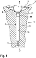
- FIG. 1 shows a partial section through an electrically operated injection valve, which is intended for use in a fuel injection system of an internal combustion engine.
- This fuel injection system is equipped with a high-pressure fuel storage, which is supplied by a high-pressure pump continuously with fuel and from which this fuel via individual electrically controlled Injectors can be supplied to the individual combustion chambers of the internal combustion engine.
- a high-pressure accumulator prevails in the high-pressure accumulator, a pressure in the range of about 2000 bar and, accordingly, the metering device must be able to control such a pressure in the injection valve safely.
- a closing element 4 which in the exemplary embodiment is a valve ball, is pressed by means of an actuator 5 into a conical valve seat 6 or lifted off it.
- the fluid medium which is thus fuel in the exemplary embodiment, is supplied to the injection valve via a bore 2.
- the bore 2 communicates with a relief space 3 via an inlet 7 in connection.
- the inlet 7 in the valve body 8 is part of the ball seat valve. 1
- the inlet 7 has first on the bore 2 side facing a cylindrical Vordrossel 9, to which the valve seat 6 through a cylindrical diffuser 10 connects. At the transition between the Vordrossel 9 and the diffuser 10, a slight bevel may be provided. Due to the cross section of the Vordrossel 9, the flow above the Hubdrosselgrenze is significantly influenced and adjusted by the ball seat valve 1.
- the actuator 5 can be, for example, a magnetic actuator, in which the position of the closing element 4 is set in a targeted manner via an electromagnet.
- the inlet 7 in the direction of the valve seat 6 has a truncated cone section 11, which in turn merges into a diffuser valve seat section 12.
- the diffuser valve seat section 12 adjoins directly to the valve seat 6 or merges into it.
- This area of the ball seat valve 1 is in the detail view according to FIG. 2 shown.
- the truncated cone portion 11 runs without offset in the diffuser 10 and closes with this an angle, in particular in the range of 15 °.
- the truncated cone section 11 On the side facing the valve seat 6 or the diffuser valve seat section 12, the truncated cone section 11 has a sharp-edged shoulder 13, which is connected to the diffuser valve seat section 12 via a cylindrical disk-shaped shoulder wall 14.
- the heel wall 14 is at least approximately perpendicular to the Difforsl ashamedsachse aligned and has a width which is about 25% of the radius of the diffuser 10.
- the diameter of the diffuser valve seat portion 12 at least approximately corresponds to the diameter of the diffuser.
- the embodiment according to the invention is based on the following principles.
- steam is intentionally generated in the pre-throttle 9.
- the steam then condenses already in the diffuser (pressure increase in the stagnation point of the valve ball).
- the cavitation erosion risk in the region of the valve seat 6 of the ball seat valve 1 results.
- the flow bypasses the main danger zone of cavitation erosion in the region of the inlet 7 adjacent to the valve seat 6, as the flow leaves the shoulder 13 and moves in the region of the diffuser valve seat section 12 forms a Totwasser with thus low pressure through the sales wall 14. It comes at the points concerned again for steaming and not for condensation. Avoid condensation areas and thus cavitation erosion in the region of the valve seat 6.
- the mass flow through the Vordrossel 9 remains constant.
Landscapes
- Engineering & Computer Science (AREA)
- General Engineering & Computer Science (AREA)
- Mechanical Engineering (AREA)
- Chemical & Material Sciences (AREA)
- Combustion & Propulsion (AREA)
- Lift Valve (AREA)
- Fuel-Injection Apparatus (AREA)
- Details Of Valves (AREA)
- Taps Or Cocks (AREA)
Claims (5)
- Soupape à siège sphérique pour le réglage d'un débit d'un milieu fluide, présentant un siège de soupape (6) et un élément de fermeture arrondi (4), en particulier une bille de soupape, présentant en outre une entrée (7) avec un pré-étranglement (9) et un diffuseur (10) disposé entre le pré-étranglement (9) et le siège de soupape (6), l'entrée (7) présentant en outre un rétrécissement,
caractérisée en ce que le rétrécissement présente une portion tronconique (11) avec un épaulement à arêtes vives (13) du côté tourné vers le siège de soupape (6), au niveau duquel côté la portion tronconique (11) se prolonge par une portion de siège de soupape de diffuseur cylindrique (12), la portion tronconique (11) formant avec le diffuseur (10) un angle compris entre 5° et 25°, l'épaulement (13) étant connecté à la portion de siège de soupape de diffuseur (12) par le biais d'une paroi d'épaulement (14) en forme de rondelle cylindrique et la paroi d'épaulement (14) étant disposée ou orientée à angle droit par rapport à l'axe longitudinal du diffuseur. - Soupape à siège sphérique selon la revendication 1,
caractérisée en ce que la paroi d'épaulement (14) présente une largeur qui est comprise entre 10 % et 40 % du rayon du diffuseur (10). - Soupape à siège sphérique selon l'une quelconque des revendications précédentes,
caractérisée en ce que la portion de siège de soupape de diffuseur (12) présente un diamètre correspondant au moins approximativement au diamètre de base du diffuseur. - Dispositif d'injection pour l'injection de carburant à partir d'un réservoir haute pression dans une chambre de combustion d'un moteur à combustion interne, comprenant au moins un organe de soupape d'injection pour ouvrir et fermer au moins une ouverture d'injection, comprenant en outre au moins un espace de commande connecté hydrauliquement à l'organe de soupape d'injection,
caractérisé en ce que l'espace de commande est connecté à un espace de décharge par le biais d'au moins une soupape à siège sphérique selon l'une quelconque des revendications précédentes. - Dispositif d'injection selon la revendication 4, caractérisé par
au moins un actionneur électromécanique pour actionner l'élément de fermeture, l'actionneur électromécanique comprenant en particulier un actionneur électromagnétique et/ou un actionneur piézo-électrique.
Applications Claiming Priority (1)
| Application Number | Priority Date | Filing Date | Title |
|---|---|---|---|
| DE102009028943A DE102009028943A1 (de) | 2009-08-27 | 2009-08-27 | Kavitationserosionsoptimiertes Kugelsitzventil |
Publications (3)
| Publication Number | Publication Date |
|---|---|
| EP2290272A2 EP2290272A2 (fr) | 2011-03-02 |
| EP2290272A3 EP2290272A3 (fr) | 2013-08-21 |
| EP2290272B1 true EP2290272B1 (fr) | 2018-05-30 |
Family
ID=42830770
Family Applications (1)
| Application Number | Title | Priority Date | Filing Date |
|---|---|---|---|
| EP10168283.9A Active EP2290272B1 (fr) | 2009-08-27 | 2010-07-02 | Siège de soupape sphérique à érosion par cavitation optimisée |
Country Status (2)
| Country | Link |
|---|---|
| EP (1) | EP2290272B1 (fr) |
| DE (1) | DE102009028943A1 (fr) |
Cited By (1)
| Publication number | Priority date | Publication date | Assignee | Title |
|---|---|---|---|---|
| US11339688B2 (en) | 2020-01-29 | 2022-05-24 | Borgwarner, Inc. | Variable camshaft timing valve assembly |
Families Citing this family (4)
| Publication number | Priority date | Publication date | Assignee | Title |
|---|---|---|---|---|
| DE102012213761A1 (de) * | 2012-08-03 | 2014-02-06 | Robert Bosch Gmbh | Ventilkörper für ein Stellventil und korrespondierendes Magnetventil |
| WO2015097004A1 (fr) * | 2013-12-23 | 2015-07-02 | Robert Bosch Gmbh | Clapet d'injection |
| CN111472910A (zh) * | 2020-03-20 | 2020-07-31 | 常熟理工学院 | 喷射器的控制阀 |
| CN111472913A (zh) * | 2020-03-20 | 2020-07-31 | 常熟理工学院 | 喷油器阀结构 |
Family Cites Families (4)
| Publication number | Priority date | Publication date | Assignee | Title |
|---|---|---|---|---|
| DE19859537A1 (de) * | 1998-12-22 | 2000-07-06 | Bosch Gmbh Robert | Kraftstoffeinspritzventil |
| DE10046416C2 (de) * | 2000-09-18 | 2002-11-07 | Orange Gmbh | Ventilausbildung für Steuerventile |
| DE102006034111A1 (de) * | 2006-07-24 | 2008-01-31 | Robert Bosch Gmbh | Servoventilgesteuerter Injektor zur Einspritzung von Kraftstoff in Zylinderbrennräume von Brennkraftmaschinen; insbesondere Common-Rail-Injektor |
| DE102007004553A1 (de) | 2007-01-30 | 2008-07-31 | Robert Bosch Gmbh | Kugelsitzventil mit verringertem Erosionsverhalten |
-
2009
- 2009-08-27 DE DE102009028943A patent/DE102009028943A1/de not_active Withdrawn
-
2010
- 2010-07-02 EP EP10168283.9A patent/EP2290272B1/fr active Active
Non-Patent Citations (1)
| Title |
|---|
| None * |
Cited By (1)
| Publication number | Priority date | Publication date | Assignee | Title |
|---|---|---|---|---|
| US11339688B2 (en) | 2020-01-29 | 2022-05-24 | Borgwarner, Inc. | Variable camshaft timing valve assembly |
Also Published As
| Publication number | Publication date |
|---|---|
| DE102009028943A1 (de) | 2011-03-03 |
| EP2290272A2 (fr) | 2011-03-02 |
| EP2290272A3 (fr) | 2013-08-21 |
Similar Documents
| Publication | Publication Date | Title |
|---|---|---|
| EP2118480B1 (fr) | Siège de soupape sphérique à comportement d'érosion réduit | |
| EP2290272A2 (fr) | Siège de soupape sphérique à érosion par cavitation optimisée | |
| EP2694796B1 (fr) | Soupape de vidange pour systèmes d'injection d'huile lourde à rampe commune | |
| EP2852754B1 (fr) | Injecteur d'un système d'injection de carburant | |
| DE102009000181A1 (de) | Kraftstoff-Injektor | |
| EP2339164A1 (fr) | Injecteur de carburant à compensation de pression doté d'une dérivation et d'un volume d'espace de soupape minimisé | |
| DE102007029969A1 (de) | Schnellschaltender Kraftstoffinjektor für hohe Einspritzdrücke | |
| EP1319127A1 (fr) | Configuration de soupapes de distribution | |
| EP2807367B1 (fr) | Dispositif d'injection de carburant dans la chambre de combustion d'un moteur a combustion interne | |
| EP2798192B1 (fr) | Injecteur de carburant pour moteur à combustion | |
| EP2511514A2 (fr) | Soupape d'injection de combustible | |
| EP1483499A1 (fr) | Systeme pour moduler en pression le comportement d'injection | |
| DE102009046373A1 (de) | Magnetventil sowie Kraftstoff-Injektor mit einem Magnetventil | |
| EP2957760B1 (fr) | Ensemble de buses pour un injecteur de carburant et injecteur de carburant | |
| EP2459866B1 (fr) | Soupape d'injection de carburant pour moteurs à combustion interne | |
| WO2019170770A1 (fr) | Ensemble comportant une pompe haute pression et un dispositif de régulation disposé en amont de celle-ci | |
| DE102009045556A1 (de) | Injektor | |
| DE102009027187A1 (de) | Kraftstoffinjektor | |
| DE102014117218B4 (de) | Sicherheitsventilsystem | |
| WO2003054384A1 (fr) | Dispositif d'injection de carburant, systeme d'alimentation en carburant et moteur a combustion interne | |
| DE10152253B4 (de) | Ventil zum Steuern von Flüssigkeiten | |
| EP2955366B1 (fr) | Ensemble de buses pour un injecteur de carburant et injecteur de carburant | |
| WO2011026689A1 (fr) | Dispositif d'injection de carburant | |
| DE102012213535A1 (de) | Kraftstoffinjektor | |
| WO2013016745A1 (fr) | Orifices d'étranglement optimisés en termes de cavitation |
Legal Events
| Date | Code | Title | Description |
|---|---|---|---|
| PUAI | Public reference made under article 153(3) epc to a published international application that has entered the european phase |
Free format text: ORIGINAL CODE: 0009012 |
|
| AK | Designated contracting states |
Kind code of ref document: A2 Designated state(s): AL AT BE BG CH CY CZ DE DK EE ES FI FR GB GR HR HU IE IS IT LI LT LU LV MC MK MT NL NO PL PT RO SE SI SK SM TR |
|
| AX | Request for extension of the european patent |
Extension state: BA ME RS |
|
| PUAL | Search report despatched |
Free format text: ORIGINAL CODE: 0009013 |
|
| AK | Designated contracting states |
Kind code of ref document: A3 Designated state(s): AL AT BE BG CH CY CZ DE DK EE ES FI FR GB GR HR HU IE IS IT LI LT LU LV MC MK MT NL NO PL PT RO SE SI SK SM TR |
|
| AX | Request for extension of the european patent |
Extension state: BA ME RS |
|
| RIC1 | Information provided on ipc code assigned before grant |
Ipc: F16K 25/00 20060101ALI20130715BHEP Ipc: F16K 1/42 20060101AFI20130715BHEP |
|
| 17P | Request for examination filed |
Effective date: 20140221 |
|
| RBV | Designated contracting states (corrected) |
Designated state(s): AL AT BE BG CH CY CZ DE DK EE ES FI FR GB GR HR HU IE IS IT LI LT LU LV MC MK MT NL NO PL PT RO SE SI SK SM TR |
|
| 17Q | First examination report despatched |
Effective date: 20161209 |
|
| GRAP | Despatch of communication of intention to grant a patent |
Free format text: ORIGINAL CODE: EPIDOSNIGR1 |
|
| RIC1 | Information provided on ipc code assigned before grant |
Ipc: F16K 25/00 20060101ALI20180112BHEP Ipc: F16K 1/42 20060101AFI20180112BHEP Ipc: F02M 61/18 20060101ALI20180112BHEP |
|
| INTG | Intention to grant announced |
Effective date: 20180202 |
|
| GRAS | Grant fee paid |
Free format text: ORIGINAL CODE: EPIDOSNIGR3 |
|
| GRAA | (expected) grant |
Free format text: ORIGINAL CODE: 0009210 |
|
| AK | Designated contracting states |
Kind code of ref document: B1 Designated state(s): AL AT BE BG CH CY CZ DE DK EE ES FI FR GB GR HR HU IE IS IT LI LT LU LV MC MK MT NL NO PL PT RO SE SI SK SM TR |
|
| REG | Reference to a national code |
Ref country code: GB Ref legal event code: FG4D Free format text: NOT ENGLISH |
|
| REG | Reference to a national code |
Ref country code: CH Ref legal event code: EP |
|
| REG | Reference to a national code |
Ref country code: AT Ref legal event code: REF Ref document number: 1003935 Country of ref document: AT Kind code of ref document: T Effective date: 20180615 |
|
| REG | Reference to a national code |
Ref country code: IE Ref legal event code: FG4D Free format text: LANGUAGE OF EP DOCUMENT: GERMAN |
|
| REG | Reference to a national code |
Ref country code: DE Ref legal event code: R096 Ref document number: 502010015015 Country of ref document: DE |
|
| REG | Reference to a national code |
Ref country code: FR Ref legal event code: PLFP Year of fee payment: 9 |
|
| REG | Reference to a national code |
Ref country code: NL Ref legal event code: MP Effective date: 20180530 |
|
| REG | Reference to a national code |
Ref country code: LT Ref legal event code: MG4D |
|
| PG25 | Lapsed in a contracting state [announced via postgrant information from national office to epo] |
Ref country code: LT Free format text: LAPSE BECAUSE OF FAILURE TO SUBMIT A TRANSLATION OF THE DESCRIPTION OR TO PAY THE FEE WITHIN THE PRESCRIBED TIME-LIMIT Effective date: 20180530 Ref country code: FI Free format text: LAPSE BECAUSE OF FAILURE TO SUBMIT A TRANSLATION OF THE DESCRIPTION OR TO PAY THE FEE WITHIN THE PRESCRIBED TIME-LIMIT Effective date: 20180530 Ref country code: CY Free format text: LAPSE BECAUSE OF FAILURE TO SUBMIT A TRANSLATION OF THE DESCRIPTION OR TO PAY THE FEE WITHIN THE PRESCRIBED TIME-LIMIT Effective date: 20180530 Ref country code: NO Free format text: LAPSE BECAUSE OF FAILURE TO SUBMIT A TRANSLATION OF THE DESCRIPTION OR TO PAY THE FEE WITHIN THE PRESCRIBED TIME-LIMIT Effective date: 20180830 Ref country code: BG Free format text: LAPSE BECAUSE OF FAILURE TO SUBMIT A TRANSLATION OF THE DESCRIPTION OR TO PAY THE FEE WITHIN THE PRESCRIBED TIME-LIMIT Effective date: 20180830 Ref country code: SE Free format text: LAPSE BECAUSE OF FAILURE TO SUBMIT A TRANSLATION OF THE DESCRIPTION OR TO PAY THE FEE WITHIN THE PRESCRIBED TIME-LIMIT Effective date: 20180530 Ref country code: ES Free format text: LAPSE BECAUSE OF FAILURE TO SUBMIT A TRANSLATION OF THE DESCRIPTION OR TO PAY THE FEE WITHIN THE PRESCRIBED TIME-LIMIT Effective date: 20180530 |
|
| PG25 | Lapsed in a contracting state [announced via postgrant information from national office to epo] |
Ref country code: LV Free format text: LAPSE BECAUSE OF FAILURE TO SUBMIT A TRANSLATION OF THE DESCRIPTION OR TO PAY THE FEE WITHIN THE PRESCRIBED TIME-LIMIT Effective date: 20180530 Ref country code: HR Free format text: LAPSE BECAUSE OF FAILURE TO SUBMIT A TRANSLATION OF THE DESCRIPTION OR TO PAY THE FEE WITHIN THE PRESCRIBED TIME-LIMIT Effective date: 20180530 Ref country code: GR Free format text: LAPSE BECAUSE OF FAILURE TO SUBMIT A TRANSLATION OF THE DESCRIPTION OR TO PAY THE FEE WITHIN THE PRESCRIBED TIME-LIMIT Effective date: 20180831 |
|
| PG25 | Lapsed in a contracting state [announced via postgrant information from national office to epo] |
Ref country code: NL Free format text: LAPSE BECAUSE OF FAILURE TO SUBMIT A TRANSLATION OF THE DESCRIPTION OR TO PAY THE FEE WITHIN THE PRESCRIBED TIME-LIMIT Effective date: 20180530 |
|
| PG25 | Lapsed in a contracting state [announced via postgrant information from national office to epo] |
Ref country code: DK Free format text: LAPSE BECAUSE OF FAILURE TO SUBMIT A TRANSLATION OF THE DESCRIPTION OR TO PAY THE FEE WITHIN THE PRESCRIBED TIME-LIMIT Effective date: 20180530 Ref country code: PL Free format text: LAPSE BECAUSE OF FAILURE TO SUBMIT A TRANSLATION OF THE DESCRIPTION OR TO PAY THE FEE WITHIN THE PRESCRIBED TIME-LIMIT Effective date: 20180530 Ref country code: EE Free format text: LAPSE BECAUSE OF FAILURE TO SUBMIT A TRANSLATION OF THE DESCRIPTION OR TO PAY THE FEE WITHIN THE PRESCRIBED TIME-LIMIT Effective date: 20180530 Ref country code: RO Free format text: LAPSE BECAUSE OF FAILURE TO SUBMIT A TRANSLATION OF THE DESCRIPTION OR TO PAY THE FEE WITHIN THE PRESCRIBED TIME-LIMIT Effective date: 20180530 Ref country code: CZ Free format text: LAPSE BECAUSE OF FAILURE TO SUBMIT A TRANSLATION OF THE DESCRIPTION OR TO PAY THE FEE WITHIN THE PRESCRIBED TIME-LIMIT Effective date: 20180530 Ref country code: SK Free format text: LAPSE BECAUSE OF FAILURE TO SUBMIT A TRANSLATION OF THE DESCRIPTION OR TO PAY THE FEE WITHIN THE PRESCRIBED TIME-LIMIT Effective date: 20180530 |
|
| PG25 | Lapsed in a contracting state [announced via postgrant information from national office to epo] |
Ref country code: SM Free format text: LAPSE BECAUSE OF FAILURE TO SUBMIT A TRANSLATION OF THE DESCRIPTION OR TO PAY THE FEE WITHIN THE PRESCRIBED TIME-LIMIT Effective date: 20180530 Ref country code: IT Free format text: LAPSE BECAUSE OF FAILURE TO SUBMIT A TRANSLATION OF THE DESCRIPTION OR TO PAY THE FEE WITHIN THE PRESCRIBED TIME-LIMIT Effective date: 20180530 |
|
| REG | Reference to a national code |
Ref country code: CH Ref legal event code: PL |
|
| REG | Reference to a national code |
Ref country code: DE Ref legal event code: R097 Ref document number: 502010015015 Country of ref document: DE |
|
| PG25 | Lapsed in a contracting state [announced via postgrant information from national office to epo] |
Ref country code: LU Free format text: LAPSE BECAUSE OF NON-PAYMENT OF DUE FEES Effective date: 20180702 Ref country code: MC Free format text: LAPSE BECAUSE OF FAILURE TO SUBMIT A TRANSLATION OF THE DESCRIPTION OR TO PAY THE FEE WITHIN THE PRESCRIBED TIME-LIMIT Effective date: 20180530 |
|
| REG | Reference to a national code |
Ref country code: BE Ref legal event code: MM Effective date: 20180731 |
|
| PLBE | No opposition filed within time limit |
Free format text: ORIGINAL CODE: 0009261 |
|
| STAA | Information on the status of an ep patent application or granted ep patent |
Free format text: STATUS: NO OPPOSITION FILED WITHIN TIME LIMIT |
|
| REG | Reference to a national code |
Ref country code: IE Ref legal event code: MM4A |
|
| GBPC | Gb: european patent ceased through non-payment of renewal fee |
Effective date: 20180830 |
|
| PG25 | Lapsed in a contracting state [announced via postgrant information from national office to epo] |
Ref country code: IE Free format text: LAPSE BECAUSE OF NON-PAYMENT OF DUE FEES Effective date: 20180702 Ref country code: CH Free format text: LAPSE BECAUSE OF NON-PAYMENT OF DUE FEES Effective date: 20180731 Ref country code: LI Free format text: LAPSE BECAUSE OF NON-PAYMENT OF DUE FEES Effective date: 20180731 |
|
| 26N | No opposition filed |
Effective date: 20190301 |
|
| PG25 | Lapsed in a contracting state [announced via postgrant information from national office to epo] |
Ref country code: SI Free format text: LAPSE BECAUSE OF FAILURE TO SUBMIT A TRANSLATION OF THE DESCRIPTION OR TO PAY THE FEE WITHIN THE PRESCRIBED TIME-LIMIT Effective date: 20180530 Ref country code: BE Free format text: LAPSE BECAUSE OF NON-PAYMENT OF DUE FEES Effective date: 20180731 |
|
| REG | Reference to a national code |
Ref country code: AT Ref legal event code: MM01 Ref document number: 1003935 Country of ref document: AT Kind code of ref document: T Effective date: 20180702 |
|
| PG25 | Lapsed in a contracting state [announced via postgrant information from national office to epo] |
Ref country code: GB Free format text: LAPSE BECAUSE OF NON-PAYMENT OF DUE FEES Effective date: 20180830 |
|
| PG25 | Lapsed in a contracting state [announced via postgrant information from national office to epo] |
Ref country code: AL Free format text: LAPSE BECAUSE OF FAILURE TO SUBMIT A TRANSLATION OF THE DESCRIPTION OR TO PAY THE FEE WITHIN THE PRESCRIBED TIME-LIMIT Effective date: 20180530 |
|
| PG25 | Lapsed in a contracting state [announced via postgrant information from national office to epo] |
Ref country code: AT Free format text: LAPSE BECAUSE OF NON-PAYMENT OF DUE FEES Effective date: 20180702 |
|
| PG25 | Lapsed in a contracting state [announced via postgrant information from national office to epo] |
Ref country code: MT Free format text: LAPSE BECAUSE OF FAILURE TO SUBMIT A TRANSLATION OF THE DESCRIPTION OR TO PAY THE FEE WITHIN THE PRESCRIBED TIME-LIMIT Effective date: 20180530 |
|
| PG25 | Lapsed in a contracting state [announced via postgrant information from national office to epo] |
Ref country code: TR Free format text: LAPSE BECAUSE OF FAILURE TO SUBMIT A TRANSLATION OF THE DESCRIPTION OR TO PAY THE FEE WITHIN THE PRESCRIBED TIME-LIMIT Effective date: 20180530 |
|
| PG25 | Lapsed in a contracting state [announced via postgrant information from national office to epo] |
Ref country code: HU Free format text: LAPSE BECAUSE OF FAILURE TO SUBMIT A TRANSLATION OF THE DESCRIPTION OR TO PAY THE FEE WITHIN THE PRESCRIBED TIME-LIMIT; INVALID AB INITIO Effective date: 20100702 Ref country code: PT Free format text: LAPSE BECAUSE OF FAILURE TO SUBMIT A TRANSLATION OF THE DESCRIPTION OR TO PAY THE FEE WITHIN THE PRESCRIBED TIME-LIMIT Effective date: 20180530 |
|
| PG25 | Lapsed in a contracting state [announced via postgrant information from national office to epo] |
Ref country code: MK Free format text: LAPSE BECAUSE OF NON-PAYMENT OF DUE FEES Effective date: 20180530 |
|
| PG25 | Lapsed in a contracting state [announced via postgrant information from national office to epo] |
Ref country code: IS Free format text: LAPSE BECAUSE OF FAILURE TO SUBMIT A TRANSLATION OF THE DESCRIPTION OR TO PAY THE FEE WITHIN THE PRESCRIBED TIME-LIMIT Effective date: 20180930 |
|
| PGFP | Annual fee paid to national office [announced via postgrant information from national office to epo] |
Ref country code: DE Payment date: 20250924 Year of fee payment: 16 |
|
| PGFP | Annual fee paid to national office [announced via postgrant information from national office to epo] |
Ref country code: FR Payment date: 20250723 Year of fee payment: 16 |