EP2290330B1 - Einzelstrahlflüssigkeitsströmungsmesser mit vergrössertem Drehmoment und verbesserter Empfindlichkeit - Google Patents
Einzelstrahlflüssigkeitsströmungsmesser mit vergrössertem Drehmoment und verbesserter Empfindlichkeit Download PDFInfo
- Publication number
- EP2290330B1 EP2290330B1 EP09382161A EP09382161A EP2290330B1 EP 2290330 B1 EP2290330 B1 EP 2290330B1 EP 09382161 A EP09382161 A EP 09382161A EP 09382161 A EP09382161 A EP 09382161A EP 2290330 B1 EP2290330 B1 EP 2290330B1
- Authority
- EP
- European Patent Office
- Prior art keywords
- ribs
- flowmeter
- turbine
- approximately
- nozzle
- Prior art date
- Legal status (The legal status is an assumption and is not a legal conclusion. Google has not performed a legal analysis and makes no representation as to the accuracy of the status listed.)
- Active
Links
Images




Classifications
-
- G—PHYSICS
- G01—MEASURING; TESTING
- G01F—MEASURING VOLUME, VOLUME FLOW, MASS FLOW OR LIQUID LEVEL; METERING BY VOLUME
- G01F1/00—Measuring the volume flow or mass flow of fluid or fluent solid material wherein the fluid passes through a meter in a continuous flow
- G01F1/05—Measuring the volume flow or mass flow of fluid or fluent solid material wherein the fluid passes through a meter in a continuous flow by using mechanical effects
- G01F1/06—Measuring the volume flow or mass flow of fluid or fluent solid material wherein the fluid passes through a meter in a continuous flow by using mechanical effects using rotating vanes with tangential admission
- G01F1/08—Adjusting, correcting or compensating means therefor
Definitions
- the present invention relates to a single-jet meter for fluids that presents an accurate, precise and stable measurement in a wide range of flow rates within metrological parameters.
- This flowmeter has a meter chamber wherein a set of hydraulic elements allow the obtention of a measurement range that has metrological parameters with enhanced accuracy and precision within a wide range of flows, and specially in low flows.
- the present invention relates to single-jet water flowmeters. These flowmeters as in US 6 079 281 , GB 437 637 and EP 0 718 602 are based on the rotation of the turbine produced by fluid flow upon entering the measuring chamber in the form of a jet that impacts several of the blades or vanes of a turbine.
- the counter totaliser records the consumption on the basis of the revolutions completed by the turbine. Thus, the deviation between the ratio established in the totaliser and that which really occurs with each flow rate results in an error in the measurement of the consumed volume.
- the metrological characteristics of a single-jet flowmeter are thus determined by their hydraulic design, which is formed by the arrangement of hydraulic elements. These metrological characteristics determine the metrological error curve that measures the deviation of the measured volume from the real volume, due to the non-linear ratio between flow rate and turbine rotation speed.
- the metrological error curve of the flowmeter records the error incurred in in all flow rates within its measurement range, in such a manner that it reflects the metrological characteristics of the flowmeter. Typical metrological ranges are typically described in standard EN14154.
- the metrological error curve only the highest range of flow rates shows small variations (in the order of 1,000 l/h). Therefore, the error can be considered constant and the metrological error curve does not usually deviate excessively from a horizontal straight line, due to which it has little difficulty in keeping within the limits established by the standard. It is known that, in high flow rates, the turbulences produced within the measuring chamber of the flowmeter, maximised by the use of ribs, favour a linear ratio between turbine rotation speed ( ⁇ ) and flow rate (Q), and therefore the volume of fluid that passes through the flowmeter which is recorded or measured within the metrological ranges.
- the error is within the range ⁇ 2% within a flow rate interval Q 2 ⁇ Q ⁇ Q 4 and ⁇ 5% within an interval Q 1 ⁇ Q ⁇ Q 2 .
- the linearising effect of the turbulence gradually disappears as flow rate value drops and the metrological error curve can undergo more significant changes. Said changes can occur with a positive or negative slope when the specific flow rate declines, influenced by the hydraulic design of the flowmeter.
- the effects derived from the friction also contribute, jointly with the hydraulic design.
- the effects derived from the friction between the mobile parts of a flowmeter, such as the turbine and measuring chamber thereof play an increasingly relevant role as the flow rate passing through the flowmeter declines.
- the results of the simulations allow for the obtention of single-jet flowmeters effects on the metrological characteristics. These effects contribute in low flow rates to the negative curve error for high increases in friction, said eventuality requiring a hydraulic design that will minimise the effects of the friction and supply sufficient energy to overcome said effects.
- the sensitivity of the flowmeter is limited, where sensitivity is understood as its capacity to carry out precise consumption measurements with smaller flow rates, to the point that it is unable to measure with the accuracy required by the metrological ranges of consumptions below a minimum flow rate.
- This circumstance normally prevents single-jet flowmeters from being able to measure the consumptions originated by the leaks that occur in the facilities of the subscribers. For this reason, the capacity to improve flowmeter sensitivity in order to reduce the error observed in the metrological curve is of great interest.
- the metrological characteristics of single-jet flowmeters are very susceptible to both hydraulic accidents upstream of the flowmeter and small variations that occur in the dimensions and position of the elements that constitute the hydraulic design of the flowmeter.
- the metrological curves of different units with identical flowmeter design may have substancial variations in their metrological characteristics that require enabling a form of regulation to maintain said curve within the limits established by the standard.
- One contribution is the variation in hydraulic and friction parameters induced by wear of the parts. This wear increases with turbine rotation speed.
- the calcareous deposits that are normally formed on the different elements during use may also modify their dimensions and produce an effect similar to the previous. Therefore, obtaining a hydraulic design that will provide the flowmeter with sufficient metrological stability against small variations that may arise during the mass manufacturing process or during use is of great interest.
- a single-jet stream fluid flowmeter in an wide flow rate range, 4 l/h to 5,000 l/h, is desirable, wherein the linear ratio between turbine rotation speed and the flow rate, and therefore the number of revolutions completed by the turbine, is proportional to the volume of water that passes through the flowmeter witin the metrological parameters. Said proportional ratio must be stable against small variations in the dimensions of the hydraulic elements, such as external accidents or calcareous deposits or tolerances during manufacture.
- the object of the invention is to provide a flow meter wherein the arrangement and friction of the hydraulic elements provide great sensitivity in measuring the volume of fluid recorded within an extensive range of flow rates (from 4 l/h to 5,000 l/h), included in particular flow rates smaller than 10 l/h.
- This sensitivity will allow the flowmeter to determine volume measurement with precision and accuracy within the metrological parameters reflected in a metrological error curve, and to be metrologically stable against both hydraulic accidents upstream of the flowmeter and slight variations in the dimensions and position of the elements that constitute the hydraulic design of the flowmeter.
- Said flowmeter is defined by independent claim 1.
- a process for measuring fluid volume using a flowmeter according to independent claim 10 is provided.
- the single-jet stream-type fluid flowmeter is arranged next to a duct where the liquid enters into an original flow direction (X).
- the flowmeter is comprised of a measuring chamber, a pair of nozzles and a turbine the rotational axis whereof is perpendicular to the original direction of the liquid flow entrance.
- the measuring chamber forms an internal enclosure delimited by a first upper wall and a second lower wall, substantially parallel to each other, wherebetween a side wall extends, in such a manner that the enclosure of the camera is substantially cylindrical. Orifices for nozzles are arranged on said side wall.
- the inner face of the first and second upper and lower wall is substantially perpendicular to the rotational axis of the turbine and has an adapted zone for housing the turbine axis. In this flowmeter, the turbine has 11 blades or vanes.
- a set of ribs is arranged on both the first and second wall which project towards the interior of the chamber. These ribs are arranged radially with respect to the rotational axis of the turbine. There are four upper ribs arranged at regular intervals, substantially at an angle of 90° ⁇ 10° therebetween, in the form of a cross. The upper ribs extend partially through the chamber (between 50% and 90% of its radius) between the point of support of the turbine and the side wall of the chamber. The width of these members varies between 10% and 15% of radius value.
- lower ribs arranged radially with respect to the rotational axis of the turbine, at regular intervals, substantially at an angle of 60° ⁇ 10° therebetween, in the shape of a star.
- the lower ribs extend substantially throughout the radius towards the supporting element (between 60% and 100% of its radius) between the turbine point of support and the chamber side wall.
- the width of these lower ribs is similar to that of the upper ribs (from 10% to 15% of radius value).
- the nerves project substantially from the inner face of each wall, between 20% and 30% of the height of the measuring chamber.Preferably 25%, the ratio between the height of each of the upper ribs that project outwards being approximately between 1.5 and 1.7 times higher than the height of each of the lower ribs.
- This difference in rib height allows the turbulence associated to the upper members to be substantially greater.
- This effect provides the turbine with an additional normal component. Said normal component guarantees the support of the turbine and controls the degree of friction through the bearing. The dependence of the friction force of the normal component on the force during mechanical contact is conditioned by the impulsion of the fluid in said direction due to the effects derived from the turbulences generated by the upper and lower ribs.
- Two of the opposing upper nerves are arranged as substantially parallel ( ⁇ 5°) to the first original direction of entrance.
- two of the lower opposing ribs are substantially opposed to these two lower upper ribs, and therefore in a direction substantially parallel to the original direction of entrance.
- these four ribs define an impelling zone in the space comprised between the two ribs and the side wall wherein the nozzle orifices are arranged. In this impelling zone the fluid penetrates the chamber, impels the turbine vanes or blades and exits the measuring chamber.
- the fluid enters this zone through a first nozzle, the axis whereof is substantially deviated from the original direction of liquid flow entrance at an angle between 11° and 20°.
- the first nozzle extends along its axis of revolution and initially comprises a truncated cone-shaped cross-section followed by a circular cross-section that has a nozzle radius comprised between 8% and 14% of the radius value of the measuring chamber.
- the distance between the intersection of the axis of the first nozzle and the axis of X up to the centre of the chamber is between 90% and 100% of the radius of the measuring chamber.
- the axis of the second nozzle froms a second angle with the original direction of entrance between 5° and 15°.
- the second nozzle extends along its axis of revolution with a circular cross-section that has a nozzle radius comprised between 10% and 14% of the value of the radius of the measuring chamber.
- the distance between the intersection of the axis of the second nozzle and the axis of X up to the centre of the chamber is between 60% and 75% of the radius of the measuring chamber.
- the turbine, arrangement and dimensions of the hydraulic elements that comprise the upper and lower ribs of the chamber, the first and second nozzles and turbine vanes, determine the metrological characteristics of the flowmeter on determining turbine dynamics.
- the impulsion of the fluid is counteracted by the friction and therefore, these elements leverage the flow energy of the fluid circulating through the flowmeter, also with low flow rates, and impel the turbine in such a manner as to overcome the linear friction caused by the mechanical elements throughout the metrological range, especially in the case of low flow rates where friction phenomena are greater.
- said elements are susceptible to dimensional changes due to variations in the manufacturing processes or to geometric variations due to use in the facility; said changes occasionally produce variations in the metrological efficiency of the flowmeter, causing measurement irregularities. Thanks to the sensitivity provided by the different main elements, and to the high flow profile disturbance level, produced by the difference in height between the upper and lower ribs, the disturbances created within the measuring chamber annul the variations in the flow formed upstream and downstream of the device, resulting in the high stability of the flow profile on entering the counter, exceeding in any case the requirements expressed by the different standards relative to these devices (EN141154), avoiding the need to use flow stabilisers in all cases, both upstream and downstream.
- a measurement process for measuring with the accuracy and stability required by the metrological parameters comprised in the arrangement of a flowmeter that comprises the following stages:
- Figure 1 shows a general view of a cross-section of flowmeter (70).
- Said flowmeter has a turbine (60) in a measuring chamber (63).
- the fluid penetrates chamber (63) through a first nozzle (64) and exits it through a second nozzle (65).
- a counting mechanism (71) joined to turbine (60) by means of a transmission element can be observed.
- said transmission is carried out using a group of magnets that are entirely comprised within the meter chamber (63).
- Measuring chamber (63) has a substantially cylindrical shape.
- the radius of this chamber ranges from 26 mm to 28 mm; more preferably, 27.5 mm.
- the height of this chamber ranges from 20 mm to 23 mm; more preferably, 21.35 mm.
- the eleven-blade turbine (60) preferably has an outer diameter ranging from 51 mm to 53 mm and, more preferably, 52 mm.
- the inner diameter of the turbine (60) varies between 15 mm to 17 mm and, more preferably, is 16 mm.
- the height of the turbine (60) varies between 8 mm and 10 mm and, more preferably, is 9 mm.
- the turbine (60) vanes are arranged at intervals, as the angle between the turbine (60) blades varies between 31 ° and 34° and, more preferably, is 32.7°.
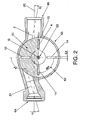
- Figure 2 shows a bottom plan view of the measuring chamber (63) and the first and second nozzles (64, 65) of the flowmeter (70).
- the radius of the circular cross-section of the first nozzle ranges from 4.5 mm to 6 mm and, more preferably, is 5.25 mm.
- the truncated cone ratio is preferably 1:10 at the entrance to the first nozzle (64).
- the axis (1) of the first nozzle (64) forms an angle (C) with the original direction of fluid entrance (X).
- this angle (C) varies between 10° and 20° and, more preferably, is 17°.
- the distance between the intersection of the axis of the first nozzle (64) with the axis of X up to the centre of the chamber is approximately 52 mm.
- the axis (2) of the second nozzle (65) forms an angle (D) with the original direction of fluid entrance (X).
- the angle of (D) ranges from 5° to 15° and, more preferably, is 11°.
- the second nozzle preferably has a circular cross-section of radius ranging from 6 mm to 7.5 mm, with 6.75 mm being the preferred value.
- the distance between the intersection of the axis of the second nozzle with the axis of X and the centre of the chamber is preferably approximately 39 mm.
- a first upper wall (62) in chamber (63) comprises four upper ribs (11, 12, 13, 14) arranged in the form of a cross.
- the angle between these ribs is 90° ⁇ 5°. More preferably it is 90°.
- Two of these upper ribs (11, 13) are opposed and arranged parallel to axis (X), in such a manner that they form an angle (A4) between the axis (1) of the first nozzle (64) and rib (12) is comprised in the range of 98° to 128° and, preferably, is 108°.
- an impulsion zone (30) between the upper (11) and lower (13) ribs can be observed.
- the ratio between the height of the upper ribs (11-14) and the lower ribs (41-46) is 1:64.
- the dimensions of the upper ribs (11, 12, 13, 14) have a length of 13 mm to 18 mm; more preferably, 13 mm. Preferably, the width ranges from 2 mm to 3 mm; more preferably, 2.5 mm. These members project to a height of between 5 mm and 6 mm; more preferably, 5.75 mm.
- a wall (53) zone can be observed around rotational axis (G), adapted so as to come into contact with turbine (60).
- Figure 3 shows a plan view of the measuring chamber (63) and of the first and second nozzles (64, 65) of the flowmeter (70).
- a second lower wall (62) in chamber (63) comprises six lower ribs (41, 42, 43, 44, 45, 46) arranged in the form of a star.
- the angle between these nerves is 60° ⁇ 5°; more preferably, 60°.
- Two opposing members (41, 44) are arranged parallel to the original direction of fluid entrance (X) and opposed to the upper ribs (1l, 13).
- the upper rib (42) and the lower rib (52) form an angle of 30° ⁇ 5°; more preferably, 30°.
- the angle (A5) between the rib (42) is 98° ⁇ 10°. More preferably, this angle is 98°+1°.
- These lower ribs (41-46) preferably have a length ranging from 16 mm to 20 mm; more preferably, 17 mm.
- the width of these lower ribs ranges from 2 mm to 3 mm; more preferably, 2.5 mm.
- these members project at a height of 3 mm to 4 mm; more preferably, 3.5 mm.
- a wall (51) zone can be observed around the rotational axis (G) adapted so as to come into contact with the turbine (60).
- This zone has a rotation bearing adapted so as to come into contact with the lower end (52) of turbine (60), which ends in a spherical cap.
- turbine (60) is arranged in measuring chamber (63) with its rotational axis on an adapted wall (51) zone, which is a rotation bearing and is perpendicular to the direction of flow.
- the ratio is 3.5:1 between the radii of the sphere of the rotation bearing of the turbine and the sphere of the upper end (52) of the axis around which said bearing rotates.
- figure 5 is represented the perpetrated relative error in % with respect to the logarithm of the flow rate circulating through the flowmeter and the metrological curve described in standard EN14154.
- Figure 5A shows the metrological error curve corresponding to a flowmeter according to Table 1. The dependence of the error committed with the flow rate displays a non-linear behaviour that positions it above the tolerated metrological levels.
- Table 1 turbine (60) number of vanes; 5 angle between vanes (°) 360/5 measuring chamber (61) chamber radius (mm) 27.5 chamber height (mm) 21.35 lower chamber/turbine contact zone: Ratio: 2:1 Radius of lower spherical turbine cap (52) vs Radius of the spherical chamber zone rotation bearing (51) Upper ribs # of upper ribs (4); 4 ribs (11-13) parallel to the X direction 2 height (mm) 5.75 Width (mm) 2.5 length (mm) 13 Angle A4 (°) : 90 Lower ribs # lower ribs 4 ribs (41-44) parallel to the X direction 2 height (mm) 3.5 width (mm) 2.5 length (mm) 17 Angle A5 (°) : 80 First nozzle (64) Angle C (°) 15 nozzle (64) axis (2) length (mm) 6 circular nozzle (64) radius (mm) 9.5 Second nozzle (65) Angle D (°) nozzle axis (65) length (mm) 7.5 circular nozzle (65) radius (mm)
- figure 6 is shown the variation in the metrological characteristics of a flowmeter that has the characteristics of Table 2, on changing the height ratio between the upper (11-14) and lower (41-46) ribs: (A) 4.75:3.5, (B) 5.75:3.5, (C) 6.50:3.50.
- figure 7 is shown the variation in the metrological characteristics of a flowmeter that has the characteristics of Table 2, on changing the number of lower ribs between four ribs (A), six ribs (B) and eight ribs (C).
- FIG 8 is shown how turbine rotation speed varies according to the rotation angle thereof for a flowmeter that has four ribs (curve T1), six ribs (curve T2) and eight ribs (curve T3).
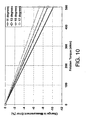
- flowmeter stability limits the dependence of metrological error with the friction torque. For a flow rate of 15 l/h, this error is less than 10% in the range of 0 to 500 nNm of the friction torque. This dependence causes error slope variation with the torque to vary between 1.4 and 2.0 for an interval of 11° to 17° as the angle (C) of the nozzle axis (64) with the original direction (X) of a flowmeter that has the technical characteristics of Table 2. In figure 10 is shown, for a flow rate of 15 l/h, the variation in the metrological error with the friction torque for an angle (C) of 11°, 13°, 15° and 17°.
- figure 11 is shown the metrological error curve for a flowmeter that has the characteristics of Table 2 with an error within the range of ⁇ 5% for flow rates greater than 4 l/h.
Landscapes
- Physics & Mathematics (AREA)
- Fluid Mechanics (AREA)
- General Physics & Mathematics (AREA)
- Measuring Volume Flow (AREA)
Claims (10)
- Einzelstrahlflussmessgerät (70), das aufweist:eine Turbine (60) mit elf Schaufeln, die in gleichmäßigen Abständen beabstandet sind, welche eine Drehachse (G) senkrecht zu einer ursprünglichen Richtung eines Fluidflusseintritts (X) hat,eine erste Düse (64),eine zweite Düse (65), undeine Messgerätmesskammer (63), die umfasst:eine erste obere Wand (62), die vier obere Rippen (11 - 14) und einen Wandbereich (53) um die Drehachse (G) umfasst,der ausgelegt ist, um in Kontakt mit der Turbine (60) zu gelangen,eine zweite untere Wand (61), die sechs untere Rippen (41 - 46) umfasst und einen Wandbereich (51) um die Drehachse (G), der ausgelegt ist, um in Kontakt mit der Turbine (60) zu gelangen, undeine Seitenwand der Messkammer (63), die Öffnungen zum Koppeln mit der ersten Düse (64) und der zweiten Düse (65) umfasst,wobeidie vier oberen Rippen (11 - 14) radial bezüglich der Drehachse (G) der Turbine (60) angeordnet sind, bei gleichmäßigen Abständen von 90° ± 10° dazwischen, wobei die oberen Rippen (11 - 14) sich radial zwischen 50 % und 90 % des Radius der Messkammer (63) erstrecken, wobei die Breite dieser Rippen zwischen 10 % und 15 % des Werts des Radius der Messkammer (63) liegt, wobei die Höhe der oberen Rippen (11 - 14) zwischen 1,5 und 1,7 mal der Höhe der unteren Rippen (41 - 46) ist,die sechs unteren Rippen (41 - 46) radial bezüglich der Drehachse (G) der Turbine (60) angeordnet sind, bei gleichmäßigen Abständen von 60° ± 10° dazwischen, wobei die unteren Rippen (41 - 46) sich radial zwischen 60 % und 100 % des Radius der Messkammer (63) erstrecken, wobei die Breite dieser Rippen zwischen 10 % und 15 % des Werts des Radius der Messkammer (63) ist, wobei die Höhe der unteren Rippen (41 - 46) zwischen 20 % und 30 % der Höhe der Messkammer (63) umfasst ist, unddie oberen Rippen (11 - 14) bezüglich der unteren Rippen (41 - 46) auf eine solche Weise angeordnet sind, dass:die Mitte der vier Rippen (11 bis 14) und der sechs unteren Rippen (41 bis 46) zu der Drehachse (G) der Turbine (60) ausgerichtet ist, wobeizwei gegenüberliegende obere Rippen (11, 13) und zwei gegenüberliegende untere Rippen (41, 44) in einer Richtung näherungsweise parallel zu der ursprünglichen Richtung des Fluidflusseintritts (X) sind,die Achse (1) der ersten Düse (64) einen Winkel (C) mit der Achse (1) der Einlassdüse (64) bezüglich der ursprünglichen Richtung des Fluidflusseintritts (X) bilden, umfasst zwischen 10° und 20°.
- Flussmessgerät nach Anspruch 1, bei dem der Radius der Messkammer (63) des Flussmessgeräts näherungsweise 27,5 mm und die Höhe näherungsweise 21,35 mm beträgt.
- Flussmessgerät nach einem der vorstehenden Ansprüche, bei dem die Höhe der Rippen näherungsweise 1,64 mal der Höhe der unteren Rippen ist.
- Flussmessgerät nach einem der vorstehenden Ansprüche, bei dem die Höhe der oberen Rippen näherungsweise 5,75 mm beträgt.
- Flussmessgerät nach einem der vorstehenden Ansprüche, bei dem der Winkel (A4) zwischen der ersten Düse (64) und der zweiten oberen Rippe (12) näherungsweise 108° beträgt.
- Flussmessgerät nach einem der vorstehenden Ansprüche, bei dem das Verhältnis zwischen dem Kreis der Turbinendrehlagerung und dem Kreis des oberen Endes (52) der Achse, um die Lagerung dreht, 3,5 : 1 ist.
- Flussmessgerät nach einem der vorstehenden Ansprüche, bei dem die oberen Rippen (11 - 14) sich zwischen 50 % und 80 % des Werts des Radius der Messkammer um den Mittelpunkt zwischen der Seitenwand und der Drehachse (G) der Turbine (60) erstrecken.
- Flussmessgerät nach einem der vorstehenden Ansprüche, bei dem der Winkel (C) der Achse (1) der ersten Düse (64) und der Richtung (X) zwischen 15° und 18° variiert.
- Flussmessgerät nach Anspruch 1, bei dem:der Radius der Messkammer (63) näherungsweise 27,5 mm unddie Höhe der Messkammer (63) näherungsweise 21, 35 mm beträgt,die oberen Rippen (11 - 14) radial angeordnet sind, wobei deren Schnittpunkt mit der Drehachse (G) der Turbine (60) bei regelmäßigen Winkelabständen von näherungsweise 90° übereinstimmt,jede der oberen Rippen (11 - 14) eine Länge von näherungsweise 13 mm, eine Breite (E4) von näherungsweise 2,5 mm und eine Höhe in dem Bereich von 5,7 mm und 5,8 mm hat,die unteren Rippen (41 - 46) radial angeordnet sind, wobei deren Schnittpunkt mit der Drehachse (G) der Turbine (60) bei regelmäßigen Winkelabständen von näherungsweise 60° übereinstimmt,jede der unteren Rippen (41 - 46) eine Länge von näherungsweise 17 mm, eine Breite (E5) von näherungsweise 2,5 mm und eine Höhe von näherungsweise 3,5 mm hat,wobei das Flussmessgerät angeordnet istmit einer oberen Rippe (42) und einer unteren Rippe (52),die einen Winkel von näherungsweise 30° bilden,einen Winkel (A4) zwischen der Achse der ersten Düse (64) und der zweiten oberen Rippe (12) von näherungsweise 108° bildend,und die Turbine (60) einen Winkel zwischen den elf Schaufeln der Turbine (60) von näherungsweise 32,7° hat, der Radius der Turbine (60) näherungsweise 27 mm ist.
- Verfahren zum Messen eines Volumens, das folgende Schritte umfasst:a. Koppeln eines Zählelements (71) auf einem Flussmessgerät nach einem der Ansprüche 1 bis 9,b. Koppeln des vorstehend benannten Flussmessgeräts auf einer Einlassführung in der ersten Düse (64) und einer Auslassführung in der zweiten Düse (65) undc. Aufzeichnen der Messung, die von dem Zählelement (71) vorgenommen wird.
Priority Applications (5)
| Application Number | Priority Date | Filing Date | Title |
|---|---|---|---|
| ES09382161T ES2399576T3 (es) | 2009-08-28 | 2009-08-28 | Contador de chorro único con momento de accionamiento y sensibilidad mejorados |
| EP09382161A EP2290330B8 (de) | 2009-08-28 | 2009-08-28 | Einzelstrahlflüssigkeitsströmungsmesser mit vergrössertem Drehmoment und verbesserter Empfindlichkeit |
| BR112012004287A BR112012004287B1 (pt) | 2009-08-28 | 2010-08-27 | medidor de vazão de jato unico com torque de acionamento e sensibilidade aperfeiçoados |
| PCT/EP2010/062580 WO2011023804A1 (en) | 2009-08-28 | 2010-08-27 | A single jet flowmeter with improved driving torque and sensitivity |
| CN2010800377506A CN102483338B (zh) | 2009-08-28 | 2010-08-27 | 具有改进的传动转矩和灵敏度的单喷口流量计 |
Applications Claiming Priority (1)
| Application Number | Priority Date | Filing Date | Title |
|---|---|---|---|
| EP09382161A EP2290330B8 (de) | 2009-08-28 | 2009-08-28 | Einzelstrahlflüssigkeitsströmungsmesser mit vergrössertem Drehmoment und verbesserter Empfindlichkeit |
Publications (3)
| Publication Number | Publication Date |
|---|---|
| EP2290330A1 EP2290330A1 (de) | 2011-03-02 |
| EP2290330B1 true EP2290330B1 (de) | 2012-11-14 |
| EP2290330B8 EP2290330B8 (de) | 2013-02-20 |
Family
ID=41600288
Family Applications (1)
| Application Number | Title | Priority Date | Filing Date |
|---|---|---|---|
| EP09382161A Active EP2290330B8 (de) | 2009-08-28 | 2009-08-28 | Einzelstrahlflüssigkeitsströmungsmesser mit vergrössertem Drehmoment und verbesserter Empfindlichkeit |
Country Status (5)
| Country | Link |
|---|---|
| EP (1) | EP2290330B8 (de) |
| CN (1) | CN102483338B (de) |
| BR (1) | BR112012004287B1 (de) |
| ES (1) | ES2399576T3 (de) |
| WO (1) | WO2011023804A1 (de) |
Families Citing this family (2)
| Publication number | Priority date | Publication date | Assignee | Title |
|---|---|---|---|---|
| EP2515088B1 (de) * | 2011-04-21 | 2014-03-19 | Itron France | Turbinenflüssigkeitszähler |
| JP2019117174A (ja) * | 2017-12-27 | 2019-07-18 | 株式会社A&M | 羽根車式流量センサ及び流量制御システム |
Family Cites Families (8)
| Publication number | Priority date | Publication date | Assignee | Title |
|---|---|---|---|---|
| GB437637A (en) * | 1934-06-23 | 1935-11-01 | Wassermesser Patent Ges M B H | Improvements in single jet vane wheel liquid meters |
| EP0100393B1 (de) * | 1982-08-11 | 1988-07-27 | Kimmon Manufacturing Co., Ltd. | Durchflussmesser |
| FR2566899B1 (fr) * | 1984-06-28 | 1986-07-11 | Flonic Sa | Compteur de liquide a jet unique |
| CN2048185U (zh) * | 1989-02-01 | 1989-11-22 | 符立亚 | 一种高灵敏度涡轮式气体流量计 |
| ES2180560T3 (es) * | 1994-12-20 | 2003-02-16 | Schlumberger Ind S R L | Contador de turbina para liquidos, del tipo de chorro unico con sensibilidad mejorada y efecto de regulacion. |
| FR2737563B1 (fr) * | 1995-08-04 | 1997-10-10 | Schlumberger Ind Sa | Compteur de liquide a jet unique a couple moteur ameliore |
| DE10229794C1 (de) * | 2002-07-03 | 2003-12-11 | Invensys Metering Systems Gmbh | Einstrahlzähler für Flüssigkeiten |
| CN2692637Y (zh) * | 2004-03-24 | 2005-04-13 | 余金宝 | 微流量切向式涡轮流量计 |
-
2009
- 2009-08-28 EP EP09382161A patent/EP2290330B8/de active Active
- 2009-08-28 ES ES09382161T patent/ES2399576T3/es active Active
-
2010
- 2010-08-27 BR BR112012004287A patent/BR112012004287B1/pt active IP Right Grant
- 2010-08-27 WO PCT/EP2010/062580 patent/WO2011023804A1/en not_active Ceased
- 2010-08-27 CN CN2010800377506A patent/CN102483338B/zh active Active
Also Published As
| Publication number | Publication date |
|---|---|
| EP2290330A1 (de) | 2011-03-02 |
| WO2011023804A1 (en) | 2011-03-03 |
| CN102483338B (zh) | 2013-12-18 |
| BR112012004287A2 (pt) | 2016-03-08 |
| ES2399576T3 (es) | 2013-04-02 |
| EP2290330B8 (de) | 2013-02-20 |
| BR112012004287B1 (pt) | 2020-01-21 |
| CN102483338A (zh) | 2012-05-30 |
Similar Documents
| Publication | Publication Date | Title |
|---|---|---|
| US8549908B2 (en) | Thermal anemometer flow meter for the measurement of wet gas flow | |
| RU2394210C2 (ru) | Турбинный счетчик | |
| Miner et al. | Laser velocimeter measurements in a centrifugal flow pump | |
| RU2159921C2 (ru) | Одноструйное устройство для измерения расхода жидкости с повышенной чувствительностью и эффектом регулирования | |
| US7281437B2 (en) | Multi-jet water meter with flow compensating basket | |
| CN105067049A (zh) | 一种基于旋流原理的差压式流量测量装置及方法 | |
| CN204228210U (zh) | 一种耐磨型自洁式流量测量装置 | |
| EP2290330B1 (de) | Einzelstrahlflüssigkeitsströmungsmesser mit vergrössertem Drehmoment und verbesserter Empfindlichkeit | |
| JP2016212069A (ja) | 羽根車、これを用いた水道メータ | |
| CN201672940U (zh) | 流量计 | |
| US3572118A (en) | Turbine-wheel watermeter | |
| CN113701842B (zh) | 一种流量特性能够调节的水表 | |
| CN203672417U (zh) | 一种水计量装置的导流器 | |
| CN202166070U (zh) | 一种可用比托管准确测定排烟量的烟囱 | |
| KR101846312B1 (ko) | 소음 저감형 유량센서 | |
| KR100406859B1 (ko) | 액체용 유동자식 유량계의 유량측정장치 | |
| KR100841480B1 (ko) | 가스계량기 | |
| CN110186523B (zh) | 差压式流量计测量液体动态流量方法 | |
| CN208672061U (zh) | 一种用于热式燃气表的叶轮式稳流计量模组 | |
| SU1372187A1 (ru) | Турбинный расходомер | |
| CN201255647Y (zh) | 一种改良的水表叶轮盒 | |
| CN202869580U (zh) | 水表过滤网 | |
| Scully | Flow Measurement | |
| CN201277870Y (zh) | 流量测量装置 | |
| CN209656104U (zh) | 一种叶轮气表 |
Legal Events
| Date | Code | Title | Description |
|---|---|---|---|
| PUAI | Public reference made under article 153(3) epc to a published international application that has entered the european phase |
Free format text: ORIGINAL CODE: 0009012 |
|
| AK | Designated contracting states |
Kind code of ref document: A1 Designated state(s): AT BE BG CH CY CZ DE DK EE ES FI FR GB GR HR HU IE IS IT LI LT LU LV MC MK MT NL NO PL PT RO SE SI SK SM TR |
|
| AX | Request for extension of the european patent |
Extension state: AL BA RS |
|
| 17P | Request for examination filed |
Effective date: 20110829 |
|
| RIC1 | Information provided on ipc code assigned before grant |
Ipc: G01F 1/08 20060101AFI20110928BHEP |
|
| GRAJ | Information related to disapproval of communication of intention to grant by the applicant or resumption of examination proceedings by the epo deleted |
Free format text: ORIGINAL CODE: EPIDOSDIGR1 |
|
| GRAP | Despatch of communication of intention to grant a patent |
Free format text: ORIGINAL CODE: EPIDOSNIGR1 |
|
| GRAS | Grant fee paid |
Free format text: ORIGINAL CODE: EPIDOSNIGR3 |
|
| GRAA | (expected) grant |
Free format text: ORIGINAL CODE: 0009210 |
|
| AK | Designated contracting states |
Kind code of ref document: B1 Designated state(s): AT BE BG CH CY CZ DE DK EE ES FI FR GB GR HR HU IE IS IT LI LT LU LV MC MK MT NL NO PL PT RO SE SI SK SM TR |
|
| REG | Reference to a national code |
Ref country code: GB Ref legal event code: FG4D |
|
| REG | Reference to a national code |
Ref country code: CH Ref legal event code: EP Ref country code: AT Ref legal event code: REF Ref document number: 584237 Country of ref document: AT Kind code of ref document: T Effective date: 20121115 |
|
| REG | Reference to a national code |
Ref country code: IE Ref legal event code: FG4D |
|
| REG | Reference to a national code |
Ref country code: DE Ref legal event code: R096 Ref document number: 602009011174 Country of ref document: DE Effective date: 20130110 |
|
| RAP2 | Party data changed (patent owner data changed or rights of a patent transferred) |
Owner name: ELSTER MEDICION, S.A.U. |
|
| REG | Reference to a national code |
Ref country code: ES Ref legal event code: FG2A Ref document number: 2399576 Country of ref document: ES Kind code of ref document: T3 Effective date: 20130402 |
|
| REG | Reference to a national code |
Ref country code: NL Ref legal event code: VDEP Effective date: 20121114 |
|
| REG | Reference to a national code |
Ref country code: AT Ref legal event code: MK05 Ref document number: 584237 Country of ref document: AT Kind code of ref document: T Effective date: 20121114 |
|
| REG | Reference to a national code |
Ref country code: LT Ref legal event code: MG4D |
|
| PG25 | Lapsed in a contracting state [announced via postgrant information from national office to epo] |
Ref country code: LT Free format text: LAPSE BECAUSE OF FAILURE TO SUBMIT A TRANSLATION OF THE DESCRIPTION OR TO PAY THE FEE WITHIN THE PRESCRIBED TIME-LIMIT Effective date: 20121114 Ref country code: HR Free format text: LAPSE BECAUSE OF FAILURE TO SUBMIT A TRANSLATION OF THE DESCRIPTION OR TO PAY THE FEE WITHIN THE PRESCRIBED TIME-LIMIT Effective date: 20121114 Ref country code: SE Free format text: LAPSE BECAUSE OF FAILURE TO SUBMIT A TRANSLATION OF THE DESCRIPTION OR TO PAY THE FEE WITHIN THE PRESCRIBED TIME-LIMIT Effective date: 20121114 Ref country code: FI Free format text: LAPSE BECAUSE OF FAILURE TO SUBMIT A TRANSLATION OF THE DESCRIPTION OR TO PAY THE FEE WITHIN THE PRESCRIBED TIME-LIMIT Effective date: 20121114 Ref country code: NO Free format text: LAPSE BECAUSE OF FAILURE TO SUBMIT A TRANSLATION OF THE DESCRIPTION OR TO PAY THE FEE WITHIN THE PRESCRIBED TIME-LIMIT Effective date: 20130214 |
|
| PG25 | Lapsed in a contracting state [announced via postgrant information from national office to epo] |
Ref country code: PT Free format text: LAPSE BECAUSE OF FAILURE TO SUBMIT A TRANSLATION OF THE DESCRIPTION OR TO PAY THE FEE WITHIN THE PRESCRIBED TIME-LIMIT Effective date: 20130314 Ref country code: GR Free format text: LAPSE BECAUSE OF FAILURE TO SUBMIT A TRANSLATION OF THE DESCRIPTION OR TO PAY THE FEE WITHIN THE PRESCRIBED TIME-LIMIT Effective date: 20130215 Ref country code: BE Free format text: LAPSE BECAUSE OF FAILURE TO SUBMIT A TRANSLATION OF THE DESCRIPTION OR TO PAY THE FEE WITHIN THE PRESCRIBED TIME-LIMIT Effective date: 20121114 Ref country code: SI Free format text: LAPSE BECAUSE OF FAILURE TO SUBMIT A TRANSLATION OF THE DESCRIPTION OR TO PAY THE FEE WITHIN THE PRESCRIBED TIME-LIMIT Effective date: 20121114 Ref country code: LV Free format text: LAPSE BECAUSE OF FAILURE TO SUBMIT A TRANSLATION OF THE DESCRIPTION OR TO PAY THE FEE WITHIN THE PRESCRIBED TIME-LIMIT Effective date: 20121114 Ref country code: PL Free format text: LAPSE BECAUSE OF FAILURE TO SUBMIT A TRANSLATION OF THE DESCRIPTION OR TO PAY THE FEE WITHIN THE PRESCRIBED TIME-LIMIT Effective date: 20121114 |
|
| PG25 | Lapsed in a contracting state [announced via postgrant information from national office to epo] |
Ref country code: AT Free format text: LAPSE BECAUSE OF FAILURE TO SUBMIT A TRANSLATION OF THE DESCRIPTION OR TO PAY THE FEE WITHIN THE PRESCRIBED TIME-LIMIT Effective date: 20121114 |
|
| PG25 | Lapsed in a contracting state [announced via postgrant information from national office to epo] |
Ref country code: CZ Free format text: LAPSE BECAUSE OF FAILURE TO SUBMIT A TRANSLATION OF THE DESCRIPTION OR TO PAY THE FEE WITHIN THE PRESCRIBED TIME-LIMIT Effective date: 20121114 Ref country code: DK Free format text: LAPSE BECAUSE OF FAILURE TO SUBMIT A TRANSLATION OF THE DESCRIPTION OR TO PAY THE FEE WITHIN THE PRESCRIBED TIME-LIMIT Effective date: 20121114 Ref country code: BG Free format text: LAPSE BECAUSE OF FAILURE TO SUBMIT A TRANSLATION OF THE DESCRIPTION OR TO PAY THE FEE WITHIN THE PRESCRIBED TIME-LIMIT Effective date: 20130214 Ref country code: SK Free format text: LAPSE BECAUSE OF FAILURE TO SUBMIT A TRANSLATION OF THE DESCRIPTION OR TO PAY THE FEE WITHIN THE PRESCRIBED TIME-LIMIT Effective date: 20121114 Ref country code: EE Free format text: LAPSE BECAUSE OF FAILURE TO SUBMIT A TRANSLATION OF THE DESCRIPTION OR TO PAY THE FEE WITHIN THE PRESCRIBED TIME-LIMIT Effective date: 20121114 |
|
| PG25 | Lapsed in a contracting state [announced via postgrant information from national office to epo] |
Ref country code: RO Free format text: LAPSE BECAUSE OF FAILURE TO SUBMIT A TRANSLATION OF THE DESCRIPTION OR TO PAY THE FEE WITHIN THE PRESCRIBED TIME-LIMIT Effective date: 20121114 Ref country code: NL Free format text: LAPSE BECAUSE OF FAILURE TO SUBMIT A TRANSLATION OF THE DESCRIPTION OR TO PAY THE FEE WITHIN THE PRESCRIBED TIME-LIMIT Effective date: 20121114 Ref country code: IT Free format text: LAPSE BECAUSE OF FAILURE TO SUBMIT A TRANSLATION OF THE DESCRIPTION OR TO PAY THE FEE WITHIN THE PRESCRIBED TIME-LIMIT Effective date: 20121114 |
|
| PLBE | No opposition filed within time limit |
Free format text: ORIGINAL CODE: 0009261 |
|
| STAA | Information on the status of an ep patent application or granted ep patent |
Free format text: STATUS: NO OPPOSITION FILED WITHIN TIME LIMIT |
|
| 26N | No opposition filed |
Effective date: 20130815 |
|
| PG25 | Lapsed in a contracting state [announced via postgrant information from national office to epo] |
Ref country code: CY Free format text: LAPSE BECAUSE OF FAILURE TO SUBMIT A TRANSLATION OF THE DESCRIPTION OR TO PAY THE FEE WITHIN THE PRESCRIBED TIME-LIMIT Effective date: 20121114 |
|
| REG | Reference to a national code |
Ref country code: DE Ref legal event code: R097 Ref document number: 602009011174 Country of ref document: DE Effective date: 20130815 |
|
| PG25 | Lapsed in a contracting state [announced via postgrant information from national office to epo] |
Ref country code: MC Free format text: LAPSE BECAUSE OF FAILURE TO SUBMIT A TRANSLATION OF THE DESCRIPTION OR TO PAY THE FEE WITHIN THE PRESCRIBED TIME-LIMIT Effective date: 20121114 |
|
| REG | Reference to a national code |
Ref country code: IE Ref legal event code: MM4A |
|
| PG25 | Lapsed in a contracting state [announced via postgrant information from national office to epo] |
Ref country code: IE Free format text: LAPSE BECAUSE OF NON-PAYMENT OF DUE FEES Effective date: 20130828 |
|
| PG25 | Lapsed in a contracting state [announced via postgrant information from national office to epo] |
Ref country code: SM Free format text: LAPSE BECAUSE OF FAILURE TO SUBMIT A TRANSLATION OF THE DESCRIPTION OR TO PAY THE FEE WITHIN THE PRESCRIBED TIME-LIMIT Effective date: 20121114 |
|
| PG25 | Lapsed in a contracting state [announced via postgrant information from national office to epo] |
Ref country code: TR Free format text: LAPSE BECAUSE OF FAILURE TO SUBMIT A TRANSLATION OF THE DESCRIPTION OR TO PAY THE FEE WITHIN THE PRESCRIBED TIME-LIMIT Effective date: 20121114 Ref country code: MT Free format text: LAPSE BECAUSE OF FAILURE TO SUBMIT A TRANSLATION OF THE DESCRIPTION OR TO PAY THE FEE WITHIN THE PRESCRIBED TIME-LIMIT Effective date: 20121114 |
|
| PG25 | Lapsed in a contracting state [announced via postgrant information from national office to epo] |
Ref country code: HU Free format text: LAPSE BECAUSE OF FAILURE TO SUBMIT A TRANSLATION OF THE DESCRIPTION OR TO PAY THE FEE WITHIN THE PRESCRIBED TIME-LIMIT; INVALID AB INITIO Effective date: 20090828 Ref country code: LU Free format text: LAPSE BECAUSE OF NON-PAYMENT OF DUE FEES Effective date: 20130828 Ref country code: MK Free format text: LAPSE BECAUSE OF FAILURE TO SUBMIT A TRANSLATION OF THE DESCRIPTION OR TO PAY THE FEE WITHIN THE PRESCRIBED TIME-LIMIT Effective date: 20121114 |
|
| PG25 | Lapsed in a contracting state [announced via postgrant information from national office to epo] |
Ref country code: IS Free format text: LAPSE BECAUSE OF FAILURE TO SUBMIT A TRANSLATION OF THE DESCRIPTION OR TO PAY THE FEE WITHIN THE PRESCRIBED TIME-LIMIT Effective date: 20121114 |
|
| REG | Reference to a national code |
Ref country code: FR Ref legal event code: PLFP Year of fee payment: 8 |
|
| PGFP | Annual fee paid to national office [announced via postgrant information from national office to epo] |
Ref country code: GB Payment date: 20160830 Year of fee payment: 8 Ref country code: DE Payment date: 20160826 Year of fee payment: 8 Ref country code: CH Payment date: 20160829 Year of fee payment: 8 |
|
| PGFP | Annual fee paid to national office [announced via postgrant information from national office to epo] |
Ref country code: FR Payment date: 20160825 Year of fee payment: 8 |
|
| REG | Reference to a national code |
Ref country code: DE Ref legal event code: R119 Ref document number: 602009011174 Country of ref document: DE |
|
| REG | Reference to a national code |
Ref country code: CH Ref legal event code: PL |
|
| GBPC | Gb: european patent ceased through non-payment of renewal fee |
Effective date: 20170828 |
|
| PG25 | Lapsed in a contracting state [announced via postgrant information from national office to epo] |
Ref country code: CH Free format text: LAPSE BECAUSE OF NON-PAYMENT OF DUE FEES Effective date: 20170831 Ref country code: LI Free format text: LAPSE BECAUSE OF NON-PAYMENT OF DUE FEES Effective date: 20170831 |
|
| REG | Reference to a national code |
Ref country code: FR Ref legal event code: ST Effective date: 20180430 |
|
| PG25 | Lapsed in a contracting state [announced via postgrant information from national office to epo] |
Ref country code: GB Free format text: LAPSE BECAUSE OF NON-PAYMENT OF DUE FEES Effective date: 20170828 Ref country code: DE Free format text: LAPSE BECAUSE OF NON-PAYMENT OF DUE FEES Effective date: 20180301 |
|
| PG25 | Lapsed in a contracting state [announced via postgrant information from national office to epo] |
Ref country code: FR Free format text: LAPSE BECAUSE OF NON-PAYMENT OF DUE FEES Effective date: 20170831 |
|
| P01 | Opt-out of the competence of the unified patent court (upc) registered |
Effective date: 20230414 |
|
| PGFP | Annual fee paid to national office [announced via postgrant information from national office to epo] |
Ref country code: ES Payment date: 20250916 Year of fee payment: 17 |