EP2290356A2 - Calorimètre à balayage différentiel doté d'un four à température contrôlée - Google Patents
Calorimètre à balayage différentiel doté d'un four à température contrôlée Download PDFInfo
- Publication number
- EP2290356A2 EP2290356A2 EP10189959A EP10189959A EP2290356A2 EP 2290356 A2 EP2290356 A2 EP 2290356A2 EP 10189959 A EP10189959 A EP 10189959A EP 10189959 A EP10189959 A EP 10189959A EP 2290356 A2 EP2290356 A2 EP 2290356A2
- Authority
- EP
- European Patent Office
- Prior art keywords
- differential scanning
- scanning calorimeter
- temperature
- thermal shield
- thermal
- Prior art date
- Legal status (The legal status is an assumption and is not a legal conclusion. Google has not performed a legal analysis and makes no representation as to the accuracy of the status listed.)
- Granted
Links
Images

Classifications
-
- G—PHYSICS
- G01—MEASURING; TESTING
- G01K—MEASURING TEMPERATURE; MEASURING QUANTITY OF HEAT; THERMALLY-SENSITIVE ELEMENTS NOT OTHERWISE PROVIDED FOR
- G01K17/00—Measuring quantity of heat
-
- G—PHYSICS
- G01—MEASURING; TESTING
- G01N—INVESTIGATING OR ANALYSING MATERIALS BY DETERMINING THEIR CHEMICAL OR PHYSICAL PROPERTIES
- G01N25/00—Investigating or analyzing materials by the use of thermal means
- G01N25/20—Investigating or analyzing materials by the use of thermal means by investigating the development of heat, i.e. calorimetry, e.g. by measuring specific heat, by measuring thermal conductivity
- G01N25/48—Investigating or analyzing materials by the use of thermal means by investigating the development of heat, i.e. calorimetry, e.g. by measuring specific heat, by measuring thermal conductivity on solution, sorption, or a chemical reaction not involving combustion or catalytic oxidation
- G01N25/4846—Investigating or analyzing materials by the use of thermal means by investigating the development of heat, i.e. calorimetry, e.g. by measuring specific heat, by measuring thermal conductivity on solution, sorption, or a chemical reaction not involving combustion or catalytic oxidation for a motionless, e.g. solid sample
- G01N25/4866—Investigating or analyzing materials by the use of thermal means by investigating the development of heat, i.e. calorimetry, e.g. by measuring specific heat, by measuring thermal conductivity on solution, sorption, or a chemical reaction not involving combustion or catalytic oxidation for a motionless, e.g. solid sample by using a differential method
Definitions
- This invention relates to calorimetric analytical instruments, and more particularly to a temperature controlled shield for differential scanning calorimeter.
- the differential scanning calorimeter is an apparatus which, when a sample and a reference substance are placed therein, and the temperatures of both are varied at a constant rate, detects and analyzes differentially a heat flow generated or absorbed by the sample as compared with the reference substance.
- the sample material goes through various physical changes, such as fusing, crystallization, freezing, oxidation, and the like, its temperature is affected by the changes in internal energy.
- the differences in temperature between the sample and the reference are recorded and, from this data, calculations may be made for determining the internal energy changes occurring in the sample.
- Such information is useful in evaluating materials such as pharmaceuticals, plastics, films and the like.
- DSC power compensation DSC. It is generally structured by a combination of two independent calorimeters for a sample and a reference, and both are provided with a resistance temperature sensor and heat flow feedback heater. The average value of temperatures detected by both temperature sensors is compared with a temperature output of a temperature programmer which varies at a constant rate. Two calorimeters are heated up such that both are brought into coincidence by the heat flow feedback heaters. Also, if a difference is caused in temperature output of the both temperature sensors, both heaters are immediately increased or decreased in power to return the difference to zero. Thereupon, the difference of power supplied to the both heaters is continuously recorded as a differential heat flow signal.
- U.S. Patent No. 3,263,484 (herein incorporated by reference) relates to a method of performing an analysis by changing the temperature of a sample material in accordance with a desired program by varying the temperature of an external medium in heat exchanging relationship with the sample. The difference in temperature between the sample and program is measured and the applied heat is varied to maintain zero temperature difference there between. The power required to maintain the zero temperature differences is then measured.
- the power compensation type differential scanning calorimeter is responsive and can quickly realize a heat compensation time constant.
- the baseline performance there has been a difficulty in obtaining stability.
- the main reason of this lies in that the power compensation type sensor has a large temperature difference from surrounding members during measurement with a result that a comparatively large amount of heat leak occurs from the sensor to the outside, causing a drift factor in the baseline.
- the present teachings provide a differential scanning calorimeter comprising: a sample cell; a reference cell; a first thermal shield adjacently positioned to the sample cell; a second thermal shield adjacently positioned to the reference cell; a heating system capable of heating the sample cell, the reference cell, the first thermal shield and the second thermal shield; and a temperature monitoring device which monitors a temperature differential between the sample cell and the reference cell.
- a first heating device can be coupled to the sample cell
- a second heating device can be coupled to the reference cell
- a third heating device can be coupled to the first thermal shield
- a fourth heating device can be coupled to the second thermal shield.
- one or more heating devices can be coupled to one or more of the sample cell, the reference cell, the first thermal shield, and the second thermal shield.
- the differential scanning calorimeter further comprises a control system capable of changing the temperature of the first, second, third, and/or fourth heating devices.
- Such differential scanning calorimeters can further comprise a computer and/or an output.
- the first thermal shield is a cylinder positioned around the sample cell
- the second thermal shield is a cylinder positioned around the reference cell.
- the present methods and systems also provide a differential scanning calorimeter comprising at least one cell; at least one thermal shield adjacently positioned to the cell; a heating system capable of heating the cell and the thermal shield; and a temperature monitoring device which monitors a temperature differential between the cell and a reference.
- the thermal shield is a cylinder positioned around the cell.
- the thermal shield can comprise a top end, bottom end, and a sidewall which can have a dielectric layer disposed thereupon.
- the sidewall can further comprise a perimeter and a groove extending around the perimeter.
- the thermal shield further comprises a thermocouple disposed upon the sidewall, and the thermocouple can comprise a thermal resistant wire and a resistive wire.
- the thermal resistant wire is platinum.
- the thermal shield further can comprise a temperature sensor disposed upon the sidewall.
- the thermal shield further comprises a resistive wire disposed upon the sidewall for heating the shield.
- the thermal shield can be made of high thermal conducting material which may optionally include one or more of aluminium, copper, ceramic, and silver.
- the thermal shield is characterized as quasi adiabatic.
- the sidewall of the thermal shield is between about 0.25 mm to about 10 mm thick, and for example, can be about 0.5 mm thick.
- at least one first cover can be disposed on the thermal shield.
- a block is positioned around the thermal shield, and optionally, a second cover is disposed upon the block.
- the reference is a sample, and optionally, the reference can be data.
- the present teachings also include methods of monitoring a temperature differential between the sample cell and the reference comprising: providing a differential scanning calorimeter comprising: sample cell and a reference; at least one thermal shield adjacently positioned to the cells; a heating system capable of heating the cell and the thermal shield; and a temperature monitoring device which monitors a temperature differential between the cell and a reference; obtaining signals from differential scanning calorimeter; and calculating temperature differential between the sample cell and the reference using variables generated by signals.
- the methods further comprise using a thermal shield which can be, for example, a cylinder positioned around the cell.
- adiabatic refers to a process where a system does not exchange heat with the surroundings during the process.
- FIG. 1 shows a schematic of a differential scanning calorimeter (DSC) having at least one thermal shield
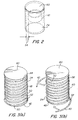
- FIG. 2 is a front isometric view of a DSC sub-assembly with a temperature controlled shield such as that shown in FIG. 1 ;
- FIG. 3(a) and FIG. 3(b) are side isometric views of a temperature controlled shield such as that shown in FIG. 2 ;
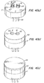
- FIG. 4(a) is a front isometric view of a DSC measuring system having two sub-assemblies such as shown in FIG. 2 .
- FIG. 4(b) shows measuring system of FIG. 4(a) having a metal block.
- FIG. 4(c) shows measuring system of FIG. 4(b) having an additional cover disposed on block;
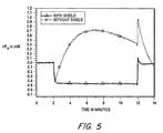
- FIG. 5 is a graph of heat flow of an empty measuring system of FIG.4(c) at 10 K/min heating from 350 K to 450 K.
- FIG.1 A schematic diagram of an embodiment of an improved differential scanning calorimeter (DSC) is shown in FIG.1 .
- a calorimeter 100 such as PerkinElmer's Diamond DSC may be used to incorporate the present teachings; however, other models may be used such as PerkinElmer's power compensated Pyris 1 DSC, PerkinElmer's DSC 7, or the like.
- the illustrated DSC has a metal base 2 located in an inner chamber 4 defined by an outer wall 5 which may be a heat shield. Metal base 2 may be connected to a cooling block (not shown in FIG.1 ). Support 6 on base 2 holds a reference cell 8 and a sample cell 10, each similar in volume and mass, and assembled with heating elements 12 and 14.
- Reference cell 8 and sample cell 10 each hold a sample in this case (not shown in FIG. 1 ), however, one of ordinary skill in the art would appreciate that it is possible to leave reference cell 8 empty, and/or that the reference may be data or a sample which may have known characteristics.
- Leads 16 connect cells 8 and 10 to a power source 18 to supply power to heating elements 12 and 14 in each of the cells, which may be independently controlled by a processor and/or computer 20.
- Computer 20 includes an interface 23 so that the user may provide/input specifications, and a memory 25 for storage, for example, a hard drive or random access memory.
- the illustrated heating elements 12 and 14 are driven by a power source 18, so cells 8 and 10 may be heated at varied or identical rates, which are controlled by the computer 20.
- the rate at which the temperature of the cells changes is referred to as the scan rate and can be specified by the user through the computer interface 23.
- the scan rate is between 0.01°C to 500°C/min, although other rates can be specified.
- a thermal effect measuring device 22 is connected to a sensor 27 that measures the difference in temperature between the two cells 8,10.
- Sensor 27 may be two or more separate sensors capable of independent analysis.
- the temperature control of the individual shields 24 is realized by thermal effect measuring device 22 having two independent control loops using a wire such as a platinum wire as thermometer and the resistive wire as heater. One controller measures the average temperature of the two shields and the second controller measures the temperature difference between both shields (as in the measuring portion of the power compensation DSC).
- the average temperatures of the two shields 24 follows a certain function of the temperature of the measuring system (the furnace) and are operated according to the different modes.
- Typical sensors include temperature measuring devices such as wire thermometers, thermocouples or semiconducting thermocouples.
- the temperature differential is continuously measured as the cells are being heated during a scan.
- the temperature differential data is then transmitted from thermal effect measuring device 22 to computer 20, where it is saved along with the time of the measurement in the computer memory 25.
- Output 75 provides data to user such as visual data showing graphs, alphanumeric symbols, and the like.
- thermal shield 24 which is shown as a cylinder placed around the cells. During adiabatic operation, the thermal shield 24 aids in reducing heat exchange between the cells and their surroundings.
- the temperature of thermal shield 24 is monitored by thermal effect measuring device 22 and sensors 27 which are mounted on thermal shield 24.
- Thermal shield 24 is connected to a heating and cooling device 26 which is operated by at least one controller 28.
- the signal to the controller 28 travels to and from computer 20.
- the output from cell measuring device 22 is sent to computer 20 and used to determine a signal to transmit to power source 34 and subsequently onto the controller 28.
- the temperature information is repeatedly stored in the computer memory 35 with the temperature differential between cells and the time of the measurement.
- the operating range for the calorimeter in terms of the temperature at which the cells and shield can be operated is -170°C to 730°C.
- the DSC may measure the temperature of thermal shield 24 and cells 8 and 10 with a temperature accuracy of ⁇ 0.1°C, and adjust the temperature thereof within the precision of ⁇ 0.1°C.
- the DSC may be modified with a wide range of DSC accessories and options from StepScan DSC and automatic gas switching to cooling devices and the wide variety of known sample pans.
- the illustrated thermal shield 24 is positioned around reference cell 8 and sample cells 10. The power to each of these thermal shields 24 is independently controlled by the output of computer 20. Thermal shield 24 is capable of generating heat, and is used to actively reduce temperature differentials between cells 8 and 10.
- the heating system is capable of heating cells 8 or 10 and the thermal shield(s) 24 and may comprise the same or different heating elements defined by a controller. Where one, two, three, four, or more heating elements are used, the heating elements may be commonly controlled or independently controlled by the user.
- the user can select between various operational modes, in which thermal shields 24 are not used or various levels of use in which thermal shields 24 are used by computer 20 to actively minimize the temperature differential between cells 8 and 10.
- Modes of operation of the calorimeter having quasi adiabatic thermal shields 24 include:
- the quasi adiabatic temperature controlled shield 24 is shown encompassing a cell, such as sample cell 10.
- Shield 24 is made of high thermal conducting material such as one or more of aluminium, copper, ceramic or silver to avoid temperature gradients across shield 24.
- the temperature gradient and the heat losses which are needed to allow fast cooling are defined by the connections (feet) of the shield (not shown in FIG. 2 ) and the temperature controlled heat sink at the base of the measuring system (not shown in FIG. 2 ).
- the connections (feet) are constructed of a metal or ceramic material to allow high temperature operation.
- Shield 24 comprises a thin walled (between 0.25 mm to 10 mm thick, preferably about 0.5 mm) cylinder.
- Gap 54 lies between cell 10 and thermal shield 24.
- the gap 54 has a width between 0.25 mm and 10 mm, and in some embodiments between about 0.5 mm to about 1.5 mm and yet in other embodiments about 1.0 mm to promote adiabatic processes.
- First cover 60 is shown disposed on top of thermal shield 24.
- thermal shield 24 in the shape of a cylinder is shown having top end 44, bottom end 46 and sidewall 48.
- First cover 60 is shown disposed on top of thermal shield 24.
- Sidewall 48 is covered with a dielectric layer 50, e.g., a glass or an alumina layer, to electrically isolate wires from the cylinder giving a very short response time.
- Sidewall 48 has an outer perimeter and is threaded, thus groove 52 extends around the outer perimeter.
- wire 40 is shown placed within groove 52 extending around the perimeter of thermal shield.
- wire 40 may be a thermometer or thermocouple disposed upon the sidewall 48 comprising a temperature resistive wire portion 54 and resistive wire portion 56 as a heater.
- wire 40 is capable of acting as temperature sensor. Both temperature resistive wire 54 and resistive wire 56 are wound around the outside of the cylinder covering a large area of sidewall 48 to realize a short response time for temperature control. To avoid contact between the heater and sensor wires, each is contained in separate parallel grooves and may be fixed in place with high temperature ceramic glue.
- Thermal resistant wire 54 is can be made of platinum. Although not shown in FIG. 3 , in the illustrated embodiment, the platinum wires are connected with gold braze to a platinum connector ribbon providing high temperature operation.
- a DSC measuring system having two sub-assemblies comprising a reference cell 8 and a sample cell 10.
- the subassemblies and circuitry is enclosed in metal base 2.
- Various leads 58 are shown entering the bottom portion of base 2 which are used to provide signals to and from the computer to the sensors and heaters positioned in the subassemblies (not shown in FIG. 4a )).
- Reference cell 8 and sample cell 10 are shown adjacent one another in the center of the apparatus.
- Thermal shields 24 surround reference cell 8 and sample cell 10 and extend up and out of metal base 2.
- FIG. 4(b) a DSC measuring system having the same features as FIG. 4(a) is shown; however, aluminium block 60 is placed upon metal base 12.
- Metal block 60 can be made of aluminium and contains two openings 62 positioned in the center of the block such that the block may be placed on metal base 2, and snugly surround reference cell 8 and sample cell 10, both having thermal shield 24.
- FIG. 4(c) shows a second cover 64 placed over block 60 such that openings 62 become covered.
- FIG. 5 shows a graph of heat flow of an empty measuring system at 10 K/min heating from 350 K to 450 K using temperature control shields surrounding reference cell and sample cell.
- the effect of the quasi adiabatic temperature controlled shield as operated as described herein on base-line straightness can be seen in FIG. 5 .
- the temperature control of the shields improves base-line straightness. In this case, the temperature of the shields closely followed the temperature of the measuring system.
- additional advanced control algorithms may be added to improve base-line straightness and noise level even further.
Landscapes
- Chemical & Material Sciences (AREA)
- Engineering & Computer Science (AREA)
- Combustion & Propulsion (AREA)
- Physics & Mathematics (AREA)
- General Physics & Mathematics (AREA)
- Chemical Kinetics & Catalysis (AREA)
- Health & Medical Sciences (AREA)
- Life Sciences & Earth Sciences (AREA)
- Analytical Chemistry (AREA)
- Biochemistry (AREA)
- General Health & Medical Sciences (AREA)
- Immunology (AREA)
- Pathology (AREA)
- Investigating Or Analyzing Materials Using Thermal Means (AREA)
Applications Claiming Priority (2)
| Application Number | Priority Date | Filing Date | Title |
|---|---|---|---|
| US11/054,755 US7371006B2 (en) | 2004-02-10 | 2005-02-10 | Differential scanning calorimeter (DSC) with temperature controlled furnace |
| EP06734839.1A EP1859258B1 (fr) | 2005-02-10 | 2006-02-10 | Calorimetre a compensation de puissance (dsc) comprenant un fourneau a temperature regulee |
Related Parent Applications (3)
| Application Number | Title | Priority Date | Filing Date |
|---|---|---|---|
| EP06734839.1 Division | 2006-02-10 | ||
| EP06734839.1A Division EP1859258B1 (fr) | 2005-02-10 | 2006-02-10 | Calorimetre a compensation de puissance (dsc) comprenant un fourneau a temperature regulee |
| EP06734839.1A Division-Into EP1859258B1 (fr) | 2005-02-10 | 2006-02-10 | Calorimetre a compensation de puissance (dsc) comprenant un fourneau a temperature regulee |
Publications (3)
| Publication Number | Publication Date |
|---|---|
| EP2290356A2 true EP2290356A2 (fr) | 2011-03-02 |
| EP2290356A3 EP2290356A3 (fr) | 2012-03-14 |
| EP2290356B1 EP2290356B1 (fr) | 2014-06-25 |
Family
ID=36579785
Family Applications (2)
| Application Number | Title | Priority Date | Filing Date |
|---|---|---|---|
| EP06734839.1A Expired - Lifetime EP1859258B1 (fr) | 2005-02-10 | 2006-02-10 | Calorimetre a compensation de puissance (dsc) comprenant un fourneau a temperature regulee |
| EP10189959.9A Expired - Lifetime EP2290356B1 (fr) | 2005-02-10 | 2006-02-10 | Calorimètre à balayage différentiel doté d'un four à température contrôlée |
Family Applications Before (1)
| Application Number | Title | Priority Date | Filing Date |
|---|---|---|---|
| EP06734839.1A Expired - Lifetime EP1859258B1 (fr) | 2005-02-10 | 2006-02-10 | Calorimetre a compensation de puissance (dsc) comprenant un fourneau a temperature regulee |
Country Status (5)
| Country | Link |
|---|---|
| US (3) | US7371006B2 (fr) |
| EP (2) | EP1859258B1 (fr) |
| JP (1) | JP4579993B2 (fr) |
| CA (1) | CA2597405C (fr) |
| WO (1) | WO2006086708A1 (fr) |
Families Citing this family (40)
| Publication number | Priority date | Publication date | Assignee | Title |
|---|---|---|---|---|
| CZ300882B6 (cs) * | 2002-11-13 | 2009-09-02 | Rwe Transgas Net, S.R.O. | Zpusob merení výhrevnosti plynu a meridlo pro provádení tohoto zpusobu |
| US6860632B2 (en) * | 2003-07-28 | 2005-03-01 | Perkinelmer Instruments Llc | Instrument material holder and method of fabrication thereof |
| JP4116526B2 (ja) * | 2003-11-18 | 2008-07-09 | エスアイアイ・ナノテクノロジー株式会社 | 第二のヒーターを備えた示差走査熱量計 |
| FR2886730B1 (fr) * | 2005-06-02 | 2007-07-27 | Inst Francais Du Petrole | Methode d'analyse de la cinetique de formation d'hydrates de gaz dans des fluides |
| JP4611154B2 (ja) * | 2005-09-01 | 2011-01-12 | エスアイアイ・ナノテクノロジー株式会社 | 熱流束型示差走査熱量計 |
| JP4836595B2 (ja) * | 2006-02-13 | 2011-12-14 | エスアイアイ・ナノテクノロジー株式会社 | 示差走査熱量測定における凝固点の特定方法および温度較正方法 |
| US7470057B2 (en) * | 2006-08-24 | 2008-12-30 | Waters Investments Limited | Differential scanning calorimeter sensor and method |
| JP4831487B2 (ja) * | 2006-12-21 | 2011-12-07 | エスアイアイ・ナノテクノロジー株式会社 | 示差走査熱量計 |
| JP5143897B2 (ja) * | 2007-05-16 | 2013-02-13 | エナジエテイツク・ジエノミクス・コーポレイシヨン | 大型アレイ式示差走査熱量計のdsc測定装置 |
| US8021039B2 (en) * | 2007-11-07 | 2011-09-20 | Frank Amato | Quality control material monitor |
| WO2009111475A2 (fr) * | 2008-03-03 | 2009-09-11 | Heatflow Technologies, Inc. | Procédés et systèmes pour exécuter des amplifications en chaîne par polymérase dans un flux de chaleur |
| DE602008005427D1 (de) * | 2008-06-13 | 2011-04-21 | Mettler Toledo Ag | Wärmeanalyseinstrument mit dynamischer Leistungskompensation |
| KR100961065B1 (ko) * | 2008-09-29 | 2010-06-01 | 한국전력공사 | 송전애자용 열충격 모의시험장치 |
| US8307843B2 (en) * | 2009-01-21 | 2012-11-13 | Tescom Corporation | Temperature-controlled pressure regulators |
| EP2214005B1 (fr) | 2009-02-03 | 2019-09-18 | Mettler-Toledo GmbH | Instrument thermo-analytique |
| US8147133B2 (en) * | 2009-05-26 | 2012-04-03 | The United States Of America As Represented By The Secretary Of The Navy | Top loaded twin cell calorimeter system with removable reference |
| US8926172B2 (en) * | 2009-07-07 | 2015-01-06 | Frank Leu Wu | Differential adiabatic compensation calorimeter and methods of operation |
| CH702328A2 (de) * | 2009-12-01 | 2011-06-15 | Acl Instr Ag | Wärmefluss-Kalorimeter. |
| DE102009056338B4 (de) | 2009-12-01 | 2022-01-13 | Jaroslaw Kita | Keramischer DSC-Chip |
| US20110164652A1 (en) * | 2010-01-05 | 2011-07-07 | Refalo Lee A | Differential Thermoelectric Cooler Calorimeter |
| JP5709160B2 (ja) * | 2010-03-29 | 2015-04-30 | 株式会社日立ハイテクサイエンス | 熱分析装置 |
| JP2012078146A (ja) * | 2010-09-30 | 2012-04-19 | Shimadzu Corp | 示差走査熱量計 |
| WO2012109383A2 (fr) * | 2011-02-08 | 2012-08-16 | University Of Louisville Research Foundation, Inc. | Procédé de détermination de caractéristiques de liaison d'un médicament candidat à une protéine |
| US9857241B2 (en) * | 2012-09-04 | 2018-01-02 | Waters Technologies Corporation | Quasiadiabetic differential scanning calorimeter |
| US9593988B1 (en) * | 2013-07-23 | 2017-03-14 | Calmetrix, Inc. | Systems and methods of thermal energy measurement |
| CN103743775B (zh) * | 2013-10-22 | 2016-04-20 | 南京大学 | 一种可与其它显微结构表征技术联用的冷热台型高速量热仪 |
| US10054558B2 (en) * | 2013-12-27 | 2018-08-21 | Owens-Brockway Glass Container Inc. | System and method for testing thermal properties of a container |
| CN104535611B (zh) * | 2015-01-16 | 2017-04-26 | 中国计量科学研究院 | 固体比热容计量标准装置和测量方法 |
| CN104914129B (zh) * | 2015-04-29 | 2017-10-10 | 河北普莱斯曼金刚石科技有限公司 | 一种金刚石膜热导率检测方法 |
| CN105588854B (zh) * | 2016-02-26 | 2018-12-07 | 中国计量学院 | 快速温度扫描筛选量热仪 |
| DE102016117754B4 (de) * | 2016-09-21 | 2019-03-21 | Netzsch-Gerätebau GmbH | Verfahren zum Kalibrieren einer Vorrichtung zur thermischen Analyse von Proben |
| EP3396392B1 (fr) * | 2017-04-26 | 2020-11-04 | ElectDis AB | Appareil et procédé de détermination d'une valeur de puissance d'une cible |
| EP3676603B1 (fr) | 2017-08-31 | 2026-03-04 | Waters Technologies Corporation | Cellule de calorimètre hybride |
| US11474054B2 (en) * | 2018-10-22 | 2022-10-18 | Equistar Chemicals, Lp | Temperature control apparatuses and methods |
| CN110297011B (zh) * | 2019-08-12 | 2021-10-29 | 杭州仰仪科技有限公司 | 一种准绝热快速筛选量热方法 |
| CN110988035B (zh) * | 2019-12-26 | 2025-03-18 | 沈阳化工研究院有限公司 | 一种利用参比量热测试连续流反应热方法及装置 |
| CN111780895A (zh) * | 2020-07-06 | 2020-10-16 | 中国原子能科学研究院 | 量热装置 |
| US11047748B1 (en) * | 2020-08-14 | 2021-06-29 | Frank L. Wu | Adiabatic power compensation differential scanning calorimeter |
| NL2028305B1 (en) * | 2021-05-27 | 2022-12-08 | Veridis Tech B V | Massive differential scanning calorimetry analysis method and apparatus |
| CN116929602A (zh) * | 2022-03-30 | 2023-10-24 | 北京正朗科技发展有限公司 | 孪生对称式量热仪 |
Citations (3)
| Publication number | Priority date | Publication date | Assignee | Title |
|---|---|---|---|---|
| US3263484A (en) | 1962-04-04 | 1966-08-02 | Perkin Elmer Corp | Differential microcalorimeter |
| US5475505A (en) | 1993-10-20 | 1995-12-12 | Xerox Corporation | Canted platen input scanner |
| US6530686B1 (en) | 1997-12-01 | 2003-03-11 | Seiko Instruments Inc. | Differential scanning calorimeter having low drift and high response characteristics |
Family Cites Families (30)
| Publication number | Priority date | Publication date | Assignee | Title |
|---|---|---|---|---|
| US3319456A (en) * | 1964-02-07 | 1967-05-16 | Gen Electric | Quantitative differential thermal analysis apparatus |
| US3667279A (en) * | 1969-10-08 | 1972-06-06 | Dow Chemical Co | Differential thermal analysis cell assembly |
| US3685344A (en) * | 1969-10-08 | 1972-08-22 | Dow Chemical Co | Differential thermal analysis cell assembly |
| US3791202A (en) * | 1972-02-23 | 1974-02-12 | B Zaslavsky | Differential microcalorimeter |
| JPS5230495A (en) * | 1975-09-03 | 1977-03-08 | Rigaku Denki Kk | Thermal analysis apparatus |
| DE3529489A1 (de) * | 1985-08-16 | 1987-02-26 | Max Planck Gesellschaft | Verfahren und einrichtung zum bestimmen der waermekapazitaet einer probe |
| FR2592159B1 (fr) * | 1985-12-19 | 1988-07-22 | Commissariat Energie Atomique | Calorimetre quasi-adiabatique servant a mesurer l'energie transportee par un rayonnement. |
| US5098196A (en) | 1991-01-04 | 1992-03-24 | The Perkin-Elmer Corporation | Circuit for heating and sensing with a single element |
| JPH04348265A (ja) * | 1991-05-24 | 1992-12-03 | Rigaku Corp | 均熱帯を備えた示差型熱分析装置 |
| IT1252798B (it) | 1991-09-13 | 1995-06-28 | Consiglio Nazionale Ricerche | Calorimetro per misure tempo-temperatura di resine termoindurenti (thermosets). |
| US5288147A (en) * | 1992-11-09 | 1994-02-22 | Ta Instruments, Inc. | Thermopile differential thermal analysis sensor |
| US5813763A (en) * | 1996-10-11 | 1998-09-29 | Microcal Incorporated | Ultrasensitive differential microcalorimeter |
| US5806979A (en) * | 1996-11-19 | 1998-09-15 | Iowa State University Research Foundation, Inc. | Calorimetric system and method |
| JP3370581B2 (ja) * | 1997-11-28 | 2003-01-27 | セイコーインスツルメンツ株式会社 | 高速熱分析装置 |
| US5988875A (en) * | 1997-12-19 | 1999-11-23 | The United States Of America As Respresented By The Department Of Health And Human Services | Calorimeter and method for simultaneous measurement of thermal conductivity and specific heat of fluids |
| JP3370592B2 (ja) * | 1998-01-19 | 2003-01-27 | セイコーインスツルメンツ株式会社 | 示差熱分析装置 |
| US6572263B1 (en) * | 1998-04-14 | 2003-06-03 | Westinghouse Savannah River Company | Dry calorimeter |
| WO1999060356A1 (fr) | 1998-05-20 | 1999-11-25 | Consiglio Nazionale Delle Ricerche | Procede et dispositif permettant de reguler un flux thermique a des fins de calorimetrie, de protection adiabatique, de reglage fin de la temperature, etc. |
| JP2000074863A (ja) * | 1998-08-27 | 2000-03-14 | Terametsukusu Kk | 液体試料用高圧示差走査熱量測定装置 |
| US6238085B1 (en) * | 1998-12-31 | 2001-05-29 | Honeywell International Inc. | Differential thermal analysis sensor |
| WO2001009597A1 (fr) * | 1999-07-28 | 2001-02-08 | Microcal, Llc | Instruments calorimetriques par perturbations de pression et procede s'y rapportant |
| US6561692B2 (en) * | 2000-03-23 | 2003-05-13 | Ta Instruments-Waters Llc | Differential scanning calorimeter |
| US6431747B1 (en) * | 2000-03-23 | 2002-08-13 | Ta Instruments, Inc. | Heat flux differential scanning calorimeter sensor |
| US6523998B1 (en) * | 2001-01-26 | 2003-02-25 | Ta Instruments, Inc. | Thermal analysis assembly with distributed resistance and integral flange for mounting various cooling devices |
| US6843595B2 (en) * | 2001-01-26 | 2005-01-18 | Waters Investment Limited | Differential scanning calorimeter accounting for heat leakage |
| US6641300B1 (en) * | 2001-01-29 | 2003-11-04 | Waters Investment, Ltd. | Differential scanning calorimeter |
| US7141210B2 (en) | 2002-04-01 | 2006-11-28 | Palo Alto Research Center Incorporated | Apparatus and method for a nanocalorimeter for detecting chemical reactions |
| JP4617304B2 (ja) * | 2003-07-10 | 2011-01-26 | ネッチ−ゲラーエーテバオ ゲーエムベーハー | 低熱慣性走査断熱熱量計 |
| US6988826B2 (en) * | 2004-05-17 | 2006-01-24 | General Electric Company | Nano-calorimeter device and associated methods of fabrication and use |
| US7578613B2 (en) * | 2006-09-14 | 2009-08-25 | Waters Investments Limited | Modulated differential scanning calorimeter solvent loss calibration apparatus and method |
-
2005
- 2005-02-10 US US11/054,755 patent/US7371006B2/en not_active Expired - Lifetime
-
2006
- 2006-02-10 EP EP06734839.1A patent/EP1859258B1/fr not_active Expired - Lifetime
- 2006-02-10 EP EP10189959.9A patent/EP2290356B1/fr not_active Expired - Lifetime
- 2006-02-10 WO PCT/US2006/004884 patent/WO2006086708A1/fr not_active Ceased
- 2006-02-10 JP JP2007555278A patent/JP4579993B2/ja not_active Expired - Fee Related
- 2006-02-10 CA CA2597405A patent/CA2597405C/fr not_active Expired - Lifetime
-
2007
- 2007-10-31 US US11/931,163 patent/US7448796B2/en not_active Expired - Lifetime
-
2008
- 2008-10-16 US US12/252,671 patent/US7677795B2/en not_active Expired - Fee Related
Patent Citations (3)
| Publication number | Priority date | Publication date | Assignee | Title |
|---|---|---|---|---|
| US3263484A (en) | 1962-04-04 | 1966-08-02 | Perkin Elmer Corp | Differential microcalorimeter |
| US5475505A (en) | 1993-10-20 | 1995-12-12 | Xerox Corporation | Canted platen input scanner |
| US6530686B1 (en) | 1997-12-01 | 2003-03-11 | Seiko Instruments Inc. | Differential scanning calorimeter having low drift and high response characteristics |
Also Published As
| Publication number | Publication date |
|---|---|
| EP2290356B1 (fr) | 2014-06-25 |
| CA2597405C (fr) | 2012-06-12 |
| WO2006086708A1 (fr) | 2006-08-17 |
| JP4579993B2 (ja) | 2010-11-10 |
| US7448796B2 (en) | 2008-11-11 |
| US20050190813A1 (en) | 2005-09-01 |
| EP1859258B1 (fr) | 2014-11-19 |
| EP1859258A1 (fr) | 2007-11-28 |
| US7677795B2 (en) | 2010-03-16 |
| US20090034579A1 (en) | 2009-02-05 |
| JP2008530560A (ja) | 2008-08-07 |
| US7371006B2 (en) | 2008-05-13 |
| US20080049810A1 (en) | 2008-02-28 |
| CA2597405A1 (fr) | 2006-08-17 |
| EP2290356A3 (fr) | 2012-03-14 |
Similar Documents
| Publication | Publication Date | Title |
|---|---|---|
| US7448796B2 (en) | Differential scanning calorimeter (DSC) with temperature controlled furnace | |
| Privalov et al. | Precision scanning microcalorimeter for the study of liquids | |
| US7255475B2 (en) | Thermometry probe calibration method | |
| US20120003726A1 (en) | Apparatus and method for calibration of non-contact thermal sensors | |
| JP5642525B2 (ja) | 示差走査熱量計 | |
| US20110164651A1 (en) | Open-loop vertical drywell gradient correction system and method | |
| Suga et al. | An Automatic Adiabatic Calorimeter for Low Temperatures. The Heat Capacity of Standard Benzoic Acid | |
| US6530686B1 (en) | Differential scanning calorimeter having low drift and high response characteristics | |
| EP2893333B1 (fr) | Calorimètre différentiel quasi-adiabatique à balayage | |
| JP2006145446A (ja) | 熱伝導率測定装置及び熱伝導率の測定方法 | |
| CN117849100A (zh) | 用于差示扫描量热仪的校准方法 | |
| US5884235A (en) | Non-contact, zero-flux temperature sensor | |
| JP2006515672A (ja) | 精密制御型サーモスタット | |
| US20030026319A1 (en) | Differential scanning calorimeter | |
| US4415534A (en) | Apparatus for analyzing biological liquids | |
| JPH07198500A (ja) | 表面温度測定方法 | |
| WO2005068066A1 (fr) | Regulateur de temperature et dispositif de cristallisation de proteines comprenant ce regulateur | |
| WO2006020770A2 (fr) | Capteur de temperature a vitesse de decroissance de la fluorescence compensee thermiquement et son procede d'utilisation | |
| JP2002181751A (ja) | 示差走査熱量計 | |
| JPS5923369B2 (ja) | 零位法熱流計 | |
| Mokdad et al. | A Self-Validation Method for High-Temperature Thermocouples Under Oxidizing Atmospheres | |
| US20250293069A1 (en) | Modeling substrate temperatures | |
| KR920009890B1 (ko) | 점도 측정용 항온조의 온도 제어수단 | |
| KR0165463B1 (ko) | 웨이퍼 온도 측정 방법 | |
| JP2008026179A (ja) | 輻射熱センサーと輻射熱の測定方法 |
Legal Events
| Date | Code | Title | Description |
|---|---|---|---|
| PUAI | Public reference made under article 153(3) epc to a published international application that has entered the european phase |
Free format text: ORIGINAL CODE: 0009012 |
|
| AC | Divisional application: reference to earlier application |
Ref document number: 1859258 Country of ref document: EP Kind code of ref document: P |
|
| AK | Designated contracting states |
Kind code of ref document: A2 Designated state(s): AT BE BG CH CY CZ DE DK EE ES FI FR GB GR HU IE IS IT LI LT LU LV MC NL PL PT RO SE SI SK TR |
|
| RAP1 | Party data changed (applicant data changed or rights of an application transferred) |
Owner name: PERKINELMER HEALTH SCIENCES, INC. |
|
| PUAL | Search report despatched |
Free format text: ORIGINAL CODE: 0009013 |
|
| AK | Designated contracting states |
Kind code of ref document: A3 Designated state(s): AT BE BG CH CY CZ DE DK EE ES FI FR GB GR HU IE IS IT LI LT LU LV MC NL PL PT RO SE SI SK TR |
|
| RIC1 | Information provided on ipc code assigned before grant |
Ipc: G01N 25/48 20060101AFI20120207BHEP Ipc: G01K 17/08 20060101ALI20120207BHEP |
|
| 17P | Request for examination filed |
Effective date: 20120516 |
|
| GRAP | Despatch of communication of intention to grant a patent |
Free format text: ORIGINAL CODE: EPIDOSNIGR1 |
|
| INTG | Intention to grant announced |
Effective date: 20131121 |
|
| GRAJ | Information related to disapproval of communication of intention to grant by the applicant or resumption of examination proceedings by the epo deleted |
Free format text: ORIGINAL CODE: EPIDOSDIGR1 |
|
| GRAP | Despatch of communication of intention to grant a patent |
Free format text: ORIGINAL CODE: EPIDOSNIGR1 |
|
| GRAP | Despatch of communication of intention to grant a patent |
Free format text: ORIGINAL CODE: EPIDOSNIGR1 |
|
| INTG | Intention to grant announced |
Effective date: 20140401 |
|
| INTG | Intention to grant announced |
Effective date: 20140410 |
|
| GRAS | Grant fee paid |
Free format text: ORIGINAL CODE: EPIDOSNIGR3 |
|
| GRAA | (expected) grant |
Free format text: ORIGINAL CODE: 0009210 |
|
| AC | Divisional application: reference to earlier application |
Ref document number: 1859258 Country of ref document: EP Kind code of ref document: P |
|
| AK | Designated contracting states |
Kind code of ref document: B1 Designated state(s): AT BE BG CH CY CZ DE DK EE ES FI FR GB GR HU IE IS IT LI LT LU LV MC NL PL PT RO SE SI SK TR |
|
| REG | Reference to a national code |
Ref country code: GB Ref legal event code: FG4D |
|
| REG | Reference to a national code |
Ref country code: CH Ref legal event code: EP |
|
| REG | Reference to a national code |
Ref country code: AT Ref legal event code: REF Ref document number: 674984 Country of ref document: AT Kind code of ref document: T Effective date: 20140715 |
|
| REG | Reference to a national code |
Ref country code: IE Ref legal event code: FG4D |
|
| REG | Reference to a national code |
Ref country code: DE Ref legal event code: R096 Ref document number: 602006042093 Country of ref document: DE Effective date: 20140731 |
|
| PG25 | Lapsed in a contracting state [announced via postgrant information from national office to epo] |
Ref country code: FI Free format text: LAPSE BECAUSE OF FAILURE TO SUBMIT A TRANSLATION OF THE DESCRIPTION OR TO PAY THE FEE WITHIN THE PRESCRIBED TIME-LIMIT Effective date: 20140625 Ref country code: CY Free format text: LAPSE BECAUSE OF FAILURE TO SUBMIT A TRANSLATION OF THE DESCRIPTION OR TO PAY THE FEE WITHIN THE PRESCRIBED TIME-LIMIT Effective date: 20140625 Ref country code: GR Free format text: LAPSE BECAUSE OF FAILURE TO SUBMIT A TRANSLATION OF THE DESCRIPTION OR TO PAY THE FEE WITHIN THE PRESCRIBED TIME-LIMIT Effective date: 20140926 Ref country code: LT Free format text: LAPSE BECAUSE OF FAILURE TO SUBMIT A TRANSLATION OF THE DESCRIPTION OR TO PAY THE FEE WITHIN THE PRESCRIBED TIME-LIMIT Effective date: 20140625 |
|
| REG | Reference to a national code |
Ref country code: AT Ref legal event code: MK05 Ref document number: 674984 Country of ref document: AT Kind code of ref document: T Effective date: 20140625 |
|
| REG | Reference to a national code |
Ref country code: NL Ref legal event code: VDEP Effective date: 20140625 |
|
| REG | Reference to a national code |
Ref country code: LT Ref legal event code: MG4D |
|
| PG25 | Lapsed in a contracting state [announced via postgrant information from national office to epo] |
Ref country code: LV Free format text: LAPSE BECAUSE OF FAILURE TO SUBMIT A TRANSLATION OF THE DESCRIPTION OR TO PAY THE FEE WITHIN THE PRESCRIBED TIME-LIMIT Effective date: 20140625 Ref country code: SE Free format text: LAPSE BECAUSE OF FAILURE TO SUBMIT A TRANSLATION OF THE DESCRIPTION OR TO PAY THE FEE WITHIN THE PRESCRIBED TIME-LIMIT Effective date: 20140625 |
|
| PG25 | Lapsed in a contracting state [announced via postgrant information from national office to epo] |
Ref country code: EE Free format text: LAPSE BECAUSE OF FAILURE TO SUBMIT A TRANSLATION OF THE DESCRIPTION OR TO PAY THE FEE WITHIN THE PRESCRIBED TIME-LIMIT Effective date: 20140625 Ref country code: ES Free format text: LAPSE BECAUSE OF FAILURE TO SUBMIT A TRANSLATION OF THE DESCRIPTION OR TO PAY THE FEE WITHIN THE PRESCRIBED TIME-LIMIT Effective date: 20140625 Ref country code: PT Free format text: LAPSE BECAUSE OF FAILURE TO SUBMIT A TRANSLATION OF THE DESCRIPTION OR TO PAY THE FEE WITHIN THE PRESCRIBED TIME-LIMIT Effective date: 20141027 Ref country code: CZ Free format text: LAPSE BECAUSE OF FAILURE TO SUBMIT A TRANSLATION OF THE DESCRIPTION OR TO PAY THE FEE WITHIN THE PRESCRIBED TIME-LIMIT Effective date: 20140625 Ref country code: RO Free format text: LAPSE BECAUSE OF FAILURE TO SUBMIT A TRANSLATION OF THE DESCRIPTION OR TO PAY THE FEE WITHIN THE PRESCRIBED TIME-LIMIT Effective date: 20140625 Ref country code: SK Free format text: LAPSE BECAUSE OF FAILURE TO SUBMIT A TRANSLATION OF THE DESCRIPTION OR TO PAY THE FEE WITHIN THE PRESCRIBED TIME-LIMIT Effective date: 20140625 |
|
| PG25 | Lapsed in a contracting state [announced via postgrant information from national office to epo] |
Ref country code: IS Free format text: LAPSE BECAUSE OF FAILURE TO SUBMIT A TRANSLATION OF THE DESCRIPTION OR TO PAY THE FEE WITHIN THE PRESCRIBED TIME-LIMIT Effective date: 20141025 Ref country code: AT Free format text: LAPSE BECAUSE OF FAILURE TO SUBMIT A TRANSLATION OF THE DESCRIPTION OR TO PAY THE FEE WITHIN THE PRESCRIBED TIME-LIMIT Effective date: 20140625 Ref country code: NL Free format text: LAPSE BECAUSE OF FAILURE TO SUBMIT A TRANSLATION OF THE DESCRIPTION OR TO PAY THE FEE WITHIN THE PRESCRIBED TIME-LIMIT Effective date: 20140625 Ref country code: PL Free format text: LAPSE BECAUSE OF FAILURE TO SUBMIT A TRANSLATION OF THE DESCRIPTION OR TO PAY THE FEE WITHIN THE PRESCRIBED TIME-LIMIT Effective date: 20140625 |
|
| REG | Reference to a national code |
Ref country code: DE Ref legal event code: R097 Ref document number: 602006042093 Country of ref document: DE |
|
| PG25 | Lapsed in a contracting state [announced via postgrant information from national office to epo] |
Ref country code: DK Free format text: LAPSE BECAUSE OF FAILURE TO SUBMIT A TRANSLATION OF THE DESCRIPTION OR TO PAY THE FEE WITHIN THE PRESCRIBED TIME-LIMIT Effective date: 20140625 Ref country code: IT Free format text: LAPSE BECAUSE OF FAILURE TO SUBMIT A TRANSLATION OF THE DESCRIPTION OR TO PAY THE FEE WITHIN THE PRESCRIBED TIME-LIMIT Effective date: 20140625 |
|
| PLBE | No opposition filed within time limit |
Free format text: ORIGINAL CODE: 0009261 |
|
| STAA | Information on the status of an ep patent application or granted ep patent |
Free format text: STATUS: NO OPPOSITION FILED WITHIN TIME LIMIT |
|
| 26N | No opposition filed |
Effective date: 20150326 |
|
| PG25 | Lapsed in a contracting state [announced via postgrant information from national office to epo] |
Ref country code: BE Free format text: LAPSE BECAUSE OF FAILURE TO SUBMIT A TRANSLATION OF THE DESCRIPTION OR TO PAY THE FEE WITHIN THE PRESCRIBED TIME-LIMIT Effective date: 20140625 |
|
| PG25 | Lapsed in a contracting state [announced via postgrant information from national office to epo] |
Ref country code: LU Free format text: LAPSE BECAUSE OF FAILURE TO SUBMIT A TRANSLATION OF THE DESCRIPTION OR TO PAY THE FEE WITHIN THE PRESCRIBED TIME-LIMIT Effective date: 20150210 |
|
| REG | Reference to a national code |
Ref country code: CH Ref legal event code: PL |
|
| PG25 | Lapsed in a contracting state [announced via postgrant information from national office to epo] |
Ref country code: MC Free format text: LAPSE BECAUSE OF FAILURE TO SUBMIT A TRANSLATION OF THE DESCRIPTION OR TO PAY THE FEE WITHIN THE PRESCRIBED TIME-LIMIT Effective date: 20140625 Ref country code: LI Free format text: LAPSE BECAUSE OF NON-PAYMENT OF DUE FEES Effective date: 20150228 Ref country code: CH Free format text: LAPSE BECAUSE OF NON-PAYMENT OF DUE FEES Effective date: 20150228 |
|
| REG | Reference to a national code |
Ref country code: IE Ref legal event code: MM4A |
|
| REG | Reference to a national code |
Ref country code: FR Ref legal event code: ST Effective date: 20151030 |
|
| PG25 | Lapsed in a contracting state [announced via postgrant information from national office to epo] |
Ref country code: SI Free format text: LAPSE BECAUSE OF FAILURE TO SUBMIT A TRANSLATION OF THE DESCRIPTION OR TO PAY THE FEE WITHIN THE PRESCRIBED TIME-LIMIT Effective date: 20140625 |
|
| PG25 | Lapsed in a contracting state [announced via postgrant information from national office to epo] |
Ref country code: IE Free format text: LAPSE BECAUSE OF NON-PAYMENT OF DUE FEES Effective date: 20150210 |
|
| PG25 | Lapsed in a contracting state [announced via postgrant information from national office to epo] |
Ref country code: FR Free format text: LAPSE BECAUSE OF NON-PAYMENT OF DUE FEES Effective date: 20150302 |
|
| PG25 | Lapsed in a contracting state [announced via postgrant information from national office to epo] |
Ref country code: HU Free format text: LAPSE BECAUSE OF FAILURE TO SUBMIT A TRANSLATION OF THE DESCRIPTION OR TO PAY THE FEE WITHIN THE PRESCRIBED TIME-LIMIT; INVALID AB INITIO Effective date: 20060210 Ref country code: BG Free format text: LAPSE BECAUSE OF FAILURE TO SUBMIT A TRANSLATION OF THE DESCRIPTION OR TO PAY THE FEE WITHIN THE PRESCRIBED TIME-LIMIT Effective date: 20140625 |
|
| PG25 | Lapsed in a contracting state [announced via postgrant information from national office to epo] |
Ref country code: TR Free format text: LAPSE BECAUSE OF FAILURE TO SUBMIT A TRANSLATION OF THE DESCRIPTION OR TO PAY THE FEE WITHIN THE PRESCRIBED TIME-LIMIT Effective date: 20140625 |
|
| PGFP | Annual fee paid to national office [announced via postgrant information from national office to epo] |
Ref country code: GB Payment date: 20221222 Year of fee payment: 18 |
|
| PGFP | Annual fee paid to national office [announced via postgrant information from national office to epo] |
Ref country code: DE Payment date: 20221220 Year of fee payment: 18 |
|
| P01 | Opt-out of the competence of the unified patent court (upc) registered |
Effective date: 20230601 |
|
| REG | Reference to a national code |
Ref country code: DE Ref legal event code: R119 Ref document number: 602006042093 Country of ref document: DE |
|
| GBPC | Gb: european patent ceased through non-payment of renewal fee |
Effective date: 20240210 |
|
| PG25 | Lapsed in a contracting state [announced via postgrant information from national office to epo] |
Ref country code: DE Free format text: LAPSE BECAUSE OF NON-PAYMENT OF DUE FEES Effective date: 20240903 |
|
| PG25 | Lapsed in a contracting state [announced via postgrant information from national office to epo] |
Ref country code: GB Free format text: LAPSE BECAUSE OF NON-PAYMENT OF DUE FEES Effective date: 20240210 |
|
| PG25 | Lapsed in a contracting state [announced via postgrant information from national office to epo] |
Ref country code: GB Free format text: LAPSE BECAUSE OF NON-PAYMENT OF DUE FEES Effective date: 20240210 Ref country code: DE Free format text: LAPSE BECAUSE OF NON-PAYMENT OF DUE FEES Effective date: 20240903 |