EP2290433A1 - Lunettes de lecture éclairantes - Google Patents
Lunettes de lecture éclairantes Download PDFInfo
- Publication number
- EP2290433A1 EP2290433A1 EP10181593A EP10181593A EP2290433A1 EP 2290433 A1 EP2290433 A1 EP 2290433A1 EP 10181593 A EP10181593 A EP 10181593A EP 10181593 A EP10181593 A EP 10181593A EP 2290433 A1 EP2290433 A1 EP 2290433A1
- Authority
- EP
- European Patent Office
- Prior art keywords
- light
- housing
- lens
- blinder
- light source
- Prior art date
- Legal status (The legal status is an assumption and is not a legal conclusion. Google has not performed a legal analysis and makes no representation as to the accuracy of the status listed.)
- Granted
Links
- 239000011521 glass Substances 0.000 title abstract description 79
- 230000004313 glare Effects 0.000 claims abstract description 9
- 208000003464 asthenopia Diseases 0.000 claims abstract description 4
- 125000006850 spacer group Chemical group 0.000 description 17
- 239000000463 material Substances 0.000 description 14
- 239000000835 fiber Substances 0.000 description 9
- 230000008901 benefit Effects 0.000 description 8
- 230000007246 mechanism Effects 0.000 description 8
- 229910052751 metal Inorganic materials 0.000 description 8
- 239000002184 metal Substances 0.000 description 8
- 230000004438 eyesight Effects 0.000 description 7
- 230000002093 peripheral effect Effects 0.000 description 5
- 229920003023 plastic Polymers 0.000 description 5
- 230000000694 effects Effects 0.000 description 3
- 210000003128 head Anatomy 0.000 description 3
- 230000003247 decreasing effect Effects 0.000 description 2
- 230000007547 defect Effects 0.000 description 2
- 210000003811 finger Anatomy 0.000 description 2
- 238000012986 modification Methods 0.000 description 2
- 230000004048 modification Effects 0.000 description 2
- 239000013307 optical fiber Substances 0.000 description 2
- 239000012858 resilient material Substances 0.000 description 2
- 210000003813 thumb Anatomy 0.000 description 2
- 229910002601 GaN Inorganic materials 0.000 description 1
- JMASRVWKEDWRBT-UHFFFAOYSA-N Gallium nitride Chemical compound [Ga]#N JMASRVWKEDWRBT-UHFFFAOYSA-N 0.000 description 1
- 206010020675 Hypermetropia Diseases 0.000 description 1
- 229920000122 acrylonitrile butadiene styrene Polymers 0.000 description 1
- 230000009471 action Effects 0.000 description 1
- 230000004430 ametropia Effects 0.000 description 1
- 230000008859 change Effects 0.000 description 1
- 150000001875 compounds Chemical class 0.000 description 1
- 238000010276 construction Methods 0.000 description 1
- 229910052738 indium Inorganic materials 0.000 description 1
- APFVFJFRJDLVQX-UHFFFAOYSA-N indium atom Chemical compound [In] APFVFJFRJDLVQX-UHFFFAOYSA-N 0.000 description 1
- 230000002452 interceptive effect Effects 0.000 description 1
- 238000002955 isolation Methods 0.000 description 1
- 239000003562 lightweight material Substances 0.000 description 1
- VIKNJXKGJWUCNN-XGXHKTLJSA-N norethisterone Chemical compound O=C1CC[C@@H]2[C@H]3CC[C@](C)([C@](CC4)(O)C#C)[C@@H]4[C@@H]3CCC2=C1 VIKNJXKGJWUCNN-XGXHKTLJSA-N 0.000 description 1
- 238000010079 rubber tapping Methods 0.000 description 1
- 239000007787 solid Substances 0.000 description 1
- 229910001220 stainless steel Inorganic materials 0.000 description 1
- 239000010935 stainless steel Substances 0.000 description 1
Images


Classifications
-
- F—MECHANICAL ENGINEERING; LIGHTING; HEATING; WEAPONS; BLASTING
- F21—LIGHTING
- F21V—FUNCTIONAL FEATURES OR DETAILS OF LIGHTING DEVICES OR SYSTEMS THEREOF; STRUCTURAL COMBINATIONS OF LIGHTING DEVICES WITH OTHER ARTICLES, NOT OTHERWISE PROVIDED FOR
- F21V21/00—Supporting, suspending, or attaching arrangements for lighting devices; Hand grips
- F21V21/08—Devices for easy attachment to any desired place, e.g. clip, clamp, magnet
- F21V21/084—Head fittings
-
- F—MECHANICAL ENGINEERING; LIGHTING; HEATING; WEAPONS; BLASTING
- F21—LIGHTING
- F21V—FUNCTIONAL FEATURES OR DETAILS OF LIGHTING DEVICES OR SYSTEMS THEREOF; STRUCTURAL COMBINATIONS OF LIGHTING DEVICES WITH OTHER ARTICLES, NOT OTHERWISE PROVIDED FOR
- F21V21/00—Supporting, suspending, or attaching arrangements for lighting devices; Hand grips
- F21V21/08—Devices for easy attachment to any desired place, e.g. clip, clamp, magnet
- F21V21/088—Clips; Clamps
- F21V21/0885—Clips; Clamps for portable lighting devices
-
- G—PHYSICS
- G02—OPTICS
- G02C—SPECTACLES; SUNGLASSES OR GOGGLES INSOFAR AS THEY HAVE THE SAME FEATURES AS SPECTACLES; CONTACT LENSES
- G02C11/00—Non-optical adjuncts; Attachment thereof
- G02C11/04—Illuminating means
-
- Y—GENERAL TAGGING OF NEW TECHNOLOGICAL DEVELOPMENTS; GENERAL TAGGING OF CROSS-SECTIONAL TECHNOLOGIES SPANNING OVER SEVERAL SECTIONS OF THE IPC; TECHNICAL SUBJECTS COVERED BY FORMER USPC CROSS-REFERENCE ART COLLECTIONS [XRACs] AND DIGESTS
- Y10—TECHNICAL SUBJECTS COVERED BY FORMER USPC
- Y10S—TECHNICAL SUBJECTS COVERED BY FORMER USPC CROSS-REFERENCE ART COLLECTIONS [XRACs] AND DIGESTS
- Y10S362/00—Illumination
- Y10S362/80—Light emitting diode
Definitions
- the present invention relates generally to lighted glasses and, more particularly, to eyeglasses that are especially well-suited for reading in poorly lit areas.
- Incandescent light bulbs commonly have been proposed for use with lighted glasses. Unfortunately, such lighting devices generate a significant amount of heat Smaller, less powerful incandescent lights still may make the wearer feel quite uncomfortable after even a short while due to the proximity of the light source and the wearer's face. Further decreasing the size of the incandescent lights, to the point where the wearer is comfortable, may cause light output to be very dim and therefor unusable for illuminating reading material that are held at distances optimal for reading.
- a light that is capable of brightly illuminating the pages within that range of distances is necessary for ensuring comfort in reading in dimly lighted areas.
- a lower intensity light bulb which may be preferable to reduce heat or increase battery life, may result in less than optimal lighting at the optimal reading distance, causing eye-strain and discomfort.
- the lower intensity of the light source will result in a decrease in the brightness of the light on the page so that the text to be read is only dimly lit.
- fiber optic lighting devices instead of Incandescent light bulbs.
- optical fibers are bundled together to create a light producing device.
- the nature of fiber optics is such that there is no heat generated at the point where the light is typically transmitted; that is, adjacent the user's temple.
- a very intense and powerful light source must be available to provide light to the optical fibers.
- head gear such as worn by surgeons having a fiber optic lighting device must at all times stay tethered to a fiber optic light source, which severely restricts the mobility of the user and thus the ease of use of the headgear.
- a portable light source that stays connected to the fiber optic light head via electrical cables is less than desirable in terms of the need to be able to conveniently carry the light source, and the inconveniences associated with dangling connecting lines.
- Lighting devices used in the medical field generally produce a single fixed narrow beam of light to brightly illuminate the particular stationary body area on which the doctor may be operating.
- a single narrow beam would not be particularly helpful in reading textual material as the beam would have to be continually shifted across the page being read.
- lights used with glasses generally tend to be very inefficient in their use of the light they generate as large amounts of light are cast beyond the field of view of the glasses. Adjustable lights are less than desirable as they require a user to make sure the lights are properly positioned each time the glasses are used.
- lighted glasses that are optimized for use in poorly lit or dim areas. More particularly, reading glasses having lights that are arranged to direct an optimum, amount of light to the area where it is required most, i.e. the reading area, is needed. Further, lights that are very compact and lightweight, while still providing the necessary lighting strength and having a sufficiently long life for the power source that power these lights would be desirable.
- lighted glasses and preferably those adapted for reading which include corrective lenses, e.g. magnifiers, are provided to enable conventional sized text to be clearly read in dimly lit areas when held at a normal range of reading distances at which a user typically reads such material, such as between ten inches and eighteen inches from the lenses.
- High strength lights and light mounts therefor cooperate to light the reading area with a maximum amount of light provided in the reading distance range.
- highly efficient and high intensity light emitting diodes LEDs are mounted in housings configured to fix narrow beams of light to be directed slightly inward toward each other so that the beams overlap in the reading distance range thus providing double the amount of light for reading over that provided by a single one of the lights.
- the housings are attached adjacent outer portions of the lenses so that the inwardly directed light beams light up the areas generally in front of the glasses, i.e. in its field of view, and which begins spaced forwardly therefrom, i.e. generally coinciding with the start of the reading distance range.
- the small size and efficient nature of the preferred solid-state material, i.e. InGaN (indium gallium nitride), for the LEDs allows very small power supplies to be used such as disc-shaped coin cell batteries for powering the LEDs which, in turn, allows both the light source and power source herein to be self-contained in a highly compact housing therefor.
- the present invention also contemplates the provision of compactly sized lighting modules as described above that can be attached to reading or other glasses either removably or fixed in a more permanent fashion as described hereinafter, or to other items typically worn as headgear such as hats or the like.
- the beams of light from the LEDs generate conical-shaped lighted areas such that upon intersection they cooperate to form a conical overlapping lighted area in which the brightness of the light is effectively doubled over that provided by a single LED.
- the conical overlapping lighted area increases in size as distances increase from the lenses. As is known, light tends to dissipate the further it is from its source.
- the overlapping conical lighted area is such that the peripheral areas in the field of view of the lenses that do not receive the double light strength of the overlapping light beams are closest to the lenses where light dissipation has its least effect in the reading distance range, whereas the overlapping lighted area increases in size further from the lenses with a corresponding decrease in the single light strength peripheral areas on either side of the cone of overlapping light.
- the light housings have surfaces configured to orient the central axis of the conical light beams in a direction that is canted slightly inward with the beams directed toward each other.
- the preferred canting of the narrow light beams which in the preferred and illustrated form are cones forming angles of twenty degrees is such that the cone axis has a fifteen degree angle with a reference line extending straight forwardly from the lenses.
- the lenses are preferably magnifiers of a predetermined diopter rating selected by a user so that conventionally sized text such as ten or twelve point font can be clearly read at distances ranging from between approximately ten and eighteen inches forwardly of the user.
- the present lighted reading glasses are provided with lights whose light beams are directed in a carefully coordinated manner with the vision correction provided by the corrective reading lenses so that the amount of light is maximized where it is needed most, i.e. in the field of view of the lenses and within the range of distances at which conventional sized printed text is most commonly read.
- the glasses include temple arms that extend rearwardly from the outer portions of the lenses with the housings attached to the arms toward the forward ends thereof.
- the temple arms can be opened for use or folded when not in use.
- the housings are each oriented to project light therefrom forwardly inwardly and toward the light emanating from the housing attached on the other arm.
- the temple arms toward their forward ends typically will extend substantially straight rearwardly generally normal to the lens frame portions so that the longitudinal axis of the housing is likewise in a normal orientation to the lens frame with the mounting surfaces of the housing configured to be canted inwardly therefrom to direct the light beams as earlier described.
- the mounting surfaces can be configured to adapt accordingly such that the light beams are inwardly directed as desired.
- the preferred LEDs herein are a small lightweight device that provide a very bright light, while consuming very little power.
- the batteries enclosed in the housing are small and do not need to be changed as frequently as devices that utilize incandescent lights or fiber optics, which require large batteries.
- the LEDs provide a relatively narrow beam of light that can be well focused in a particular direction. For example, if two light modules are mounted on a pair of glasses, the LEDs in each module are positioned such that the cones of light produced by the LEDs in the light modules begin intersecting at a point closely adjacent to or coinciding with the start of the range of ideal reading distance. As such, the illuminated reading portion receives the brightest light possible since the intersection of both cones of light are trained on that area.
- Another advantage of using the high intensity LEDs is that because they consume such a small amount of power, virtually no heat is dissipated. Therefore, a user is able to wear eyeglasses having the light modules mounted thereon, for longer periods of time without suffering from heat and without being bothered by the weight of the devices.
- the light modules are provided with spring clips that are attached to the light module hosing.
- the spring clips are preferably a resilient material such as metal or sturdy plastic.
- the spring clips enable the light module to be removably attached to any pair of eyeglasses.
- the modules can be fixed at ends of a clip-on frame with a clip mechanism intermediate the ends for releasably securing the clip-on frame to eyeglasses in the general area of the nose bridge and adjacent lens portions thereof.
- the lights such as provided in the aforedescribed light modules are fixedly mounted to a clip-on light apparatus for being removably secured to eyeglasses.
- the clip-on frame is adjustable so that it can be fit onto differently sized eyeglasses.
- the frame is an elongate spacer frame having end portions to which lights are mounted. An adjustment assembly or draw spring assembly of the spacer frame spring biases the end portions toward each other.
- retainer members are configured to grip onto the lenses to position the lights adjacent thereto.
- the light modules are mounted at the corresponding temple area of the clip-on glasses to enable the LEDs in the light modules to project light in the manner described above.
- the lights can include high intensity LEDs that are mounted in the light modules which orient the LEDs to project light at an inward cant relative to each other so the maximum amount of light is trained on the reading area, as previously described.
- the invention is embodied in lighted reading glasses 5 which enable a user wearing the glasses 5 as shown in Fig. 1 to clearly read conventionally sized printed text 10, e.g. ten or twelve point font, held in a range of distances suitable for reading such text sizes where the reading is occurring in poorly or dimly lit areas.
- the present lighted reading glasses 5 are ideally suited for use in areas that normally require a user to turn on a light before reading can occur but where doing so is less than desirable, such as in a car or when reading in bed with another present who is trying to sleep while you read.
- the lighted glasses 5 which as stated above are preferably reading glasses 5 will include lenses 12 of light transmissive material configured to refract light to correct for defects in vision due to errors of refraction in the human eye and thus, at least one of the lens surfaces 14 will be curved to precisely correct for the defect being addressed in a particular individual that wishes to use the lighted reading glasses 5 herein.
- a variety of lens types may be utilized including concave, convex, plano-convex, cylindrical, compound lenses and/or bi, tri, or tetrofocal lenses, although the reading glasses 5 are preferably adapted for use by those who are farsighted so that convexly configured lenses 12 will typically be employed.
- the reading glasses 5 can be provided with prescription lenses 12, from a cost standpoint the lighted glasses 5 are preferred for use with lower cost magnifier lenses 12 that have a well-defined diopter rating.
- the lenses 12 can be offered with nine different diopter ratings from 1.00 up to 3.00 in intervals of 0.25 therebetween.
- the lenses 12 can be non-refractive for people who do not need vision correction but still want to read in the dark via the lighting provided by the glasses 5 herein.
- the user With the reading glasses 5 on, the user will be able to read in dark or dimly lit areas via lights 16 that are on the glasses 5 attached by way of respective light mounts 18 therefor.
- the light mounts 18 fix the predetermined lighted areas 20 to be oriented so that they overlap and create an overlapping lighted area 22 which has double the amount of light and thus significantly increased brightness over that provided by a single one of the lights 16.
- the overlapping lighted area 22 is disposed in the predetermined reading distance range generally designated 24 by the direction afforded to the lights 16 via their light mounts 18. This range for a normal functioning eye or using an appropriate corrective lens for those requiring vision correction for reading ten or twelve point font with a sufficiently large or wide field of view will be approximately ten to eighteen inches in front of the lenses 12.
- the lights 16 are preferably high intensity lights or LEDs 108 that form their lighted areas 20 as narrow light beams in the shape of respective cones 136 and 138 of light directed inwardly toward each other, as shown in Figs. 3 and 9 .
- the point of intersection 48 will be closely adjacent or substantially coincident with the start of the reading distance range 24 and the overlapping area 22 will likewise take on a conical shape 140 and be maximized in size in the range 24.
- the conical overlap area 140 that receives double the amount of light increases in size with increasing distances from the lenses 12.
- the peripheral areas 30 and 32 on either side of the double-lit overlap area 140 become smaller with increasing distance from the lenses 12. Since light dissipation can become an issue as distances increase from the light source, the increasing size of the double-lit area 22 in comparison to the decreasing size of the single-lit areas 30 and 32 provides a significant advantage in having a very well-lit reading area with an efficient use of the light generated by the LEDs 108 herein.
- the fixed canting of the beams 136 and 138 allows a user to put on the glasses 5 and know that they will be able to begin reading even in dimly-lit areas by simply turning on the lights 16 without requiring that they be adjusted for focusing them on the material to be read.
- the light mounts 18 are preferable compactly sized housings 109 for containing the high intensity LEDs 108 and at least one, and preferably two, small disc-shaped battery power supplies 116 in a space savings manner therein.
- the housings 109 can be constructed of two halves or cover members 106 and 107 each with mounting surfaces generally designated 30 and 32 configured to orient the LED dome lens 34 in forward opening 36 of the housing 109 such that the light beam cones 136, 138 emanate in the desired inward direction.
- the surfaces 30 and 32 can be formed integrally with their respective housing portions 106 and 107 such as on raised ribs 38 and 40.
- the surfaces 30 and 32 are each inclined to extend in the same direction relative to longitudinal axis 42 of the housing 109 such that they extend transversely and at an oblique angle thereto.
- the ribs 38 and 40 cooperate to capture the LED dome lens 34 in a canted orientation thereof relative to housing axis 42.
- the axis 44 extending centrally through or bisecting the light beam cones 136 and 138 will generally extend parallel to the housing mounting surfaces 30 and 32 and at an oblique angle to the axis 42.
- the eyeglasses 5 including temple arms 104 are constructed such that with the arms 104 opened, their forward end portions 104a will extend substantially normal to the general plane of the eyeglass lenses 12 and to any frame portions that may be included thereabout.
- the housings 109 are constructed so that when attached flush to the arm forward end portion 104a as shown in Fig. 3 , the housing axis 42 will extend parallel to the forward end portion 104a and straight forwardly from the glasses 5. With the preferred solid state material for the LEDs 108 as described hererinafter, they will generate a narrow light beam cone 136, 138 of twenty degrees.
- the oblique inward cant angle 46 is preferable approximately fifteen degrees so that the point 48 of intersection where the overlap lighted area 22 begins is centrally disposed between the lenses 12 and spaced forwardly therefrom approximately at the start of the reading distance range 24.
- This inward canting of the light beam cones 136 and 138 also minimizes the amount of light that is projected to lateral areas outside the field of view 26 forwardly of the glasses 5.
- the LEDs 108 are preferably high-intensity white LED, such as manufactured by Chicago Miniature Lamp, Inc., of Hackensack, New Jersey, part number CMD333UWC-ND, Similar types of LEDs are available from a variety of manufacturers and such LEDs would, also be acceptable for use in the light modules 105.
- a particular advantage of using the described high-intensity LEDs is the ability of the LEDs to provide large amounts of bright light while consuming significantly less power than incandescent light sources and fiber optic devices.
- the LED 108 provides a typical 2300 mcd light output using only 20mA of power. This allows for significantly extended battery life using inexpensive and lightweight batteries.
- a further advantage of this type of LED is the relatively narrow viewing angle of approximately 20 degrees.
- the angle of the LED 108 causes the cone of light to be emitted at a specific angle so that the light is directed slightly inward toward the portion being read and thereby avoiding scattering of light outwards and particularly outside the field of view of the glasses 5.
- the light module 105 is shown in isolation from the eyeglasses.
- the light module 105 houses a switch 114 having an actuator projecting portion 110.
- the projecting portion 110 is designer such that a users thumb or finger can quickly and easily engage the projecting portion 110 to push the switch 114 for sliding in either one of two directions to turn the light module off and on.
- the elongated slot 112 is sized such that the switch 114 can be moved only a preset distance, thereby enabling the on and off functions to be accomplished with a minimum of motion.
- a set of batteries 116 energize the LED 108.
- the switch 114 is moved to the "off” position, the connection between the batteries 116 and the LED 108 is broken and the LED 108 is turned off.
- the light module 105 comprises a housing 109 that is preferably constructed of a lightweight material, such as plastic, to provide the greatest amount of comfort to the wearer, while still being a cost-effective product
- the housing 109 includes a first cover member 106 and a second cover member 107.
- the second cover member 107 is formed with a main flat wall 107a from which upstanding walls 107b extend from the periphery thereof to form an interior space 107c in which the switch 114, the batteries 116 and the LED 108 are disposed.
- the fastening devices 124 which may be self tapping screws among others, are used to fasten the first cover member 106 as a lid onto the second cover member 107.
- the first cover member 106 is formed with an elongated slot 112 cut out of the main flat wall 106a, several integral projecting bosses 120 that can be internally threaded for receiving fastening members or screws 124 and an integral LED positioning member or raised rib 40.
- the LED positioning member 40 extends toward the cover 107 and has a concave surface 32 that cooperates with curved surface 30 of the cover member 107 for capturing the LED dome lens 34 at the desired angle 46 to axis 42 ( Fig. 8a ).
- the elongated slot 112 is designed to receive the projecting portion 110 of a switch 114 such that the projecting portion 110 extends slightly outside the first cover member 106 and is accessible by a user's finger or thumb.
- the cover member 106 also is formed having a slot 119 ( Fig. 8 ) to form a housing for the switch 114 when the light module is fully assembled.
- the LED 108 includes anode 111 and cathode 115 leads that are used to energize the LED 108.
- the anode 111 and cathode 115 leads are physically configured to also enable the LED 108 to be securely held in position within the light module 105.
- the cathode 115 lead which is generally the shorter of the two leads, is trimmed further to a size suitable for engaging an aperture 113 in a box shaped member 130.
- the trimmed cathode 115 lead is bent into a curved hook configuration to behave as a resilient spring clip when mounted into the light module 105; and the anode lead is left in its original form and engages a second aperture in the box shaped member 130, which enables the anode 111 lead to extend into the open portion of the second cover member 107, as further discussed below.
- the second cover member 107 includes a LED positioning member or rib 38 having curved surface 30 formed thereon for cooperating with surface 32 to capture the LED dome lens 34, as previously described.
- a lead guide assembly 130 is disposed within cover member 107.
- the guide assembly 130 channels or guides the anode 111 lead and the cathode 115 lead into their respective appropriate positions for conducting and switching functions.
- the guide assembly 130 includes an extending sidewall 131 and an extending support structure 132.
- the support structure 132 includes first 133 and second 134 indents and a block 135 oriented between the first 133 and second 134 indents.
- a large portion of the anode 111 lead extends beyond the sidewall 131 and into the cover member 107 opening.
- the cathode 115 lead which is in a bent hook configuration is placed into the support structure 132 such that the portion of the cathode that is connected to the LED 108 is situated in the second 134 indent and the hooked portion engages the first 133 indent.
- the block 135 forces part of the cathode 115 lead to extend beyond the support structure 132 to enable contact between the batteries 116 and the cathode 115 via the switch 114.
- the second cover member 107 also includes several apertures 122 for receiving the fastening devices 124.
- the fastening devices 124 are inserted into apertures 122 and engage the fastening receiving members 120 of cover member 106.
- the apertures 122 in the second cover member 107 are preferably countersunk such that the heads of the fastening devices 124 sit flush with the surface of the second cover member 107.
- a user is able to gain access to the interior of the light module using a simply, commonly found household screwdriver. Once inside, the user self-services the light module 105 and, in particular, replaces the batteries 116 when they are exhausted.
- the batteries 116 because of the low power consumption of the high-intensity LEDs 108, may be any commonly found small form factor batteries, such as three volt coin cells manufactured by Panasonic Corporation of Japan, part no. P189D.
- the disc-shaped batteries preferably have a diameter of slightly greater than three-fourths of an inch and a width of approximately one-eighth, of an inch so that two batteries 116 can be stacked in a compact fashion. Accordingly, with the small LED 108 and the small and thin batteries 116, the housings 109 can be constructed in a very compact fashion.
- the main housing walls 106a and 107a have a maximum width of less than approximately one-inch.
- the length of the housing 109 can be minimized to be on the order of approximately one and one-half inches.
- the depth of the housing 109 can be sized to be slightly greater than the thickness of the two stacked disc batteries 116 or less than approximately one-half inch.
- the batteries 116 make contact with the anode or elongated portion 111 of the LED 108.
- the batteries 116 are stacked together such that the negative terminal of the first battery is an electrical contact with the positive terminal of the second battery, The positive terminal of the first battery 116 is then placed in electrical contact with the elongated portion 111 of the LED 18.
- the switch 114 which is constructed of an electrically conductive lightweight metal strip rests solely on the negative terminal of the second battery when the light module is not producing light, resulting in an open circuit When the switch 114 is placed in its "on" position, an electrical connection, is created between the negative terminal of the battery 116 and the depending hooked portion 115 of the LED 108.
- the projecting portion 110 may be integrally formed as part of the metal strip or may be a plastic or metal projection that is fastened at an appropriate position in the body of the switch 114.
- the body of the switch 114 is constructed such that the metal strip includes one or more inclines formed by bends in the metal strip of the switch. The inclines are sized to cause the switch 114 to fit relatively tightly between the battery and the housing much like a spring, thereby enabling the switch to maintain its on or off position into which it has been placed.
- the light module is shown in its assembled form.
- the LED positioning member 40 of the cover member 106 presses against the body of the LED 108 and pushed the LED 108 into a canted position within the housing 105.
- a particular advantage in such a configuration is that the LED is able to project light at a precise predetermined angle.
- the base 108a of the LED 108 helps to hold the LED 108 in place within the housing 105.
- the LED positioning member 40 is angled to a degree such that the top of the LED 108 is pushed against the second cover member 107 and particularly the positioning rib 38 thereof.
- Fig. 9 the eyeglasses 101 having the light modules 105 mounted thereon are shown in operation.
- the canted positioning of the LEDs 108 in each of the light modules 105 cooperate to create an overlapping zone 140 of their respective cones of light 136, 138 in the desired reading range.
- the overlap area 140 occurs within a range of distances that is ideally suited for reading after the use of corrective lenses in the eyeglasses for those in need of vision correction.
- the eyeglasses themselves may be of any configuration.
- the lenses of the eyeglasses may or may not have frames surrounding the exterior edges of the lenses.
- the eyeglasses may have bridges for interconnecting the inner portions of the lenses of for interconnecting the inner portions of the lens frames, depending on whether the eyeglasses have frames.
- the light module 105 is shown with a pair of spring clips 135 attached to the second cover member 107.
- the spring clips 135 may be manufactured of any strong resilient materials such as a high impact ABS plastic or metal, such as stainless steel.
- the spring clips 135 may be formed having slight ridges 135 to more securely hold the light modules 105 in place.
- the spring clips 135 enable the light module 105 to be retrofitted or removably attached to any eyeglasses. Therefore, the present invention is not limited to eyeglasses having premounted light modules that are more perfectly fixed to eyeglasses as by fasteners or the like requiring tools for their removal. Rather, any existing eyeglass frames maybe fitted with the light nodules. Referring to Fig.
- the spring clips 124 are fastened onto the housing 109 using the same apertures 120 and fastening devices 124 as described above. Therefore, a manufacturer of the light module obtains a cost benefit by using the same light module 105 platform, but easily configuring it in a number of different ways, depending on the type and configuration of the lighted eyeglasses.
- the light module 105 is carried by clip-on glasses 142 having module mounts 145.
- the module mount 145 runs along the length of the light module 105 to provide stability and support to the light module 105.
- the module mount 145 is attached to the frame at the outer ends of the clip-on glasses and extends rearwardly therefrom.
- the light modules 105 are mounted on the light mounts 145 such that the respective LEDs 108 project light in a generally forward angled direction.
- the module mount 145 although running the entire length of the light module 105, is a relatively narrow strip.
- each of the light modules 105 is attached to a module mount in the temple area of the clip-on glasses 142 and is oriented such that the module mount can not be seen from the side.
- Fig. 15 shows a representative appearance of the clip-on glasses, having the light modules 105 mounted thereon, attached to a pair of standard eyeglasses 148.
- a light module having an integrally formed blinder extension 154 to eliminate glare.
- An advantage of such a light module is that reducing glare also reduces eye-fatigue that a wearer may suffer when wearing eyeglasses with the light modules for extended periods of use.
- both types of light modules work equally well, individuals with sensitive eyes may prefer the light module with the blinder extensions.
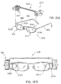
- eyeglasses are shown mounted with a first light module 150 with an integrally formed blinder extension 154 on one temple area of the eyeglasses and a second light module 105 (as generally described above) mounted on the other temple area of the eyeglasses.
- Lighted eyeglasses having the light module 105, mounted in the manner described above may, in certain instances, create glare that is perceivable by the wearer.
- stray or incident light rays 170 that are emitted by the LED 108 may project towards the lens 156 of the pair of eyeglasses 158.
- the rays 170 are then reflected or refracted by the lenses 156 into the eyes of the wearer.
- the glare reducing light module 150 includes an integral projecting portion or blinder extension 154 for reducing potential glare that may be generated as a result of the light 160 emitted by the LED 108 as it is reflected or refracted off the lenses 156 in the glasses 158.
- the light module 150 is comprised of a housing 162 that includes a first cover member 164 and a second cover member 166.
- the second cover member 166 includes the blinder extension 154, which is situated between the LED dome and the lens 156 when the light module is mounted to eyeglasses.
- the blinder extension 154 is configured such that it extends outwards in the direction of the LED 108 and is optimally sized such that the blinder extension 154 blocks the incident rays of light without distracting the wearer or interfering with the light 168 projected for illuminating a reading surface.
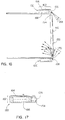
- Figs. 18A, 18B and 19-23 are directed to another clip-on light apparatus 200.
- the apparatus 200 includes a frame 202 which spaces the lights along the length thereof.
- the spacer frame 202 includes opposite ends or end portions 204 and 206 to which the lights 16 are mounted.
- the lights 16 can be provided in the illustrated light modules 150 including the compact housing 162 in which the LED 108 is oriented to project light forwardly so that as depicted in Fig. 9 , the amount of light in the predetermined reading distance range 24 is maximized via large double lit area 140 therein with the frame 202 removably secured to the eyeglasses 208 and the lights turned on.
- retainers 210 are provided at the frame end portions 204 and 206 that are configured to grip the lenses 212 and 214 of the eyeglasses 208.
- the frame 202 can include spacer rods, generally designated 216, that can be shifted along their length relative to each other to allow the frame 202 to adjust to differently sized eyeglasses 208, and specifically for eyeglasses that have different distances between the outer sides 212a and 214a of their respective lenses 212 and 214, at which the retainers 216 preferably grip the lenses 212 and 214, as shown in Fig. 18B .
- the rods 216 are preferably incorporated in a draw spring assembly 218, as best seen in Figs. 19 , 21 and 23 .
- the draw spring assembly 218 includes a coil extension spring 220. In the extended state of the spring 220, the frame end portions 204 and 206 are biased toward each other.
- a user pulls one or both of the end portions 204 and 206 including the associated light modules 150 in a direction away from each other as indicated by double-headed arrow 222 in Figs. 19 and 22 .
- the pulling action compresses the coils 220a of the spring 220 as shown in Fig. 22 so that the frame 202 is spring loaded toward the Fig.
- the aligned retainers 210 shift toward each other to grip onto the lens sides 212a and 214a.
- the retainers 210 are spring loaded into secure gripping engagement with the lenses 212 and 214.
- the retainers 210 at the opposite end portions 210 and 214 are generally spaced at approximately same or slightly greater distance than the distance between the outer lens sides 212a and 214a of the glasses 208 when they are removably attached thereto, as can be seen in Fig. 18B .
- the retainers 210 preferably have a generally U-shaped configuration including forward and rearward legs 224 and 226, respectively.
- the lens sides 212a and 214a fit into the space 228 between the small retainer legs 224 and 226 so that the forward legs 224 extend around the front 212b and 214b of the lenses 212 and 214, and the rearward legs 226 extend around the rear 212c and 214c of the lenses 212 and 214.
- a pair of vertically spaced upper and lower retainer members 210 can be provided at either end portion 204 and 206, as best seen in Fig. 20 .
- the upper and lower retainer members 210 grip the lens sides 212a and 214a along their height so that they are above and below each other.
- pivoting of the apparatus 200 as releasably attached to the eyeglasses 208 such as about a plane defined between a pair of opposite retainers 210 is likewise resisted.
- the retainers 210 are mounted to flange arms 230 at inner end portions 230a thereof.
- the arms 230 are preferably malleable so that the precise position of the retainers 210 can be adjusted for fitting securely against various configurations of lenses 212 and 214, and particularly the outer sides 212a and 214a thereof.
- the arms 230 are formed of thin wire stock that can be slightly bent such as to bring the upper and lower retainers 210 closer together or further apart depending on the height and configuration of the lens sides 212a and 214a.
- the arm end portions 224a can be provided with a U-shaped configuration to form a portion of the retainer members 210 that is integral with the arms 230.
- a small resilient plastic sleeve 232 is fit tightly over the U-shaped arm ends 230a. The sleeve 232 also avoids damaging the eyeglass lenses 212 and 214 with the retainers 210 spring-loaded thereagainst.
- the arms 230 can extend rearwardly from their inner end retainer portions 230a also generally in a U-shaped configuration opening forwardly so that they have an inner leg 234 connected to the retainer portion 230a and an outer leg 236 connected to the light module 150. More specifically, mounting plate 238 is fastened to the housing cover member 166, as shown in Fig. 23 . The outer leg 236 of the mounting arms 230 extends transversely across the plate 238 and is welded or otherwise attached thereto.
- the arms 230 can be formed from a single piece of wire so that there is a vertical wire portion 240 that interconnects the forward ends of the upper and lower outer legs 236 and which can likewise be welded to the plate 238 along the length thereof.
- the frame 202 can be formed of slightly thicker wire stock vis-a-vis that used for the malleable mounting arms 230 so that the frame 202 is of rigid construction.
- the spacer frame 202 includes opposite vertical wire portions 242 and 244 welded or otherwise attached to the mounting plates 238 adjacent to and forwardly of the wire portion 240 that interconnects the retainer arms 230, as previously described.
- the wire portions 242 and 244 project beyond the top side of the modules 150 so that the draw spring assembly 218 is disposed above the eyeglass lenses 212 and 214 when the clip-on light apparatus 200 is releasably secured thereto, as can be seen in Fig. 18B .
- wire portions 242 and 244 are bent above the modules 150 generally at right angles to extend toward each other.
- a horizontal wire portion or rod 246 extends perpendicular from wire portion 242 and through the barrel formed by the coils 220a of the coil spring 220.
- a pair of horizontal wire portions or rods 246 extend perpendicular from wire portion 244 on either side of the spring 220 so that the rod 246 extends between the rods 248.
- the coil spring 220 is disposed between slide members 250 and 252 that ride on respective rods 248 and 246 for adjusting the length of the frame 202.
- the slide member 250 is fixedly connected toward distal end 246a of the rod 246 and the slide member 252 is fixedly connected at the distal ends of the rods 248.
- the slide member 250 extends transversely to span the rods 248 on either side thereof and has a pair of apertures 254 ( Fig. 23 ) sized in clearance fit with the rods 248 so that the slide or plate member 250 can ride therealong.
- the slide or plate member 252 is apertured for riding along the centrally extending rod 246.
- the coil spring 220 normally biases the plate members 250 and 252 apart bringing the frame end portions 204 and 206 toward each other.
- a stop 256 is formed between yoke juncture 258 of the rods 248 and the projecting rod end 246a that extends beyond slide plate 250 fixed thereto to limit the axial expansion of the spring 220, thus defining the closest axial position of the end portions 204 and 206 and opposite light modules 150.
- Adjusting the length of the frame 202 by pulling either or both of the flame end portions 204 and 206 in the axial direction 222 causes the opposite plates 250 and 252 to slide toward each other axially compressing the spring 220 and coils 220a thereof therebetween with rod end 246a a separating from the yoke portion 258, as shown in Fig. 22 .
- the draw spring assembly 218 provides a return force via the compressed spring to bias the retainers 210 at the opposite end portions 204 and 206 back toward each other and into secure engagement with the eyeglasses 208 properly positioned therebetween.
- the adjacent spring coils 220a are engaged without intervening gaps, the maximum length of the frame 202 has been reached thus substantially defining the largest size of eyeglasses 208 as measured between the lenses outer sides 212a and 214a to which the apparatus 200 can be releasably attached or clipped.
- the preferred light modules 150 will be positioned in a manner akin to that as provided on the previously-described lighted eyeglasses 5.
- the retainers 210 are disposed toward the forward end of the housing 162 so that the housing 162 will extend adjacent to and rearwardly along the forward portions of the eyeglass temple arms 260 for the majority of the housing length.
- the forward end of the housing 162 will generally be aligned with the lens front sides 212b and 214b depending on their thickness and degree of curvature.
- the reader will be able to obtain the same benefits as provided by the lighted eyeglasses 5 in terms of having the maximum amount of light trained onto the reading area, while also minimizing glare during reading via the blinder extensions 154 disposed between the LED dome lens 34 projecting out forwardly from the housing 162 and the adjacent eyeglass lenses 212 and 214.
- the apparatus 200 can be easily removed to reduce the weight for maximum comfort when wearing the eyeglasses 208.
- Figs. 24-26 illustrate another alterative clip-on light apparatus 300.
- the apparatus 300 includes an elongate spacer frame 302 having opposite ends 304 and 306 to which the lights 16 are mounted, which again can be provided in the previously-described light modules 150.
- the frame 302 is not adjustable in length and thus can be in the form of a single rod 308 having transverse mounting plates 310 and 312 at either frame end 304 and 306 for fastening of the light modules 150 thereto.
- a clipping mechanism 314 is provided intermediate the frame ends 304 and 306 and preferably centrally therebetween to allow the apparatus 300 to be clipped in the area that is generally disposed between the lenses 212 and 214, this area including inner portions 212a and 214a of the respective lenses and the nose bridge 209 extending therebetween. More particularly, the clipping mechanism 314 has spring-loaded arm pairs 316 and 318 that clamp onto the inner lens portions 212a and 214a or the frame portions thereat to minimize interference with the field of view provided through the lenses 212 and 214.
- An actuator lever 320 is operable to pivot the arm pairs open for securing the apparatus 300 to or removing the apparatus 300 from the eyeglasses 208. With the apparatus 300 releasably clipped onto the eyeglasses 208, the actuator 320 will generally be disposed above the bridge portion 209 of the glasses 208, as can be seen in Fig. 24 .
- the lever 320 is integrally connected with pivotal clamp arms 322 and 324 of the arm pairs 316 and 318 with the other arms 326 and 328 being fixed relative thereto and integrally formed with base 329 of the clipping mechanism 314.
- Torsion springs 330 and 332 are attached between the lever 320 and an upstanding wall portion 329a of base 329 to bias the arms 322 and 324 toward associated arms 326 and 328 for clamping the lens potions 212a and 214a therebetween.
- the lever actuator 320 is pushed against the spring bias provided by springs 330 and 332 to pivot it along with transverse shaft portions 334 and 336 formed integrally between the lever 320 and the arms 322 and 324, respectively, in the direction indicated by arrow 338 in Fig. 26 .
- This pivoting causes pivoting of the integral arms 322 and 324 away from associated arms 326 and 328 in the direction indicated by arrow 340 to separate the ends of the arms 322 and 326 and the arms 324 and 328 from each other allowing the apparatus 300 to be either removed form or secured onto the eyeglasses 208.
- the rod 308 is captured in a recess 342 formed in the base wall portion 329a by ends of the springs 330 and 332. In this manner, the rod 308 can be rotated about its axis 308a to allow a user to direct the light emanating from the modules 150 to their preferences.
- the rod 308 can include enlarged stops formed thereon laterally spaced to be disposed on either side of the base 329 and specifically the wall portion 329a to limit axial or longitudinal shifting of the rod 308 relative to the clipping mechanism 314.
Landscapes
- Engineering & Computer Science (AREA)
- General Engineering & Computer Science (AREA)
- Physics & Mathematics (AREA)
- Health & Medical Sciences (AREA)
- General Physics & Mathematics (AREA)
- Ophthalmology & Optometry (AREA)
- Optics & Photonics (AREA)
- Eyeglasses (AREA)
- Arrangement Of Elements, Cooling, Sealing, Or The Like Of Lighting Devices (AREA)
- Eye Examination Apparatus (AREA)
- Helmets And Other Head Coverings (AREA)
- Illuminated Signs And Luminous Advertising (AREA)
- Image Input (AREA)
- Lenses (AREA)
- Facsimile Scanning Arrangements (AREA)
- Optical Head (AREA)
Applications Claiming Priority (3)
| Application Number | Priority Date | Filing Date | Title |
|---|---|---|---|
| US10/006,919 US6612695B2 (en) | 2001-11-07 | 2001-11-07 | Lighted reading glasses |
| US10/145,595 US6612696B2 (en) | 2001-11-07 | 2002-05-14 | Lighted reading glasses |
| EP02778755A EP1451633B1 (fr) | 2001-11-07 | 2002-11-07 | Lunettes de lecture eclairantes |
Related Parent Applications (2)
| Application Number | Title | Priority Date | Filing Date |
|---|---|---|---|
| EP02778755.5 Division | 2002-11-07 | ||
| EP02778755A Division EP1451633B1 (fr) | 2001-11-07 | 2002-11-07 | Lunettes de lecture eclairantes |
Publications (2)
| Publication Number | Publication Date |
|---|---|
| EP2290433A1 true EP2290433A1 (fr) | 2011-03-02 |
| EP2290433B1 EP2290433B1 (fr) | 2016-04-06 |
Family
ID=21723270
Family Applications (3)
| Application Number | Title | Priority Date | Filing Date |
|---|---|---|---|
| EP02778755A Expired - Lifetime EP1451633B1 (fr) | 2001-11-07 | 2002-11-07 | Lunettes de lecture eclairantes |
| EP10181592A Withdrawn EP2299311A1 (fr) | 2001-11-07 | 2002-11-07 | Module d'éclairage pour lunettes de lecture éclairées |
| EP10181593.4A Expired - Lifetime EP2290433B1 (fr) | 2001-11-07 | 2002-11-07 | Lunettes de lecture eclairantes |
Family Applications Before (2)
| Application Number | Title | Priority Date | Filing Date |
|---|---|---|---|
| EP02778755A Expired - Lifetime EP1451633B1 (fr) | 2001-11-07 | 2002-11-07 | Lunettes de lecture eclairantes |
| EP10181592A Withdrawn EP2299311A1 (fr) | 2001-11-07 | 2002-11-07 | Module d'éclairage pour lunettes de lecture éclairées |
Country Status (8)
| Country | Link |
|---|---|
| US (7) | US6612695B2 (fr) |
| EP (3) | EP1451633B1 (fr) |
| AT (1) | ATE544088T1 (fr) |
| AU (1) | AU2002340396A1 (fr) |
| CA (3) | CA2855470C (fr) |
| ES (1) | ES2583685T3 (fr) |
| WO (1) | WO2003040808A2 (fr) |
| ZA (1) | ZA200403826B (fr) |
Cited By (24)
| Publication number | Priority date | Publication date | Assignee | Title |
|---|---|---|---|---|
| US8152330B2 (en) | 2001-11-07 | 2012-04-10 | Michael Waters | Lighted reading glasses |
| US8235524B2 (en) | 2001-11-07 | 2012-08-07 | Michael Waters | Illuminated eyewear |
| US8388164B2 (en) | 2005-05-17 | 2013-03-05 | Michael Waters | Hands-Free lighting devices |
| USD682343S1 (en) | 2011-12-23 | 2013-05-14 | Michael Waters | Lighted glasses |
| US8444266B2 (en) | 2009-09-30 | 2013-05-21 | Michael Waters | Illuminated eyewear |
| US8485682B2 (en) | 2007-10-29 | 2013-07-16 | Waters Industries, Inc. | Illuminated eyeglass assembly |
| US8491118B2 (en) | 2001-11-07 | 2013-07-23 | Michael Waters | Lighted reading glasses |
| US8540364B2 (en) | 2010-09-14 | 2013-09-24 | Michael Waters | Lighted glasses |
| US8545012B2 (en) | 2005-05-17 | 2013-10-01 | Michael Waters | Illuminated eyewear |
| US8979295B2 (en) | 2005-05-17 | 2015-03-17 | Michael Waters | Rechargeable lighted glasses |
| USD770143S1 (en) | 2014-05-23 | 2016-11-01 | Michael Waters | Beanie with means for illumination |
| US9526292B2 (en) | 2005-05-17 | 2016-12-27 | Michael Waters | Power modules and headgear |
| US9526287B2 (en) | 2011-12-23 | 2016-12-27 | Michael Waters | Lighted hat |
| US9568173B2 (en) | 2011-12-23 | 2017-02-14 | Michael Waters | Lighted hat |
| US9585431B2 (en) | 2007-12-18 | 2017-03-07 | Waters Industries, Inc. | Lighted hat |
| US9609902B2 (en) | 2011-12-23 | 2017-04-04 | Michael Waters | Headgear having a camera device |
| US9717633B2 (en) | 2013-03-15 | 2017-08-01 | Michael Waters | Lighted headgear |
| US9872530B2 (en) | 2010-04-30 | 2018-01-23 | Michael Waters | Lighted headgear and accessories therefor |
| USD824557S1 (en) | 2014-12-02 | 2018-07-31 | Michael Waters | Flashlight |
| US10069318B2 (en) | 2014-12-02 | 2018-09-04 | Michael Waters | LED flashlight with longitudinal cooling fins |
| US10159294B2 (en) | 2012-12-19 | 2018-12-25 | Michael Waters | Lighted solar hat |
| US10791783B1 (en) | 2019-05-16 | 2020-10-06 | Waters Industries, Inc. | Lighted headgear and accessories therefor |
| RU220676U1 (ru) * | 2023-03-07 | 2023-09-28 | Ангелина Викторовна Деева | Бестеневой светодиодный осветитель |
| US12171293B2 (en) | 2021-12-27 | 2024-12-24 | Waters Industries, Inc. | Lighted headgear and accessories therefor |
Families Citing this family (176)
| Publication number | Priority date | Publication date | Assignee | Title |
|---|---|---|---|---|
| US20060215393A1 (en) * | 2003-06-25 | 2006-09-28 | Vanderschuit Carl R | Lighted hats |
| US7052154B2 (en) * | 2003-06-25 | 2006-05-30 | Vanderschuit Carl R | Lighted hat |
| US7452092B2 (en) * | 2003-06-25 | 2008-11-18 | Vanderschuit Carl R | Illuminated implements for drinking and/or eating and related methods |
| DE10029489A1 (de) * | 2000-06-15 | 2002-03-28 | Tesa Ag | Oberflächenschutzfolie für Lackoberflächen mit einer Selbstklebemasse auf Polyurethan-Basis |
| US6837590B2 (en) * | 2000-09-27 | 2005-01-04 | Jezign, Llc | Illuminated cap and shoe set |
| US6733150B1 (en) * | 2001-04-20 | 2004-05-11 | Edward B. Hanley | Headgear with forward illumination |
| US7234831B1 (en) | 2001-04-20 | 2007-06-26 | Hanley Edward B | Headgear with forward illumination |
| USD554848S1 (en) | 2001-09-27 | 2007-11-13 | Jezign, Llc | Illuminated shoe lower |
| US6612695B2 (en) * | 2001-11-07 | 2003-09-02 | Michael Waters | Lighted reading glasses |
| US6994445B1 (en) * | 2002-09-04 | 2006-02-07 | Pomes Nick J | Cap with underside light |
| US7427149B2 (en) * | 2003-01-22 | 2008-09-23 | Dae Up Sohn | Clip type light detachably coupled with cap |
| KR200312151Y1 (ko) * | 2003-01-22 | 2003-05-09 | 주식회사 나스켐 | 클립형 발광기 |
| US6824265B1 (en) | 2003-03-31 | 2004-11-30 | Wesley Stephen Harper | Illuminated safety and work glasses |
| US7500746B1 (en) | 2004-04-15 | 2009-03-10 | Ip Venture, Inc. | Eyewear with radiation detection system |
| US7922321B2 (en) | 2003-10-09 | 2011-04-12 | Ipventure, Inc. | Eyewear supporting after-market electrical components |
| US8109629B2 (en) | 2003-10-09 | 2012-02-07 | Ipventure, Inc. | Eyewear supporting electrical components and apparatus therefor |
| US7000841B2 (en) * | 2003-05-16 | 2006-02-21 | Angel Lighting Llc | Lighting apparatus for mounting on hat brim |
| US10252079B2 (en) | 2003-06-06 | 2019-04-09 | Koninklijke Philips N.V. | Hand-held light therapy apparatus |
| CN102247031A (zh) * | 2003-06-25 | 2011-11-23 | 卡尔·R·范德舒伊特 | 发光帽 |
| US6935761B2 (en) * | 2003-06-25 | 2005-08-30 | Carl R. Vanderschuit | Lighted hat |
| FI117487B (fi) * | 2003-07-11 | 2006-10-31 | Matti Lahtinen | Henkilökohtainen LED-valaisin |
| US11513371B2 (en) | 2003-10-09 | 2022-11-29 | Ingeniospec, Llc | Eyewear with printed circuit board supporting messages |
| US11630331B2 (en) | 2003-10-09 | 2023-04-18 | Ingeniospec, Llc | Eyewear with touch-sensitive input surface |
| US6969178B2 (en) * | 2003-10-14 | 2005-11-29 | Steven Zuloff | Portable black light device |
| GB2411009A (en) * | 2004-02-13 | 2005-08-17 | Patonlite Spectacles Ltd | Eyewear with one or more light emitting diodes |
| FI20041072L (fi) * | 2004-04-05 | 2005-10-06 | Ralf Karlsson | Valaisimella varustettu käyttöesine |
| US7111956B2 (en) * | 2004-04-05 | 2006-09-26 | Light-On, Llc | Apparatuses and methods for vision assistance |
| US20050248932A1 (en) * | 2004-05-07 | 2005-11-10 | Michael Waters | Clip-on light apparatus |
| US11644693B2 (en) | 2004-07-28 | 2023-05-09 | Ingeniospec, Llc | Wearable audio system supporting enhanced hearing support |
| US11829518B1 (en) | 2004-07-28 | 2023-11-28 | Ingeniospec, Llc | Head-worn device with connection region |
| US11852901B2 (en) | 2004-10-12 | 2023-12-26 | Ingeniospec, Llc | Wireless headset supporting messages and hearing enhancement |
| US20080263752A1 (en) * | 2004-12-17 | 2008-10-30 | Insight Technology, Inc. | Method and Apparatus for Mounting a Vision System |
| WO2006069144A2 (fr) * | 2004-12-21 | 2006-06-29 | University Of Pittsburgh - Of The Commonwealth System Of Higher Education | Appareil de stimulation cerebrale profonde, et procedes associes |
| US20060198122A1 (en) * | 2005-03-04 | 2006-09-07 | R2 Innovation Llc | Illuminated headwear |
| NL1029496C1 (nl) * | 2005-07-12 | 2007-01-15 | Adrianus Speekenbrink | Brilmontuur met voorzieningen voor het verlichten van objecten. |
| WO2007024818A2 (fr) * | 2005-08-24 | 2007-03-01 | Michael Maurice Fjelstad | Lunettes equipees de branches flexibles lestees |
| US20120176580A1 (en) * | 2005-10-11 | 2012-07-12 | Vanderbilt University | Electronics assembly in low-vision reader |
| US7942522B2 (en) * | 2005-09-29 | 2011-05-17 | Vanderbilt University | Illuminated low-vision spectacles |
| US12044901B2 (en) | 2005-10-11 | 2024-07-23 | Ingeniospec, Llc | System for charging embedded battery in wireless head-worn personal electronic apparatus |
| US12535698B2 (en) | 2005-10-11 | 2026-01-27 | Ingeniospec, Llc | Head-worn structure with fitness monitoring |
| US11733549B2 (en) | 2005-10-11 | 2023-08-22 | Ingeniospec, Llc | Eyewear having removable temples that support electrical components |
| US20070081122A1 (en) * | 2005-10-12 | 2007-04-12 | Chih-Hung Huang | Structure of an eyeglasses lamp |
| US7287882B2 (en) * | 2005-10-19 | 2007-10-30 | Jaeyou Co., Ltd. | Shining lock structure |
| NZ552414A (en) | 2005-12-22 | 2008-04-30 | Simon Dyer | Lighting apparatus in the visor of a hat |
| US7513674B1 (en) * | 2006-01-20 | 2009-04-07 | Kevin Gerard Donahue | See-through one-way light-emitting light guide |
| US20090105782A1 (en) * | 2006-03-15 | 2009-04-23 | University Of Pittsburgh-Of The Commonwealth System Of Higher Education | Vagus nerve stimulation apparatus, and associated methods |
| US7207896B1 (en) * | 2006-03-27 | 2007-04-24 | Sudol Mark S | Aid for training a golf swing |
| WO2008011750A1 (fr) * | 2006-06-26 | 2008-01-31 | Qingjiang Wang | Casquette à fonction d'éclairage |
| USD556429S1 (en) * | 2006-08-04 | 2007-12-04 | Irina Saveliev | Hat brim |
| US20080068824A1 (en) * | 2006-09-20 | 2008-03-20 | Ching-Hsiang Wang | Eyeglasses with lighting device |
| US20080080172A1 (en) * | 2006-09-29 | 2008-04-03 | Bo Mayo | Hunting apparel with indicator lights |
| US7465078B2 (en) * | 2006-11-01 | 2008-12-16 | General Scientific Corporation | Heat-dissipating head-mounted LED lamp |
| CA2618594A1 (fr) * | 2007-01-10 | 2008-07-10 | Robert Bryant | Module a diode(s) electroluminescente(s) |
| US7621000B1 (en) | 2007-04-10 | 2009-11-24 | Fulton Brian K | Headgear for attaching a toy |
| US7866066B2 (en) | 2007-04-13 | 2011-01-11 | Forbes Brandon F | Footwear device with scrolling light emitting diode display |
| US20080266839A1 (en) * | 2007-04-25 | 2008-10-30 | Claypool Thomas A | Headwear and headwear bill with integrated light assembly |
| US8390216B2 (en) * | 2007-06-12 | 2013-03-05 | Video Refurbishing Services, Inc. | Apparatus and method for a light-emitting diode lamp that simulates a filament lamp |
| US7854668B2 (en) * | 2007-08-10 | 2010-12-21 | Lance Shelton | Laser ball shooting aid |
| WO2009025472A1 (fr) * | 2007-08-20 | 2009-02-26 | E-Gun Technulogy Co., Ltd | Lunettes à fonction éclairante |
| KR100904764B1 (ko) * | 2007-08-20 | 2009-06-29 | 이건테크놀로지 주식회사 | 조명 기능을 갖는 안경 |
| USD627140S1 (en) | 2007-11-14 | 2010-11-16 | Simon Dyer | Combined visor and lights |
| US8757831B2 (en) | 2007-12-18 | 2014-06-24 | Michael Waters | Headgear having an electrical device and power source mounted thereto |
| WO2009079656A2 (fr) | 2007-12-18 | 2009-06-25 | Michael Waters | Dispositifs d'éclairage mains libres |
| US8491145B2 (en) | 2007-12-18 | 2013-07-23 | Waters Industries, Inc. | Illuminated headgear having switch devices and packaging therefor |
| KR101024191B1 (ko) * | 2008-01-24 | 2011-03-22 | 손대업 | 모자부착형 조명장치 |
| US7607775B2 (en) * | 2008-02-26 | 2009-10-27 | Mr. Christmas Incorporated | Illuminating eyeglasses and eyeglasses frame structure |
| USD605218S1 (en) * | 2008-02-26 | 2009-12-01 | Mr. Christmas Incorporated | Temple pieces for illuminating eyeglasses |
| USD611086S1 (en) * | 2008-02-26 | 2010-03-02 | Mr. Christmas Incorporated | Illuminating eyeglasses |
| US7611241B2 (en) * | 2008-03-13 | 2009-11-03 | Hsin Chen | Spectacle with an illumination device |
| US20100050689A1 (en) * | 2008-08-27 | 2010-03-04 | Marni Markell Hurwitz | Decorative pendant or locket housing a reading lens |
| USD597691S1 (en) * | 2008-10-31 | 2009-08-04 | Oscar Fuentes | Head light for use with a helmet |
| US8161570B2 (en) * | 2008-12-05 | 2012-04-24 | Sign Brite Inc. | Catching gear with apparatus for increasing hand signal visibility |
| EP2440845B1 (fr) | 2009-06-09 | 2021-01-06 | Kerr Corporation | Ensemble d'éclairage pouvant être porté par l'utilisateur |
| US20100313334A1 (en) * | 2009-06-11 | 2010-12-16 | Bobblesigns.Com Llc | Hat with Electronic Display |
| USD621138S1 (en) * | 2009-07-02 | 2010-08-10 | Christian Roos | Illuminated visor |
| CN201489222U (zh) * | 2009-09-07 | 2010-05-26 | 张德胜 | 触摸式照明功能眼镜 |
| USD629182S1 (en) * | 2009-07-29 | 2010-12-21 | Maurice Castiel | Cap having lights |
| US8210676B1 (en) | 2009-09-21 | 2012-07-03 | Marvin James Hunt | Sportsman's reading glasses |
| USD617826S1 (en) * | 2010-01-14 | 2010-06-15 | Michael Waters | Lighted eyeglasses |
| US8550649B2 (en) * | 2010-02-15 | 2013-10-08 | Webb T. Nelson | Stereoscopic illumination system for retroreflective materials |
| US8746914B2 (en) | 2010-02-15 | 2014-06-10 | Webb T. Nelson | Sports set that utilize stereoscopic illumination and retroreflective materials |
| US9223134B2 (en) | 2010-02-28 | 2015-12-29 | Microsoft Technology Licensing, Llc | Optical imperfections in a light transmissive illumination system for see-through near-eye display glasses |
| WO2011106797A1 (fr) | 2010-02-28 | 2011-09-01 | Osterhout Group, Inc. | Déclenchement de projection par un repère externe dans des lunettes intégrales |
| US9182596B2 (en) | 2010-02-28 | 2015-11-10 | Microsoft Technology Licensing, Llc | See-through near-eye display glasses with the optical assembly including absorptive polarizers or anti-reflective coatings to reduce stray light |
| US8482859B2 (en) | 2010-02-28 | 2013-07-09 | Osterhout Group, Inc. | See-through near-eye display glasses wherein image light is transmitted to and reflected from an optically flat film |
| US8472120B2 (en) | 2010-02-28 | 2013-06-25 | Osterhout Group, Inc. | See-through near-eye display glasses with a small scale image source |
| US9759917B2 (en) | 2010-02-28 | 2017-09-12 | Microsoft Technology Licensing, Llc | AR glasses with event and sensor triggered AR eyepiece interface to external devices |
| US8467133B2 (en) | 2010-02-28 | 2013-06-18 | Osterhout Group, Inc. | See-through display with an optical assembly including a wedge-shaped illumination system |
| US8488246B2 (en) | 2010-02-28 | 2013-07-16 | Osterhout Group, Inc. | See-through near-eye display glasses including a curved polarizing film in the image source, a partially reflective, partially transmitting optical element and an optically flat film |
| US20150309316A1 (en) | 2011-04-06 | 2015-10-29 | Microsoft Technology Licensing, Llc | Ar glasses with predictive control of external device based on event input |
| US9366862B2 (en) | 2010-02-28 | 2016-06-14 | Microsoft Technology Licensing, Llc | System and method for delivering content to a group of see-through near eye display eyepieces |
| US9097891B2 (en) | 2010-02-28 | 2015-08-04 | Microsoft Technology Licensing, Llc | See-through near-eye display glasses including an auto-brightness control for the display brightness based on the brightness in the environment |
| US8477425B2 (en) | 2010-02-28 | 2013-07-02 | Osterhout Group, Inc. | See-through near-eye display glasses including a partially reflective, partially transmitting optical element |
| US10180572B2 (en) | 2010-02-28 | 2019-01-15 | Microsoft Technology Licensing, Llc | AR glasses with event and user action control of external applications |
| US9229227B2 (en) | 2010-02-28 | 2016-01-05 | Microsoft Technology Licensing, Llc | See-through near-eye display glasses with a light transmissive wedge shaped illumination system |
| US9341843B2 (en) | 2010-02-28 | 2016-05-17 | Microsoft Technology Licensing, Llc | See-through near-eye display glasses with a small scale image source |
| US9129295B2 (en) | 2010-02-28 | 2015-09-08 | Microsoft Technology Licensing, Llc | See-through near-eye display glasses with a fast response photochromic film system for quick transition from dark to clear |
| US20120249797A1 (en) | 2010-02-28 | 2012-10-04 | Osterhout Group, Inc. | Head-worn adaptive display |
| US9091851B2 (en) | 2010-02-28 | 2015-07-28 | Microsoft Technology Licensing, Llc | Light control in head mounted displays |
| US9134534B2 (en) | 2010-02-28 | 2015-09-15 | Microsoft Technology Licensing, Llc | See-through near-eye display glasses including a modular image source |
| US9128281B2 (en) | 2010-09-14 | 2015-09-08 | Microsoft Technology Licensing, Llc | Eyepiece with uniformly illuminated reflective display |
| US9285589B2 (en) | 2010-02-28 | 2016-03-15 | Microsoft Technology Licensing, Llc | AR glasses with event and sensor triggered control of AR eyepiece applications |
| US9097890B2 (en) | 2010-02-28 | 2015-08-04 | Microsoft Technology Licensing, Llc | Grating in a light transmissive illumination system for see-through near-eye display glasses |
| USD628617S1 (en) * | 2010-03-01 | 2010-12-07 | Michael Waters | Lighted glasses |
| US20120033410A1 (en) * | 2010-07-23 | 2012-02-09 | Gregory Garman | Floatation device for glasses |
| USD649669S1 (en) * | 2010-10-01 | 2011-11-29 | Malecki S Douglas | Headgear having safety illumination |
| USD636009S1 (en) | 2010-10-15 | 2011-04-12 | Marvin James Hunt | Clip on monocles |
| USD661470S1 (en) * | 2010-12-15 | 2012-06-12 | Joanne Baron | Brim with light attachment |
| US8188880B1 (en) * | 2011-03-14 | 2012-05-29 | Google Inc. | Methods and devices for augmenting a field of view |
| US8919984B1 (en) | 2011-04-04 | 2014-12-30 | Outdoor Cap Co., Inc. | Multiple light source cap device with short and long range lighting |
| US9033534B2 (en) | 2011-04-20 | 2015-05-19 | Jasper Ridge Inc. | Hands-free vision aid |
| US8813268B1 (en) | 2011-09-05 | 2014-08-26 | Outdoor Cap Company, Inc. | Lighted headwear with recessed light source and lens |
| JP2013096020A (ja) * | 2011-10-28 | 2013-05-20 | Sumita Optical Glass Inc | ヘルメット |
| DK2590008T3 (en) * | 2011-11-03 | 2016-06-27 | Fortuna Urbis S R L | Glasses |
| CA2794370A1 (fr) | 2011-11-04 | 2013-05-04 | Michael Waters | Chapeau a fonction de desactivation automatique pour dispositifs electriques |
| US9167860B2 (en) | 2012-01-13 | 2015-10-27 | Craig M. Fedewa | Protective modular helmet with integrated lighting system |
| USD660902S1 (en) | 2012-02-02 | 2012-05-29 | Hasbro, Inc. | Vision apparatus |
| US8837788B2 (en) | 2012-06-04 | 2014-09-16 | J. Stephen Hudgins | Disruption of facial recognition system |
| US9622529B2 (en) * | 2012-07-18 | 2017-04-18 | Wilcox Industries Corp. | Helmet edge trim wiring harness |
| US20140053318A1 (en) | 2012-08-02 | 2014-02-27 | Nrg Products, Llc | Power headgear |
| FR2995491A1 (fr) * | 2012-09-11 | 2014-03-14 | Zedel | Lampe electrique portative dotee d'un dispositif de regulation automatique de l'eclairage |
| WO2014122677A1 (fr) | 2013-02-06 | 2014-08-14 | Getitaly S.R.L. | Lunettes avec éclairage et système de charge photovoltaïque |
| US20140301595A1 (en) * | 2013-04-09 | 2014-10-09 | Corey LaMont EGLESTON | Apparel with speaker assembly |
| USD755281S1 (en) | 2013-06-07 | 2016-05-03 | Mitsui Chemicals, Inc. | Adapter for eyewear |
| US9629435B2 (en) * | 2013-06-26 | 2017-04-25 | Antonio Anderson | Combination hair wrap, sleep mask, and reading light |
| USD745084S1 (en) | 2013-07-18 | 2015-12-08 | Mitsui Chemicals, Inc. | Adapter for eyewear |
| KR102174752B1 (ko) | 2014-08-26 | 2020-11-05 | 삼성전자주식회사 | 회전장치 및 이를 포함하는 전자장치 |
| WO2017092054A1 (fr) * | 2015-12-04 | 2017-06-08 | 林鹤 | Interrupteur magnétique et lunettes avec lampe |
| US10031345B2 (en) * | 2015-12-15 | 2018-07-24 | LooLoops, LLC | Slip-resistant eyewear system |
| WO2017106385A2 (fr) | 2015-12-15 | 2017-06-22 | LooLoops, LLC | Système de lunettes antidérapantes |
| US10444534B2 (en) | 2016-09-12 | 2019-10-15 | LooLoopsLLC | Slip-resistant eyewear system |
| US20180146734A1 (en) * | 2016-11-30 | 2018-05-31 | Caitlin Kelly | Modular hats and headwear |
| US10960224B2 (en) | 2017-01-12 | 2021-03-30 | Janssen Pharmaceutica Nv | Trans-orbital infrared light therapy |
| CN107065229B (zh) * | 2017-05-06 | 2019-03-29 | 深圳市晓控通信科技有限公司 | 一种具有照明功能的智能眼镜 |
| CN107493642B (zh) * | 2017-08-24 | 2020-06-30 | 深圳大学 | 优化阅读时的视觉舒适度的光环境调节方法及系统 |
| US11002437B2 (en) | 2017-12-07 | 2021-05-11 | First-Light Usa, Llc | Head-mounted illumination devices |
| US11144125B2 (en) | 2017-12-07 | 2021-10-12 | First-Light Usa, Llc | Hands-free switch system |
| US10777048B2 (en) | 2018-04-12 | 2020-09-15 | Ipventure, Inc. | Methods and apparatus regarding electronic eyewear applicable for seniors |
| US11473761B2 (en) | 2018-06-21 | 2022-10-18 | Biolite Inc. | Headlamp integrated into a flexible composite headband |
| US10768451B1 (en) | 2018-06-26 | 2020-09-08 | Snap Inc. | Diffusers in wearable devices |
| USD900209S1 (en) | 2018-08-22 | 2020-10-27 | Alessandra Marzano | Charm for eyeglasses |
| US10751637B1 (en) * | 2018-10-15 | 2020-08-25 | Lightuptoys.Com Llc | Wearable and illuminating wings |
| US10926102B2 (en) | 2019-04-15 | 2021-02-23 | Janssen Pharmaceutica Nv | Transorbital NIR LIGHT THERAPY DEVICES |
| US10874874B2 (en) | 2019-04-15 | 2020-12-29 | Janssen Pharmaceutica Nv | Transorbital NIR light therapy device |
| US11071497B2 (en) * | 2019-06-11 | 2021-07-27 | Gentex Corporation | Wearable medical device |
| USD917608S1 (en) | 2019-06-18 | 2021-04-27 | V.P. Gabriel, Inc. | Visor device attachment |
| US11553313B2 (en) | 2020-07-02 | 2023-01-10 | Hourglass Medical Llc | Clench activated switch system |
| US12380798B2 (en) | 2020-07-02 | 2025-08-05 | Hourglass Medical Llc | Switch system for operating a controlled device |
| US11698678B2 (en) | 2021-02-12 | 2023-07-11 | Hourglass Medical Llc | Clench-control accessory for head-worn devices |
| USD1039595S1 (en) | 2021-03-22 | 2024-08-20 | Pair Eyewear, Inc. | Glasses frames |
| USD1016126S1 (en) | 2021-03-22 | 2024-02-27 | Pair Eyewear, Inc. | Glasses frames |
| WO2022225912A1 (fr) | 2021-04-21 | 2022-10-27 | Hourglass Medical Llc | Procédés pour des systèmes commandés par un mouvement musculaire de suppression de la voix |
| CN115702847A (zh) * | 2021-08-11 | 2023-02-17 | 林伯刚 | 穿戴式装置及其使用方法 |
| US11409135B1 (en) | 2021-10-27 | 2022-08-09 | Pair Eyewear, Inc. | Eyeglass with removably attachable top |
| US12367793B1 (en) | 2021-12-22 | 2025-07-22 | Apple Inc. | Electronic devices with edge illuminators |
| US12075873B2 (en) | 2022-01-21 | 2024-09-03 | Carhartt, Inc. | Ilumination assembly for a hat |
| USD1079086S1 (en) | 2022-03-02 | 2025-06-10 | Carhartt, Inc. | Light assembly |
| EP4310389A1 (fr) * | 2022-07-21 | 2024-01-24 | Techtronic Cordless GP | Lampe frontale |
| EP4591113A4 (fr) | 2022-10-04 | 2026-04-01 | Hourglass Medical Llc | Commutateur de pont de lunettes |
| US12443056B2 (en) | 2022-12-22 | 2025-10-14 | Luminyx Llc | Eyewear with circumambient illumination |
| DE102024109492A1 (de) | 2023-04-07 | 2024-10-10 | Milwaukee Electric Tool Corporation | Tragbare nackenleuchte |
| USD1032708S1 (en) | 2023-06-08 | 2024-06-25 | Pair Eyewear, Inc. | Eyewear frame |
| USD1017676S1 (en) | 2023-06-08 | 2024-03-12 | Pair Eyewear, Inc. | Eyewear front frame |
| USD1032709S1 (en) | 2023-06-08 | 2024-06-25 | Pair Eyewear, Inc. | Eyewear frame |
| USD1017674S1 (en) | 2023-06-08 | 2024-03-12 | Pair Eyewear, Inc. | Eyewear front frame |
| USD1017675S1 (en) | 2023-06-08 | 2024-03-12 | Pair Eyewear, Inc. | Eyewear front frame |
| USD1020845S1 (en) | 2023-06-08 | 2024-04-02 | Pair Eyewear, Inc. | Eyewear front frame |
| USD1017677S1 (en) | 2023-06-08 | 2024-03-12 | Pair Eyewear, Inc. | Eyewear front frame |
| USD1022013S1 (en) | 2023-06-09 | 2024-04-09 | Pair Eyewear, Inc. | Eyewear frame |
| US12540721B2 (en) | 2024-05-01 | 2026-02-03 | Luminyx Llc | Modular, universal, and standalone eyewear circumambient illumination kits and systems |
| USD1121012S1 (en) | 2024-08-27 | 2026-03-31 | Pair Eyewear, Inc. | Eyewear front frame |
| USD1123023S1 (en) | 2024-08-27 | 2026-04-21 | Pair Eyewear, Inc. | Eyewear |
| USD1124113S1 (en) | 2024-08-27 | 2026-04-28 | Pair Eyewear, Inc. | Eyewear |
| USD1123026S1 (en) | 2024-08-27 | 2026-04-21 | Pair Eyewear, Inc. | Eyewear |
| USD1120090S1 (en) | 2024-08-27 | 2026-03-24 | Pair Eyewear, Inc. | Eyewear front frame |
| USD1123024S1 (en) | 2024-08-27 | 2026-04-21 | Pair Eyewear, Inc. | Eyewear front frame |
Citations (4)
| Publication number | Priority date | Publication date | Assignee | Title |
|---|---|---|---|---|
| US4959760A (en) * | 1990-01-19 | 1990-09-25 | Te Sheng Wu | Lighting equipment for an eyeglasses |
| DE9410886U1 (de) * | 1994-07-07 | 1994-09-15 | Wu, Der-Shan, Sertou Hsian, Changhua | Tragbares Mini-Beleuchtungsgerät |
| US6056413A (en) * | 1997-12-29 | 2000-05-02 | Urso; Charles L. | Cap lamp |
| WO2001077575A1 (fr) * | 2000-04-05 | 2001-10-18 | Allen David M | Dispositif d'eclairage portable |
Family Cites Families (124)
| Publication number | Priority date | Publication date | Assignee | Title |
|---|---|---|---|---|
| US3123208A (en) | 1964-03-03 | Packaging and display device and method for | ||
| US1572210A (en) * | 1926-02-09 | Combined visor and automatic flash light | ||
| US1255265A (en) | 1916-04-12 | 1918-02-05 | Ladislaus Zachara | Electric spectacle lamp and frame. |
| US1261824A (en) * | 1917-04-04 | 1918-04-09 | Henry La Vine | Portable electric light. |
| US1448353A (en) | 1921-12-21 | 1923-03-13 | Franco Electric Corp | Flash light |
| US1615067A (en) * | 1926-04-15 | 1927-01-18 | Boerman Jacob | Inspection light |
| US2531585A (en) * | 1947-08-04 | 1950-11-28 | William H Pope | Combination flashlight, eyepiece, and headgear |
| US2591112A (en) | 1948-04-27 | 1952-04-01 | Henry Hyman | Vest pocket flashlight, including electric system and lock subassembly |
| US2638532A (en) | 1949-03-23 | 1953-05-12 | Thomas L Brady | Combined spectacle frame and light |
| US2567046A (en) | 1950-06-09 | 1951-09-04 | Stewart R Brown Mfg Co Inc | Two-color wand light attachment for flashlights |
| US2904670A (en) | 1957-04-12 | 1959-09-15 | Calmes Andre | Illuminating spectacles |
| US3032647A (en) | 1959-01-22 | 1962-05-01 | Wansky Morris Harold | Cap or hat light |
| US3060308A (en) | 1959-05-08 | 1962-10-23 | Anton J Fortuna | Illuminated optical device |
| US2966580A (en) | 1959-09-24 | 1960-12-27 | Frank E Taylor | Battery hand lamp |
| US3040881A (en) | 1960-11-09 | 1962-06-26 | Bachmann Bros Inc | Display for eyeglasses |
| US3184058A (en) | 1963-10-24 | 1965-05-18 | Bachmann Bros Inc | Spectacle sales display |
| US3350552A (en) | 1965-03-05 | 1967-10-31 | Paul A Lawrence | Illuminating device for a person's head |
| US3634676A (en) * | 1970-03-23 | 1972-01-11 | Angelo Castellano | Combined spectacle frame and light |
| US3769663A (en) * | 1972-05-04 | 1973-11-06 | T Perl | Flashlight attachment clip for spectacles |
| US4005776A (en) | 1975-05-02 | 1977-02-01 | Plastofilm Industries, Inc. | Package for oral thermometer, catheter or the like |
| US4283127A (en) | 1979-11-29 | 1981-08-11 | Marvin Glass & Associates | Novelty eyeglasses |
| US4332007A (en) | 1980-10-06 | 1982-05-25 | Jedco Products Limited, Inc. | Utility light |
| DE3043007A1 (de) * | 1980-11-11 | 1982-06-16 | Charles Dr.med. Paris Freche | Optische einrichtung mit beleuchtung |
| DE3426358A1 (de) * | 1984-07-17 | 1986-01-23 | Patent-Treuhand-Gesellschaft für elektrische Glühlampen mbH, 8000 München | Tragbare leuchtvorrichtung |
| US4669610A (en) | 1986-01-13 | 1987-06-02 | Conair Corporation | Package assembly |
| US4774643A (en) * | 1986-11-17 | 1988-09-27 | Diagin, Inc. | Illuminator for radiation dosimeter and method of manufacture |
| JP2685770B2 (ja) * | 1987-12-28 | 1997-12-03 | 株式会社東芝 | 不揮発性半導体記憶装置 |
| USD316932S (en) | 1988-01-19 | 1991-05-21 | Escher Jr William F | Floatable eyeglass case, or similar article |
| US5060814A (en) | 1990-10-22 | 1991-10-29 | Abbott Laboratories | Molded plastic container for packaging multiple product samples |
| US5164749A (en) * | 1990-12-10 | 1992-11-17 | Opsales/Lenservice, Inc. | Clip for mounting sunglass lenses on spectacles |
| US5174649B1 (en) * | 1991-07-17 | 1998-04-14 | Precision Solar Controls Inc | Led lamp including refractive lens element |
| US5158356A (en) * | 1992-02-10 | 1992-10-27 | Guthrie Alan V | Ornamental lamp with internal switch |
| US5249675A (en) | 1992-02-21 | 1993-10-05 | Kurt Strauss | Packaging for eyewear |
| US5183326A (en) * | 1992-02-25 | 1993-02-02 | Rcp Enterprises, Inc. | Underwater flashlight holder |
| US5218385A (en) | 1992-03-17 | 1993-06-08 | Lii Jein Hei | Flash light eyeglasses with hinge switch |
| USD343470S (en) | 1992-04-07 | 1994-01-18 | John Manufacturing Limited | Double torch |
| US5958358A (en) * | 1992-07-08 | 1999-09-28 | Yeda Research And Development Co., Ltd. | Oriented polycrystalline thin films of transition metal chalcogenides |
| USD349123S (en) | 1992-07-31 | 1994-07-26 | Luxtec Corporation | Spectacles having integral illumination |
| US5331357A (en) | 1992-07-31 | 1994-07-19 | Luxtec Corporation | Illumination assembly |
| US5230558A (en) | 1992-09-24 | 1993-07-27 | Jong Chion B | Headlight |
| US5404593A (en) | 1993-02-18 | 1995-04-11 | American Needle | Headwear piece with ornamental illumination |
| US5423419A (en) | 1994-02-07 | 1995-06-13 | Wentz; Richard J. | Waterproof, floatable eyeglass case |
| US5386351A (en) * | 1994-02-15 | 1995-01-31 | Blue Tiger Corporation | Convenience flashlight |
| US5485358A (en) * | 1994-05-18 | 1996-01-16 | Chien; Tseng L. | Universal L.E.D. safety light for head-wear |
| US5836673A (en) | 1994-08-12 | 1998-11-17 | Lo; Robin | Strip sport light |
| US5515488A (en) * | 1994-08-30 | 1996-05-07 | Xerox Corporation | Method and apparatus for concurrent graphical visualization of a database search and its search history |
| US5541767A (en) | 1994-10-27 | 1996-07-30 | Designs For Vision, Inc. | Bioptic telescope system for use with bifocal spectacle |
| US5667292A (en) | 1995-05-03 | 1997-09-16 | Sabalvaro, Jr.; Valentin C. | Hat light |
| US5667291A (en) * | 1995-05-23 | 1997-09-16 | Surgical Acuity, Inc. | Illumination assembly for dental and medical applications |
| US5510961A (en) | 1995-05-31 | 1996-04-23 | Peng; Yu-Lin | Cap structure with sound recording and generating functions and warning lights |
| USD383754S (en) | 1995-12-06 | 1997-09-16 | John Manufacturing Limited | Combination radio lantern |
| USD383863S (en) | 1996-02-21 | 1997-09-16 | John Manufacturing Limited | Flashlight |
| US5803582A (en) * | 1996-03-11 | 1998-09-08 | Quarton, Inc. | Laser pointer |
| US5722762A (en) | 1996-07-18 | 1998-03-03 | Soll; David B. | Illumination device for mounting on the head of a user |
| US6012827A (en) | 1996-08-26 | 2000-01-11 | Surgical Acuity, Inc. | Mounting apparatus for head- and body- borne optics and illumination devices |
| US5741060A (en) | 1996-08-28 | 1998-04-21 | Johnson; Thomas R. | Baseball cap light |
| US5730290A (en) | 1997-01-13 | 1998-03-24 | Waxman Consumer Products Group, Inc. | Packaged plunger |
| US5997165A (en) | 1997-04-24 | 1999-12-07 | Lehrer; Robert A. | Portable reading light device |
| US7023009B2 (en) * | 1997-10-01 | 2006-04-04 | Ovonyx, Inc. | Electrically programmable memory element with improved contacts |
| US5893631A (en) * | 1997-11-03 | 1999-04-13 | Padden; Stephen J. | Compact flashlight |
| USD407187S (en) | 1997-12-08 | 1999-03-30 | Farhad Seyed Makki | Cap with lights |
| US6095661A (en) | 1998-03-19 | 2000-08-01 | Ppt Vision, Inc. | Method and apparatus for an L.E.D. flashlight |
| US6087269A (en) * | 1998-04-20 | 2000-07-11 | Advanced Micro Devices, Inc. | Method of making an interconnect using a tungsten hard mask |
| US5946071A (en) | 1998-07-14 | 1999-08-31 | Live Wire Enterprises, Inc. | Eyeglasses with illuminated frame |
| US6168286B1 (en) | 1998-08-03 | 2001-01-02 | Paul J. Duffy | Brim mounted novelty light for sports caps |
| US6032293A (en) | 1998-08-05 | 2000-03-07 | Makki; Farhad Seyed | Hat ornamental illumination circuit accessory |
| US6367949B1 (en) * | 1999-08-04 | 2002-04-09 | 911 Emergency Products, Inc. | Par 36 LED utility lamp |
| WO2001013033A1 (fr) * | 1999-08-16 | 2001-02-22 | Emissive Energy Corporation | Lampe de poche miniature |
| USD425228S (en) | 1999-09-17 | 2000-05-16 | Bear Plastics | Flashlight |
| US6302570B1 (en) | 1999-10-14 | 2001-10-16 | Fiber Optic Design, Inc. | Compact illumination device using optical fibers |
| US6077674A (en) * | 1999-10-27 | 2000-06-20 | Agilent Technologies Inc. | Method of producing oligonucleotide arrays with features of high purity |
| US6206543B1 (en) * | 1999-11-12 | 2001-03-27 | David Vincent Henry | Flashlight holder assembly |
| US6513949B1 (en) | 1999-12-02 | 2003-02-04 | Koninklijke Philips Electronics N.V. | LED/phosphor-LED hybrid lighting systems |
| US6447143B2 (en) | 1999-12-20 | 2002-09-10 | Mark Howard Krietzman | Flat credit card illuminator with flexible integral switching arm |
| US6345716B1 (en) | 2000-01-11 | 2002-02-12 | Michael Chapman | Combined clamshell and mannequin form packaging assembly |
| USD428431S (en) | 2000-01-14 | 2000-07-18 | Jordan Le Roy L | Illuminating glasses |
| US6390640B1 (en) * | 2000-07-06 | 2002-05-21 | American Underwater Products Inc. | Lighted mask for underwater divers |
| US6382407B1 (en) | 2000-09-22 | 2002-05-07 | Richard Chao | Eyeglass case adapted to be hung on the neck of the user |
| US6299323B1 (en) * | 2000-10-13 | 2001-10-09 | Sun Yu | Miniature led flashlight |
| US20020159258A1 (en) | 2001-04-27 | 2002-10-31 | Beeman Jeffrey Walter | Rainbow glow night light |
| US6730928B2 (en) * | 2001-05-09 | 2004-05-04 | Science Applications International Corporation | Phase change switches and circuits coupling to electromagnetic waves containing phase change switches |
| US6491408B1 (en) | 2001-07-05 | 2002-12-10 | Spectronics Corporation | Pen-size LED inspection lamp for detection of fluorescent material |
| US6643165B2 (en) * | 2001-07-25 | 2003-11-04 | Nantero, Inc. | Electromechanical memory having cell selection circuitry constructed with nanotube technology |
| US6709958B2 (en) * | 2001-08-30 | 2004-03-23 | Micron Technology, Inc. | Integrated circuit device and fabrication using metal-doped chalcogenide materials |
| US6800563B2 (en) * | 2001-10-11 | 2004-10-05 | Ovonyx, Inc. | Forming tapered lower electrode phase-change memories |
| US6612695B2 (en) * | 2001-11-07 | 2003-09-02 | Michael Waters | Lighted reading glasses |
| US6864500B2 (en) * | 2002-04-10 | 2005-03-08 | Micron Technology, Inc. | Programmable conductor memory cell structure |
| US6864503B2 (en) * | 2002-08-09 | 2005-03-08 | Macronix International Co., Ltd. | Spacer chalcogenide memory method and device |
| US6850432B2 (en) * | 2002-08-20 | 2005-02-01 | Macronix International Co., Ltd. | Laser programmable electrically readable phase-change memory method and device |
| JP4928045B2 (ja) * | 2002-10-31 | 2012-05-09 | 大日本印刷株式会社 | 相変化型メモリ素子およびその製造方法 |
| US6749166B2 (en) * | 2002-11-13 | 2004-06-15 | Mike Valentine | Flashlight holder |
| US7281826B2 (en) * | 2003-01-24 | 2007-10-16 | Gem Optical Co., Ltd. | Headband with magnifying lens and detachable light |
| US7067865B2 (en) * | 2003-06-06 | 2006-06-27 | Macronix International Co., Ltd. | High density chalcogenide memory cells |
| US7893419B2 (en) * | 2003-08-04 | 2011-02-22 | Intel Corporation | Processing phase change material to improve programming speed |
| JP4124743B2 (ja) * | 2004-01-21 | 2008-07-23 | 株式会社ルネサステクノロジ | 相変化メモリ |
| KR100564608B1 (ko) * | 2004-01-29 | 2006-03-28 | 삼성전자주식회사 | 상변화 메모리 소자 |
| JP4529493B2 (ja) * | 2004-03-12 | 2010-08-25 | 株式会社日立製作所 | 半導体装置 |
| DE102004014487A1 (de) * | 2004-03-24 | 2005-11-17 | Infineon Technologies Ag | Speicherbauelement mit in isolierendes Material eingebettetem, aktiven Material |
| US7608503B2 (en) * | 2004-11-22 | 2009-10-27 | Macronix International Co., Ltd. | Side wall active pin memory and manufacturing method |
| US7220983B2 (en) * | 2004-12-09 | 2007-05-22 | Macronix International Co., Ltd. | Self-aligned small contact phase-change memory method and device |
| US7214958B2 (en) * | 2005-02-10 | 2007-05-08 | Infineon Technologies Ag | Phase change memory cell with high read margin at low power operation |
| US7166533B2 (en) * | 2005-04-08 | 2007-01-23 | Infineon Technologies, Ag | Phase change memory cell defined by a pattern shrink material process |
| US7514288B2 (en) * | 2005-06-17 | 2009-04-07 | Macronix International Co., Ltd. | Manufacturing methods for thin film fuse phase change ram |
| US8237140B2 (en) * | 2005-06-17 | 2012-08-07 | Macronix International Co., Ltd. | Self-aligned, embedded phase change RAM |
| US7514367B2 (en) * | 2005-06-17 | 2009-04-07 | Macronix International Co., Ltd. | Method for manufacturing a narrow structure on an integrated circuit |
| US7321130B2 (en) * | 2005-06-17 | 2008-01-22 | Macronix International Co., Ltd. | Thin film fuse phase change RAM and manufacturing method |
| US7534647B2 (en) * | 2005-06-17 | 2009-05-19 | Macronix International Co., Ltd. | Damascene phase change RAM and manufacturing method |
| US7238994B2 (en) * | 2005-06-17 | 2007-07-03 | Macronix International Co., Ltd. | Thin film plate phase change ram circuit and manufacturing method |
| EP1770972A1 (fr) * | 2005-09-30 | 2007-04-04 | Alcatel Lucent | Procédé pour déterminer la source de musique de mise en attente par le terminal de communication mis en attente |
| US20070111429A1 (en) * | 2005-11-14 | 2007-05-17 | Macronix International Co., Ltd. | Method of manufacturing a pipe shaped phase change memory |
| US7397060B2 (en) * | 2005-11-14 | 2008-07-08 | Macronix International Co., Ltd. | Pipe shaped phase change memory |
| US7450411B2 (en) * | 2005-11-15 | 2008-11-11 | Macronix International Co., Ltd. | Phase change memory device and manufacturing method |
| US7786460B2 (en) * | 2005-11-15 | 2010-08-31 | Macronix International Co., Ltd. | Phase change memory device and manufacturing method |
| US7635855B2 (en) * | 2005-11-15 | 2009-12-22 | Macronix International Co., Ltd. | I-shaped phase change memory cell |
| US7394088B2 (en) * | 2005-11-15 | 2008-07-01 | Macronix International Co., Ltd. | Thermally contained/insulated phase change memory device and method (combined) |
| US7414258B2 (en) * | 2005-11-16 | 2008-08-19 | Macronix International Co., Ltd. | Spacer electrode small pin phase change memory RAM and manufacturing method |
| US7449710B2 (en) * | 2005-11-21 | 2008-11-11 | Macronix International Co., Ltd. | Vacuum jacket for phase change memory element |
| US7829876B2 (en) * | 2005-11-21 | 2010-11-09 | Macronix International Co., Ltd. | Vacuum cell thermal isolation for a phase change memory device |
| US7507986B2 (en) * | 2005-11-21 | 2009-03-24 | Macronix International Co., Ltd. | Thermal isolation for an active-sidewall phase change memory cell |
| US7599217B2 (en) * | 2005-11-22 | 2009-10-06 | Macronix International Co., Ltd. | Memory cell device and manufacturing method |
| US7459717B2 (en) * | 2005-11-28 | 2008-12-02 | Macronix International Co., Ltd. | Phase change memory cell and manufacturing method |
| US7688619B2 (en) * | 2005-11-28 | 2010-03-30 | Macronix International Co., Ltd. | Phase change memory cell and manufacturing method |
| US7605079B2 (en) * | 2005-12-05 | 2009-10-20 | Macronix International Co., Ltd. | Manufacturing method for phase change RAM with electrode layer process |
| US8062833B2 (en) * | 2005-12-30 | 2011-11-22 | Macronix International Co., Ltd. | Chalcogenide layer etching method |
-
2001
- 2001-11-07 US US10/006,919 patent/US6612695B2/en not_active Expired - Lifetime
-
2002
- 2002-05-14 US US10/145,595 patent/US6612696B2/en not_active Expired - Fee Related
- 2002-11-04 US US10/287,460 patent/US6659618B2/en not_active Expired - Lifetime
- 2002-11-07 WO PCT/US2002/035665 patent/WO2003040808A2/fr not_active Ceased
- 2002-11-07 EP EP02778755A patent/EP1451633B1/fr not_active Expired - Lifetime
- 2002-11-07 EP EP10181592A patent/EP2299311A1/fr not_active Withdrawn
- 2002-11-07 AU AU2002340396A patent/AU2002340396A1/en not_active Abandoned
- 2002-11-07 US US10/571,796 patent/US7562979B2/en not_active Expired - Fee Related
- 2002-11-07 ES ES10181593.4T patent/ES2583685T3/es not_active Expired - Lifetime
- 2002-11-07 EP EP10181593.4A patent/EP2290433B1/fr not_active Expired - Lifetime
- 2002-11-07 CA CA2855470A patent/CA2855470C/fr not_active Expired - Lifetime
- 2002-11-07 AT AT02778755T patent/ATE544088T1/de active
- 2002-11-07 CA CA2778139A patent/CA2778139C/fr not_active Expired - Lifetime
- 2002-11-07 CA CA2466175A patent/CA2466175C/fr not_active Expired - Lifetime
-
2003
- 2003-04-29 US US10/425,357 patent/US6863416B2/en not_active Expired - Fee Related
-
2004
- 2004-05-18 ZA ZA2004/03826A patent/ZA200403826B/en unknown
-
2005
- 2005-02-11 US US11/056,652 patent/US7104670B2/en not_active Expired - Fee Related
-
2006
- 2006-06-19 US US11/455,922 patent/US7377664B2/en not_active Expired - Lifetime
Patent Citations (4)
| Publication number | Priority date | Publication date | Assignee | Title |
|---|---|---|---|---|
| US4959760A (en) * | 1990-01-19 | 1990-09-25 | Te Sheng Wu | Lighting equipment for an eyeglasses |
| DE9410886U1 (de) * | 1994-07-07 | 1994-09-15 | Wu, Der-Shan, Sertou Hsian, Changhua | Tragbares Mini-Beleuchtungsgerät |
| US6056413A (en) * | 1997-12-29 | 2000-05-02 | Urso; Charles L. | Cap lamp |
| WO2001077575A1 (fr) * | 2000-04-05 | 2001-10-18 | Allen David M | Dispositif d'eclairage portable |
Cited By (32)
| Publication number | Priority date | Publication date | Assignee | Title |
|---|---|---|---|---|
| US8235524B2 (en) | 2001-11-07 | 2012-08-07 | Michael Waters | Illuminated eyewear |
| US8152330B2 (en) | 2001-11-07 | 2012-04-10 | Michael Waters | Lighted reading glasses |
| US8491118B2 (en) | 2001-11-07 | 2013-07-23 | Michael Waters | Lighted reading glasses |
| US8899744B2 (en) | 2001-11-07 | 2014-12-02 | Michael Waters | Lighted reading glasses |
| US8979295B2 (en) | 2005-05-17 | 2015-03-17 | Michael Waters | Rechargeable lighted glasses |
| US8388164B2 (en) | 2005-05-17 | 2013-03-05 | Michael Waters | Hands-Free lighting devices |
| US9526292B2 (en) | 2005-05-17 | 2016-12-27 | Michael Waters | Power modules and headgear |
| US8545012B2 (en) | 2005-05-17 | 2013-10-01 | Michael Waters | Illuminated eyewear |
| US9513495B2 (en) | 2005-05-17 | 2016-12-06 | Michael Waters | Illuminated eyewear |
| US8485682B2 (en) | 2007-10-29 | 2013-07-16 | Waters Industries, Inc. | Illuminated eyeglass assembly |
| US9585431B2 (en) | 2007-12-18 | 2017-03-07 | Waters Industries, Inc. | Lighted hat |
| US8444266B2 (en) | 2009-09-30 | 2013-05-21 | Michael Waters | Illuminated eyewear |
| US8567945B2 (en) | 2009-09-30 | 2013-10-29 | Michael Waters | Illuminated eyewear |
| US10716350B2 (en) | 2010-04-30 | 2020-07-21 | Michael Waters | Lighted headgear and accessories therefor |
| US10117476B2 (en) | 2010-04-30 | 2018-11-06 | Michael Waters | Lighted headgear and accessories therefor |
| US9872530B2 (en) | 2010-04-30 | 2018-01-23 | Michael Waters | Lighted headgear and accessories therefor |
| US11478035B2 (en) | 2010-04-30 | 2022-10-25 | Michael Waters | Lighted headgear and accessories therefor |
| US8540364B2 (en) | 2010-09-14 | 2013-09-24 | Michael Waters | Lighted glasses |
| US9568173B2 (en) | 2011-12-23 | 2017-02-14 | Michael Waters | Lighted hat |
| US9609902B2 (en) | 2011-12-23 | 2017-04-04 | Michael Waters | Headgear having a camera device |
| USD682343S1 (en) | 2011-12-23 | 2013-05-14 | Michael Waters | Lighted glasses |
| US9526287B2 (en) | 2011-12-23 | 2016-12-27 | Michael Waters | Lighted hat |
| US10159294B2 (en) | 2012-12-19 | 2018-12-25 | Michael Waters | Lighted solar hat |
| US9717633B2 (en) | 2013-03-15 | 2017-08-01 | Michael Waters | Lighted headgear |
| USD770143S1 (en) | 2014-05-23 | 2016-11-01 | Michael Waters | Beanie with means for illumination |
| US10069318B2 (en) | 2014-12-02 | 2018-09-04 | Michael Waters | LED flashlight with longitudinal cooling fins |
| US10847985B2 (en) | 2014-12-02 | 2020-11-24 | Michael Waters | Flashlight with longitudinal cooling fins |
| USD824557S1 (en) | 2014-12-02 | 2018-07-31 | Michael Waters | Flashlight |
| US10791783B1 (en) | 2019-05-16 | 2020-10-06 | Waters Industries, Inc. | Lighted headgear and accessories therefor |
| US11206888B2 (en) | 2019-05-16 | 2021-12-28 | Waters Industries, Inc. | Lighted headgear and accessories therefor |
| US12171293B2 (en) | 2021-12-27 | 2024-12-24 | Waters Industries, Inc. | Lighted headgear and accessories therefor |
| RU220676U1 (ru) * | 2023-03-07 | 2023-09-28 | Ангелина Викторовна Деева | Бестеневой светодиодный осветитель |
Also Published As
| Publication number | Publication date |
|---|---|
| ES2583685T3 (es) | 2016-09-21 |
| WO2003040808A2 (fr) | 2003-05-15 |
| AU2002340396A1 (en) | 2003-05-19 |
| US20050146866A1 (en) | 2005-07-07 |
| EP1451633A4 (fr) | 2005-03-09 |
| US6612695B2 (en) | 2003-09-02 |
| US6659618B2 (en) | 2003-12-09 |
| US20070153500A1 (en) | 2007-07-05 |
| US20070195515A1 (en) | 2007-08-23 |
| US20030206269A1 (en) | 2003-11-06 |
| EP2299311A1 (fr) | 2011-03-23 |
| CA2466175C (fr) | 2012-06-26 |
| EP2290433B1 (fr) | 2016-04-06 |
| ATE544088T1 (de) | 2012-02-15 |
| CA2855470A1 (fr) | 2003-05-15 |
| US7562979B2 (en) | 2009-07-21 |
| WO2003040808A3 (fr) | 2003-08-21 |
| US6863416B2 (en) | 2005-03-08 |
| US20030086053A1 (en) | 2003-05-08 |
| US20030086054A1 (en) | 2003-05-08 |
| EP1451633B1 (fr) | 2012-02-01 |
| CA2778139C (fr) | 2014-07-08 |
| US20030117575A1 (en) | 2003-06-26 |
| US7377664B2 (en) | 2008-05-27 |
| EP1451633A2 (fr) | 2004-09-01 |
| CA2778139A1 (fr) | 2003-05-15 |
| CA2466175A1 (fr) | 2003-05-15 |
| US6612696B2 (en) | 2003-09-02 |
| HK1154663A1 (en) | 2012-04-27 |
| CA2855470C (fr) | 2017-12-05 |
| ZA200403826B (en) | 2005-09-28 |
| US7104670B2 (en) | 2006-09-12 |
Similar Documents
| Publication | Publication Date | Title |
|---|---|---|
| CA2466175C (fr) | Lunettes de lecture eclairantes | |
| US8152330B2 (en) | Lighted reading glasses | |
| US20050248932A1 (en) | Clip-on light apparatus | |
| CA2610073A1 (fr) | Appareil d'eclairage a agrafe | |
| US8899744B2 (en) | Lighted reading glasses | |
| US8235524B2 (en) | Illuminated eyewear | |
| US5440462A (en) | Head-mounted lighting assembly | |
| CN103109129A (zh) | 可附接的照明系统 | |
| EP1791006A3 (fr) | Ensemble d'illumination pouvant être porté par un utilisateur | |
| TW201326635A (zh) | 棘爪夾 | |
| US20130063929A1 (en) | Hands-free vision aid | |
| HK1154663B (en) | Lighted reading glasses | |
| JP2005134579A (ja) | 眼鏡用投光具、及び、眼鏡 |
Legal Events
| Date | Code | Title | Description |
|---|---|---|---|
| PUAI | Public reference made under article 153(3) epc to a published international application that has entered the european phase |
Free format text: ORIGINAL CODE: 0009012 |
|
| AC | Divisional application: reference to earlier application |
Ref document number: 1451633 Country of ref document: EP Kind code of ref document: P |
|
| AK | Designated contracting states |
Kind code of ref document: A1 Designated state(s): AT BE BG CH CY CZ DE DK EE ES FI FR GB GR IE IT LI LU MC NL PT SE SK TR |
|
| 17P | Request for examination filed |
Effective date: 20110714 |
|
| REG | Reference to a national code |
Ref country code: HK Ref legal event code: DE Ref document number: 1154663 Country of ref document: HK |
|
| 17Q | First examination report despatched |
Effective date: 20141110 |
|
| GRAP | Despatch of communication of intention to grant a patent |
Free format text: ORIGINAL CODE: EPIDOSNIGR1 |
|
| INTG | Intention to grant announced |
Effective date: 20150901 |
|
| GRAS | Grant fee paid |
Free format text: ORIGINAL CODE: EPIDOSNIGR3 |
|
| GRAA | (expected) grant |
Free format text: ORIGINAL CODE: 0009210 |
|
| INTG | Intention to grant announced |
Effective date: 20160215 |
|
| AC | Divisional application: reference to earlier application |
Ref document number: 1451633 Country of ref document: EP Kind code of ref document: P |
|
| AK | Designated contracting states |
Kind code of ref document: B1 Designated state(s): AT BE BG CH CY CZ DE DK EE ES FI FR GB GR IE IT LI LU MC NL PT SE SK TR |
|
| REG | Reference to a national code |
Ref country code: GB Ref legal event code: FG4D |
|
| REG | Reference to a national code |
Ref country code: AT Ref legal event code: REF Ref document number: 788410 Country of ref document: AT Kind code of ref document: T Effective date: 20160415 Ref country code: CH Ref legal event code: EP |
|
| REG | Reference to a national code |
Ref country code: IE Ref legal event code: FG4D |
|
| REG | Reference to a national code |
Ref country code: DE Ref legal event code: R096 Ref document number: 60247943 Country of ref document: DE |
|
| REG | Reference to a national code |
Ref country code: CH Ref legal event code: NV Representative=s name: E. BLUM AND CO. AG PATENT- UND MARKENANWAELTE , CH |
|
| REG | Reference to a national code |
Ref country code: NL Ref legal event code: MP Effective date: 20160406 |
|
| REG | Reference to a national code |
Ref country code: ES Ref legal event code: FG2A Ref document number: 2583685 Country of ref document: ES Kind code of ref document: T3 Effective date: 20160921 |
|
| PG25 | Lapsed in a contracting state [announced via postgrant information from national office to epo] |
Ref country code: NL Free format text: LAPSE BECAUSE OF FAILURE TO SUBMIT A TRANSLATION OF THE DESCRIPTION OR TO PAY THE FEE WITHIN THE PRESCRIBED TIME-LIMIT Effective date: 20160406 |
|
| PG25 | Lapsed in a contracting state [announced via postgrant information from national office to epo] |
Ref country code: FI Free format text: LAPSE BECAUSE OF FAILURE TO SUBMIT A TRANSLATION OF THE DESCRIPTION OR TO PAY THE FEE WITHIN THE PRESCRIBED TIME-LIMIT Effective date: 20160406 |
|
| REG | Reference to a national code |
Ref country code: FR Ref legal event code: PLFP Year of fee payment: 15 |
|
| PG25 | Lapsed in a contracting state [announced via postgrant information from national office to epo] |
Ref country code: PT Free format text: LAPSE BECAUSE OF FAILURE TO SUBMIT A TRANSLATION OF THE DESCRIPTION OR TO PAY THE FEE WITHIN THE PRESCRIBED TIME-LIMIT Effective date: 20160808 Ref country code: GR Free format text: LAPSE BECAUSE OF FAILURE TO SUBMIT A TRANSLATION OF THE DESCRIPTION OR TO PAY THE FEE WITHIN THE PRESCRIBED TIME-LIMIT Effective date: 20160707 Ref country code: SE Free format text: LAPSE BECAUSE OF FAILURE TO SUBMIT A TRANSLATION OF THE DESCRIPTION OR TO PAY THE FEE WITHIN THE PRESCRIBED TIME-LIMIT Effective date: 20160406 |
|
| PG25 | Lapsed in a contracting state [announced via postgrant information from national office to epo] |
Ref country code: BE Free format text: LAPSE BECAUSE OF FAILURE TO SUBMIT A TRANSLATION OF THE DESCRIPTION OR TO PAY THE FEE WITHIN THE PRESCRIBED TIME-LIMIT Effective date: 20160406 |
|
| REG | Reference to a national code |
Ref country code: DE Ref legal event code: R097 Ref document number: 60247943 Country of ref document: DE |
|
| PG25 | Lapsed in a contracting state [announced via postgrant information from national office to epo] |
Ref country code: CZ Free format text: LAPSE BECAUSE OF FAILURE TO SUBMIT A TRANSLATION OF THE DESCRIPTION OR TO PAY THE FEE WITHIN THE PRESCRIBED TIME-LIMIT Effective date: 20160406 Ref country code: EE Free format text: LAPSE BECAUSE OF FAILURE TO SUBMIT A TRANSLATION OF THE DESCRIPTION OR TO PAY THE FEE WITHIN THE PRESCRIBED TIME-LIMIT Effective date: 20160406 Ref country code: SK Free format text: LAPSE BECAUSE OF FAILURE TO SUBMIT A TRANSLATION OF THE DESCRIPTION OR TO PAY THE FEE WITHIN THE PRESCRIBED TIME-LIMIT Effective date: 20160406 Ref country code: DK Free format text: LAPSE BECAUSE OF FAILURE TO SUBMIT A TRANSLATION OF THE DESCRIPTION OR TO PAY THE FEE WITHIN THE PRESCRIBED TIME-LIMIT Effective date: 20160406 |
|
| PLBE | No opposition filed within time limit |
Free format text: ORIGINAL CODE: 0009261 |
|
| STAA | Information on the status of an ep patent application or granted ep patent |
Free format text: STATUS: NO OPPOSITION FILED WITHIN TIME LIMIT |
|
| 26N | No opposition filed |
Effective date: 20170110 |
|
| REG | Reference to a national code |
Ref country code: HK Ref legal event code: GR Ref document number: 1154663 Country of ref document: HK |
|
| REG | Reference to a national code |
Ref country code: IE Ref legal event code: MM4A |
|
| PG25 | Lapsed in a contracting state [announced via postgrant information from national office to epo] |
Ref country code: LU Free format text: LAPSE BECAUSE OF NON-PAYMENT OF DUE FEES Effective date: 20161130 |
|
| REG | Reference to a national code |
Ref country code: FR Ref legal event code: PLFP Year of fee payment: 16 |
|
| PG25 | Lapsed in a contracting state [announced via postgrant information from national office to epo] |
Ref country code: IE Free format text: LAPSE BECAUSE OF NON-PAYMENT OF DUE FEES Effective date: 20161107 |
|
| PGFP | Annual fee paid to national office [announced via postgrant information from national office to epo] |
Ref country code: FR Payment date: 20171127 Year of fee payment: 16 Ref country code: DE Payment date: 20171129 Year of fee payment: 16 |
|
| PGFP | Annual fee paid to national office [announced via postgrant information from national office to epo] |
Ref country code: GB Payment date: 20171127 Year of fee payment: 16 Ref country code: IT Payment date: 20171123 Year of fee payment: 16 Ref country code: ES Payment date: 20171201 Year of fee payment: 16 Ref country code: AT Payment date: 20171019 Year of fee payment: 16 Ref country code: CH Payment date: 20171127 Year of fee payment: 16 |
|
| PG25 | Lapsed in a contracting state [announced via postgrant information from national office to epo] |
Ref country code: CY Free format text: LAPSE BECAUSE OF FAILURE TO SUBMIT A TRANSLATION OF THE DESCRIPTION OR TO PAY THE FEE WITHIN THE PRESCRIBED TIME-LIMIT Effective date: 20160406 |
|
| PG25 | Lapsed in a contracting state [announced via postgrant information from national office to epo] |
Ref country code: MC Free format text: LAPSE BECAUSE OF FAILURE TO SUBMIT A TRANSLATION OF THE DESCRIPTION OR TO PAY THE FEE WITHIN THE PRESCRIBED TIME-LIMIT Effective date: 20160406 Ref country code: TR Free format text: LAPSE BECAUSE OF FAILURE TO SUBMIT A TRANSLATION OF THE DESCRIPTION OR TO PAY THE FEE WITHIN THE PRESCRIBED TIME-LIMIT Effective date: 20160406 |
|
| PG25 | Lapsed in a contracting state [announced via postgrant information from national office to epo] |
Ref country code: BG Free format text: LAPSE BECAUSE OF FAILURE TO SUBMIT A TRANSLATION OF THE DESCRIPTION OR TO PAY THE FEE WITHIN THE PRESCRIBED TIME-LIMIT Effective date: 20160406 |
|
| REG | Reference to a national code |
Ref country code: AT Ref legal event code: UEP Ref document number: 788410 Country of ref document: AT Kind code of ref document: T Effective date: 20160406 |
|
| REG | Reference to a national code |
Ref country code: DE Ref legal event code: R119 Ref document number: 60247943 Country of ref document: DE |
|
| REG | Reference to a national code |
Ref country code: CH Ref legal event code: PL |
|
| REG | Reference to a national code |
Ref country code: AT Ref legal event code: MM01 Ref document number: 788410 Country of ref document: AT Kind code of ref document: T Effective date: 20181107 |
|
| GBPC | Gb: european patent ceased through non-payment of renewal fee |
Effective date: 20181107 |
|
| PG25 | Lapsed in a contracting state [announced via postgrant information from national office to epo] |
Ref country code: LI Free format text: LAPSE BECAUSE OF NON-PAYMENT OF DUE FEES Effective date: 20181130 Ref country code: CH Free format text: LAPSE BECAUSE OF NON-PAYMENT OF DUE FEES Effective date: 20181130 |
|
| PG25 | Lapsed in a contracting state [announced via postgrant information from national office to epo] |
Ref country code: FR Free format text: LAPSE BECAUSE OF NON-PAYMENT OF DUE FEES Effective date: 20181130 Ref country code: IT Free format text: LAPSE BECAUSE OF NON-PAYMENT OF DUE FEES Effective date: 20181107 Ref country code: AT Free format text: LAPSE BECAUSE OF NON-PAYMENT OF DUE FEES Effective date: 20181107 Ref country code: DE Free format text: LAPSE BECAUSE OF NON-PAYMENT OF DUE FEES Effective date: 20190601 |
|
| PG25 | Lapsed in a contracting state [announced via postgrant information from national office to epo] |
Ref country code: GB Free format text: LAPSE BECAUSE OF NON-PAYMENT OF DUE FEES Effective date: 20181107 |
|
| REG | Reference to a national code |
Ref country code: ES Ref legal event code: FD2A Effective date: 20200102 |
|
| PG25 | Lapsed in a contracting state [announced via postgrant information from national office to epo] |
Ref country code: ES Free format text: LAPSE BECAUSE OF NON-PAYMENT OF DUE FEES Effective date: 20181108 |