EP2290468B1 - Fixierwalze für Fixiereinheit, Fixiereinheit, Bilderzeugungsvorrichtung, Walzenaustauschhilfe für die Fixiereinheit und Verfahren zum Austauschen der Fixierwalze in der Fixiereinheit - Google Patents
Fixierwalze für Fixiereinheit, Fixiereinheit, Bilderzeugungsvorrichtung, Walzenaustauschhilfe für die Fixiereinheit und Verfahren zum Austauschen der Fixierwalze in der Fixiereinheit Download PDFInfo
- Publication number
- EP2290468B1 EP2290468B1 EP10251465.0A EP10251465A EP2290468B1 EP 2290468 B1 EP2290468 B1 EP 2290468B1 EP 10251465 A EP10251465 A EP 10251465A EP 2290468 B1 EP2290468 B1 EP 2290468B1
- Authority
- EP
- European Patent Office
- Prior art keywords
- roller
- fixing
- unit
- fixing roller
- heating roller
- Prior art date
- Legal status (The legal status is an assumption and is not a legal conclusion. Google has not performed a legal analysis and makes no representation as to the accuracy of the status listed.)
- Active
Links
Images


Classifications
-
- G—PHYSICS
- G03—PHOTOGRAPHY; CINEMATOGRAPHY; ANALOGOUS TECHNIQUES USING WAVES OTHER THAN OPTICAL WAVES; ELECTROGRAPHY; HOLOGRAPHY
- G03G—ELECTROGRAPHY; ELECTROPHOTOGRAPHY; MAGNETOGRAPHY
- G03G21/00—Arrangements not provided for by groups G03G13/00 - G03G19/00, e.g. cleaning, elimination of residual charge
- G03G21/16—Mechanical means for facilitating the maintenance of the apparatus, e.g. modular arrangements
- G03G21/1661—Mechanical means for facilitating the maintenance of the apparatus, e.g. modular arrangements means for handling parts of the apparatus in the apparatus
- G03G21/1685—Mechanical means for facilitating the maintenance of the apparatus, e.g. modular arrangements means for handling parts of the apparatus in the apparatus for the fixing unit
-
- G—PHYSICS
- G03—PHOTOGRAPHY; CINEMATOGRAPHY; ANALOGOUS TECHNIQUES USING WAVES OTHER THAN OPTICAL WAVES; ELECTROGRAPHY; HOLOGRAPHY
- G03G—ELECTROGRAPHY; ELECTROPHOTOGRAPHY; MAGNETOGRAPHY
- G03G15/00—Apparatus for electrographic processes using a charge pattern
- G03G15/20—Apparatus for electrographic processes using a charge pattern for fixing, e.g. by using heat
- G03G15/2003—Apparatus for electrographic processes using a charge pattern for fixing, e.g. by using heat using heat
- G03G15/2014—Apparatus for electrographic processes using a charge pattern for fixing, e.g. by using heat using heat using contact heat
- G03G15/2039—Apparatus for electrographic processes using a charge pattern for fixing, e.g. by using heat using heat using contact heat with means for controlling the fixing temperature
- G03G15/2042—Apparatus for electrographic processes using a charge pattern for fixing, e.g. by using heat using heat using contact heat with means for controlling the fixing temperature specially for the axial heat partition
-
- G—PHYSICS
- G03—PHOTOGRAPHY; CINEMATOGRAPHY; ANALOGOUS TECHNIQUES USING WAVES OTHER THAN OPTICAL WAVES; ELECTROGRAPHY; HOLOGRAPHY
- G03G—ELECTROGRAPHY; ELECTROPHOTOGRAPHY; MAGNETOGRAPHY
- G03G15/00—Apparatus for electrographic processes using a charge pattern
- G03G15/20—Apparatus for electrographic processes using a charge pattern for fixing, e.g. by using heat
- G03G15/2003—Apparatus for electrographic processes using a charge pattern for fixing, e.g. by using heat using heat
- G03G15/2014—Apparatus for electrographic processes using a charge pattern for fixing, e.g. by using heat using heat using contact heat
- G03G15/2053—Structural details of heat elements, e.g. structure of roller or belt, eddy current, induction heating
-
- G—PHYSICS
- G03—PHOTOGRAPHY; CINEMATOGRAPHY; ANALOGOUS TECHNIQUES USING WAVES OTHER THAN OPTICAL WAVES; ELECTROGRAPHY; HOLOGRAPHY
- G03G—ELECTROGRAPHY; ELECTROPHOTOGRAPHY; MAGNETOGRAPHY
- G03G2221/00—Processes not provided for by group G03G2215/00, e.g. cleaning or residual charge elimination
- G03G2221/16—Mechanical means for facilitating the maintenance of the apparatus, e.g. modular arrangements and complete machine concepts
- G03G2221/1639—Mechanical means for facilitating the maintenance of the apparatus, e.g. modular arrangements and complete machine concepts for the fixing unit
Definitions
- the present invention relates to an image forming apparatus such as a laser beam printer, and more particularly relates to a fixing roller for a fixing unit included in such an image forming apparatus and to a fixing unit having such a fixing roller.
- a known fixing unit for an image forming apparatus such as a laser beam printer or a copying machine, conveys a recording medium carrying a toner image, which is not yet fixed on a surface thereof, while being nipped between a heating roller and a pressing roller to apply heat and pressure and fixes the toner image onto the recording medium.
- a plurality of heater lamps as heat sources is arranged inside the heating roller.
- an image forming apparatus that provides higher printing speed or that supports larger ream weight requires larger thermal capacity for fixing of toner images. In such an apparatus, it is necessary to keep the heating roller at a certain temperature or higher. This results in an increase in fixing temperature.
- a heating roller with a surface layer coated by a thin coat of tetrafluoroethylene-perfluoro alkyl vinyl ether copolymer (PFA) resin is used to speed up supply of heat required for fixing toner images.
- PFA tetrafluoroethylene-perfluoro alkyl vinyl ether copolymer
- a heating roller with a surface layer covered by silicone rubber is used to minimize smudge or bleeding during fixing of toner images.
- a heating roller with a silicone rubber layer covered by a PFA tube for example, is used.
- the heating roller basically has a large thermal capacity while there are some differences depending on types of heating rollers, and it takes quite a long time for the heating roller, which has been kept at a high-temperature for supplying a heat amount required to optimally fix toner images, to cool down so that the heating roller can be replaced.
- Japanese Patent Application Laid-open No. H5-504633 discloses an example of how a heating roller is replaced.
- Fig. 24 is a partial sectional view of a fixing unit disclosed in Japanese Patent Application Laid-open No. H5-504633
- Fig. 25 is a perspective view of the fixing unit with a heating roller included therein being replaced.
- this heating roller 100 is supported by a frame 102 via a supporting flange 101.
- the supporting flange 101 has a shaft bearing 103.
- the shaft bearing 103 and a centering member 104 are fitted into an opening end of the heating roller 100.
- the other end of the heating roller 100 is similarly supported by a supporting flange via a shaft bearing, although not illustrated.
- the supporting flange 101 is fixed to the frame 102 by way of a thumbscrew 106.
- a holding claw 108 is fixed in the supporting flange 101 via a thumbscrew 107.
- the holding claw 108 functions to fix the heating roller 100 while the heating roller 100 is being replaced.
- a plurality of radiator modules 105 is arranged inside the heating roller 100.
- One end of each of the radiator modules 105 is held at the center of the supporting flange 101 via a holding member 109.
- the other end of each of the radiator modules 105 is similarly held on the supporting flange indirectly via a holding member.
- a connector 110 provided to an end of each of the radiator modules 105 protrudes from the supporting flange 101 with the radiator modules 105 being held at the center of the supporting flange 101.
- a grip 111 for replacing the heating roller 100 is integrated with the supporting flange 101. The grip 111 is arranged so as to straddle the connector 110 provided to the radiator modules 105 protruding from the supporting flange 101.
- the thumbscrew 106 is loosened, and the heating roller 100 is pulled out of the frame 102 together with the supporting flange 101 and other components by holding the grip 111 with one hand as illustrated in Fig. 25 .
- Felt 130 is pasted on the outer circumference of the opening of the frame 102 to prevent the heating roller 100 from being damaged because of contact with the frame 102 upon passing through the opening of the frame 102.
- the heating roller used in this type of fixing unit is cylindrical in shape, with a diameter of approximately 100 millimeters and a length of 500 millimeters or longer, and is quite heavy. Under such conditions, in the fixing unit disclosed in Japanese Patent Application Laid-open No. H5-504633 , inserting and removing operations could be unstable due to the weight and the heat of the heating roller 100 and other components when the heating roller 100 is pulled out together with the supporting flange 101 and the like from the frame 102 by holding the grip 111 with one hand and supporting the heating roller 100 with the other hand wearing a glove 120. The surface of the heating roller 100 may be damaged as a result of coming in contact with other components such as the frame 102 while the heating roller 100 is being replaced.
- the heating roller 100 is supported with a hand wearing the glove 120 during the replacement in an embodiment disclosed in Japanese Patent Application Laid-open No. H5-504633 .
- the hand could get burnt if it touches the heating roller 100 in a high-temperature condition, or parting agent or lubricant attached on the heating roller 100 could smear the glove 120.
- the roller surface may be damaged as a result of the heating roller 100 coming in contact with the frame 102 while being pulled out together with the supporting flange 101 and other components from the frame 102 by holding the grip 111 with one hand, the felt 130 is pasted around the opening of the frame 102 to protect against the damage.
- the felt 130 is insufficient as a protection of the surface on the heating roller 100.
- the felt 130 must be pasted or peeled off every time the heating roller 100 is replaced, the replacement operation becomes cumbersome. Moreover, because the felt 130 becomes dirty every time the heating roller 100 is replaced, it is necessary to discard the dirty felt 130 and get new felt 130 ready.
- DE10056939 discloses a fixing heater replacement system and method including an absorber on the inside of the heating roller.
- An object of the present invention is to provide a fixing roller for a fixing unit, according to claim 1, a fixing unit, an image forming apparatus, a roller replacement aid for a fixing unit, according to claim 12, and a method of replacing a fixing roller in a fixing unit, according to claim 13, that overcome the disadvantages of the conventional technology and enable roller replacement to be performed easily and safely.
- a fixing roller according to claim 1 According to another aspect of the present invention, there is provided a roller replacement aid according to claim 12. According to still another aspect of the present invention, there is provided a method of replacing a fixing roller according to claim 13.
- a photosensitive drum 21 rotates in a direction of the arrow based on a print operation starting signal issued by a controller 22.
- the photosensitive drum 21 rotates at a speed corresponding to the printing speed of the laser beam printer 1, and keeps rotating until the printing operation is ended.
- a high voltage is applied to a corona charger 2 to and the surface of the photosensitive drum 21 is evenly charged with a positive charge, for example.
- a rotating polygonal mirror 3 starts rotating immediately after the laser beam printer 1 is powered on, and keeps rotating at a constant speed with high accuracy while the power is kept on.
- Light output from a light source 4, such as a semiconductor laser is reflected on the rotating polygonal mirror 3, and scans and irradiates a surface of the photosensitive drum 21 via an f ⁇ lens 5.
- character data or graphic data converted into a dot image is sent from the controller 22 to the laser beam printer 1 as ON/OFF signals for the laser beam, areas irradiated and not irradiated with the laser beam are created on the surface of the photosensitive drum 21, forming a so-called electrostatic latent image.
- toner is supplied to the electrostatic latent image.
- the toner charged with a positive charge for example, is attracted by a static electricity to an area of the photosensitive drum 21, where electric charge is disappeared due to the irradiation of the laser beam, and creates a toner image on the photosensitive drum 21.
- a paper conveying tractor 8 conveys continuous paper (recording medium) 7 stored in a paper hopper 11 toward the area between the photosensitive drum 21 and a transferring unit 10 in synchronization with a timing the toner image formed on the photosensitive drum 21 arrives at a transfer position.
- the toner image formed on the photosensitive drum 21 is sucked onto the paper 7 by the effect of the transferring unit 10 applying a charge, the polarity of which is opposite to that of the toner image, to the rear side of the paper 7.
- the paper 7 is conveyed to a fixing unit 12 via the paper conveying tractor 8, the transferring unit 10, a paper conveying tractor 9, and a buffering plate 24.
- the paper 7 that has arrived at the fixing unit 12 is pre-heated by a preheater 13 incorporating a plurality of heaters, then nipped and conveyed while heated and pressed by a nipping portion, which is formed by a pair of fixing rollers composed of a heating roller 14 incorporating a plurality of heater lamps 25 and a pressing roller 15. In this manner, the toner image is fused and fixed to the paper 7.
- the paper 7 sent out from the heating roller 14 and the pressing roller 15 is ejected to a stacker table 19 by paper ejecting rollers 16, and folded along perforations alternately by swinging of a swing fin 17. While a rotating puddle 18 straightens the folds, the paper 7 is stacked in the stacker table 19.
- the area of the photosensitive drum 21 passed over the transfer position is cleaned by a cleaner 20, and is prepared for the next printing operation.
- the buffering plate 24 is provided to absorb a slack or a tension of the paper 7 that are caused when a speed difference in paper conveyance occurs between the paper conveying tractor 9 and the fixing rollers (the heating roller 14 and the pressing roller 15).
- a display monitor 23 displays thereon information based on a status of the laser beam printer 1 executing a printing operation.
- a web member 26 is arranged contactable to and woundable on the surface of the heating roller 14, and applies a parting agent or a lubricant to the surface of the heating roller 14.
- the heating roller 14 includes a base pipe 14a made from metal such as aluminum, and a surface layer 14b disposed on a paper-passing area Aw around the base pipe 14a.
- the surface layer 14b is made of a coating, for example, such as tetrafluoroethylene-perfluoro alkyl vinyl ether copolymer (PFA) resin, a silicone rubber layer, or a silicon rubber layer and a PFA tube covering thereabove.
- PFA tetrafluoroethylene-perfluoro alkyl vinyl ether copolymer
- Heat release preventing members (hereinafter, "absorbers”) 14c and 14d disk-shaped and made of aluminum, for example, are fixed on the inside of the heating roller 14 near openings at both ends, respectively.
- the absorbers 14c and 14d prevent radiant heat, which is from the heater lamps 25 in the heating roller 14, from releasing to outside of the heating roller 14 and prevent the temperature inside the machine from rising.
- the absorbers 14c and 14d are disposed slightly outside of the paper-passing area Aw of the heating roller 14.
- the distance between the absorber 14c and the absorber 14d is slightly longer than the length of the paper-passing area Aw in the axial direction.
- the length of each of the heater lamps 25 is slightly longer than the distance between the absorber 14c and the absorber 14d.
- the absorbers 14c and 14d may obstruct transfer of the radiant heat from the heater lamps 25, thus the surface of the heating roller 14 may not reach a desired temperature. Therefore, the absorbers 14c and 14d are arranged so as not to enter the paper-passing area Aw of the heating roller 14.
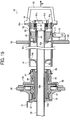
- Both ends of the heating roller 14 are supported by frames 50 and 50 of the fixing unit, respectively, via holding members 48 and 49 respectively having centering members 46 and 47.
- the centering member 46 is arranged on the holding member 48 via a shaft bearing 51, and is inserted to the inside of one opening end of the heating roller 14.
- the shaft bearing 51 can absorb thermal expansions of the heating roller 14 and variations in supporting members therearound by a plurality of springs 52 arranged along the circumferential direction and a stopper plate 53 attached on an inner end surface of the holding member 48.
- the springs 52 are slightly compressed and a gap is formed between the centering member 46 and the shaft bearing 51, and the stopper plate 53 as illustrated in Fig. 16 .
- the holding member 48 is fastened to one of the frames 50 by a plurality of thumbscrews 54.
- the holding member 49 is provided with a gear 55 that receives a driving force from a heating roller driving motor (not illustrated) that rotates the heating roller 14.
- the holding member 49 is rotatably supported by housings 58 and 59 via shaft bearings 56 and 57, respectively.
- a key groove (not illustrated) extending in the axial direction is formed on an opening end of the heating roller 14 facing to the centering member 47.
- a key (not illustrated) engaged into the key groove is formed on an end of the centering member 47.
- the heating roller 14 and the centering member 47 are coupled by these key structures. Therefore, the driving force of the heating roller driving motor is transferred to the heating roller 14 via the gear 55, the holding member 49, the centering member 47, and the key structures, to rotate the heating roller 14 in a predetermined direction.
- a ring 60 made of heat tolerant synthetic resin is interposed between each end of the heating roller 14 and each of the centering members 46 and 47 to prevent the heat on the heating roller 14 from leaking to the centering members 46 and 47, and to prevent damage.
- a groove-like cutout (not illustrated) is formed on the ring 60 on the centering member 47 side at a position corresponding to the key groove on the heating roller 14, so that the key can be engaged into the key groove.
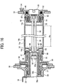
- the heater lamps 25 as the heat source of the heating roller 14 are bundled with lamp holders 61 and 62, respectively holding both ends of the heater lamps 25, to form a lamp cartridge 63.
- the lamp cartridge 63 is installed in the heating roller 14 at the center thereof, as illustrated in Fig. 16 .
- a protective pipe 64 which is made of paper or is formed with heat tolerant synthetic resin, is used in the manner illustrated in Fig. 17 .
- the outer diameter of the protective pipe 64 is designed to be approximately same in size as the internal diameter of the holding member 48, and the internal diameter of an internal tube 59b in the housing 59.
- the inner diameter of the protective pipe 64 is designed to be approximately same in size as the outer diameter of the lamp holder 62.
- the length of the protective pipe 64 is designed to be slightly longer than the distance between the frames 50 and 50 located at both sides.
- the lamp cartridge 63 is at first inserted into the protective pipe 64 from the lamp holder 62 side, up to where the right end of the protective pipe 64 abuts to an end surface of the other lamp holder 61 (see Fig. 17 ).
- the leading edge of the lamp holder 62 has a sloped portion 62a to allow the lamp holder 62 to be inserted into the protective pipe 64 more easily.
- the lamp cartridge 63 covered with the protective pipe 64 is inserted from the holding member 48 side (from the front side of the printer) as indicated by the arrow A in Fig. 17 .
- the protective pipe 64 passes through the insides of the holding member 48, the absorber 14c, the absorber 14d, and the internal tube 59b in the housing 59.
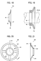
- Fig. 18 is a sectional view of the absorber 14d.
- the entire absorber 14d is approximately disk-shaped, and includes at the center a tubular sliding portion 85 extending in the axial direction of the heating roller 14.
- the sliding portion 85 and a periphery portion 86 of the absorber 14d are connected by a sloped portion 87 slightly sloping so that the sliding portion 85 is located closer to the opening of the heating roller 14 than the periphery portion 86, as illustrated in Fig. 17 .
- An insertion hole 88 is formed on inner side of the sliding portion 85.
- the inner diameter of the insertion hole 88 is designed to be approximately same in size as the outer diameter of the protective pipe 64.
- the axial length of the sliding portion 85 is set as 5 to 10 millimeters.
- the internal diameters of the hollow portion of the holding member 48, the insertion hole 88 of the absorber 14d, and the internal tube 59b of the housing 59 are designed to be approximately same in size as the outer diameter of the protective pipe 64, and the absorber 14d has the sloped portion 87 sloping toward the insertion hole 88. Therefore, the protective pipe 64 (lamp cartridge 63) can be inserted smoothly into the heating roller 14 without being wobbled in the inserting direction.
- the insertion of the lamp cartridge 63 stops where the outer circumference of the lamp holder 61 abuts to the holding member 48. At this time, the leading edge of the protective pipe 64 in the insertion direction protrudes to the outside of the machine from the housing 59. Therefore, the protective pipe 64 can be pulled out of the heating roller 14 in the direction of the arrow A by holding the protruding portion with a hand, and mounting of the lamp cartridge 63 is completed.
- the protective pipe 64 is inserted to a penetrating hole 59a of the housing 59 from the rear side of the printer in the direction pointed by the arrow B in Fig. 17 , and is guided by the internal tube 59b in the housing 59, the sloped portion 62a on the lamp holder 62, the sliding portion 85 (insertion hole 88) on the absorber 14d, and the holding member 48, up to where the leading edge of the protective pipe 64 in the insertion direction abuts to the end surface of the lamp holder 61.
- the lamp holder 62 is housed inside the protective pipe 64.
- the lamp cartridge 63 can be removed by further inserting the protective pipe 64, so that the lamp cartridge 63 is pressed out along with the protective pipe 64 in the direction pointed by the arrow B.
- a paper tube is suitable for the protective pipe 64 because a paper tube has a heat insulating property, and a certain level of mechanical strength, and also is cheap and can be procured easily.
- the sloped portion 87 provided on the absorber 14d not only functions as a guide when inserting the protective pipe 64 in the direction of the arrow A, but also to alleviate a temperature difference on the surface of the heating roller 14.
- the surface temperature at the edges of the paper-passing area Aw (see Fig. 16 ) on the heating roller 14 tend to be lower than that at the center of the paper-passing area Aw, and a temperature difference tends to occur between the edges and the center.
- the absorber 14d is disposed immediately outside of the paper-passing area Aw on the heating roller 14, and the absorber 14d has the sloped portion 87 extending toward the opening of the heating roller 14 (the end of the heater lamps 25) so that the heat generated at the end of the heater lamps 25 is collected at the sloped portion 87.
- the surface temperature at the edge of the paper-passing area Aw of the heating roller 14 increases and the temperature difference on the surface of the heating roller 14 can be alleviated advantageously.
- the sloped portion 87 is arranged on the absorber 14d.
- the sloped portion may be arranged on the absorber 14c.
- the replacement aid for the heating roller 14 will now be explained.
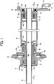
- the replacement aid according to the embodiment includes a guiding shaft 30, an assisting unit 40, and supporting roller members 70.
- the guiding shaft 30 is a straight pipe made of a rigid material such as aluminum (metal).
- the length of the guiding shaft 30 is slightly longer than the distance between the right and the left frames 50 and 50, as illustrated in Fig. 1 .
- the outer diameter of the guiding shaft 30 is approximately same in size as the internal diameter of the holding member 48, the inner diameter of the sliding portion 85 on one of the absorbers 14d (see Fig. 18 ), and the inner diameter of the internal tube 59b in the housing 59.
- An engaging groove 30a is formed circumferentially on the guiding shaft 30 near the trailing edge thereof in the insertion direction (see Fig. 2 ).
- a plate-like stopper 31 for fastening (locking) the guiding shaft 30 is held on the side of the housing 59 (the rear side of the printer) in a slidable manner by a pin 32.
- Fig. 2 is an enlarged partial sectional view of an engagement between the guiding shaft 30 and the stopper 31.
- Fig. 3 is an enlarged front view of the stopper 31.
- Fig. 4 is an enlarged side view of the stopper 31.
- a knob 31a bent horizontally is arranged at the top end of the stopper 31.
- An engaging piece 31b extending in an approximate semi-circular shape is arranged on the bottom end of the stopper 31.
- a sliding groove 31c extending in the vertical direction is arranged between the knob 31a and the engaging piece 31b.
- the knob 31a is used to bring up or down the stopper 31.
- the engaging piece 31b is engaged with the engaging groove 30a on the guiding shaft 30 to fasten (lock) the guiding shaft 30.
- the pin 32 is inserted in the sliding groove 31c.
- the inner diameter of the semi-circular engaging piece 31b is designed to be approximately same in size as the inner diameter of the bottom surface of the engaging groove 30a on the guiding shaft 30.
- the engaging groove 30a is formed extending circumferentially on the guiding shaft 30, and the stopper 31 is formed to include the engaging piece 31b extending in an approximate semi-circular shape. Therefore, the guiding shaft 30 can be freely inserted without limitation to the inserting direction of the guiding shaft 30 with respect to the stopper 31, as well as can be reliably fixed (lock) with the inner circumference of the engaging piece 31b.
- the stopper 31 is used to fix (lock) the guiding shaft 30 at a predetermined position, the heating roller 14 described later, the holding member 48, and the assisting unit 40 can be inserted and removed smoothly without causing the guiding shaft 30 to wobble.
- a sloped surface 30b is formed on the outer circumference of the guiding shaft 30 at the leading edge thereof in the insertion direction, to allow the assisting unit 40, for example, to be inserted smoothly.
- the leading edge of the guiding shaft 30 in the insertion direction protrudes slightly from the side of the frame 50 (see Fig. 5 ).
- the assisting unit 40 includes a unit body 45, two latches 41 arranged rotatably on a side of the unit body 45, shafts 42 for transferring movements of the latches 41 to holders 43, the holders 43 in each of which one end is coupled to the shafts 42 and the other end is bent outwardly, coil-like springs 44 for absorbing the tolerance of the components to secure fastening of the heating roller 14, a handle 66 attached to the side of the unit body 45, and push pins 90 (see Figs. 7A and 7B ).
- a penetrating hole 45b penetrating along the axial direction is provided at the center of the unit body 45.
- the inner diameter of the penetrating hole 45b is designed to be approximately same in size as the outer diameter of the guiding shaft 30.
- a flange 45c is formed on one side of the unit body 45.
- the two latches 41 are same in shape.
- Each of the latches 41 includes a semi-cylindrical rotating portion 41a formed on one end, an shaft 41b arranged inside the rotating portion 41a eccentrically in the thickness direction of the rotating portion 41a, and a lever 41c arranged on the opposite side of the rotating portion 41a.
- These two latches 41 are attached to the unit body 45 so as to face each other with the penetrating hole 45b interposed therebetween.
- one end of the shaft 42 is coupled to the shaft 41b of the latch 41.
- a nipping piece 43a which is bent so as to face to an inner surface 45a of the unit body 45.
- the coil-like spring 44 is interposed between a stepped spring receiving portion 45e arranged on the unit body 45 and the latch 41.
- the shaft 42 is inserted in the spring 44, and the latch 41 is constantly biased outwardly by resilience of the spring 44.
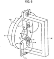
- the latch 41 is provided with a retaining unit 41d having a U shape laterally (see Fig. 6 ).
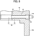
- the push pin 90 includes a large diameter portion 91 facing to the end surface of the heating roller 14 and a small diameter portion 92 facing to the lever 41c on the latch 41, as illustrated in Figs. 7A, 7B and 8 .
- a stepped portion 93 is formed on the boundary between the large diameter portion 91 and the small diameter portion 92.
- a retaining ring 94 is fastened near the head of the small diameter portion 92.
- the small diameter portion 92 of the push pin 90 is inserted into a penetrating hole 95 arranged in the unit body 45, and is disposed movably along the axial direction of the heating roller 14 by guidance of the penetrating hole 95.
- a sunken cutout 98 having an inner diameter larger than the outer diameter of the retaining ring 94 is formed on the end of the penetrating hole 95 facing to the latch 41.
- the stepped portion 93 of the push pin 90 faces to one of the opening ends of the penetrating hole 95, and the retaining ring 94 faces to the bottom surface of the sunken cutout 98. In this manner, the push pin 90 is prevented from falling out of (being disengaged from) the unit body 45 carelessly.
- the push pins 90 are arranged at positions facing to the end surface of the heating roller 14 via rings 60 (not illustrated), as illustrated by the small circles drawn denoted by the dotted lines in Figs. 9A and 9B , and facing to the lever 41c on the latches 41 as illustrated in Fig. 7A .
- the push pins 90 have a length such that, while the levers 41c of the latches 41 are held down inwardly with respect to each other, the small diameter portions 92 of the push pins 90 slightly protrude from an outer surface 45d of the unit body 45, and while the levers 41c of the latches 41 are held down outwardly with respect to each other as illustrated in Fig. 7A , the small diameter portions 92 of the push pins 90 are pressed by the levers 41c on the latches 41, and the large diameter portions 91 of the push pins 90 are caused to protrude from the outer circumference of the unit body 45.
- Fig. 7A illustrates the levers 41c on the two latches 41 placed outwardly with respect to each other.
- the shafts 41b of the latches 41 are brought near the unit body 45, and therefore, the gap (gap L) between the nipping pieces 43a of the holders 43 and the inner surface 45a of the unit body 45 becomes large as indicated as L1.
- the gap L1 is designed to be slightly wider than the thickness of the absorber 14c. In this positioning, the push pins 90 are pushed by the levers 41c on the latches 41 to cause the large diameter portions 91 to slightly protrude from the outer circumference of the unit body 45.
- the assisting unit 40 By reducing the gap L to the gap L2, the assisting unit 40 is fastened to the absorber 14c, and the heating roller 14 is integrated with the assisting unit 40. This allows these components to be removed from or inserted to the fixing unit 12. On the contrary, by increasing the gap L to the gap L1, the assisting unit 40 is released from the absorber 14c, and the large diameter portions 91 of the push pins 90 protrude from the outer circumference of the unit body 45. This causes the large diameter portions 91 to press the end surface of the heating roller 14 via the rings 60. The assisting unit 40 is thus separated from the heating roller 14 automatically.
- Figs. 9A and 9B are schematics illustrating a relationship between the absorber 14c and the nipping pieces 43a on the holders 43 taken along the arrow X-X in Fig. 10 .
- Fig. 9A is a schematic illustrating a state where the assisting unit 40 is inserted in the heating roller 14.
- Fig. 9B is a schematic illustrating a state just before attaching the assisting unit 40 to the absorber 14c.
- two cutouts 67 having the size allowing the nipping pieces 43a on the holder 43 to pass through are formed opposite to each other on the inner circumference of the absorber 14c.
- the nipping pieces 43a of the holders 43 pass through the cutouts 67. Insertion to the absorber 14c finishes when the flange 45c of the unit body 45 abuts to the outer surface of the frame 50.
- rotation allowing portions 96 communicatively connected to the cutouts 67 are formed on the center sides of the cutouts 67, along the rotation direction of the assisting unit 40 (the direction pointed by arrows). Stopping end surfaces 97 are formed in the back of the rotation allowing portions 96.
- FIG. 9A is a schematic illustrating the leading edges of the roots 43b just before hitting the stopping end surfaces 97.
- the stopping end surfaces 97 are arranged at positions allowing the assisting unit 40 to stop automatically when the assisting unit 40 is rotated by approximately 30 to 60 degrees (30 degrees in this embodiment) in the direction pointed by the arrows from the position illustrated in Fig. 9A .
- the supporting roller member 70 includes a supporting roller 71, a first shaft 72 rotatably supporting the supporting roller 71, a roller plate 73 fixing the first shaft 72 on one of free ends thereof, a second shaft 74 arranged on the base end of the roller plate 73, and a holder plate 75 rotatably supporting the second shaft 74.
- the heating roller 14 at a high temperature of approximately 200 degrees Celsius is carried on the supporting rollers 71 when the heating roller 14 is replaced. Therefore, the supporting rollers 71 are highly heat tolerant, and made of the same material or a material of the same system as the surface layer 14b of the heating roller 14 (see Fig. 16 ) so that the surface layer 14b is not damaged thereby.
- the surface layer 14b of the heating roller 14 is formed with a fluorine-based resin such as polytetrafluoroethylene (PTFE) resin, tetrafluoroethylene / perfluoro-alkyl-vinyl-ether copolymer (PFA) resin, or tetrafluoroethylene hexafluoropropylene copolymer (fluorinated ethylene propylene (FEP)) resin.
- PTFE polytetrafluoroethylene
- PFA perfluoro-alkyl-vinyl-ether copolymer
- FEP tetrafluoroethylene hexafluoropropylene copolymer
- the supporting rollers 71 are also made of the same material or a material of the same system (fluorine-based resin in the embodiment).
- the supporting rollers 71 are shaped drum-like so that the surface of the heating roller 14 is kept in point contact with the surface of the supporting roller 71.
- a hook 76 is formed integrally by bending.
- a groove 77 into which the hook 76 engaged (fitted) is formed on the holder plate 75 (see Fig. 11E ).
- the width of the groove 77 is set to a size that is approximately same as the thickness of the hook 76.
- the roller plate 73 is supported thereby in a vertically movable manner, which is described later.
- Figs. 11A and 11B are respectively a side view and a front view of positioning of the supporting roller member 70, when the heating roller 14 is pulled out of or inserted into the printer.
- the hook 76 arranged on the roller plate 73 is inserted (locked) in the groove 77 on the holder plate 75 to keep the roller plate 73 upright.
- the supporting roller 71 faces a replacement opening 82 arranged on the frame 50, as illustrated in Fig. 15 .
- Figs. 11C and 11D are respectively a side view and a front view of the supporting roller member 70 when the supporting roller member 70 is moved from a working position explained above toward a standby position explained below.
- the roller plate 73 is pulled up in the direction pointed by the arrow E to take the hook 76 off of the groove 77 (releasing the lock), and the roller plate 73 is then rotated about the second shaft 74 by approximately 180 degrees in the direction pointed by the arrow F.
- Figs. 11E and 11F are respectively a side view and a front view of the supporting roller member 70 at the standby position. In this position, the roller plate 73 is hanging from the second shaft 74. Therefore, the supporting roller 71 is located at a lower position, and is at the standby position away from the replacement opening 82 on the frame 50 (see Fig. 1 ).
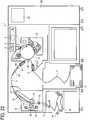
- Fig. 12 is a schematic showing arrangements of the supporting roller members 70 with respect to the assisting unit 40.
- two supporting roller members 70a and 70b are used, and are arranged at positions near the replacement opening 82 on the frame 50 so that the heating roller 14 can be pulled out smoothly by holding the handle 66 on the assisting unit 40.
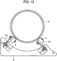
- a vertical line 79 passing through a center "O" of the heating roller 14 is zero degree as illustrated in Fig. 12 , and that the two supporting roller members 70a and 70b are specifically installed under the heating roller 14.
- center lines 80 which are perpendicular to the axes of supporting rollers 71a and 71b, respectively, cross at an angle (angle ⁇ ) between ⁇ 30 to ⁇ 60 degrees with respect to the vertical line 79, or more preferably between ⁇ 40 to ⁇ 50 degrees (45 degrees in this embodiment).
- the supporting roller members 70a and 70b are arranged at symmetrical positions with respect to the vertical line 79. In this manner, when the heating roller 14 is pulled out with an aid of the assisting unit 40, the supporting roller members 70a and 70b can stably support the heating roller 14 to eliminate factors of instability without obstructing the operation.
- the supporting roller members 70a and 70b are attached to an attaching plate 81 at the symmetrical positions, and the supporting roller members 70a and 70b are fixed to the outside of the frame 50 via the attaching plate 81 (see Fig. 1 ).
- the two supporting roller members 70 are arranged under the heating roller 14.
- such supporting roller members 70 should be arranged at positions such that, when the heating roller 14 is pulled out with an aid of the assisting unit 40, such pulling operation is not obstructed thereby, in the same manner as the supporting roller members 70a and 70b arranged downward.
- the supporting roller member 70 arranged upward must have a predetermined gap with respect to the heating roller 14 to avoid giving too much constraint to the heating roller 14.
- the heating roller 14 is replaced when the heating roller 14 has ended its life, or is replaced to a different heating roller 14 that can satisfy a need required to the printer.
- Fig. 14 is a flowchart of steps of replacing the heating roller 14. As illustrated in Fig. 14 , at Step S1, the lamp cartridge 63 is pulled out of the heating roller 14 by using the protective pipe 64. This operation is performed in the way that has been explained above with reference to Fig. 17 . Therefore, a redundant explanation thereof is omitted herein. Because the lamp cartridge 63 is protected by the rigid protective pipe 64 while the lamp cartridge 63 is in the protective pipe 64, the lamp cartridge 63 is not damaged carelessly during the replacement.
- the guiding shaft 30 is inserted into the penetrating hole 59a in the housing 59 (from the rear side of the printer), as illustrated in Fig. 1 , in the direction pointed by the arrow B.
- the guiding shaft 30 penetrates while being guided and held by the internal tube 59b in the housing 59, the sliding portion 85 of the absorber 14d, and the holding member 48.
- the stopper 31 is inserted to the engaging groove 30a on the guiding shaft 30 (see Fig. 2 ) and mounting of the guiding shaft 30 is completed.
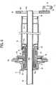
- Step S3 the thumbscrew 54 is loosened and the holding member 48 holding components such as the centering member 46, the shaft bearing 51, the springs 52, and the stopper plate 53 is pulled out in the direction pointed by the arrow B. Because the leading edge of the guiding shaft 30 slightly protrudes from the outer surface of the frame 50, the holding member 48 can be pulled out smoothly while being guided by the guiding shaft 30, without colliding to the edge of the opening of the frame 50. By the centering member 46 parting from the heating roller 14 as the holding member 48 is pulled out, the centering member 46 and the shaft bearing 51 abut to the stopper plate 53 due to resiliency of the springs 52.
- FIG. 5 is a schematic showing the heating roller 14 from which the holding member 48 is pulled out.
- Step S4 the assisting unit 40 is inserted to the guiding shaft 30 from the leading edge thereof having the sloped surface 30b by holding the handle 66.
- the levers 41c on the latches 41 are kept opened outwardly with respect to each other. Therefore, the gap between the inner surface 45a of the unit body 45 and a nipping piece 43a of the holder 43 is set to the gap L1 that is wider.
- the large diameter portions 91 of the push pins 90 protrude from the outer circumference of the unit body 45.
- the nipping piece 43a of the holder 43 passes through the cutouts 67 on the absorber 14c, as illustrated in Fig. 9A , and go inside of the absorber 14c.
- the insertion of the assisting unit 40 stops where the large diameter portions 91 of the push pins 90 abut to the ring 60.
- Step S5 the supporting rollers 71 are moved to and locked in the working position.
- the roller plates 73 illustrated in Fig. 11E are rotated by 180 degrees in the opposing direction from the direction indicated by the arrow F, and the hooks 76 are fitted into the grooves 77.
- the supporting rollers 71 face to the replacement opening 82 on the frame 50 as illustrated in Fig. 15 .
- Step S6 the heating roller 14 that is still in a high temperature is pulled out of the printer by holding the handle 66 on the assisting unit 40.
- the guiding shaft 30 is reliably held in the internal tube 59b in the housing 59, and the sliding portion 85 on the absorber 14d slides on the outer circumference of the guiding shaft 30.
- a part of the heating roller 14 coming out of the frames 50 is stably supported by the supporting rollers 71a and 71b, and the supporting rollers 71a and 71b rotate as the heating roller 14 is pulled out.
- Fig. 13 illustrates how the heating roller 14 is supported. As illustrated in Fig. 13 , the heating roller 14 is supported by the supporting rollers 71a and 71b at two point contacts "P". In this manner, a part of the heating roller 14 at high temperature of approximately at 200 degrees Celsius does not have to be supported with a hand, to allow the heating roller 14 to be pulled out smoothly and safely.
- FIG. 15 illustrates the heating roller 14 being pulled out.
- the standing supporting rollers 71 are positioned closer to the frame 50 than the leading edge of the guiding shaft 30. Therefore, the outer circumference of the heating roller 14 is held on the supporting rollers 71 until the trailing edge of the heating roller 14 in the removing direction comes off of the leading edge of the guiding shaft 30.
- the assisting unit 40 is attached to a new heating roller 14 to be replaced (not illustrated), and the assisting unit 40 and the heating roller 14 are mounted by using the guiding shaft 30.
- the supporting rollers 71a and 71b are used in mounting as well, and the sliding portion 85 of the absorber 14d mounted on the new heating roller 14 slides on the outer circumference of the guiding shaft 30 until the heating roller 14 is smoothly inserted into a predetermined position.
- Step S8 the supporting rollers 71a and 71b are unlocked, and moved to the standby position. Because unlocking and moving the supporting rollers 71a and 71b to the standby position are explained earlier with reference to Figs. 11A to 11F , redundant explanations thereof are omitted herein.
- the assisting unit 40 is removed from the heating roller 14.
- the holding member 48 is mounted using the guiding shaft 30.
- the stopper 31 is removed and the guiding shaft 30 is pulled out.
- the lamp cartridge 63 covered with the protective pipe 64 is inserted into the heating roller 14, and then the holding member 48 is pulled out of the heating roller 14 to complete mounting of the lamp cartridge 63.
- the step of mounting the new heating roller 14 at Step S7 is a reverse of the step of removing the heating roller 14 at Step S6, and the step of removing the assisting unit 40 at Step S9 is the reverse of the step of mounting the assisting unit 40 at Step S4.
- the large diameter portions 91 of the push pins 90 protrude from the outer circumference of the unit body 45 to press the end surface of the heating roller 14 via the ring 60. In this manner, the assisting unit 40 can be separated from the heating roller 14 easily and quickly.
- the step of mounting the holding member 48 at Step S10 is a reverse of the step of pulling out the holding member 48 at Step S3, and the step of pulling out the guiding shaft 30 at Step S11 is the reverse of the step of mounting the guiding shaft 30 at Step S2.
- the step of mounting the lamp cartridge 63 at Step S12 is the reverse of the step of pulling out the lamp cartridge 63 at Step S1. Therefore, redundant explanations thereof are omitted herein.
- Fig. 19 is an enlarged sectional view a part of the absorber 14d according to a further embodiment of the present invention.
- a heat tolerant resin layer 99 is arranged to the sliding portion 85 of the absorber 14d at least on the inner circumference of that is brought into sliding contact with the guiding shaft 30 and the protective pipe 64.
- the heat tolerant resin layer 99 is made of an injection-molded body, and the injection-molded body is tightly fitted into the sliding portion 85 of the absorber 14d. It is also possible to provide coating of heat tolerant resin on the inner circumference of the sliding portion 85 to form the heat tolerant resin layer 99.
- the inner diameter of the heat tolerant resin layer 99 is designed to be approximately same in size as the outer diameters of the guiding shaft 30 and the protective pipe 64.
- the heat tolerant resin polyimide resin, polyamide imide resin, polyphenylene oxide resin, polysulfone resin, or fluorine resin is used, for example.
- the heat tolerant resin layer 99 on the part being brought in sliding contact with the guiding shaft 30 and the protective pipe 64, the guiding shaft 30 and the protective pipe 64 can be inserted and removed more smoothly by slipping property of the heat tolerant resin layer 99, and uncomfortable sliding sound can be eliminated.
- Fig. 20 is a front view of a shaft sliding member according to a further embodiment of the present invention.
- Fig. 21 is a sectional view taken along the line Y-Y in Fig. 20 .
- a shaft sliding member also functions as the heat release preventing member (absorber).
- This embodiment relates to a shaft sliding member that does not function as the heat release preventing member (absorber), and is mounted on the pressing roller 15 not having a heat source inside, for example (see Fig. 23 ).
- a shaft sliding member 200 includes an outer ring 201 fixed on the inner circumference of the pressing roller 15 with an adhesive or the like, a sliding portion 202 into which the guiding shaft 30 is inserted, and a plurality of connecting ribs 203 extending in the radial direction of the shaft sliding member 200 to connect the outer ring 201 and the sliding portion 202.
- the spaces between the connecting ribs 203 are kept as spaces 204 to reduce the weight of and the amount of material used in the shaft sliding member 200.
- the inner diameter of the sliding portion 202 is designed to be approximately same in size as the outer diameter of the guiding shaft 30.
- the connecting ribs 203 are sloped from the outer ring 201 to the sliding portion 202 in order to function as a guide when the leading edge of the guiding shaft 30 is inserted into the sliding portion 202.
- the shaft sliding member 200 is formed of heat tolerant resin, such as polyimide resin, polyamide-imide resin, polyphenylene oxide resin, polysulfone resin, or fluorine resin.
- the absorber 14d and the shaft sliding member 200 are provided with the cylindrical sliding portions 85 and 202 continuous in the circumferential direction to act as the shaft sliding member.
- the sliding portion does not necessarily have to be continuous in the circumferential direction.
- the sliding portion may have a plurality of slits along the circumferential direction so as to slide on the outer circumference of the guiding shaft 30 elastically.
- Figs. 22A to 22C are partial side views illustrating the nipping pieces 43a in the assisting unit 40 nipping the inner circumference of the absorber 14c according to still a further embodiment of the present invention. Because the absorber 14c is located inside of the heating roller 14, after inserting the nipping pieces 43a in the assisting unit 40 into the cutouts 67 on the absorber 14c and rotating the assisting unit 40, it is not possible to check from outside of the heating roller 14 if the nipping pieces 43a are apart from the cutouts 67 and face the other inner circumference of the absorber 14c.
- a unit-side mark 205 is provided by way of printing, for example, on the outer circumference of the unit body 45 in the assisting unit 40 at a position in the inserting-direction on the leading edge side of the assisting unit 40, as illustrated in Figs. 22A to 22C .
- a first roller-side mark 206, a second roller-side mark 207, and an arrow mark 208 pointing from the first roller-side mark 206 to the second roller-side mark 207 are provided by way of printing, for example, near the opening of the heating roller 14 on the outer circumference thereof.
- the first roller-side mark 206, the second roller-side mark 207, and the arrow mark 208 are provided at positions on the outer circumference of the heating roller 14 and outside of the paper-passing area Aw (see Fig. 16 ).
- the first roller-side mark 206 is provided at a position so that, when the assisting unit 40 is inserted into the opening of the heating roller 14 so as to bring the unit-side mark 205 on the assisting unit 40 in alignment with the first roller-side mark 206 as illustrated in Fig. 22B , the nipping pieces 43a in the assisting unit 40 are exactly inserted into the cutouts 67 on the absorber 14c as illustrated in Fig. 9A .
- the second roller-side mark 207 is arranged at a position so that, when the assisting unit 40 is rotated in the direction indicated by the arrow mark 208 so as to align the unit-side mark 205 to the second roller-side mark 207, the nipping pieces 43a in the assisting unit 40 are parted completely from the cutouts 67 on the absorber 14c, and face to the inner circumference of the absorber 14c excluding the cutouts 67.
- Figs. 22A to 22C are schematics of such sequential operations.
- the assisting unit 40 is inserted into the opening of the heating roller 14 so that the unit-side mark 205 is aligned with the first roller-side mark 206.
- Fig. 22B when the unit-side mark 205 is aligned with the first roller-side mark 206, it can be confirmed that the nipping pieces 43a in the assisting unit 40 are exactly inserted into the cutouts 67 on the absorber 14c.
- the length of the unit-side mark 205 is set so that a part of the unit-side mark 205 remains visible from the opening of the heating roller 14, even when the assisting unit 40 is inserted into the opening of the heating roller 14.
- the assisting unit 40 is then rotated in the direction pointed by the arrow mark 208, that is, the direction toward which the rotation allowing portions 96 (see Fig. 9A ) are arranged, and the rotation is stopped at the point where the unit-side mark 205 is aligned with the second roller-side mark 207. Because the stopping end surfaces 97 are formed in the back of the rotation allowing portions 96 as described in the above embodiment, it can be confirmed visually that the unit-side mark 205 and the second roller-side mark 207 are aligned, as well as be confirmed with feel that the roots 43b of the nipping pieces 43a abut to the stopping end surfaces 97.
- a cylindrical sliding portion is arranged in the inner circumference of the sliding member.
- the sliding member may be simpler in shape, where the sliding member is made from a plate-like material, and an insertion hole for inserting the guiding shaft is formed at the center of the sliding member to use circumference of the insertion hole as the sliding portion. It is preferable to round the edge of the opening of the insertion hole so that the guiding shaft can be inserted easily.
- the absorber 14c is used to connect the heating roller 14 to the assisting unit 40.
- the heating roller 14 may be provided with a fitting portion (e.g., a recess, a projection, or a hole) dedicated to the connection to the assisting unit 40, and the heating roller 14 and the assisting unit 40 may be connected together by using the fitting portion dedicated to the connection.
- the heating roller 14 is explained to be replaced.
- the present invention can also be applied in replacement of the pressing roller 15 containing or not containing a heat source.
- the parting agent or the lubricant is applied on the heating roller 14.
- the present invention can also be applied to a fixing unit (image forming apparatus) in which the parting agent or the lubricant is applied on the pressing roller 15, or both of the heating roller 14 and the pressing roller 15.
- the present invention is structured as described above, and can provide a fixing roller for a fixing unit, a fixing unit, an image forming apparatus, a replacement aid for a fixing roller in a fixing unit, and a method of replacing a fixing roller in a fixing unit that can overcome the disadvantages of the conventional technology and enable a fixing roller to be replaced easily and safely.
Landscapes
- Physics & Mathematics (AREA)
- General Physics & Mathematics (AREA)
- Fixing For Electrophotography (AREA)
Claims (15)
- Fixierwalze, genutzt für eine Fixiereinheit (12), wobei die Fixiereinheit (12) eine Heizwalze (14) und eine Presswalze (15) hat, die pressfähig gegen die Heizwalze (14) angeordnet ist und ein Aufzeichnungsmedium erhitzt und presst, das ein nicht fixiertes Tonerbild auf einer Oberfläche davon hält, während es das Aufzeichnungsmedium zwischen der Heizwalze (14) und der Presswalze (15) einklemmt und fördert, um dadurch ein Tonerbild auf dem Aufzeichnungsmedium zu fixieren, wobei
die Fixierwalze mindestens eine der Heizwalze (14) und der Presswalze (15) ist, die auswechselbar in der Fixiereinheit (12) entlang einer Axialrichtung der Fixierwalze gestützt ist, und
die Fixierwalze ein Gleitelement (14d) umfasst, das einstückig zu einer Innenseite der Fixierwalze gebildet ist; wobei
das Gleitelement (14d) konfiguriert ist, um an einem Außenumfang eines Walzenführungsschachts (30) zu gleiten, der bei einem Austauschen der Fixierwalze in die Fixierwalze eingesetzt und aus der Fixierwalze entfernt wird, und
dadurch gekennzeichnet, dass:ein Unterstützungseinheitsverbindungselement (14c), an das eine Unterstützungseinheit (40) zum Entfernen der Fixierwalze abnehmbar anbringbar ist, an einem Vorderkantenabschnitt der Fixierwalze in einer Entnahmerichtung bereitgestellt ist, unddas Gleitelement (14d) nahe einer Öffnung der Fixierwalze dem Unterstützungseinheitsverbindungselement (14c) entgegengesetzt angeordnet ist, undwobei das Unterstützungseinheitsverbindungselement (14c) umfasst:eine Aussparung (67), durch die ein Einklemmteil (43a), das auf der Unterstützungseinheit (40) angeordnet ist, eingesetzt werden kann;einen drehungserlaubenden Abschnitt (96), der kommunikativ mit der Aussparung (67) verbunden ist und konfiguriert ist, um dem Einklemmteil (43a), dass durch die Aussparung einsetzbar ist, zu erlauben, durch die Aussparung (67) in einem vorbestimmten Winkel gedreht zu werden; undeinen Anschlagabschnitt (97), der konfiguriert ist, eine Drehung des Einklemmteils (43a) zu stoppen, wenn das Einklemmteil (43a) an ein Ende des drehungserlaubenden Abschnitts (96) anstößt. - Fixierwalze für eine Fixiereinheit (12) nach Anspruch 1, wobei
das Gleitelement (14d) annähernd scheibenförmig ist,
die Fixierwalze eine Heizquelle (63) enthält, und
das Gleitelement (14d) auch als ein Wärmeabgabeverhinderungselement fungiert, das konfiguriert ist, zu verhindern, dass Strahlungswärme aus der Heizquelle (63) außerhalb der Fixierwalze freigesetzt wird. - Fixierwalze für eine Fixiereinheit (12) nach Anspruch 2, wobei das Gleitelement (14d) außerhalb eines Papierdurchgangsbereichs (Aw) auf der Fixierwalze angeordnet ist.
- Fixierwalze für eine Fixiereinheit (12) nach Anspruch 3, wobei das Gleitelement (14d) einen geneigten Abschnitt (87) enthält, der zwischen einem Außenumfang und einem Innenumfang des Gleitelements (14d) angeordnet ist, der geneigte Abschnitt ist so geneigt, dass der Außenumfang des Gleitelements (14d) näher an einer Öffnung der Fixierwalze als der Innenumfang ist.
- Fixierwalze für eine Fixiereinheit (12) nach einem der Ansprüche 1 bis 4, wobei eine hitzetolerante Harzschicht (99) auf einem Innenumfang des Gleitelements (14d) angeordnet ist.
- Fixierwalze für eine Fixiereinheit (12) nach einem der Ansprüche 1 bis 5, wobei
das Unterstützungseinheitsverbindungselement (14c) annähernd scheibenförmig ist,
die Fixierwalze eine Heizquelle (63) enthält, und
das Unterstützungseinheitsverbindungselement (14c) auch konfiguriert ist, als ein Wärmeabgabeverhinderungselement zu fungieren, das angepasst ist, zu verhindern, dass Strahlungswärme aus der Heizquelle (63) außerhalb der Fixierwalze freigesetzt wird. - Fixierwalze für eine Fixiereinheit (12) nach Anspruch 6, wobei das Unterstützungseinheitsverbindungselement (14c) außerhalb eines Papierdurchgangsbereichs (Aw) auf der Fixierwalze angeordnet ist.
- Fixiereinheit (12), umfassend:eine Heizwalze (14); undeine Presswalze (15), die pressfähig gegen die Heizwalze (14) angeordnet ist, wobeidie Fixiereinheit (12) ein Aufzeichnungsmedium erhitzt und presst, das ein nicht fixiertes Tonerbild auf einer Oberfläche davon hält, während es das Aufzeichnungsmedium zwischen der Heizwalze (14) und der Presswalze (15) einklemmt und fördert, um dadurch das Tonerbild auf dem Aufzeichnungsmedium zu fixieren, wobeimindestens eine der Heizwalze (14) und der Presswalze (15) als eine Fixierwalze bereitgestellt ist und in der Fixiereinheit (12) auswechselbar entlang einer Axialrichtung der Walze gestützt ist, unddie auswechselbar gestützte Fixierwalze in der Fixiereinheit (12) die Fixierwalze für die Fixiereinheit (12) nach einem der Ansprüche 1 bis 7 ist.
- Fixiereinheit (12) nach Anspruch 8, ferner umfassend:ein Wellenlager (51, 56, 57), das drehbar ein Ende der auszuwechselnden Fixierwalze trägt;ein Wellenlagerhalteelement (48, 49), das das Wellenlager (51, 56, 57) hält; undein Innenrohr, dass innerhalb des Wellenlagerhalteelements (48, 49) angeordnet ist, um einen Walzenführungsschacht (30) zu halten, der konfiguriert ist, eine Einführung und eine Entfernung der Fixierwalze während eines Einführens in die Innenseite des Wellenlagerhalteelements (48, 49) zu der Innenseite der Fixierwalze beim Austauschen der Fixierwalze zu führen.
- Fixiereinheit (12) nach Anspruch 9, ferner umfassend eine Sperre (30a, 30b, 31, 32), die konfiguriert ist, eine Verschiebung des Walzenführungsschachts (30) bei einem Auswechseln der Fixierwalze zu verhindern.
- Bilderzeugungsgerät, umfassend:eine Übertragungseinheit (10), die konfiguriert ist, ein Tonerbild auf einem Bildträger auf ein Aufzeichnungsmedium zu übertragen; unddie Fixiereinheit (12) nach einem der Ansprüche 8 bis 10.
- Walzenauswechselhilfe für eine Fixiereinheit (12), wobei mindestens eine von einer Heizwalze (14) und einer Presswalze (15), die pressfähig gegen die Heizwalze (14) angeordnet ist, als eine Fixierwalze bereitgestellt ist und durch Ausziehen entlang einer Axialrichtung auswechselbar ist, wobei die Walzenauswechselhilfe dadurch gekennzeichnet ist, dass sie umfasst:einen Walzenführungsschacht (30), der abnehmbar an die Fixiereinheit (12) anbringbar ist, um ein Gleitelement (14d) zu durchdringen, das innerhalb der auszuwechselnden Fixierwalze bereitgestellt ist und einen Außenumfang hat, auf dem das Gleitelement (14d) konfiguriert ist, bei einem Einfügen und einem Entfernen der Fixierwalze zu gleiten; undeine Unterstützungseinheit (40), die abnehmbar an ein Unterstützungseinheitsverbindungselement (14c) anbringbar ist, die zu einem Vorderkantenabschnitt der auszuwechselnden Walze in einer Entnahmerichtung angeordnet ist und auf einem Ende des Walzenführungsschachts (30) montiert ist, um der Fixierwalze zu erlauben, eingesetzt und entfernt zu werden,wobei das Unterstützungseinheitsverbindungselement (14c) umfasst:eine Aussparung (67), durch die ein Einklemmteil (43a), das auf der Unterstützungseinheit (40) angeordnet ist, eingesetzt wird;ein drehungserlaubender Abschnitt (96), der kommunikativ mit der Aussparung (67) verbunden ist und dem Einklemmteil (43a) erlaubt, einsetzbar durch die Aussparung (67) in einem vorbestimmten Winkel gedreht zu werden; undeinen Anschlagabschnitt (97), der konfiguriert ist, eine Drehung des Einklemmteils (43a) zu stoppen, wenn das Einklemmteil (43a) an ein Ende des drehungserlaubenden Abschnitts (96) anstößt.
- Verfahren zum Austauschen einer Fixierwalze in einer Fixiereinheit (12), wobei mindestens eine von einer Heizwalze (14) und einen Presswalze (15), die pressfähig gegen die Heizwalze (14) angeordnet sind, als eine Fixierwalze bereitgestellt ist und durch Ausziehen entlang einer Axialrichtung davon ausgetauscht wird, wobei das Verfahren dadurch gekennzeichnet ist, dass es umfasst:Einführen eines Walzenführungsschachts (30), der angebracht ist, um ein Gleitelement (14d) zu durchdringen, das innerhalb der auszuwechselnden Fixierwalze bereitgestellt ist;Ausziehen eines Halteelements, das ein Wellenlager (51, 56, 57) hat, das drehbar ein Ende der auszuwechselnden Fixierwalze entlang des Walzenführungsschachts (30) trägt;Verbinden einer Unterstützungseinheit (40) mit einem Unterstützungseinheitsverbindungselement (14c), das an einer Vorderkante der Fixierwalze in eine Entnahmerichtung angeordnet ist, durch Einsetzen der Unterstützungseinheit (40) entlang des Walzenführungsschachts (30);Ausziehen der Fixierwalze, die mit der Unterstützungseinheit (40) verbunden ist, durch das Erlauben, dass die Fixierwalze auf einen Außenumfang des Walzenführungsschachts (30) über das Gleitelement (14d) gleitet;Verbinden der Unterstützungseinheit (40) mit einem Unterstützungseinheitsverbindungselement (14c) einer neuen Walze, um die neue Walze, mit der die Unterstützungseinheit (40) verbunden ist, durch ein Erlauben, dass die neue Walze auf dem Außenumfang des Walzenführungsschachts (30) über das Gleitelement (14d) gleitet;Ausziehen der Unterstützungseinheit (40) entlang des Walzenführungsschachts (30) mit Trennen der Unterstützungseinheit (40) von der neuen derart aufgesetzten Walze;Aufsetzen eines Halteelements, das ein Wellenlager (51, 56, 57) hat, das drehbar ein Ende der neuen Walze entlang des Walzenführungsschachts (30) trägt; undAusziehen des aufgesetzten Walzenführungsschachts (30);wobei das Unterstützungseinheitsverbindungselement (14c) umfasst:eine Aussparung (67), durch die ein Einklemmteil (43 a), das auf der Unterstützungseinheit (40) angeordnet ist, eingesetzt wird;einen drehungserlaubenden Abschnitt (96), der kommunikativ mit der Aussparung (67) verbunden ist und dem Einklemmteil (43a) erlaubt, das durch die Aussparung (67) einsetzbar ist, in einem vorbestimmten Winkel gedreht zu werden; undeinen Anschlagabschnitt (97), der die Drehung des Einklemmteils (43a) stoppt, wenn das Einklemmteil (43a) an ein Ende des drehungserlaubenden Abschnitts (96) anstößt.
- Fixierwalze für eine Fixiereinheit (12) nach Anspruch 1, wobei die Fixierwalze auf ihrem Außenumfang eine Markierung (207) hat, die derart an einer Position angeordnet ist, dass, wenn die Unterstützungseinheit (40) gedreht wird, um eine zweite Markierung (205) auf dem Außenumfang der Unterstützungseinheit (40) an der Markierung (207) auszurichten, das Einklemmteil (43a) in der Unterstützungseinheit (40) komplett von der Aussparung (67) auf dem Unterstützungseinheitsverbindungselement (14c) getrennt wird und dem Innenumfang des Unterstützungseinheitsverbindungselement (14c) gegenüberliegt, ausgenommen der Aussparung (67).
- Fixierwalze für eine Fixiereinheit (12) nach Anspruch 1, wobei die hitzetolerante Harzschicht (99) beliebig aus einem von Polyimidharz, Polyamid-Imid-Harz, Polyphenylenoxidharz, Polysulfonharz und Fluorharz gebildet ist.
Applications Claiming Priority (1)
| Application Number | Priority Date | Filing Date | Title |
|---|---|---|---|
| JP2009199997A JP5402408B2 (ja) | 2009-08-31 | 2009-08-31 | 定着装置用ローラ、定着装置、画像形成装置、定着装置のローラ交換補助具、定着装置のローラ交換方法 |
Publications (3)
| Publication Number | Publication Date |
|---|---|
| EP2290468A2 EP2290468A2 (de) | 2011-03-02 |
| EP2290468A3 EP2290468A3 (de) | 2011-11-09 |
| EP2290468B1 true EP2290468B1 (de) | 2018-05-23 |
Family
ID=43062502
Family Applications (1)
| Application Number | Title | Priority Date | Filing Date |
|---|---|---|---|
| EP10251465.0A Active EP2290468B1 (de) | 2009-08-31 | 2010-08-19 | Fixierwalze für Fixiereinheit, Fixiereinheit, Bilderzeugungsvorrichtung, Walzenaustauschhilfe für die Fixiereinheit und Verfahren zum Austauschen der Fixierwalze in der Fixiereinheit |
Country Status (4)
| Country | Link |
|---|---|
| US (1) | US8364062B2 (de) |
| EP (1) | EP2290468B1 (de) |
| JP (1) | JP5402408B2 (de) |
| CN (1) | CN102004428B (de) |
Families Citing this family (8)
| Publication number | Priority date | Publication date | Assignee | Title |
|---|---|---|---|---|
| JP5532963B2 (ja) * | 2010-01-27 | 2014-06-25 | 株式会社リコー | 定着装置ならびにそれを備えた画像形成装置 |
| JP5423448B2 (ja) * | 2010-02-05 | 2014-02-19 | 株式会社リコー | 定着装置の部品交換補助具 |
| JP5552943B2 (ja) * | 2010-07-29 | 2014-07-16 | 株式会社リコー | 定着装置及び画像形成装置 |
| JP6282141B2 (ja) * | 2014-03-03 | 2018-02-21 | キヤノン株式会社 | 定着装置 |
| CN105235348A (zh) * | 2014-07-08 | 2016-01-13 | 中信国安盟固利动力科技有限公司 | 耐热橡胶与金属复合加热块及其制备方法和应用 |
| US9498992B2 (en) * | 2014-12-09 | 2016-11-22 | Panasonic Intellectual Property Management Co., Ltd. | Sheet material cooling device and printer including the same |
| CN109624485B (zh) * | 2019-01-28 | 2020-08-11 | 汕头市精工东捷制版有限公司 | 一种凹印机印刷版辊 |
| CN114167704B (zh) * | 2021-11-24 | 2023-05-30 | 长城信息股份有限公司 | 一种激光打印机定影单元加热装置 |
Family Cites Families (11)
| Publication number | Priority date | Publication date | Assignee | Title |
|---|---|---|---|---|
| EP0505404B1 (de) * | 1989-12-13 | 1994-06-01 | Siemens Nixdorf Informationssysteme Aktiengesellschaft | Fixierstation für eine elektrofotografische druck- oder kopiereinrichtung |
| DE4209520C1 (de) * | 1992-03-24 | 1993-04-08 | Siemens Nixdorf Informationssysteme Ag, 4790 Paderborn, De | |
| DE10056939C2 (de) | 1999-11-19 | 2003-02-20 | Hitachi Koki Kk | Lampenhalter und Lampenkartusche, die den Halter verwendet und Fixiereinheit, die den Halter verwendet |
| JP3900403B2 (ja) * | 2001-03-16 | 2007-04-04 | リコープリンティングシステムズ株式会社 | 定着装置 |
| JP2003302801A (ja) * | 2002-04-12 | 2003-10-24 | Hitachi Printing Solutions Ltd | ベルト搬送装置 |
| JP2004219491A (ja) | 2003-01-09 | 2004-08-05 | Ricoh Co Ltd | 定着ユニットに使用するローラ |
| JP4591254B2 (ja) | 2005-07-26 | 2010-12-01 | ブラザー工業株式会社 | 画像形成装置 |
| US8135307B2 (en) | 2007-06-22 | 2012-03-13 | Ricoh Company, Ltd. | Transfer belt device, method of assembling the same, and image forming apparatus |
| US8249486B2 (en) * | 2009-01-08 | 2012-08-21 | Ricoh Company, Ltd. | Fixing unit, roller replacement auxiliary tool of fixing unit, and image forming apparatus |
| JP5428470B2 (ja) | 2009-03-31 | 2014-02-26 | 株式会社リコー | 定着装置およびそれを備えた画像形成装置 |
| JP5593656B2 (ja) | 2009-01-08 | 2014-09-24 | 株式会社リコー | 定着装置、定着装置のローラ交換補助具、定着装置のローラ交換方法、画像形成装置 |
-
2009
- 2009-08-31 JP JP2009199997A patent/JP5402408B2/ja not_active Expired - Fee Related
-
2010
- 2010-08-17 US US12/805,724 patent/US8364062B2/en active Active
- 2010-08-19 EP EP10251465.0A patent/EP2290468B1/de active Active
- 2010-08-30 CN CN2010102685984A patent/CN102004428B/zh active Active
Non-Patent Citations (1)
| Title |
|---|
| None * |
Also Published As
| Publication number | Publication date |
|---|---|
| EP2290468A3 (de) | 2011-11-09 |
| US20110052258A1 (en) | 2011-03-03 |
| EP2290468A2 (de) | 2011-03-02 |
| CN102004428A (zh) | 2011-04-06 |
| JP2011053304A (ja) | 2011-03-17 |
| CN102004428B (zh) | 2012-12-26 |
| JP5402408B2 (ja) | 2014-01-29 |
| US8364062B2 (en) | 2013-01-29 |
Similar Documents
| Publication | Publication Date | Title |
|---|---|---|
| EP2290468B1 (de) | Fixierwalze für Fixiereinheit, Fixiereinheit, Bilderzeugungsvorrichtung, Walzenaustauschhilfe für die Fixiereinheit und Verfahren zum Austauschen der Fixierwalze in der Fixiereinheit | |
| US8688005B2 (en) | Fixing device, method of installing same, and image forming apparatus | |
| JP5009067B2 (ja) | 定着装置及び画像形成装置 | |
| US8208830B2 (en) | Process cartridge and space maintaining member | |
| EP2207065B1 (de) | Fixiereinheit, walzenaustauschhilfswerkzeug einer fixiereinheit und bilderstellungsvorrichtung | |
| JP5532963B2 (ja) | 定着装置ならびにそれを備えた画像形成装置 | |
| JP5593656B2 (ja) | 定着装置、定着装置のローラ交換補助具、定着装置のローラ交換方法、画像形成装置 | |
| JP2012133400A (ja) | 定着装置及び画像形成装置 | |
| JP5493921B2 (ja) | 定着装置のローラ交換補助具 | |
| US8417151B2 (en) | Component replacement support tools for fusing unit | |
| JP5428470B2 (ja) | 定着装置およびそれを備えた画像形成装置 | |
| JP5471911B2 (ja) | 定着装置およびそれを備えた画像形成装置 | |
| JP4062389B2 (ja) | 定着装置 | |
| CN103034105B (zh) | 固定墨粉图像的定影单元 | |
| US10203649B2 (en) | Bearing device and transferring device | |
| JP4689251B2 (ja) | 離型剤塗布装置、定着装置、及び画像形成装置 | |
| JP2012008325A (ja) | 定着装置ならびにそれを備えた画像形成装置 |
Legal Events
| Date | Code | Title | Description |
|---|---|---|---|
| PUAI | Public reference made under article 153(3) epc to a published international application that has entered the european phase |
Free format text: ORIGINAL CODE: 0009012 |
|
| 17P | Request for examination filed |
Effective date: 20100909 |
|
| AK | Designated contracting states |
Kind code of ref document: A2 Designated state(s): AL AT BE BG CH CY CZ DE DK EE ES FI FR GB GR HR HU IE IS IT LI LT LU LV MC MK MT NL NO PL PT RO SE SI SK SM TR |
|
| AX | Request for extension of the european patent |
Extension state: BA ME RS |
|
| PUAL | Search report despatched |
Free format text: ORIGINAL CODE: 0009013 |
|
| AK | Designated contracting states |
Kind code of ref document: A3 Designated state(s): AL AT BE BG CH CY CZ DE DK EE ES FI FR GB GR HR HU IE IS IT LI LT LU LV MC MK MT NL NO PL PT RO SE SI SK SM TR |
|
| AX | Request for extension of the european patent |
Extension state: BA ME RS |
|
| RIC1 | Information provided on ipc code assigned before grant |
Ipc: G03G 21/16 20060101ALI20111006BHEP Ipc: G03G 15/20 20060101AFI20111006BHEP |
|
| GRAP | Despatch of communication of intention to grant a patent |
Free format text: ORIGINAL CODE: EPIDOSNIGR1 |
|
| STAA | Information on the status of an ep patent application or granted ep patent |
Free format text: STATUS: GRANT OF PATENT IS INTENDED |
|
| INTG | Intention to grant announced |
Effective date: 20180130 |
|
| GRAS | Grant fee paid |
Free format text: ORIGINAL CODE: EPIDOSNIGR3 |
|
| GRAA | (expected) grant |
Free format text: ORIGINAL CODE: 0009210 |
|
| STAA | Information on the status of an ep patent application or granted ep patent |
Free format text: STATUS: THE PATENT HAS BEEN GRANTED |
|
| AK | Designated contracting states |
Kind code of ref document: B1 Designated state(s): AL AT BE BG CH CY CZ DE DK EE ES FI FR GB GR HR HU IE IS IT LI LT LU LV MC MK MT NL NO PL PT RO SE SI SK SM TR |
|
| REG | Reference to a national code |
Ref country code: GB Ref legal event code: FG4D |
|
| REG | Reference to a national code |
Ref country code: CH Ref legal event code: EP |
|
| REG | Reference to a national code |
Ref country code: IE Ref legal event code: FG4D |
|
| REG | Reference to a national code |
Ref country code: AT Ref legal event code: REF Ref document number: 1001994 Country of ref document: AT Kind code of ref document: T Effective date: 20180615 |
|
| REG | Reference to a national code |
Ref country code: DE Ref legal event code: R096 Ref document number: 602010050752 Country of ref document: DE |
|
| REG | Reference to a national code |
Ref country code: FR Ref legal event code: PLFP Year of fee payment: 9 |
|
| REG | Reference to a national code |
Ref country code: NL Ref legal event code: MP Effective date: 20180523 |
|
| REG | Reference to a national code |
Ref country code: LT Ref legal event code: MG4D |
|
| PG25 | Lapsed in a contracting state [announced via postgrant information from national office to epo] |
Ref country code: FI Free format text: LAPSE BECAUSE OF FAILURE TO SUBMIT A TRANSLATION OF THE DESCRIPTION OR TO PAY THE FEE WITHIN THE PRESCRIBED TIME-LIMIT Effective date: 20180523 Ref country code: BG Free format text: LAPSE BECAUSE OF FAILURE TO SUBMIT A TRANSLATION OF THE DESCRIPTION OR TO PAY THE FEE WITHIN THE PRESCRIBED TIME-LIMIT Effective date: 20180823 Ref country code: SE Free format text: LAPSE BECAUSE OF FAILURE TO SUBMIT A TRANSLATION OF THE DESCRIPTION OR TO PAY THE FEE WITHIN THE PRESCRIBED TIME-LIMIT Effective date: 20180523 Ref country code: NO Free format text: LAPSE BECAUSE OF FAILURE TO SUBMIT A TRANSLATION OF THE DESCRIPTION OR TO PAY THE FEE WITHIN THE PRESCRIBED TIME-LIMIT Effective date: 20180823 Ref country code: ES Free format text: LAPSE BECAUSE OF FAILURE TO SUBMIT A TRANSLATION OF THE DESCRIPTION OR TO PAY THE FEE WITHIN THE PRESCRIBED TIME-LIMIT Effective date: 20180523 Ref country code: LT Free format text: LAPSE BECAUSE OF FAILURE TO SUBMIT A TRANSLATION OF THE DESCRIPTION OR TO PAY THE FEE WITHIN THE PRESCRIBED TIME-LIMIT Effective date: 20180523 |
|
| PG25 | Lapsed in a contracting state [announced via postgrant information from national office to epo] |
Ref country code: NL Free format text: LAPSE BECAUSE OF FAILURE TO SUBMIT A TRANSLATION OF THE DESCRIPTION OR TO PAY THE FEE WITHIN THE PRESCRIBED TIME-LIMIT Effective date: 20180523 Ref country code: HR Free format text: LAPSE BECAUSE OF FAILURE TO SUBMIT A TRANSLATION OF THE DESCRIPTION OR TO PAY THE FEE WITHIN THE PRESCRIBED TIME-LIMIT Effective date: 20180523 Ref country code: LV Free format text: LAPSE BECAUSE OF FAILURE TO SUBMIT A TRANSLATION OF THE DESCRIPTION OR TO PAY THE FEE WITHIN THE PRESCRIBED TIME-LIMIT Effective date: 20180523 Ref country code: GR Free format text: LAPSE BECAUSE OF FAILURE TO SUBMIT A TRANSLATION OF THE DESCRIPTION OR TO PAY THE FEE WITHIN THE PRESCRIBED TIME-LIMIT Effective date: 20180824 |
|
| REG | Reference to a national code |
Ref country code: AT Ref legal event code: MK05 Ref document number: 1001994 Country of ref document: AT Kind code of ref document: T Effective date: 20180523 |
|
| PG25 | Lapsed in a contracting state [announced via postgrant information from national office to epo] |
Ref country code: EE Free format text: LAPSE BECAUSE OF FAILURE TO SUBMIT A TRANSLATION OF THE DESCRIPTION OR TO PAY THE FEE WITHIN THE PRESCRIBED TIME-LIMIT Effective date: 20180523 Ref country code: DK Free format text: LAPSE BECAUSE OF FAILURE TO SUBMIT A TRANSLATION OF THE DESCRIPTION OR TO PAY THE FEE WITHIN THE PRESCRIBED TIME-LIMIT Effective date: 20180523 Ref country code: PL Free format text: LAPSE BECAUSE OF FAILURE TO SUBMIT A TRANSLATION OF THE DESCRIPTION OR TO PAY THE FEE WITHIN THE PRESCRIBED TIME-LIMIT Effective date: 20180523 Ref country code: AT Free format text: LAPSE BECAUSE OF FAILURE TO SUBMIT A TRANSLATION OF THE DESCRIPTION OR TO PAY THE FEE WITHIN THE PRESCRIBED TIME-LIMIT Effective date: 20180523 Ref country code: SK Free format text: LAPSE BECAUSE OF FAILURE TO SUBMIT A TRANSLATION OF THE DESCRIPTION OR TO PAY THE FEE WITHIN THE PRESCRIBED TIME-LIMIT Effective date: 20180523 Ref country code: CZ Free format text: LAPSE BECAUSE OF FAILURE TO SUBMIT A TRANSLATION OF THE DESCRIPTION OR TO PAY THE FEE WITHIN THE PRESCRIBED TIME-LIMIT Effective date: 20180523 Ref country code: RO Free format text: LAPSE BECAUSE OF FAILURE TO SUBMIT A TRANSLATION OF THE DESCRIPTION OR TO PAY THE FEE WITHIN THE PRESCRIBED TIME-LIMIT Effective date: 20180523 |
|
| REG | Reference to a national code |
Ref country code: DE Ref legal event code: R097 Ref document number: 602010050752 Country of ref document: DE |
|
| PG25 | Lapsed in a contracting state [announced via postgrant information from national office to epo] |
Ref country code: IT Free format text: LAPSE BECAUSE OF FAILURE TO SUBMIT A TRANSLATION OF THE DESCRIPTION OR TO PAY THE FEE WITHIN THE PRESCRIBED TIME-LIMIT Effective date: 20180523 Ref country code: SM Free format text: LAPSE BECAUSE OF FAILURE TO SUBMIT A TRANSLATION OF THE DESCRIPTION OR TO PAY THE FEE WITHIN THE PRESCRIBED TIME-LIMIT Effective date: 20180523 |
|
| PG25 | Lapsed in a contracting state [announced via postgrant information from national office to epo] |
Ref country code: MC Free format text: LAPSE BECAUSE OF FAILURE TO SUBMIT A TRANSLATION OF THE DESCRIPTION OR TO PAY THE FEE WITHIN THE PRESCRIBED TIME-LIMIT Effective date: 20180523 |
|
| PLBE | No opposition filed within time limit |
Free format text: ORIGINAL CODE: 0009261 |
|
| REG | Reference to a national code |
Ref country code: CH Ref legal event code: PL |
|
| STAA | Information on the status of an ep patent application or granted ep patent |
Free format text: STATUS: NO OPPOSITION FILED WITHIN TIME LIMIT |
|
| PG25 | Lapsed in a contracting state [announced via postgrant information from national office to epo] |
Ref country code: CH Free format text: LAPSE BECAUSE OF NON-PAYMENT OF DUE FEES Effective date: 20180831 Ref country code: LI Free format text: LAPSE BECAUSE OF NON-PAYMENT OF DUE FEES Effective date: 20180831 Ref country code: LU Free format text: LAPSE BECAUSE OF NON-PAYMENT OF DUE FEES Effective date: 20180819 |
|
| 26N | No opposition filed |
Effective date: 20190226 |
|
| REG | Reference to a national code |
Ref country code: BE Ref legal event code: MM Effective date: 20180831 |
|
| REG | Reference to a national code |
Ref country code: IE Ref legal event code: MM4A |
|
| PG25 | Lapsed in a contracting state [announced via postgrant information from national office to epo] |
Ref country code: SI Free format text: LAPSE BECAUSE OF FAILURE TO SUBMIT A TRANSLATION OF THE DESCRIPTION OR TO PAY THE FEE WITHIN THE PRESCRIBED TIME-LIMIT Effective date: 20180523 |
|
| PG25 | Lapsed in a contracting state [announced via postgrant information from national office to epo] |
Ref country code: IE Free format text: LAPSE BECAUSE OF NON-PAYMENT OF DUE FEES Effective date: 20180819 |
|
| PG25 | Lapsed in a contracting state [announced via postgrant information from national office to epo] |
Ref country code: BE Free format text: LAPSE BECAUSE OF NON-PAYMENT OF DUE FEES Effective date: 20180831 |
|
| PG25 | Lapsed in a contracting state [announced via postgrant information from national office to epo] |
Ref country code: AL Free format text: LAPSE BECAUSE OF FAILURE TO SUBMIT A TRANSLATION OF THE DESCRIPTION OR TO PAY THE FEE WITHIN THE PRESCRIBED TIME-LIMIT Effective date: 20180523 |
|
| PG25 | Lapsed in a contracting state [announced via postgrant information from national office to epo] |
Ref country code: MT Free format text: LAPSE BECAUSE OF NON-PAYMENT OF DUE FEES Effective date: 20180819 |
|
| PG25 | Lapsed in a contracting state [announced via postgrant information from national office to epo] |
Ref country code: TR Free format text: LAPSE BECAUSE OF FAILURE TO SUBMIT A TRANSLATION OF THE DESCRIPTION OR TO PAY THE FEE WITHIN THE PRESCRIBED TIME-LIMIT Effective date: 20180523 |
|
| PG25 | Lapsed in a contracting state [announced via postgrant information from national office to epo] |
Ref country code: PT Free format text: LAPSE BECAUSE OF FAILURE TO SUBMIT A TRANSLATION OF THE DESCRIPTION OR TO PAY THE FEE WITHIN THE PRESCRIBED TIME-LIMIT Effective date: 20180523 Ref country code: HU Free format text: LAPSE BECAUSE OF FAILURE TO SUBMIT A TRANSLATION OF THE DESCRIPTION OR TO PAY THE FEE WITHIN THE PRESCRIBED TIME-LIMIT; INVALID AB INITIO Effective date: 20100819 |
|
| PG25 | Lapsed in a contracting state [announced via postgrant information from national office to epo] |
Ref country code: CY Free format text: LAPSE BECAUSE OF FAILURE TO SUBMIT A TRANSLATION OF THE DESCRIPTION OR TO PAY THE FEE WITHIN THE PRESCRIBED TIME-LIMIT Effective date: 20180523 Ref country code: MK Free format text: LAPSE BECAUSE OF NON-PAYMENT OF DUE FEES Effective date: 20180523 |
|
| PG25 | Lapsed in a contracting state [announced via postgrant information from national office to epo] |
Ref country code: IS Free format text: LAPSE BECAUSE OF FAILURE TO SUBMIT A TRANSLATION OF THE DESCRIPTION OR TO PAY THE FEE WITHIN THE PRESCRIBED TIME-LIMIT Effective date: 20180923 |
|
| P01 | Opt-out of the competence of the unified patent court (upc) registered |
Effective date: 20230522 |
|
| PGFP | Annual fee paid to national office [announced via postgrant information from national office to epo] |
Ref country code: DE Payment date: 20250820 Year of fee payment: 16 |
|
| PGFP | Annual fee paid to national office [announced via postgrant information from national office to epo] |
Ref country code: GB Payment date: 20250820 Year of fee payment: 16 |
|
| PGFP | Annual fee paid to national office [announced via postgrant information from national office to epo] |
Ref country code: FR Payment date: 20250829 Year of fee payment: 16 |