EP2290662A1 - Transformateur de type sec - Google Patents
Transformateur de type sec Download PDFInfo
- Publication number
- EP2290662A1 EP2290662A1 EP09011194A EP09011194A EP2290662A1 EP 2290662 A1 EP2290662 A1 EP 2290662A1 EP 09011194 A EP09011194 A EP 09011194A EP 09011194 A EP09011194 A EP 09011194A EP 2290662 A1 EP2290662 A1 EP 2290662A1
- Authority
- EP
- European Patent Office
- Prior art keywords
- winding
- container
- heat exchanger
- transformer according
- transfer medium
- Prior art date
- Legal status (The legal status is an assumption and is not a legal conclusion. Google has not performed a legal analysis and makes no representation as to the accuracy of the status listed.)
- Withdrawn
Links
- 238000004804 winding Methods 0.000 claims abstract description 63
- 238000001816 cooling Methods 0.000 claims abstract description 59
- 238000005086 pumping Methods 0.000 claims description 6
- 238000010521 absorption reaction Methods 0.000 claims description 2
- 239000012777 electrically insulating material Substances 0.000 claims description 2
- 239000000463 material Substances 0.000 claims description 2
- 230000005855 radiation Effects 0.000 claims description 2
- 238000001035 drying Methods 0.000 claims 7
- 230000001737 promoting effect Effects 0.000 claims 1
- 230000000694 effects Effects 0.000 description 17
- 239000003570 air Substances 0.000 description 12
- 238000005538 encapsulation Methods 0.000 description 7
- 239000002826 coolant Substances 0.000 description 5
- 239000007789 gas Substances 0.000 description 4
- 238000010438 heat treatment Methods 0.000 description 3
- 239000002360 explosive Substances 0.000 description 2
- 230000017525 heat dissipation Effects 0.000 description 2
- 239000012080 ambient air Substances 0.000 description 1
- 230000002950 deficient Effects 0.000 description 1
- 230000001419 dependent effect Effects 0.000 description 1
- 230000007613 environmental effect Effects 0.000 description 1
- 230000020169 heat generation Effects 0.000 description 1
- 230000010354 integration Effects 0.000 description 1
- 239000007788 liquid Substances 0.000 description 1
- 230000005415 magnetization Effects 0.000 description 1
- 238000004519 manufacturing process Methods 0.000 description 1
- 239000002184 metal Substances 0.000 description 1
- 230000000630 rising effect Effects 0.000 description 1
- 239000002918 waste heat Substances 0.000 description 1
- XLYOFNOQVPJJNP-UHFFFAOYSA-N water Substances O XLYOFNOQVPJJNP-UHFFFAOYSA-N 0.000 description 1
Images

Classifications
-
- H—ELECTRICITY
- H01—ELECTRIC ELEMENTS
- H01F—MAGNETS; INDUCTANCES; TRANSFORMERS; SELECTION OF MATERIALS FOR THEIR MAGNETIC PROPERTIES
- H01F27/00—Details of transformers or inductances, in general
- H01F27/28—Coils; Windings; Conductive connections
- H01F27/2876—Cooling
-
- H—ELECTRICITY
- H01—ELECTRIC ELEMENTS
- H01F—MAGNETS; INDUCTANCES; TRANSFORMERS; SELECTION OF MATERIALS FOR THEIR MAGNETIC PROPERTIES
- H01F27/00—Details of transformers or inductances, in general
- H01F27/02—Casings
- H01F27/025—Constructional details relating to cooling
-
- H—ELECTRICITY
- H01—ELECTRIC ELEMENTS
- H01F—MAGNETS; INDUCTANCES; TRANSFORMERS; SELECTION OF MATERIALS FOR THEIR MAGNETIC PROPERTIES
- H01F27/00—Details of transformers or inductances, in general
- H01F27/28—Coils; Windings; Conductive connections
- H01F27/32—Insulating of coils, windings, or parts thereof
- H01F27/327—Encapsulating or impregnating
- H01F2027/328—Dry-type transformer with encapsulated foil winding, e.g. windings coaxially arranged on core legs with spacers for cooling and with three phases
-
- H—ELECTRICITY
- H01—ELECTRIC ELEMENTS
- H01F—MAGNETS; INDUCTANCES; TRANSFORMERS; SELECTION OF MATERIALS FOR THEIR MAGNETIC PROPERTIES
- H01F27/00—Details of transformers or inductances, in general
- H01F27/08—Cooling; Ventilating
- H01F27/085—Cooling by ambient air
Definitions
- the invention relates to a dry-type transformer having at least one transformer core and at least one arranged around a winding axis electrical winding, with tube-like cooling channels, which extend through the winding along the winding axis and between the two axial end faces and with a closed container, within which Transformer core and the winding are arranged.
- dry-type transformers which are just not surrounded by a liquid cooling medium, in particular to provide removal of heat loss arising by means of suitable - preferably ambient air - cooling systems, for example by integration of cooling channels in the electrical windings.
- an encapsulation of a dry-type transformer in a housing is necessary, for example, to protect the transformer from harmful environmental conditions such as explosive gases, which are to be kept away from the transformer.
- protection of the environment from a defective transformer is also provided by such encapsulation.
- An encapsulation of a dry-type transformer in a housing has a negative effect on its cooling.
- the heat transfer is either integrated into the housing cooling means or by an external heat exchanger, for. As air-air or air-water, ensured.
- the supply of a cooling medium is usually in the lower region of the transformer housing, wherein the heating causes a movement of the cooling medium upwards, where it is then removed in heated form. It is common to place an air baffle horizontally in the transformer housing, which separates the upper from the lower part, so as to force the rising air through the cooling channels of the winding.
- the consequence is compared to a transformer without encapsulation significantly deteriorated cooling effect, also can arise within the housing areas with negative pressure. This can lead to unwanted, such as explosive and aggressive gases penetrate into the housing.
- a dry-type transformer of the type mentioned at the outset is characterized in that at least a first heat transfer tube through which a heat transfer medium can flow passes through a wall the container is guided to at least one of the cooling channels and fluidly connected thereto at the first end side of the winding that the at least one emerging at the second, opposite end of the winding cooling channel opens into the container and that in a wall of the container at least one outlet opening for the Heat transfer medium is provided.
- the invention has the advantage that an external, initially still cold heat transfer medium flows directly through the cooling channels of the winding, and thus causes a cooling effect directly at the source of heat generation.
- the heat transfer medium entering the container at the other end of the cooling channels and partially heated preferably flows through the container in the opposite direction and thus causes an additional cooling effect on the outer surfaces of the winding or a cooling of the transformer core as well.
- Another advantageous cooling effect is achieved in that the first heat exchanger tube is also guided by the container heated in normal operation.
- the heat exchanger tube through which the cold heat transfer medium still flows has a cooling effect on the interior of the container and thus also cools the transformer.
- At least a second heat transfer tube through which a heat transfer medium is introduced is inserted through a wall of the container, runs inside the container, but neither through the winding nor through the transformer core, and opens into the container in the region of the second end face of the winding.
- this offers the advantage that cooling passages of the windings, which are covered for example by a yoke of the transformer core, and into which therefore no first heat exchanger tubes open from the first end side of the winding can be flowed through, starting from the second end side of a cooling medium.
- the flow takes place in this case in opposite directions to the flow through the cooling channels, which are connected directly to a first heat exchanger tube.
- the heat transfer medium flowing from the second heat exchanger tube flows not forced only in the relevant cooling channels, but the heat transfer medium moves after its exit from the second heat exchanger tube within the container interior in the direction of the outlet opening and thereby also causes a cooling of the outer surfaces of the winding and the transformer core ,
- the second heat transfer tube extending through the container interior also brings about a further additional cooling effect, so that a very efficient additional cooling possibility is realized here.
- the second heat exchanger tube extends at least along an axial winding length through the closed container.
- a further improvement of the heat exchange between the heat exchanger tubes and the heated interior of the container is given if, according to the invention, at least one heat exchanger tube extends at least in sections meandering and / or spiral-like through the closed container.
- the at least one outlet opening is arranged in the upper region of the closed container.
- this will usually be warmest in the upper interior of the container, so that as effective as possible heat dissipation is provided by effluent, heated heat transfer medium with an appropriately arranged in the upper region outlet opening.
- This thermal effect is used according to the invention even better if, according to a further embodiment of the dry-type transformer according to the invention, the first end side of the winding is arranged in the upper region and the second end side in the lower region of the closed container.
- the heat transfer medium flowing through the first heat exchanger tubes flows directly into the cooling tubes of the windings and exits at the second end side of the winding.
- the second heat exchanger tube opens in the region of the second end side of the winding.
- the partially heated heat transfer medium thus flows in the lower tank area from the respective tubes in the inner region of the container and then flows from there - taking advantage of said thermal effect - in the upper region, where then the outlet opening is provided.
- At least one cooling channel emerging at the second end side of the winding and / or at least one second heat exchanger tube opening in the region of the second end face are each provided with a bent connection element which is intended to at least partially emit a respective emerging heat transfer medium flow Redirecting direction of the second end of the winding.
- Such a bent connecting element is in the simplest case a bent by about 180 ° U-shaped piece of pipe, which deflects the vertically downward, for example within a tube heat transfer medium flow at the outlet from this, so that the outlet direction of the heat transfer medium from the tube of the preferred flow direction within the container, namely from bottom to top, corresponds. In this way, an improved cooling is achieved.
- At least one heat exchanger tube is made of an electrically insulating material and / or of a flexible material. This simplifies the manufacture of such a transformer.
- At least one heat exchanger tube is provided with a color layer which promotes radiation absorption, for example black, and / or with cooling ribs. All these measures favor a heat exchange between the outer surface of the heat exchanger tube and the heated interior of the container through which it is guided. In this way, the cooling effect is further improved.
- air is provided as the heat transfer medium, which is ideally still filtered prior to introduction into the respective heat exchanger tubes.
- the introduction of the still cold heat transfer medium in the wall-side mouths heat exchanger tubes is carried out according to an embodiment of the invention the dry-type transformer by means of a pumping device, such as a compressor or a fan.
- a pumping device such as a compressor or a fan.
- the pumping device has valve means, so that even when the pumping device is not running, no heat transfer medium can escape from the container through the inlet openings.
- all the outlet openings are provided with a pressure relief valve, namely an overpressure encapsulation of the dry-type transformer is realized in an advantageous manner.
- the pressure relief valves at the outlet openings may for example be designed such that a discharge of heated heat transfer medium from the container is only possible from an overpressure of 50 Pa. This pressure is continuously built up by the pumping device. By so prevailing in the entire interior of the container minimum pressure overpressure is achieved, which avoids ingress of unwanted gases into the container and their requirements are described in more detail, for example, in the IEC 60079-2. In case of a failure The pumping device is advantageously avoided by the proposed valve means a pressure drop within the container.
- Fig. 1 1 shows a first exemplary dry-type transformer in a side sectional view 10.
- a transformer core 12 visible in this illustration by a cross-sectional view of its upper and lower yokes, is arranged in a closed container 24, for example a metal transformer encapsulation.
- the transformer core 12 has three legs, which are not visible in this illustration, which are each enclosed by a hollow-cylindrical winding, only one winding 16 being visible in this illustration.
- the electrical connection of the three windings is not relevant in the context of the invention, but it can be assumed that a star-delta connection of upper and lower side windings is given.
- the container or the transformer housing is essentially formed of an upper wall 28, four side walls 30 and a lower wall 32 and mounted on a trolley provided with no reference numeral.
- a respective heating for example, at 120 ° C to 150 ° C, which in the winding 16 itself am highest. Due to the arrangement in the closed container 24 heat removal to the environment is initially difficult.
- a plurality of first heat exchanger tubes 26 are inserted through the upper wall 28 of the container 24 in the interior, extended linearly up to a plurality of cooling channels 18 and with these at the upper, first axial end face 20 of the winding 16 fluidly connected.
- the cooling channels 18 are shown in simplified form and are to be regarded as arranged in a circle around and along the winding axis 14 of the winding 16, for example between the primary and secondary winding part. At the lower, second axial end face 22 of the winding 16, the cooling channels 18 emerge from this again. At the respective exit point, the cooling channels 18 are extended with different curved connection elements 38. Not every cooling channel 18 is supplied directly from a respective first heat exchanger tube 26 with a continuous heat transfer medium flow, in particular those cooling channels 18, which are covered by the upper yoke of the transformer core 12, initially remain open.
- a heat transfer medium in this case room temperature incoming air 46, through the first heat exchanger tubes 26 is continuously introduced by a compressor, not shown.
- a first cooling effect of the heated inner space of the container 24 already takes place in that heat is transferred to the outer surface of the first heat exchanger tubes 26.
- This effect is reinforced by cooling fins 42, which are arranged disc-like around the first heat exchanger tubes 26.
- the now slightly heated air passes into the linearly adjacent cooling channels 18, there cools the coil 16 from the inside and enters with the reference numeral 22 at the lower end of the winding on the cooling channels subsequent curved connection elements 38 in the interior of the container 24 a. Due to the deflecting effect of the connecting elements 38, the flow direction of the heat transfer medium air is rotated and now directed from below onto the winding 16 and the transformer core 12, whereby the cooling effect is increased.
- the air inside the container 24 rises and at least partially flows through cooling channels 18, which are not connected to a heat exchanger tube 26. Arrived in the upper region of the container, the heated or heated air 48 exits through outlet openings 34 into the environment.
- a respective valve means 44 is provided at the outlet openings 34, which opens only from a predetermined internal pressure.
- a check valve must also be provided at the respective feed openings.
- a plurality of second heat exchanger tubes 36 are also provided, which is also introduced through the upper wall 28 of the container and through which the interior of the container is also cooled in an advantageous manner, where also disc-like cooling fins 42 are provided, which of course along the Heat exchanger tubes can be provided as elongated ribs.
- connection elements 38 are also provided, through which the air flow exiting from these is directed to the underside of the winding 16.
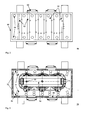
- Fig. 2 shows a second exemplary dry-type transformer in a plan view 60. It is a second closed container 66 and in the plan view, an upper roof wall 69 of the container 66 visible. This is pierced by a plurality of orifices of first heat exchanger tubes 62, which are arranged segmentally in a circle around three - not shown - located within the transformer windings. Only those cooling channels are brought out in an extension with a respective first heat exchanger tube 62 to the roof wall 69, which are not covered by a yoke of the transformer core, but as described in more detail in the next Fig.
- Valve means 68 are respectively arranged on two side walls of the container 66 at respective outlet openings, which ensure a minimum pressure within the container, in particular during operation, whereby a fan or compressor required to build up this pressure is not shown.
- Fig. 3 shows a third exemplary dry-type transformer in an open plan view 70.
- a transformer core 82 is visible with its upper yoke and three windings 76, which are each a hollow cylinder similar to a respective leg of the transformer and arranged around a respective winding axis 80.
- the cooling channels 74 which traverse them axially, are also visible, at least those which are not covered by the yoke of the transformer core 82.
Landscapes
- Engineering & Computer Science (AREA)
- Power Engineering (AREA)
- Transformer Cooling (AREA)
Priority Applications (2)
| Application Number | Priority Date | Filing Date | Title |
|---|---|---|---|
| EP09011194A EP2290662A1 (fr) | 2009-09-01 | 2009-09-01 | Transformateur de type sec |
| PCT/EP2010/005342 WO2011026603A1 (fr) | 2009-09-01 | 2010-08-31 | Transformateur à sec |
Applications Claiming Priority (1)
| Application Number | Priority Date | Filing Date | Title |
|---|---|---|---|
| EP09011194A EP2290662A1 (fr) | 2009-09-01 | 2009-09-01 | Transformateur de type sec |
Publications (1)
| Publication Number | Publication Date |
|---|---|
| EP2290662A1 true EP2290662A1 (fr) | 2011-03-02 |
Family
ID=41591695
Family Applications (1)
| Application Number | Title | Priority Date | Filing Date |
|---|---|---|---|
| EP09011194A Withdrawn EP2290662A1 (fr) | 2009-09-01 | 2009-09-01 | Transformateur de type sec |
Country Status (2)
| Country | Link |
|---|---|
| EP (1) | EP2290662A1 (fr) |
| WO (1) | WO2011026603A1 (fr) |
Cited By (3)
| Publication number | Priority date | Publication date | Assignee | Title |
|---|---|---|---|---|
| CN102842404A (zh) * | 2012-09-28 | 2012-12-26 | 丹东欣泰电气股份有限公司 | 一种海上风力发电用干式变压器装置 |
| CN106787435A (zh) * | 2017-01-10 | 2017-05-31 | 南通润雅机电科技有限公司 | 一种电梯发电装置 |
| CN111508696A (zh) * | 2020-03-13 | 2020-08-07 | 浙江城电电气有限公司 | 干式变压器 |
Families Citing this family (1)
| Publication number | Priority date | Publication date | Assignee | Title |
|---|---|---|---|---|
| DE102017102436B4 (de) * | 2017-02-08 | 2025-12-18 | Hitachi Energy Ltd | Trockentransformator mit Luftkühlung, Verfahren zur Kühlung und Verwendung eines Ring-Ventilators |
Citations (6)
| Publication number | Priority date | Publication date | Assignee | Title |
|---|---|---|---|---|
| US3201728A (en) * | 1962-08-23 | 1965-08-17 | Westinghouse Electric Corp | Evaporative cooled inductive apparatus having cast solid insulation with cooling ducts formed therein |
| US4472700A (en) * | 1981-12-18 | 1984-09-18 | Siemens Aktiengesellschaft | Transformer with copper windings, liquid insulation material and supply depot containing solid copper deactivator to prevent dissolution of the copper |
| US4485367A (en) * | 1981-12-25 | 1984-11-27 | Tokyo Shibaura Denki Kabushiki Kaisha | Cooling apparatus for a gas insulated transformer |
| EP0690464A1 (fr) * | 1994-07-01 | 1996-01-03 | MASCHINENFABRIK REINHAUSEN GmbH | Changeur de prises isolé à gaz |
| US20040070475A1 (en) * | 2001-04-04 | 2004-04-15 | Wolfgang Nick | Transformer with forced liquid coolant |
| US20070247266A1 (en) * | 2004-08-10 | 2007-10-25 | Yargole Arun D | Compact Dry Transformer |
-
2009
- 2009-09-01 EP EP09011194A patent/EP2290662A1/fr not_active Withdrawn
-
2010
- 2010-08-31 WO PCT/EP2010/005342 patent/WO2011026603A1/fr not_active Ceased
Patent Citations (6)
| Publication number | Priority date | Publication date | Assignee | Title |
|---|---|---|---|---|
| US3201728A (en) * | 1962-08-23 | 1965-08-17 | Westinghouse Electric Corp | Evaporative cooled inductive apparatus having cast solid insulation with cooling ducts formed therein |
| US4472700A (en) * | 1981-12-18 | 1984-09-18 | Siemens Aktiengesellschaft | Transformer with copper windings, liquid insulation material and supply depot containing solid copper deactivator to prevent dissolution of the copper |
| US4485367A (en) * | 1981-12-25 | 1984-11-27 | Tokyo Shibaura Denki Kabushiki Kaisha | Cooling apparatus for a gas insulated transformer |
| EP0690464A1 (fr) * | 1994-07-01 | 1996-01-03 | MASCHINENFABRIK REINHAUSEN GmbH | Changeur de prises isolé à gaz |
| US20040070475A1 (en) * | 2001-04-04 | 2004-04-15 | Wolfgang Nick | Transformer with forced liquid coolant |
| US20070247266A1 (en) * | 2004-08-10 | 2007-10-25 | Yargole Arun D | Compact Dry Transformer |
Cited By (5)
| Publication number | Priority date | Publication date | Assignee | Title |
|---|---|---|---|---|
| CN102842404A (zh) * | 2012-09-28 | 2012-12-26 | 丹东欣泰电气股份有限公司 | 一种海上风力发电用干式变压器装置 |
| CN102842404B (zh) * | 2012-09-28 | 2015-06-17 | 丹东欣泰电气股份有限公司 | 一种海上风力发电用干式变压器装置 |
| CN106787435A (zh) * | 2017-01-10 | 2017-05-31 | 南通润雅机电科技有限公司 | 一种电梯发电装置 |
| CN106787435B (zh) * | 2017-01-10 | 2019-02-12 | 南通润雅机电科技有限公司 | 一种电梯发电装置 |
| CN111508696A (zh) * | 2020-03-13 | 2020-08-07 | 浙江城电电气有限公司 | 干式变压器 |
Also Published As
| Publication number | Publication date |
|---|---|
| WO2011026603A1 (fr) | 2011-03-10 |
Similar Documents
| Publication | Publication Date | Title |
|---|---|---|
| EP0299908A1 (fr) | Machine électrique avec circuit de refroidissement fermé | |
| WO2008083838A1 (fr) | Bloc à semi-conducteurs destiné à être connecté à un enroulement de transformateur et ensemble transformateur ainsi obtenu | |
| DE202011110749U1 (de) | Elektrisches Bauteil mit wenigstens einer in einer Vergussmasse angeordneten elektrischen Verlustleistungsquelle und einer Kühleinrichtung und Kühlkanal | |
| EP2346052B1 (fr) | Boîtier pour une machine électrique | |
| DE2145748C3 (de) | Gasgekühlte dynamoelektrische Maschine mit einem Statorblechpaket, das abschnittsweise in entgegengesetzten Richtungen von Kühlgas durchströmte, radiale Kühlkanäle aufweist | |
| EP2290662A1 (fr) | Transformateur de type sec | |
| EP3494584B1 (fr) | Appareil électrique équipé de plusieurs unités de refroidissement | |
| EP3424059B1 (fr) | Transformateur équipé d'un module de refroidissement fixé par crochet | |
| EP2397781B1 (fr) | Echangeur thermique | |
| EP0993007B1 (fr) | Dispositif de transformateur avec circuit de refroidissement | |
| EP2795638B1 (fr) | Radiateur de refroidissement à refroidissement par liquide | |
| EP2793244A1 (fr) | Bobine de transformateur à sec et transformateur à sec | |
| EP3507559A1 (fr) | Intégration d'échangeur de chaleur | |
| EP1788320B1 (fr) | Echangeur de chaleur | |
| EP0805541A1 (fr) | Tête de bobine refroidie par un gaz pour une machine électrique | |
| EP3812677B1 (fr) | Radiateur destiné au refroidissement d'un transformateur ou d'une bobine d'inductance | |
| DE102007002878B3 (de) | Heizanordnung für Gebäude | |
| WO2019115130A1 (fr) | Élément de radiateur thermiquement isolé | |
| DE102010018086A1 (de) | Wärmeübertragungseinrichtung | |
| DE3837198A1 (de) | Elektroerhitzer zur thermischen behandlung von ein- oder mehrphasigen fluiden mit durch elektrischer widerstandsheizung direkt beheiztem rohr | |
| WO2003005535A2 (fr) | Dispositif de refroidissement d'un moteur electrique | |
| DE202016104805U1 (de) | Wärmetauscherintegration | |
| DE102016116276A1 (de) | Wärmetauscherintegration | |
| DE102023000271A1 (de) | Wärmetauscher und Vorrichtung zum Erwärmen von Luft und einem Medium | |
| WO2015197362A1 (fr) | Échangeur thermique |
Legal Events
| Date | Code | Title | Description |
|---|---|---|---|
| PUAI | Public reference made under article 153(3) epc to a published international application that has entered the european phase |
Free format text: ORIGINAL CODE: 0009012 |
|
| AK | Designated contracting states |
Kind code of ref document: A1 Designated state(s): AT BE BG CH CY CZ DE DK EE ES FI FR GB GR HR HU IE IS IT LI LT LU LV MC MK MT NL NO PL PT RO SE SI SK SM TR |
|
| AX | Request for extension of the european patent |
Extension state: AL BA RS |
|
| 17P | Request for examination filed |
Effective date: 20110315 |
|
| 17Q | First examination report despatched |
Effective date: 20110421 |
|
| STAA | Information on the status of an ep patent application or granted ep patent |
Free format text: STATUS: THE APPLICATION IS DEEMED TO BE WITHDRAWN |
|
| 18D | Application deemed to be withdrawn |
Effective date: 20130215 |