EP2290782B1 - Appareil d'alimentation électrique sans contact, appareil de réception d'alimentation électrique sans contact, procédé d'alimentation électrique sans contact, procédé de réception d'alimentation électrique sans contact et système d'alimentation électrique sans contact - Google Patents
Appareil d'alimentation électrique sans contact, appareil de réception d'alimentation électrique sans contact, procédé d'alimentation électrique sans contact, procédé de réception d'alimentation électrique sans contact et système d'alimentation électrique sans contact Download PDFInfo
- Publication number
- EP2290782B1 EP2290782B1 EP10007328.7A EP10007328A EP2290782B1 EP 2290782 B1 EP2290782 B1 EP 2290782B1 EP 10007328 A EP10007328 A EP 10007328A EP 2290782 B1 EP2290782 B1 EP 2290782B1
- Authority
- EP
- European Patent Office
- Prior art keywords
- electric power
- power feeding
- resonance
- noncontact
- circuit
- Prior art date
- Legal status (The legal status is an assumption and is not a legal conclusion. Google has not performed a legal analysis and makes no representation as to the accuracy of the status listed.)
- Active
Links
Images


Classifications
-
- H—ELECTRICITY
- H02—GENERATION; CONVERSION OR DISTRIBUTION OF ELECTRIC POWER
- H02J—ELECTRIC POWER NETWORKS; CIRCUIT ARRANGEMENTS OR SYSTEMS FOR SUPPLYING OR DISTRIBUTING ELECTRIC POWER; SYSTEMS FOR STORING ELECTRIC ENERGY
- H02J50/00—Circuit arrangements or systems for wireless supply or distribution of electric power
- H02J50/10—Circuit arrangements or systems for wireless supply or distribution of electric power using inductive coupling
- H02J50/12—Circuit arrangements or systems for wireless supply or distribution of electric power using inductive coupling of the resonant type
Definitions
- the present invention relates to noncontact electric power feeding apparatus and method for feeding an electric power by using a resonance such as a magnetic field resonance or an electric field resonance, noncontact electric power receiving apparatus and method for receiving the electric power by using the resonance such as the magnetic field resonance or the electric field resonance, and a noncontact electric power feeding system for feeding the electric power by using the resonance such as the magnetic field resonance or the electric field resonance.
- An electromagnetic induction system and a magnetic field resonance system are each known as a technique for enabling an electric energy to be transmitted in a noncontact style. Also, the electromagnetic induction system and the magnetic field resonance system are different in various respects from each other. In recent years, the energy transmission using the magnetic field resonance system attracts attention.
- FIG. 8 is a conceptual diagram, partly in circuit, showing a basic configuration of a noncontact electric power feeding system using the magnetic field resonance system.
- the noncontact electric power feeding system using magnetic field resonance system is composed of an electric power feeding side (electric power feeding apparatus) 100, and an electric power receiving side (electric power receiving apparatus) 200.
- the electric power feeding side 100 includes an A.C. power source 101 and a resonance element 102.
- the A.C. power source 101 generates an A.C. electric power (A.C. current) having the same self-resonance frequency as that of the resonance element 102 and supplies the A.C. electric power thus generated to the resonance element 102.
- the electric power receiving side 200 is composed of a resonance element 201 and a load circuit 202.
- the resonance element 101 of the electric power feeding side 100 and the resonance element 201 of the electric power receiving side 200 are identical in self-resonance frequency to each other, and are coupled to each other through magnetic field coupling.
- the A.C. electric power generated by the A.C. power source 102 of the electric power feeding side 100 is supplied to the resonance element 102, thereby generating the magnetic field in the resonance element 102. Also, the magnetic field coupling is caused between the resonance element 102 of the electric power feeding side 100, and the resonance element 201 of the electric power receiving side 200 to induce the A.C. electric power in the resonance element 201 of the electric power receiving side 200. The A.C. electric power thus induced is supplied to the load circuit 202.
- an unmodulated sine wave having a central frequency f 0 is used as the A.C. power. Since this unmodulated sine wave is unmodulated one, an occupied frequency bandwidth is narrow (ideally 0 (zero) Hz) .
- a frequency band necessary for the resonance coil through which the unmodulated sine wave is transmitted has to be as narrow as about several hertz.
- a Q value is large.
- the Q value represents the sharpness of the peak of the resonance in the resonance circuit, and thus when the peak of the resonance becomes sharp, it is possible to increase the transmission efficiency of the A.C. electric power.
- the Q value of the resonance element 102 is reduced due to the influence of circuit impedance.
- the resonance element 201 is directly connected to the A.C. load circuit 202 on the electric power receiving side 200 as well, the Q value of the resonance element 201 is reduced due to the influence of circuit impedance.
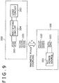
- FIG. 9 is a block diagram showing an example of a configuration of a noncontact electric power feeding system, using a magnetic field resonance system, which is configured in order to prevent both the reflection of the electric power, and the reduction of the Q value by providing excitation elements in both the electric power feeding side 100 and the electric power receiving side 200, respectively.
- the electric power feeding side 100 has a configuration such that an excitation element 103 is provided between the A.C. power source 101 and the resonance element 102.
- the electric power receiving side 200 has a configuration such that an excitation element 203 and a rectifying circuit 204 are provided between the resonance element 201 and the load circuit 202.
- the electric power feeding side 100 for example, is realized in the form of a charging apparatus or the like.
- the electric power receiving side 200 for example, is realized in the form of a mobile electronic apparatus such as a mobile-phone unit.
- the inside of the electric power feeding side 100 is configured in such a way that the excitation element 103 is connected to the A.C. power source 101, and the excitation element 103 and the resonance element 102 are strongly coupled to each other through the electromagnetic induction.
- the inside of the electric power receiving apparatus 200 is configured in such a way that the resonance element 201 and the excitation element 203 are strongly coupled to each other through the electromagnetic induction, the excitation element 203 is connected to the rectifying circuit 204, and the rectifying circuit 204 and the load circuit 202 are connected to each other.
- the resonance element 102 of the electric power feeding side 100, and the resonance element 201 of the electric power receiving side 200 show a magnetic field resonance relationship. As a result, a coupling amount becomes maximum, and a loss becomes minimum.
- an A.C. electric power (A.C. current) having a predetermined frequency is supplied from the A.C. power source 101 to the excitation element 103, which results in that an A.C. electric power is induced in the resonance element 102 through the electromagnetic induction.
- a frequency of the A.C. electric power generated in the A.C. power source 101 is set as being identical to each of a self-resonance frequency of the resonance element 102 of the electric power supply source, and a self-resonance frequency of the resonance element 201 of the electric power supply destination.
- the resonance element 102 of the electric power feeding side 100, and the resonance element 201 of the electric power receiving side 200 are disposed so as to show the magnetic field resonance relationship.
- the A.C. electric power is supplied from the resonance element 102 to the resonance element 201 at a resonance frequency in a noncontact style.
- the A.C. electric power supplied from the resonance element 102 of the electric power feeding side 100 is received by the resonance element 201.
- the A.C. electric power from the resonance element 201 is supplied to the rectifying circuit 204 via the excitation element 203 through the electromagnetic induction, and is then converted into a D.C. electric power (D.C. current) in the rectifying circuit 204 to be supplied to each of the various kinds of load circuits 202.
- D.C. electric power D.C. current
- the D.C. electric power is supplied from the electric power feeding side 100 to the electric power receiving side 200 in the noncontact style. It is noted that the D.C. electric power outputted from the rectifying circuit 204, for example, is supplied to a charging circuit as the load circuit 202 to which a battery is connected, thereby being used to charge the battery with the electricity.
- the noncontact electric power feeding system concerned has a relationship, as shown in FIG. 10 , between the frequency of the A.C. power source and the coupling amount.
- the coupling amount does not become large.
- the coupling amount becomes maximum only at a specific frequency at which a magnetic field resonance phenomenon is caused. That is to say, the magnetic field resonance allows the frequency property of the coupling amount to show a frequency selectivity property.
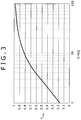
- the noncontact electric power feeding system concerned has a relationship, as shown in FIG. 11 , between a distance between the resonance elements 102 and 201, and the coupling amount. As can be seen from FIG. 12 , the coupling amount is reduced as the distance between the resonance elements 102 and 201 becomes longer.
- the coupling amount does not become large just because the distance between the resonance elements 102 and 201 is short.
- the distance at which the coupling amount becomes maximum exists at a certain resonance frequency.
- the noncontact electric power feeding system has a relationship, as shown in FIG. 12 , between the resonance frequency and the inter-resonance element distance at which the maximum coupling amount is obtained. That is to say, it is understood from FIG. 12 that when the resonance frequency is low, the resonance element interval is wide. In addition, it is also understood from FIG. 12 that when the resonance frequency is high, the maximum coupling amount can be obtained by narrowing the resonance element interval.
- the electric power feeding side and the electric power receiving side need to have a magnetic flux in common.
- the electric power feeding source and the electric power feeding destination need to be disposed close proximity to each other, and thus the axis alignment for the coupling between the electric power feeding source and the electric power feeding destination becomes also important.
- the noncontact electric power feeding system using the magnetic field resonance phenomenon has an advantage that from the principles called the magnetic field resonance phenomenon, the electric power can be transmitted at a longer distance than that in the case of the noncontact electric power feeding system using the electromagnetic induction system, and even when the axis alignment is slightly poor, the electric power transmission efficiency is not reduced so much.
- US Patent Application Publication No. 2007/0222542 discloses a technique about an electric power transmission system using the magnetic field resonance system as described above.
- JP 11 188113 A discloses a system provided with a variable cpacitor on both the feeding side and the receiving side.
- US 2004/095291 A1 discloses an electromagnetic coupling characteristic adjustment method for adjusting an electromagnetic coupling characteristic between a reader/writer device and an IC card which are used in a non-contact communication system.
- JP 2001 238372 A discloses a noncontact IC card system including an impedance matching circuit, connected with an antenna coil on a transmitter or a receiver and detects transmission and receiving conditions of power simultaneously, determines whether impedance matching is satisfied, and according to the result, switches the matching conditions automatically.
- WO 2009/089146 A1 discloses a method and an apparatus according to an embodiment of the invention includes a transmitter and/or a receiver for transferring power wirelessly.
- the power transfer between the transmitter and the receiver can occur by electric field.
- the reason for this is because when the distance between the resonance element 102 of the electric power feeding side 100, and the resonance element 201 of the electric power receiving side 200 is too short to provide the tight coupling state, the resonance frequency is separated into two parts to provide double-humped resonance characteristics, and thus the electric power transmission efficiency at the central frequency becomes worse.
- the present invention has been made in order to solve the problems described above, and it is therefore desirable to provide noncontact electric power feeding apparatus and method, noncontact electric power receiving apparatus and method, and a noncontact electric power feeding system in each of which even in the case where a distance between an electric power feeding side and an electric power receiving side becomes short to provide a tight coupling state when an electric power is fed or received in a noncontact style by using a resonance system, the electric power transmission efficiency can be highly maintained.
- the impedance is properly matched, thereby making it possible to highly maintain the transmission efficiency.
- noncontact electric power feeding apparatus and method noncontact electric power receiving apparatus and method
- a noncontact electric power feeding system according to embodiments of the present invention will be described in detail with reference to the accompanying drawings.
- resonance systems such as the magnetic field resonance system, the electric field resonance system, and the electromagnetic resonance system, hereinafter, a description will be given by exemplifying the case where the magnetic field resonance system is used.
- FIG. 1 is a block diagram, partly in circuit, showing a configuration of the noncontact electric power feeding system using the magnetic field resonance system according to an embodiment of the present invention.
- the noncontact electric power feeding system using the magnetic field resonance system according to the embodiment of the present invention is composed of an electric power feeding side (electric power feeding source) 1, and an electric power receiving side (electric power feeding destination) 2.
- the electric power feeding side 1 feeds the electric power to another electronic apparatus in a noncontact style by using the magnetic field resonance system, and realizes a function as a noncontact electric power feeding apparatus.
- the electric power feeding side 1 for example, is realized in the form of an electronic apparatus such as a charging apparatus (cradle).
- the electric power receiving side 2 receives the electric power from the electric power feeding side 1 in a noncontact style in the embodiment, and uses the electric power for driving of an auto-load circuit, and realizes a function of a noncontact electric power receiving apparatus.
- the electric power receiving side 2 is realized in the form of any, of various kinds of electronic apparatuses, which is required to receive the electric power from the outside in the noncontact style and which is typified by a mobile-phone unit.
- the electric power feeding side 1 includes an A.C. power source 11, an automatic matching box 12, an excitation element 13, and a resonance element 14 for the electric power feeding.
- each of the excitation element 13, and the resonance element 14 for the electric power feeding is constructed in the form of an air core coil.
- a function as an impedance converter 15 is realized by the automatic matching box 12 and the excitation element 13.
- the excitation element 13 obtains the impedance matching between the A.C. power source 11 and the resonance element 14 for the electric power feeding, thereby preventing reflection of the electric power.
- the excitation element 13 realizes a function of highly maintaining a Q value of the resonance element 14 by fixedly setting the impedance of the resonance element 14 for the electric power feeding as a suitable value.
- a conversion rate of the impedance using the excitation element 13 is fixed.
- the impedance needs to be controlled so as to match the impedance which is changed in accordance with a coupling coefficient, k, which is changed depending on the transmission distance of the electric power.
- the automatic matching box 12 realizes a function of variably adjusting an impedance of a resonance circuit having the resonance element 14 for the electric power feeding in accordance with the coupling coefficient, k, which is changed depending on the transmission distance of the electric power. In such a manner, the automatic matching box 12 has the function of variably controlling the impedance conversion rate.
- the electric power receiving side 2 includes a resonance element 21 for electric power reception, an excitation element 22, an automatic matching box 23, a rectifying circuit 24, and a load circuit 25.
- each of the resonance element 21 for electric power reception and the excitation element 22 is constructed in the form of an air core coil.
- a function as an impedance converter 26 is realized by the excitation element 22 and the automatic matching box 23.
- the excitation element 22 obtains the impedance matching between the resonance element 21 for electric power reception and the rectifying circuit 23, thereby preventing the reflection of the electric power.
- the excitation element 22 realizes a function of highly maintaining the Q value of the resonance element 21 for electric power reception by fixedly maintaining the impedance of the resonance element 21.
- a conversion rate of the impedance using the excitation element 22 is fixed. For this reason, in the electric power receiving side 2 as well, the impedance needs to be controlled so as to match the impedance which is changed in accordance with the coupling coefficient, k, which is changed depending on the transmission distance of the electric power.
- the automatic matching box 23 realizes a function of variably adjusting an impedance of a resonance circuit having the resonance element 21 for the electric power reception in accordance with the coupling coefficient, k, which is changed depending on the transmission distance of the electric power. In such a manner, the automatic matching box 23 has the function of variably controlling the impedance conversion rate.
- the resonance element 14 of the electric power feeding side 1, and the resonance element 21 of the electric power receiving side 2 are identical in self-resonance frequency to each other, and are coupled to each other through the magnetic field coupling. Also, an input/output impedance between the resonance element 14 and the resonance element 21 depends on the coupling coefficient k between the resonance elements and the Q value of the resonance element. Thus, there is shown a relationship that the input impedance becomes small as both the coupling coefficient k and the Q value are larger.
- the A.C. power source 11 of the electric power feeding side 1 generates an A.C. electric power (A.C. current) having the same frequency or approximately the same frequency as the self-resonance frequency of the resonance element 14 of the electric power feeding side 1, and supplies the A.C. electric power thus generated to the excitation element 13 through the automatic matching box 12.
- A.C. power source 11 of the electric power feeding side 1 for example, includes a Colpitts oscillating circuit, a Hartley oscillating circuit or the like.
- the excitation element 13 of the electric power feeding side 1 is an element which is excited by the A.C. electric power supplied thereto from the A.C. power source 11, thereby supplying the A.C. electric power therefrom to the resonance element 14 for the electric power feeding.
- the excitation element 13 which receives the A.C. electric power supplied thereto from the A.C. power source 11, and the resonance element 14 for the electric power feeding are strongly coupled to each other through the electromagnetic induction. To this end, the A.C. electric power from the A.C. power source 11 is supplied to the resonance element 14 for the electric power feeding through the excitation element 13.
- the resonance element 14 for the electric power feeding generates the magnetic field in accordance with the A.C. electric power supplied thereto from the excitation element 13.
- the resonance element 14 for the electric power feeding includes an inductor L and a capacitor C. The strength of the magnetic field of the resonance element 14 for the electric power feeding becomes highest at a resonance frequency.
- the resonance frequency f 01 of the resonance element 14 for the electric power feeding depends on the inductance L 1 and the capacitance C 1 each of which the resonance element 14 for the electric power feeding has.
- a line capacitor of the resonance element 14 for the electric power feeding plays a part of the capacitor.
- the resonance element 14 for the electric power feeding generates the magnetic field in an axial direction of the coil.
- the resonance element 21 for the electric power reception of the electric power receiving side 2 is an element which receives the A.C. electric power supplied thereto from the electric power feeding side 1 in accordance with the magnetic field coupling based on the magnetic field resonance.
- the resonance element 21 for the electric power reception has the same resonance frequency or approximately the same resonance frequency as that of the resonance element 14 for the electric power feeding of the electric power feeding side 1.
- the resonance element 21 for the electric power reception of the electric power receiving side 2 is constructed in the form of the air core coil, a line capacitor plays a part of a capacitor. Also, as shown in FIG. 1 , the resonance element 21 for the electric power reception of the electric power receiving side 2 is coupled to the resonance element 14 for the electric power feeding of the electric power feeding side 1 through the magnetic field resonance.
- the A.C. electric power is supplied from the resonance element 14 for the electric power feeding of the electric power feeding side 1 to the resonance element 21 for the electric power reception of the electric power receiving side 2 at the resonance frequency in the noncontact style through the magnetic field resonance.
- the resonance element 21 for the electric power reception and the excitation element 22 are coupled to each other through the electromagnetic induction.
- the A.C. electric power is supplied from the resonance element 21 for the electric power reception to the rectifying circuit 24 through the excitation element 22 and the automatic matching box 23.
- the rectifying circuit 24 creates a D.C. electric power which will be supplied to the load circuit 25 in a subsequent stage from the A.C. electric power supplied thereto through the excitation element 22 and the automatic matching box 23, and then supplies the D.C. electric power thus created to the load circuit 25.
- the load circuit 25, for example, is any of various kinds of circuit portions such as a charging circuit having a battery.
- the electric power can be fed from the electric power feeding side 1 to the electric power receiving side 2 in the noncontact style.
- the Q value is highly maintained by suitably holding the impedance of the resonance circuit having the resonance element 14 for the electric power feeding, and the transmission efficiency of the electric power is held at the high efficiency.
- the Q value is highly maintained by suitably holding the impedance of the resonance circuit having the resonance element 21 for the electric power reception, and the transmission efficiency of the electric power is held at the high efficiency.
- the resonance frequency is separated into two parts to provide the double-humped resonance characteristics. As a result, the transmission efficiency at the resonance frequency becomes worse.
- the automatic matching box 12 can adjust adaptively the impedance in accordance with the coupling coefficient k which is changed depending on the transmission distance.
- the automatic matching box 23 can adjust adaptively the impedance in accordance with the coupling coefficient k which is changed depending on the transmission distance.
- the resonance element 14 for the electric power feeding of the electric power feeding side 1, and the resonance element 21 for the electric power reception of the electric power receiving side 2 are identical in self-resonance frequency to each other, and are coupled to each other through the magnetic field coupling. Also, the transmission efficiency between the resonance element 14 for the electric power feeding and the resonance element 21 for the electric power reception depends on both the coupling coefficient k between the resonance element 14 for the electric power feeding and the resonance element 21 for the electric power reception, and the Q values of the resonance element 14 for the electric power feeding and the resonance element 21 for the electric power reception. Thus, the transmission efficiency of the electric power becomes high as both the coupling coefficient k and the Q value are larger.
- the coupling coefficient k depends on the distance between the resonance elements, and each of the sizes of the resonance elements.
- the coupling becomes strong and the high efficiency is obtained as each of the sizes of the resonance elements is larger and the distance between the resonance elements is shorter.
- the coupling coefficient k is changed in accordance with the distance between the resonance elements.
- the impedance of the resonance circuit having the resonance element 14 for the electric power feeding can be adjusted in accordance with the coupling coefficient k between the electric power feeding side 1 and the electric power receiving side 2.
- the impedance of the resonance circuit having the resonance element 21 for the electric power reception can be adjusted in accordance with the coupling coefficient k between the electric power feeding side 1 and the electric power receiving side 2.
- the impedance of the resonance circuit having the resonance element 14 for the electric power feeding of the electric power feeding side 1 can be both adjusted in accordance with the coupling coefficient k between the electric power feeding side 1 and the electric power receiving side 2.
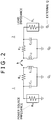
- FIG. 2 is an equivalent circuit diagram of the noncontact electric power feeding system having the basic configuration in which the electric power feeding side 1 is composed of the A.C. power source 11 and the resonance element 14 for the electric power feeding, and the electric power receiving side 2 is composed of the resonance element 21 for the electric power reception, and the load circuit 25 similarly to the case of the noncontact electric power feeding system using the magnetic field resonance system shown in FIG. 8 .
- the A.C. power source 11 of the electric power feeding side 1 can be equivalently expressed in the form of an A.C. power source having an impedance R s .
- the resonance element 14 for the electric power feeding of the electric power feeding side 1 can be equivalently expressed in the form of a resonance circuit having an inductor L 1 , a capacitor C 1 , and a resistor R 1 .
- the resonance element 21 of the electric power receiving side 2 can be equivalently expressed in the form of a resonance circuit having an inductor L 2 , a capacitor C 2 , and a resistor R 2 .
- the load circuit 25 of the electric power receiving side 2 can be equivalently expressed in the form of a load having an impedance R L .
- the resonance frequency f 01 of the resonance element 14 for the electric power feeding of the electric power feeding side 1 can be expressed by Expression (1) described above.
- the resonance frequency f 02 of the resonance element 21 for the electric power reception of the electric power reception side 2 can be expressed by Expression (2) described above.
- the coupling coefficient between the resonance element 14 for the electric power feeding of the electric power feeding side 1, and the resonance element 21 for the electric power reception of the electric power reception side 2 is designated by reference symbol k.
- a Q value of the circuit composed of the resonance element (resonance circuit) 14 and the resonance element (resonance circuit) 21 is designated by reference symbol Q.
- a multiplication value (k ⁇ Q) of the coupling coefficient k and the Q value is expressed by reference symbol S.
- FIG. 4 shows transmission characteristics in the case where when this state is held, each of the power source impedance R S and the load impedance R L is fixed to 3,000 ( ⁇ ), and the coupling coefficient, k, is changed to 0.01, 0.04, 0.07, and 0.21 in order.
- FIG. 5 shows the transmission characteristics of the electric power when in order to cope with such a situation, the coupling coefficient k is changed to 0.01, 0.04, 0.07, and 0.1 in order in the manner as described above, and each of the power source impedance R S and the load impedance R L is made variable in accordance with Expression (7).
- each of the power source impedance R S and the load impedance R L is fixed.
- the electric power feeding side 1 is provided with the automatic matching box 12 for the impedance adjustment and the electric power receiving side 2 is provided with the automatic matching box 23 for the impedance adjustment.
- the Q value of the resonance element 14 for the electric power feeding is highly maintained by adjusting the impedance of the electric power feeding side 1 in accordance with the magnitude of the coupling coefficient k and thus the transmission efficiency of the electric power is highly held.
- the Q value of the resonance element 21 for the electric power reception is highly maintained by adjusting the impedance of the electric power receiving side 2 in accordance with the magnitude of the coupling coefficient k and thus the transmission efficiency of the electric power is highly held.
- the impedances of the electric power feeding side 1 and the electric power receiving side 2 are suitably controlled in accordance with the magnitude of the coupling coefficient, k.
- the transmission efficiency of the electric power is prevented from being reduced even at the central frequency on a steady basis.
- the reduction of the impedance means that the reflected electric power is increased.
- the reflected electric power is detected instead of directly detecting the change of the coupling coefficient k and the impedance is directly adjusted so that the reflected electric power disappears.
- FIG. 6 is a block diagram showing the configuration of the automatic matching box 12 of the electric power feeding side 1.
- the automatic matching box 12 of the electric power feeding side 1 is composed of a directional coupler 121, an Analog/Digital (A/D) conversion circuit 122, a microcomputer (hereinafter referred to as "a micom" for short) 123, and an LC variable circuit 124.
- A/D Analog/Digital
- micom microcomputer
- the directional coupler 121 is a device of three ports (unidirectional coupler) in the case of FIG. 6 .
- the directional coupler 121 detects the reflected electric power which is changed in accordance with the coupling coefficient k as described above, and supplies the reflected electric power thus detected to the A/D converter 122.
- the A/D converter 122 converts the reflected electric power supplied thereto from the directional coupler 121 into a digital signal and supplies the resulting digital signal to the micom 123.
- the micom 123 produces a control signal in accordance with which the LC variable circuit 124 is controlled based on the magnitude of the reflected electric power from the A/D converter 122, and supplies the control signal thus produced to the LC variable circuit 124.
- the LC variable circuit 124 includes a variable inductor and a variable capacitor in the case of the automatic matching box 12 shown in FIG. 6 .
- the LC variable circuit 124 controls both the variable inductor and the variable capacitor in accordance with the control signal supplied thereto from the micom 123, thereby adjusting the impedance of the electric power feeding side 1.
- the inductance value of the variable inductor, and the capacitance value of the variable capacitor are adjusted to adjust the impedance of the electric power feeding side 1, thereby preventing the double-humped resonance characteristics from being provided as previously described with reference to FIG. 5 .
- the inductance value of the variable inductor, and the capacitance value of the variable capacitor in the LC variable circuit 124 are adjusted so as to reduce the magnitude of the reflected electric power to zero.
- the inductance value of the inductor in the resonance circuit of the electric power feeding side 1 is preferably adjusted.
- the double-humped resonance characteristics are avoided on the electric power feeding side 1, thereby preventing the transfer characteristics of the electric power from being deteriorated at the central frequency.
- the automatic matching box 23 of the electric power receiving side 2 is also basically configured similarly to the case of the automatic matching box 12 of the electric power feeding side 1 shown in FIG. 6 .
- FIG. 7 is a block diagram showing the configuration of the automatic matching box 23 of the electric power receiving side 2.
- the automatic matching box 23 of the electric power receiving side 2 is composed of a directional coupler 231, an A/D converter 232, a micom 233, and an LC variable circuit 234.
- the directional coupler 231 is a device of three ports (unidirectional coupler) similarly to the case of the directional coupler 121 of the electric power feeding side 1 described above.
- the directional coupler 231 detects the reflected electric power which is changed in accordance with the coupling coefficient k and supplies the reflected electric power thus detected to the A/D converter 232.
- the A/D converter 232 converts the reflected electric power supplied thereto from the directional coupler 231 into a digital signal and supplies the resulting digital signal to the micom 233.
- the micom 233 produces a control signal in accordance with which the LC variable circuit 234 is controlled based on the magnitude of the reflected electric power from the A/D converter 232, and supplies the control signal thus produced to the LC variable circuit 234.
- the LC variable circuit 234 includes a variable inductor and a variable capacitor similarly to the case of the LC variable circuit 124 of the electric power feeding side 1.
- the LC variable circuit 234 controls both the variable inductor and the variable capacitor in accordance with the control signal supplied thereto from the micom 233, thereby adjusting the impedance of the electric power receiving side 2.
- the inductance value of the variable inductor, and the capacitance value of the variable capacitor are adjusted to adjust the impedance of the electric power feeding side 1, thereby preventing the double-humped resonance characteristics from being provided as previously described with reference to FIG. 5 .
- the inductance value of the variable inductor, and the capacitance value of the variable capacitor in the LC variable circuit 234 are adjusted so as to reduce the magnitude of the reflected electric power to zero.
- the inductance value of the inductor in the resonance circuit of the electric power receiving side 2 is properly adjusted.
- the double-humped resonance characteristics are avoided on the electric power receiving side 2 as well, thereby preventing the transfer characteristics of the electric power from being deteriorated at the central frequency.
- the automatic matching box 12 shown in FIG. 6 , and the automatic matching box 23 shown in FIG. 7 are both used, whereby the impedance matching can be suitably carried out in each of the electric power feeding side 1 and the electric power receiving side 2.
- each of the automatic matching boxes 12 and 23 can be realized in the form of either a low-pass filter or a high-pass filter which is composed of an L type circuit (L match), a T type circuit (T match) or a ⁇ type circuit ( ⁇ match) .
- the LC variable circuit 124 is used in the automatic matching box 12 shown in FIG. 6 .
- the present invention is by no means limited thereto. That is to say, an adjusting circuit using one of the variable inductor and the variable capacitor may be used in the automatic matching box 12 instead of using the LC variable circuit 124 as long as the impedance of the resonance circuit can be suitably adjusted.
- the LC variable circuit 234 is used in the automatic matching box 23 shown in FIG. 7 .
- the present invention is by no means limited thereto. That is to say, an adjusting circuit using one of the variable inductor and the variable capacitor may be used in the automatic matching box 23 instead of using the LC variable circuit 234 as long as the impedance of the resonance circuit can be suitably adjusted.
- the impedance of the electric power receiving side 2 may be adjusted so that the magnitudes of the A.C. electric power and the D.C. electric power become the predetermined magnitudes, respectively.
- a detector for detecting the magnitude of the A.C. electric power is provided in the preceding stage of the rectifying circuit 24 instead of using the directional coupler 231. Also, a detection output from the detector is fed back to the A/D converter 232 of the automatic matching box 23.
- the A/D converter 232 converts the magnitude of the A.C. electric power into a digital signal, and supplies the resulting digital signal to the micom 233, and the micom 233 adjusts the impedance by controlling the LC variable circuit 234, thereby adjusting the magnitude of the A.C. electric power to the desired magnitude.
- a detector for detecting the magnitude of the D.C. electric power is provided in the subsequent stage of the rectifying circuit 24 instead of using the directional coupler 231. Also, a detection output from the detector is fed back to the A/D converter 232 of the automatic matching box 23.
- the A/D converter 232 converts the magnitude of the D.C. electric power into a digital signal, and supplies the resulting digital signal to the micom 233, and the micom 233 adjusts the impedance by controlling the LC variable circuit 234, thereby adjusting the magnitude of the D.C. electric power to the desired magnitude.
- the double-humped resonance characteristics are not provided, but the single peak resonance characteristics can be provided, and thus the transmission characteristics can be made to have the boarder band. Therefore, even when the electric power is not fed or received, but the communication is carried out, the present invention can be applied thereto, and thus the data can be precisely transmitted at a high speed even in a near distance.
- the noncontact electric power feeding system composed of the electric power feeding side (noncontact electric power feeding apparatus) 1, and the electric power receiving side (noncontact electric power receiving apparatus) 2 is configured in accordance with the application of the noncontact electric power feeding system according to an embodiment of the present invention.
- the noncontact electric power feeding apparatus includes: the resonance element 14 for supplying the A.C. electric power in the noncontact style in accordance with the resonance; the A.C. power source 11 for generating the A.C. electric power to be supplied to the resonance element; and the automatic matching box 12 provided between the A.C. power source 11 and the resonance element 14 for variably controlling the impedance in accordance with the coupling coefficient, k, between the noncontact electric power feeding apparatus and the electric power receiving side 2 of the A.C. electric power.
- the noncontact electric power receiving apparatus includes: the resonance element 21 for receiving the A.C. electric power in the noncontact style in accordance with the resonance from the resonance element 14 of the electric power feeding side 1; the rectifying circuit 24 for creating the D.C. electric power from the A.C. electric power received through the resonance element 21 to output the D.C. electric power thus created; and the automatic matching box 23 provided between the resonance element 21 and the rectifying circuit 24 for variably controlling the impedance in accordance with the magnitude of the coupling coefficient, k, between the electric power receiving side 2 and the electric power feeding side 1 of the A.C. electric power.
- the electric power feeding method in the electric power feeding side 1 described with reference to FIGS. 1 to 6 is a noncontact electric power feeding method of the present invention. That is to say, the noncontact electric power feeding method according to yet another embodiment of the present invention includes the step of: variably controlling the impedance in accordance with the coupling coefficient k between the A.C. power source 11 for generating the A.C. electric power, and the electric power receiving side 2 of the A.C. electric power between the A.C. power source 11 and the resonance element 14 for supplying the A.C. electric power from the A.C. power source 11 to another electronic apparatus in the noncontact style.
- the noncontact electric power feeding method according to the yet another embodiment of the present invention is realized in the apparatus having the configuration shown in FIGS. 1 and 6 .
- the electric power receiving method in the electric power receiving side 2 described with reference to FIGS. 1 to 5 and FIG. 7 is a noncontact electric power receiving method of the present invention. That is to say, the noncontact electric power receiving method according to a further embodiment of the present invention includes the step of: variably controlling the impedance in accordance with the magnitude of the coupling coefficient k between the electric power feeding side 1 of the A.C. electric power and the electric power receiving side 2 of the A.C. electric power between the resonance element 21 for receiving the A.C. electric power in the noncontact style in accordance with the resonance from the resonance element 14 of the electric power feeding side 1, and the rectifying circuit 24 for creating the D.C. electric power from the A.C. electric power received through the resonance element 21 to output the D.C. electric power thus created.
- the noncontact electric power receiving method according to the further embodiment of the present invention is realized in the apparatus having the configuration shown in FIGS. 1 and 7 .
- the resonance element 14 for the electric power feeding of the electric power feeding side 1 shown in FIG. 1 realizes the function as the resonance element in the noncontact electric power feeding apparatus in the another embodiment of the present invention.
- the A.C. power source 11 of the electric power feeding side 1 shown in FIG. 1 realizes the A.C. power source portion in the noncontact electric power feeding apparatus in the another embodiment of the present invention.
- the automatic matching box 12 of the electric power feeding side 1 realizes the impedance adjusting means in the noncontact electric power feeding apparatus in the another embodiment of the present invention.
- the LC variable circuit 124 shown in FIG. 6 realizes the adjusting means
- the directional coupler 121 shown in FIG. 6 realizes the detecting means
- the micom 123 shown in FIG. 6 realizes the control means.
- the resonance element 21 for the electric power reception of the electric power receiving side 2 shown in FIG. 1 realizes the function as the resonance element in the noncontact electric power receiving apparatus in the still another embodiment of the present invention
- the rectifying circuit 24 of the electric power receiving side 2 realizes the rectifying circuit in the noncontact electric power receiving apparatus in the still another embodiment of the present invention
- the automatic matching box 23 of the electric power receiving side 2 realizes the impedance adjusting means in the noncontact electric power receiving apparatus in the still another embodiment of the present invention.
- the LC variable circuit 234 shown in FIG. 7 realizes impedance adjusting means
- the directional coupler 231 shown in FIG. 7 realizes detecting means
- the micom 233 shown in FIG. 7 realizes control means.
- the present invention is by no means limited thereto. That is to say, the present invention is suitably applied to various kinds of electronic apparatuses, each required to receive the electric power from the outside, such as a portable music player, a portable game machine, a digital still camera, a digital video camera, and an electronic databook, especially, a portable electronic apparatus which is carried to be utilized.
- the present invention can also be applied to the case where information is transmitted between near apparatuses by using the same system or the case where both the information and the electric power are transmitted in addition to the case where the electric power is fed or received in the manner described above.
- the present invention can also be similarly applied not only to the case where the electric power is supplied in the noncontact style by using the magnetic field resonance system, but also to the case where the electric power is supplied in the noncontact style by using either the electric field resonance system or the electromagnetic resonance system.
Landscapes
- Engineering & Computer Science (AREA)
- Computer Networks & Wireless Communication (AREA)
- Power Engineering (AREA)
- Charge And Discharge Circuits For Batteries Or The Like (AREA)
- Current-Collector Devices For Electrically Propelled Vehicles (AREA)
- Electric Propulsion And Braking For Vehicles (AREA)
Claims (4)
- Appareil d'alimentation en énergie électrique sans contact (1), comprenant :un élément de résonance (14) pour fournir une énergie électrique à courant alternatif dans un style sans contact selon une résonance;une partie de source d'énergie à courant alternatif (11) configurée pour générer une énergie électrique à courant alternatif à fournir audit élément de résonance (14); etun boîtier d'adaptation automatique (12) prévu entre ladite partie de source d'alimentation à courant alternatif (11) et ledit élément de résonance (14) caractérisé par,ledit boîtier d'adaptation automatique (12) étant composé d'un coupleur directionnel (121), d'un circuit de conversion analogique/numérique (A/N) (122), d'un micro-ordinateur (123) et d'un circuit variable LC (124), dans lequel :ledit coupleur directionnel (121) est un dispositif à trois ports qui est configuré pour détecter une énergie électrique réfléchie qui est modifiée en fonction d'un coefficient de couplage (k) entre ledit appareil d'alimentation en énergie électrique sans contact (1) et une destination d'alimentation en énergie électrique, et pour fournir l'énergie électrique réfléchie ainsi détectée au circuit de conversion A/N (122),ledit circuit de conversion A/N (122) est configuré pour convertir l'énergie électrique réfléchie qui lui est fournie par le coupleur directionnel (121) en un signal numérique et pour fournir le signal numérique résultant au micro-ordinateur (123), qui est configuré pour produire un signal de commande en fonction duquel le circuit variable LC (124) est commandé sur la base de l'amplitude de l'énergie électrique réfléchie du circuit de conversion A/N (122), et pour fournir le signal de commande ainsi produit au circuit variable LC (124), etledit circuit variable LC (124) comprend un inducteur variable et un condensateur variable et est configuré pour commander l'inducteur variable et le condensateur variable en fonction du signal de commande qui lui est fourni par le micro-ordinateur (123) de manière à réduire à zéro l'amplitude de l'énergie électrique réfléchie.
- Appareil de réception d'énergie électrique sans contact, comprenant :un élément de résonance (21) pour recevoir une énergie électrique à courant alternatif dans un style sans contact selon une résonance à partir d'un élément de résonance (14) d'une source d'alimentation en énergie électrique;un circuit redresseur (24) pour créer une énergie électrique à courant continu à partir de l'énergie électrique à courant alternatif reçue par l'intermédiaire dudit élément de résonance afin de délivrer l'énergie électrique à courant continu ainsi créée; etun boîtier d'adaptation automatique (23) prévu entre ledit élément de résonance (21) et ledit circuit redresseur (24) caractérisé parledit boîtier d'adaptation automatique (23) étant composé d'un coupleur directionnel (231), d'un convertisseur A/N (232), d'un micro-ordinateur (233) et d'un circuit variable LC (234), dans lequel :ledit coupleur directionnel (231) est un dispositif à trois ports qui est configuré pour détecter une énergie électrique réfléchie qui est modifiée en fonction d'un coefficient de couplage (k) entre ledit appareil de réception d'énergie électrique sans contact (2) et une source d'alimentation en énergie électrique (1) et pour fournir l'énergie électrique réfléchie ainsi détectée au convertisseur A/N (232),ledit convertisseur A/N (232) est configuré pour convertir l'énergie électrique réfléchie qui lui est fournie par le coupleur directionnel (231) en un signal numérique et pour fournir le signal numérique résultant au micro-ordinateur (233), qui est configuré pour produire un signal de commande en fonction duquel le circuit variable LC (234) est commandé sur la base de l'amplitude de l'énergie électrique réfléchie du convertisseur A/N (232), et pour fournir le signal de commande ainsi produit au circuit variable LC (234), etledit circuit variable LC (234) comprend un inducteur variable et un condensateur variable et est configuré pour commander l'inducteur variable et le condensateur variable en fonction du signal de commande qui lui est fourni par le micro-ordinateur (233) de manière à réduire à zéro l'amplitude de l'énergie électrique réfléchie.
- Procédé d'alimentation en énergie électrique sans contact utilisant un appareil d'alimentation en énergie électrique sans contact (1) selon la revendication 1 et un appareil de réception d'énergie électrique sans contact selon la revendication 2, caractérisé en ce que le procédé comprend l'étape consistant à :
commander de manière variable une impédance en faisant varier l'inducteur variable et le condensateur variable du côté alimentation en énergie électrique (1) et commander de manière variable une impédance en faisant varier l'inducteur variable et le condensateur variable du côté réception d'énergie électrique (2) en fonction du coefficient de couplage (k) entre le côté d'alimentation en énergie électrique et le côté réception d'énergie électrique (2) de manière à réduire à zéro l'amplitude de l'énergie électrique réfléchie qui est modifiée en fonction dudit coefficient de couplage (k). - Système d'alimentation en énergie électrique sans contact, comprenant :
l'appareil d'alimentation en énergie selon la revendication 1 et l'appareil de réception d'énergie selon la revendication 2.
Applications Claiming Priority (1)
| Application Number | Priority Date | Filing Date | Title |
|---|---|---|---|
| JP2009195172A JP2011050140A (ja) | 2009-08-26 | 2009-08-26 | 非接触給電装置、非接触受電装置、非接触給電方法、非接触受電方法および非接触給電システム |
Publications (3)
| Publication Number | Publication Date |
|---|---|
| EP2290782A2 EP2290782A2 (fr) | 2011-03-02 |
| EP2290782A3 EP2290782A3 (fr) | 2012-09-12 |
| EP2290782B1 true EP2290782B1 (fr) | 2021-05-19 |
Family
ID=43242299
Family Applications (1)
| Application Number | Title | Priority Date | Filing Date |
|---|---|---|---|
| EP10007328.7A Active EP2290782B1 (fr) | 2009-08-26 | 2010-07-15 | Appareil d'alimentation électrique sans contact, appareil de réception d'alimentation électrique sans contact, procédé d'alimentation électrique sans contact, procédé de réception d'alimentation électrique sans contact et système d'alimentation électrique sans contact |
Country Status (5)
| Country | Link |
|---|---|
| US (1) | US8912685B2 (fr) |
| EP (1) | EP2290782B1 (fr) |
| JP (1) | JP2011050140A (fr) |
| CN (1) | CN102005827A (fr) |
| TW (1) | TW201112628A (fr) |
Families Citing this family (164)
| Publication number | Priority date | Publication date | Assignee | Title |
|---|---|---|---|---|
| US9421388B2 (en) | 2007-06-01 | 2016-08-23 | Witricity Corporation | Power generation for implantable devices |
| US8805530B2 (en) | 2007-06-01 | 2014-08-12 | Witricity Corporation | Power generation for implantable devices |
| US8957549B2 (en) | 2008-09-27 | 2015-02-17 | Witricity Corporation | Tunable wireless energy transfer for in-vehicle applications |
| US8482158B2 (en) | 2008-09-27 | 2013-07-09 | Witricity Corporation | Wireless energy transfer using variable size resonators and system monitoring |
| US8963488B2 (en) | 2008-09-27 | 2015-02-24 | Witricity Corporation | Position insensitive wireless charging |
| US9160203B2 (en) | 2008-09-27 | 2015-10-13 | Witricity Corporation | Wireless powered television |
| US8643326B2 (en) | 2008-09-27 | 2014-02-04 | Witricity Corporation | Tunable wireless energy transfer systems |
| US9184595B2 (en) | 2008-09-27 | 2015-11-10 | Witricity Corporation | Wireless energy transfer in lossy environments |
| US9105959B2 (en) | 2008-09-27 | 2015-08-11 | Witricity Corporation | Resonator enclosure |
| US8922066B2 (en) | 2008-09-27 | 2014-12-30 | Witricity Corporation | Wireless energy transfer with multi resonator arrays for vehicle applications |
| US9577436B2 (en) | 2008-09-27 | 2017-02-21 | Witricity Corporation | Wireless energy transfer for implantable devices |
| US9106203B2 (en) | 2008-09-27 | 2015-08-11 | Witricity Corporation | Secure wireless energy transfer in medical applications |
| US8772973B2 (en) | 2008-09-27 | 2014-07-08 | Witricity Corporation | Integrated resonator-shield structures |
| US9246336B2 (en) | 2008-09-27 | 2016-01-26 | Witricity Corporation | Resonator optimizations for wireless energy transfer |
| US9035499B2 (en) * | 2008-09-27 | 2015-05-19 | Witricity Corporation | Wireless energy transfer for photovoltaic panels |
| US8912687B2 (en) | 2008-09-27 | 2014-12-16 | Witricity Corporation | Secure wireless energy transfer for vehicle applications |
| US9318922B2 (en) | 2008-09-27 | 2016-04-19 | Witricity Corporation | Mechanically removable wireless power vehicle seat assembly |
| US8933594B2 (en) | 2008-09-27 | 2015-01-13 | Witricity Corporation | Wireless energy transfer for vehicles |
| US9601270B2 (en) | 2008-09-27 | 2017-03-21 | Witricity Corporation | Low AC resistance conductor designs |
| US9544683B2 (en) | 2008-09-27 | 2017-01-10 | Witricity Corporation | Wirelessly powered audio devices |
| US9065423B2 (en) | 2008-09-27 | 2015-06-23 | Witricity Corporation | Wireless energy distribution system |
| US8947186B2 (en) | 2008-09-27 | 2015-02-03 | Witricity Corporation | Wireless energy transfer resonator thermal management |
| US8928276B2 (en) | 2008-09-27 | 2015-01-06 | Witricity Corporation | Integrated repeaters for cell phone applications |
| US9744858B2 (en) | 2008-09-27 | 2017-08-29 | Witricity Corporation | System for wireless energy distribution in a vehicle |
| US8901779B2 (en) | 2008-09-27 | 2014-12-02 | Witricity Corporation | Wireless energy transfer with resonator arrays for medical applications |
| US8901778B2 (en) | 2008-09-27 | 2014-12-02 | Witricity Corporation | Wireless energy transfer with variable size resonators for implanted medical devices |
| US20100259110A1 (en) * | 2008-09-27 | 2010-10-14 | Kurs Andre B | Resonator optimizations for wireless energy transfer |
| US8497601B2 (en) | 2008-09-27 | 2013-07-30 | Witricity Corporation | Wireless energy transfer converters |
| US9601266B2 (en) | 2008-09-27 | 2017-03-21 | Witricity Corporation | Multiple connected resonators with a single electronic circuit |
| US8907531B2 (en) | 2008-09-27 | 2014-12-09 | Witricity Corporation | Wireless energy transfer with variable size resonators for medical applications |
| US8937408B2 (en) | 2008-09-27 | 2015-01-20 | Witricity Corporation | Wireless energy transfer for medical applications |
| US20100277121A1 (en) * | 2008-09-27 | 2010-11-04 | Hall Katherine L | Wireless energy transfer between a source and a vehicle |
| US9601261B2 (en) | 2008-09-27 | 2017-03-21 | Witricity Corporation | Wireless energy transfer using repeater resonators |
| US9515494B2 (en) | 2008-09-27 | 2016-12-06 | Witricity Corporation | Wireless power system including impedance matching network |
| US9396867B2 (en) | 2008-09-27 | 2016-07-19 | Witricity Corporation | Integrated resonator-shield structures |
| US8946938B2 (en) | 2008-09-27 | 2015-02-03 | Witricity Corporation | Safety systems for wireless energy transfer in vehicle applications |
| US9093853B2 (en) | 2008-09-27 | 2015-07-28 | Witricity Corporation | Flexible resonator attachment |
| US8598743B2 (en) | 2008-09-27 | 2013-12-03 | Witricity Corporation | Resonator arrays for wireless energy transfer |
| JP2011177009A (ja) * | 2010-01-26 | 2011-09-08 | Equos Research Co Ltd | 非接触送電システム |
| JP2011155732A (ja) * | 2010-01-26 | 2011-08-11 | Equos Research Co Ltd | 非接触送電システム、および非接触送電装置 |
| MX2012009085A (es) | 2010-02-10 | 2012-12-17 | Fujitsu Ltd | Metodo de control de frecuencia resonante, dspositvos de transmision de potencia electrica, dispositivo de recuperacion de potencia electrica en sistema de transmision de potencia tipo resonante magnetico. |
| JP5454590B2 (ja) * | 2010-02-10 | 2014-03-26 | 富士通株式会社 | 磁界共鳴型電力伝送システムにおける共振周波数制御方法、送電装置、および受電装置 |
| KR101744162B1 (ko) * | 2010-05-03 | 2017-06-07 | 삼성전자주식회사 | 소스-타겟 구조의 매칭을 제어하는 장치 및 방법 |
| EP2571140B1 (fr) | 2010-05-14 | 2018-04-25 | Kabushiki Kaisha Toyota Jidoshokki | Système d'alimentation électrique sans contact du type à résonance, procédé d'ajustement pour accorder l'unité pendant la recharge d'un système d'alimentation électrique sans contact du type à résonance |
| JP5307073B2 (ja) * | 2010-05-14 | 2013-10-02 | 株式会社豊田自動織機 | 非接触受電システム及び非接触電力伝送システム |
| JP5282068B2 (ja) | 2010-05-14 | 2013-09-04 | 株式会社豊田自動織機 | 共鳴型非接触給電システムの受電側設備 |
| JP5427105B2 (ja) | 2010-05-14 | 2014-02-26 | 株式会社豊田自動織機 | 共鳴型非接触給電システム |
| US9602168B2 (en) | 2010-08-31 | 2017-03-21 | Witricity Corporation | Communication in wireless energy transfer systems |
| JP4982598B2 (ja) * | 2010-09-07 | 2012-07-25 | 株式会社東芝 | 無線電力伝送システム、該システムの送電装置および受電装置 |
| EP2658085A4 (fr) * | 2010-12-21 | 2018-05-09 | Yazaki Corporation | Système d'alimentation en énergie |
| US9054544B2 (en) | 2010-12-22 | 2015-06-09 | Semiconductor Energy Laboratory Co., Ltd. | Power feeding device, power receiving device, and wireless power feed system |
| EP2658084B1 (fr) * | 2010-12-24 | 2017-10-18 | Toyota Jidosha Kabushiki Kaisha | Système d'alimentation sans contact et procédé de commande de système d'alimentation sans contact |
| US9065302B2 (en) | 2010-12-24 | 2015-06-23 | Semiconductor Energy Laboratory Co., Ltd. | Wireless power feeding system |
| US8664803B2 (en) * | 2010-12-28 | 2014-03-04 | Tdk Corporation | Wireless power feeder, wireless power receiver, and wireless power transmission system |
| KR20120084659A (ko) | 2011-01-20 | 2012-07-30 | 가부시키가이샤 한도오따이 에네루기 켄큐쇼 | 급전 장치 및 비접촉 급전 시스템 |
| CN103370849B (zh) * | 2011-02-15 | 2017-03-22 | 丰田自动车株式会社 | 非接触受电装置及搭载有该装置的车辆、非接触供电设备、非接触受电装置的控制方法以及非接触供电设备的控制方法 |
| US9325205B2 (en) | 2011-03-04 | 2016-04-26 | Semiconductor Energy Laboratory Co., Ltd. | Method for driving power supply system |
| JP5718127B2 (ja) * | 2011-03-31 | 2015-05-13 | フェリカネットワークス株式会社 | 通信装置、通信方法、及びプログラム |
| JP2012244732A (ja) * | 2011-05-18 | 2012-12-10 | Sony Corp | 電磁結合状態検知回路、送電装置、非接触電力伝送システム及び電磁結合状態検知方法 |
| US9000620B2 (en) | 2011-05-31 | 2015-04-07 | Samsung Electronics Co., Ltd. | Apparatus and method of dividing wireless power in wireless resonant power transmission system |
| JP5860458B2 (ja) | 2011-06-02 | 2016-02-16 | 株式会社アドバンテスト | ワイヤレス受電装置、ワイヤレス給電装置およびワイヤレス給電システム、自動チューニング補助回路 |
| JP5712289B2 (ja) | 2011-06-07 | 2015-05-07 | パイオニア株式会社 | インピーダンス整合装置、制御方法 |
| WO2012169015A1 (fr) * | 2011-06-07 | 2012-12-13 | パイオニア株式会社 | Dispositif d'appariement d'impédance et procédé de contrôle |
| JP2012257374A (ja) * | 2011-06-08 | 2012-12-27 | Toyota Industries Corp | 非接触電力伝送装置 |
| JP2013005614A (ja) * | 2011-06-17 | 2013-01-07 | Toyota Motor Corp | 送電装置、受電装置、車両、および非接触給電システム |
| JP2013017257A (ja) * | 2011-06-30 | 2013-01-24 | Sekisui Chem Co Ltd | 電力伝送システム、その制御方法、及び電力供給装置 |
| JP2013013274A (ja) * | 2011-06-30 | 2013-01-17 | Yazaki Corp | 給電システム |
| CN103782483A (zh) * | 2011-06-30 | 2014-05-07 | 矢崎总业株式会社 | 设计电力馈送系统的方法和电力馈送系统 |
| JP2013017256A (ja) * | 2011-06-30 | 2013-01-24 | Sekisui Chem Co Ltd | 電力伝送システム、その制御方法、及び電力供給装置 |
| US9948145B2 (en) | 2011-07-08 | 2018-04-17 | Witricity Corporation | Wireless power transfer for a seat-vest-helmet system |
| US9490064B2 (en) | 2011-07-28 | 2016-11-08 | Honda Motor Co., Ltd. | Wireless power transmission method |
| CA2844062C (fr) | 2011-08-04 | 2017-03-28 | Witricity Corporation | Architectures d'electricite sans fil reglables |
| KR101252282B1 (ko) * | 2011-08-19 | 2013-04-08 | 국립대학법인 울산과학기술대학교 산학협력단 | 무선 전력 송신 장치 및 방법 |
| JP6185472B2 (ja) | 2011-09-09 | 2017-08-23 | ワイトリシティ コーポレーションWitricity Corporation | ワイヤレスエネルギー伝送システムにおける異物検出 |
| JP5794056B2 (ja) * | 2011-09-12 | 2015-10-14 | ソニー株式会社 | 給電装置および給電システム |
| US20130062966A1 (en) | 2011-09-12 | 2013-03-14 | Witricity Corporation | Reconfigurable control architectures and algorithms for electric vehicle wireless energy transfer systems |
| JP2013074659A (ja) * | 2011-09-27 | 2013-04-22 | Nagano Japan Radio Co | 送電装置および非接触型電力伝送システム |
| JP5801154B2 (ja) * | 2011-10-07 | 2015-10-28 | 日立マクセル株式会社 | 非接触電力伝送装置及び非接触電力伝送方法 |
| US9318257B2 (en) | 2011-10-18 | 2016-04-19 | Witricity Corporation | Wireless energy transfer for packaging |
| WO2013061441A1 (fr) | 2011-10-27 | 2013-05-02 | トヨタ自動車株式会社 | Appareil de réception d'énergie sans contact, appareil de transmission d'énergie sans contact et système de transmission/réception d'énergie sans contact |
| HK1200602A1 (en) | 2011-11-04 | 2015-08-07 | WiTricity公司 | Wireless energy transfer modeling tool |
| WO2013080468A1 (fr) * | 2011-12-01 | 2013-06-06 | パナソニック 株式会社 | Dispositif de transmission d'énergie sans contact |
| JP6099020B2 (ja) * | 2011-12-14 | 2017-03-22 | パナソニックIpマネジメント株式会社 | 情報伝送装置及びシステム |
| WO2013088640A1 (fr) * | 2011-12-14 | 2013-06-20 | パナソニック株式会社 | Dispositif et système de connecteur sans contact |
| KR101338654B1 (ko) * | 2011-12-19 | 2013-12-06 | 엘지이노텍 주식회사 | 무선전력 송신장치, 무선전력 수신장치, 무선전력 전송 시스템 및 무선전력 전송 방법 |
| JP5718830B2 (ja) * | 2012-01-16 | 2015-05-13 | トヨタ自動車株式会社 | 車両 |
| WO2013113017A1 (fr) | 2012-01-26 | 2013-08-01 | Witricity Corporation | Transfert d'énergie sans fil à champs réduits |
| JP5890191B2 (ja) * | 2012-02-06 | 2016-03-22 | トヨタ自動車株式会社 | 送電装置、受電装置、および電力伝送システム |
| TWI587597B (zh) * | 2012-02-17 | 2017-06-11 | Lg伊諾特股份有限公司 | 無線電力傳輸器,無線電力接收器,以及無線電力傳輸系統的電力傳輸方法 |
| KR101262615B1 (ko) | 2012-03-05 | 2013-05-08 | 엘지이노텍 주식회사 | 무선전력 송신장치, 무선전력 수신장치, 무선전력 전송 시스템 및 무선전력 전송 방법 |
| JP6024129B2 (ja) * | 2012-03-13 | 2016-11-09 | 日産自動車株式会社 | 非接触給電装置 |
| KR101988009B1 (ko) | 2012-03-23 | 2019-06-11 | 삼성전자주식회사 | 공진 주파수를 조정해서 커플링 효율을 높이는 무전전력 전송 시스템 및 방법 |
| WO2013145788A1 (fr) * | 2012-03-30 | 2013-10-03 | パナソニック株式会社 | Dispositif transmetteur de puissance, équipement électronique et système de transmission de puissance sans fil |
| US20130270919A1 (en) * | 2012-04-16 | 2013-10-17 | Ut-Battelle, Llc | Above resonance frequency operation for wireless power transfer |
| US9391674B2 (en) * | 2012-04-26 | 2016-07-12 | Semiconductor Energy Laboratory Co., Ltd. | Power feeding system and power feeding method |
| JP5591283B2 (ja) * | 2012-06-14 | 2014-09-17 | トヨタ自動車株式会社 | 非接触送電装置、非接触受電装置、および非接触送受電システム |
| US9899875B2 (en) | 2012-06-26 | 2018-02-20 | Hitachi, Ltd. | Radio power transmission apparatus and radio power transmission system |
| US9343922B2 (en) | 2012-06-27 | 2016-05-17 | Witricity Corporation | Wireless energy transfer for rechargeable batteries |
| US9679695B2 (en) * | 2012-07-16 | 2017-06-13 | Qualcomm Incorporated | Tuning circuit and method for wireless power transfer systems |
| US9287607B2 (en) | 2012-07-31 | 2016-03-15 | Witricity Corporation | Resonator fine tuning |
| WO2014030690A1 (fr) * | 2012-08-23 | 2014-02-27 | 株式会社 豊田自動織機 | Équipement de transmission d'énergie sans contact |
| JP5988210B2 (ja) * | 2012-08-31 | 2016-09-07 | 株式会社エクォス・リサーチ | 電力伝送システム |
| JP2015534422A (ja) * | 2012-09-18 | 2015-11-26 | パナソニックIpマネジメント株式会社 | 非接触電力伝送システム |
| US9595378B2 (en) | 2012-09-19 | 2017-03-14 | Witricity Corporation | Resonator enclosure |
| JP5988211B2 (ja) | 2012-09-28 | 2016-09-07 | 株式会社エクォス・リサーチ | 電力伝送システム |
| JP2014075885A (ja) * | 2012-10-03 | 2014-04-24 | Toyota Industries Corp | 送電機器、受電機器及び非接触電力伝送装置 |
| WO2014063159A2 (fr) | 2012-10-19 | 2014-04-24 | Witricity Corporation | Détection de corps étranger dans des systèmes de transfert d'énergie sans fil |
| US9842684B2 (en) | 2012-11-16 | 2017-12-12 | Witricity Corporation | Systems and methods for wireless power system with improved performance and/or ease of use |
| JP5523540B2 (ja) * | 2012-11-20 | 2014-06-18 | 三菱電機エンジニアリング株式会社 | 無線電力伝送による伝送システム及び送信側伝送装置 |
| JP5599447B2 (ja) * | 2012-11-20 | 2014-10-01 | 三菱電機エンジニアリング株式会社 | 無線電力伝送による伝送システム及び受信側伝送装置 |
| KR101965252B1 (ko) | 2012-12-14 | 2019-04-04 | 삼성전자 주식회사 | 무선 전력 전송 장치, 무선 전력 수신 장치, 무선 전력 전송 시스템 및 무선 전력 전송 방법 |
| JP5836287B2 (ja) | 2013-01-07 | 2015-12-24 | 東芝テック株式会社 | 電力伝送装置 |
| KR101795097B1 (ko) | 2013-01-14 | 2017-11-07 | 엘지이노텍 주식회사 | 무선전력 송신장치, 무선전력 수신장치, 무선전력 전송 시스템 및 임피던스 조절 방법 |
| KR101795098B1 (ko) | 2013-01-24 | 2017-11-07 | 엘지이노텍 주식회사 | 무선전력 송신장치, 무선전력 수신장치, 무선전력 전송 시스템 및 무선전력 전송 방법 |
| CN103974467A (zh) * | 2013-02-06 | 2014-08-06 | 致伸科技股份有限公司 | 无线发热装置以及无线发热系统 |
| JP2014155375A (ja) * | 2013-02-12 | 2014-08-25 | Nitto Denko Corp | 無線電力伝送装置、無線電力伝送装置の供給電力制御方法、及び、無線電力伝送装置の製造方法 |
| JP2014168359A (ja) | 2013-02-28 | 2014-09-11 | Nitto Denko Corp | 無線電力伝送装置、無線電力伝送装置の供給電力制御方法、及び、無線電力伝送装置の製造方法 |
| JP2014168358A (ja) * | 2013-02-28 | 2014-09-11 | Nitto Denko Corp | 無線電力伝送装置、無線電力伝送装置における入力インピーダンスの負荷変動応答性の調整方法、及び、無線電力伝送装置の製造方法 |
| KR101905882B1 (ko) * | 2013-03-14 | 2018-11-28 | 엘지이노텍 주식회사 | 무선전력 송신장치, 무선전력 수신장치, 무선전력 전송 시스템 및 무선전력 전송 방법 |
| JP6199058B2 (ja) | 2013-03-25 | 2017-09-20 | 日東電工株式会社 | 無線電力伝送によって電力供給される被給電機器の受電電圧制御方法、当該受電電圧制御方法によって調整された無線電力伝送装置、及び、その無線電力伝送装置の製造方法 |
| JP2014204469A (ja) * | 2013-04-01 | 2014-10-27 | 日東電工株式会社 | 無線電力伝送装置、無線電力伝送装置の供給電力制御方法、及び、無線電力伝送装置の製造方法 |
| KR101852940B1 (ko) | 2013-06-20 | 2018-04-27 | 엘지이노텍 주식회사 | 수신 안테나 및 이를 포함하는 무선 전력 수신 장치 |
| JP5889250B2 (ja) | 2013-07-12 | 2016-03-22 | 東芝テック株式会社 | 電力伝送装置、電力伝送装置用の送電装置及び受電装置 |
| EP3039770B1 (fr) | 2013-08-14 | 2020-01-22 | WiTricity Corporation | Réglage d'impédance |
| JP2015146722A (ja) | 2014-01-06 | 2015-08-13 | 日東電工株式会社 | 無線電力伝送装置 |
| US9780573B2 (en) | 2014-02-03 | 2017-10-03 | Witricity Corporation | Wirelessly charged battery system |
| JP2015154512A (ja) * | 2014-02-10 | 2015-08-24 | キヤノン株式会社 | 電子機器及び送電装置 |
| US9952266B2 (en) | 2014-02-14 | 2018-04-24 | Witricity Corporation | Object detection for wireless energy transfer systems |
| US9806658B2 (en) * | 2014-03-06 | 2017-10-31 | The Boeing Company | Wirelessly powered electric motor |
| US9842687B2 (en) | 2014-04-17 | 2017-12-12 | Witricity Corporation | Wireless power transfer systems with shaped magnetic components |
| WO2015161035A1 (fr) | 2014-04-17 | 2015-10-22 | Witricity Corporation | Systèmes de transfert d'énergie sans fil à ouvertures dans un blindage |
| US9837860B2 (en) | 2014-05-05 | 2017-12-05 | Witricity Corporation | Wireless power transmission systems for elevators |
| WO2015171910A1 (fr) | 2014-05-07 | 2015-11-12 | Witricity Corporation | Détection de corps étrangers dans des systèmes de transfert de puissance sans fil |
| US9954375B2 (en) | 2014-06-20 | 2018-04-24 | Witricity Corporation | Wireless power transfer systems for surfaces |
| US10574091B2 (en) | 2014-07-08 | 2020-02-25 | Witricity Corporation | Enclosures for high power wireless power transfer systems |
| WO2016007674A1 (fr) | 2014-07-08 | 2016-01-14 | Witricity Corporation | Équilibrage de résonateurs dans des systèmes de transfert d'énergie sans fil |
| JP2016059115A (ja) | 2014-09-08 | 2016-04-21 | 東芝テック株式会社 | 非接触電力伝送装置 |
| KR102025899B1 (ko) * | 2014-09-11 | 2019-09-26 | 주식회사 위츠 | 비접촉 방식 충전 장치 및 비접촉 방식 배터리 장치 |
| JP2016067135A (ja) | 2014-09-25 | 2016-04-28 | 東芝テック株式会社 | 非接触給電装置 |
| US9843217B2 (en) | 2015-01-05 | 2017-12-12 | Witricity Corporation | Wireless energy transfer for wearables |
| US10541563B2 (en) * | 2015-01-16 | 2020-01-21 | Ge Hybrid Technologies, Llc | Wireless power transmission device |
| JP6417992B2 (ja) * | 2015-02-06 | 2018-11-07 | 株式会社Ihi | 非接触給電システム |
| US10075024B2 (en) * | 2015-05-22 | 2018-09-11 | La-Z-Boy Incorporated | Apparatus and method for wireless power transfer in furniture |
| US10248899B2 (en) | 2015-10-06 | 2019-04-02 | Witricity Corporation | RFID tag and transponder detection in wireless energy transfer systems |
| EP3362804B1 (fr) | 2015-10-14 | 2024-01-17 | WiTricity Corporation | Détection de phase et d'amplitude dans des systèmes de transfert d'énergie sans fil |
| WO2017070227A1 (fr) | 2015-10-19 | 2017-04-27 | Witricity Corporation | Détection d'objet étranger dans des systèmes de transfert d'énergie sans fil |
| WO2017070009A1 (fr) | 2015-10-22 | 2017-04-27 | Witricity Corporation | Accord dynamique dans des systèmes de transfert d'énergie sans fil |
| US10075019B2 (en) | 2015-11-20 | 2018-09-11 | Witricity Corporation | Voltage source isolation in wireless power transfer systems |
| CN109075613B (zh) | 2016-02-02 | 2022-05-31 | 韦特里西提公司 | 控制无线电力传输系统 |
| WO2017139406A1 (fr) | 2016-02-08 | 2017-08-17 | Witricity Corporation | Commande de condensateur pwm |
| US10491027B2 (en) * | 2016-04-01 | 2019-11-26 | Intel Corporation | Wireless power transmission |
| US10483804B2 (en) | 2016-06-07 | 2019-11-19 | Mediatek Inc. | Monotonic wireless power transfer |
| CN106374578B (zh) * | 2016-10-28 | 2019-02-22 | 北京航空航天大学 | 无线充电系统及其功率传输控制方法 |
| CN106374579B (zh) * | 2016-10-28 | 2019-02-22 | 北京航空航天大学 | 无线充电系统及其功率传输控制方法 |
| WO2019006376A1 (fr) | 2017-06-29 | 2019-01-03 | Witricity Corporation | Protection et commande de systèmes d'alimentation sans fil |
| JP6858151B2 (ja) * | 2018-03-28 | 2021-04-14 | 古河電気工業株式会社 | 無線給電装置及びそのインピーダンス調整方法 |
| JP6974243B2 (ja) * | 2018-04-25 | 2021-12-01 | 株式会社Soken | 非接触送電装置 |
| JP6974244B2 (ja) * | 2018-04-25 | 2021-12-01 | 株式会社Soken | 非接触送電装置 |
| WO2020231330A1 (fr) * | 2019-05-15 | 2020-11-19 | National University Of Singapore | Dispositif et procédé d'accord d'impédance et circuit redresseur, destinés à un appareil de transfert d'énergie sans fil |
| WO2021014932A1 (fr) * | 2019-07-25 | 2021-01-28 | 株式会社デンソー | Dispositif d'alimentation sans contact |
| EP4327434A4 (fr) * | 2021-04-23 | 2025-04-02 | Intdevice Limited | Émetteur et système de transfert d'énergie inductif |
| EP4318872A4 (fr) * | 2021-05-17 | 2025-03-12 | Laurel Bank Machines Co., Ltd. | Système et procédé d'alimentation de puissance sans fil, et système de transmission de puissance sans fil |
| JP7756397B2 (ja) * | 2022-05-30 | 2025-10-20 | ローレルバンクマシン株式会社 | ワイヤレス給電システム及び方法並びにワイヤレス受電システム |
| WO2023233988A1 (fr) | 2022-05-30 | 2023-12-07 | ローレルバンクマシン株式会社 | Système et procédé d'alimentation électrique sans fil, et système de réception d'énergie sans fil |
Family Cites Families (21)
| Publication number | Priority date | Publication date | Assignee | Title |
|---|---|---|---|---|
| JP3392016B2 (ja) * | 1996-09-13 | 2003-03-31 | 株式会社日立製作所 | 電力伝送システム並びに電力伝送および情報通信システム |
| JPH11146578A (ja) * | 1997-11-04 | 1999-05-28 | Harness Syst Tech Res Ltd | ハンドル内信号伝送装置 |
| JPH11188113A (ja) * | 1997-12-26 | 1999-07-13 | Nec Corp | 電力伝送システムおよび電力伝送方法ならびにその電力伝送システムを備えた電気刺激装置 |
| US7522878B2 (en) * | 1999-06-21 | 2009-04-21 | Access Business Group International Llc | Adaptive inductive power supply with communication |
| JP3488166B2 (ja) * | 2000-02-24 | 2004-01-19 | 日本電信電話株式会社 | 非接触icカードシステムとそのリーダライタおよび非接触icカード |
| JP4671515B2 (ja) * | 2001-03-07 | 2011-04-20 | 株式会社椿本チエイン | 給電装置 |
| JP2003189507A (ja) * | 2001-12-11 | 2003-07-04 | Tau Giken Kk | 包装硬貨用トレイ、包装硬貨用トレイへの給電装置、包装硬貨トレイ用非接触式給電システム |
| JP2004166384A (ja) * | 2002-11-12 | 2004-06-10 | Sharp Corp | 非接触型給電システムにおける電磁結合特性調整方法、給電装置、および非接触型給電システム |
| US6876155B2 (en) * | 2002-12-31 | 2005-04-05 | Lam Research Corporation | Plasma processor apparatus and method, and antenna |
| KR101118710B1 (ko) | 2005-07-12 | 2012-03-13 | 메사추세츠 인스티튜트 오브 테크놀로지 | 무선 비-방사성 에너지 전달 |
| US7521890B2 (en) * | 2005-12-27 | 2009-04-21 | Power Science Inc. | System and method for selective transfer of radio frequency power |
| JP2008035405A (ja) * | 2006-07-31 | 2008-02-14 | Sharp Corp | 半導体装置 |
| US9129741B2 (en) * | 2006-09-14 | 2015-09-08 | Qualcomm Incorporated | Method and apparatus for wireless power transmission |
| US9634730B2 (en) * | 2007-07-09 | 2017-04-25 | Qualcomm Incorporated | Wireless energy transfer using coupled antennas |
| JP4561796B2 (ja) * | 2007-08-31 | 2010-10-13 | ソニー株式会社 | 受電装置、および電力伝送システム |
| US8610312B2 (en) * | 2007-09-17 | 2013-12-17 | Hideo Kikuchi | Induced power transmission circuit |
| JP4453741B2 (ja) * | 2007-10-25 | 2010-04-21 | トヨタ自動車株式会社 | 電動車両および車両用給電装置 |
| WO2009089146A1 (fr) * | 2008-01-04 | 2009-07-16 | Powercast Corporation | Transmission d'énergie par champ électrique |
| US8855554B2 (en) * | 2008-03-05 | 2014-10-07 | Qualcomm Incorporated | Packaging and details of a wireless power device |
| WO2011033660A1 (fr) * | 2009-09-18 | 2011-03-24 | 株式会社 東芝 | Dispositif d'alimentation electrique sans fil |
| KR101744162B1 (ko) * | 2010-05-03 | 2017-06-07 | 삼성전자주식회사 | 소스-타겟 구조의 매칭을 제어하는 장치 및 방법 |
-
2009
- 2009-08-26 JP JP2009195172A patent/JP2011050140A/ja active Pending
-
2010
- 2010-07-09 TW TW099122753A patent/TW201112628A/zh unknown
- 2010-07-15 EP EP10007328.7A patent/EP2290782B1/fr active Active
- 2010-07-30 US US12/847,498 patent/US8912685B2/en active Active
- 2010-08-19 CN CN2010102606164A patent/CN102005827A/zh active Pending
Non-Patent Citations (1)
| Title |
|---|
| None * |
Also Published As
| Publication number | Publication date |
|---|---|
| EP2290782A2 (fr) | 2011-03-02 |
| EP2290782A3 (fr) | 2012-09-12 |
| US20110049995A1 (en) | 2011-03-03 |
| TW201112628A (en) | 2011-04-01 |
| CN102005827A (zh) | 2011-04-06 |
| JP2011050140A (ja) | 2011-03-10 |
| US8912685B2 (en) | 2014-12-16 |
Similar Documents
| Publication | Publication Date | Title |
|---|---|---|
| EP2290782B1 (fr) | Appareil d'alimentation électrique sans contact, appareil de réception d'alimentation électrique sans contact, procédé d'alimentation électrique sans contact, procédé de réception d'alimentation électrique sans contact et système d'alimentation électrique sans contact | |
| US20110018358A1 (en) | Contactless power supplying communication apparatus, contactless power receiving communication apparatus, power supplying communication controlling method and power receiving communication controlling method | |
| US11936202B2 (en) | Hybrid wireless power transmitting system and method therefor | |
| CN102378332B (zh) | 无线功率传输设备及其传输方法 | |
| KR101817194B1 (ko) | 태양전지 모듈을 이용한 무선 전력 전송 시스템 | |
| US10122213B2 (en) | Wireless power supplying system | |
| KR101882273B1 (ko) | 무선 전력 수신 장치 및 방법, 무선 전력 전송 장치 및 방법 | |
| JP2011223739A (ja) | 給電装置、受電装置、およびワイヤレス給電システム | |
| US20120319646A1 (en) | Wireless power feeding system | |
| US9024481B2 (en) | Wireless feeding system | |
| US20110169337A1 (en) | Power feed device, power receiving device, and wireless power feed system | |
| KR101962747B1 (ko) | 무선 전력 전송 시스템의 누설 자기장 차폐 장치 및 방법 | |
| GB2418541A (en) | Inductive coupler with input peak voltage and frequency control | |
| CN103283120A (zh) | 用于无线功率传输的系统 | |
| KR20130015836A (ko) | 무선 전력 전송 시스템, 무선 전력 전송 시스템에서 전력 제어 방법 및 장치 | |
| CN110768392B (zh) | 一种感应耦合电能传输和全双工信号混合传输电路和方法 | |
| KR20130107955A (ko) | 공진 주파수를 조정해서 커플링 효율을 높이는 무전전력 전송 시스템 및 방법 | |
| KR20130013396A (ko) | 무선 전력 전송 시스템, 무선 전력 전송 시스템에서 공진 주파수 트래킹 방법 및 장치 | |
| CN102136764A (zh) | 供电装置、受电装置和无线供电系统 | |
| KR20130128130A (ko) | 공진 결합 무선 전력 수신기 및 송신기 | |
| JP2017175409A (ja) | 送信装置、アンテナ駆動装置、チューニング方法、およびチューニング方法を実現するプログラム | |
| CN103959597A (zh) | 无线电力发射器和无线电力发射方法 | |
| KR101948089B1 (ko) | 무선 전력 전송의 부하 변동을 검출하는 방법 및 장치 | |
| US10491027B2 (en) | Wireless power transmission | |
| EP2080149B1 (fr) | Système permettant de communiquer avec un répondeur |
Legal Events
| Date | Code | Title | Description |
|---|---|---|---|
| PUAI | Public reference made under article 153(3) epc to a published international application that has entered the european phase |
Free format text: ORIGINAL CODE: 0009012 |
|
| 17P | Request for examination filed |
Effective date: 20100715 |
|
| AK | Designated contracting states |
Kind code of ref document: A2 Designated state(s): AL AT BE BG CH CY CZ DE DK EE ES FI FR GB GR HR HU IE IS IT LI LT LU LV MC MK MT NL NO PL PT RO SE SI SK SM TR |
|
| AX | Request for extension of the european patent |
Extension state: BA ME RS |
|
| PUAL | Search report despatched |
Free format text: ORIGINAL CODE: 0009013 |
|
| AK | Designated contracting states |
Kind code of ref document: A3 Designated state(s): AL AT BE BG CH CY CZ DE DK EE ES FI FR GB GR HR HU IE IS IT LI LT LU LV MC MK MT NL NO PL PT RO SE SI SK SM TR |
|
| AX | Request for extension of the european patent |
Extension state: BA ME RS |
|
| RIC1 | Information provided on ipc code assigned before grant |
Ipc: H02J 5/00 20060101ALI20120808BHEP Ipc: H02J 7/02 20060101AFI20120808BHEP |
|
| STAA | Information on the status of an ep patent application or granted ep patent |
Free format text: STATUS: EXAMINATION IS IN PROGRESS |
|
| 17Q | First examination report despatched |
Effective date: 20170411 |
|
| GRAP | Despatch of communication of intention to grant a patent |
Free format text: ORIGINAL CODE: EPIDOSNIGR1 |
|
| STAA | Information on the status of an ep patent application or granted ep patent |
Free format text: STATUS: GRANT OF PATENT IS INTENDED |
|
| INTG | Intention to grant announced |
Effective date: 20201208 |
|
| GRAS | Grant fee paid |
Free format text: ORIGINAL CODE: EPIDOSNIGR3 |
|
| GRAA | (expected) grant |
Free format text: ORIGINAL CODE: 0009210 |
|
| STAA | Information on the status of an ep patent application or granted ep patent |
Free format text: STATUS: THE PATENT HAS BEEN GRANTED |
|
| AK | Designated contracting states |
Kind code of ref document: B1 Designated state(s): AL AT BE BG CH CY CZ DE DK EE ES FI FR GB GR HR HU IE IS IT LI LT LU LV MC MK MT NL NO PL PT RO SE SI SK SM TR |
|
| REG | Reference to a national code |
Ref country code: GB Ref legal event code: FG4D |
|
| REG | Reference to a national code |
Ref country code: CH Ref legal event code: EP |
|
| REG | Reference to a national code |
Ref country code: DE Ref legal event code: R096 Ref document number: 602010066990 Country of ref document: DE |
|
| REG | Reference to a national code |
Ref country code: AT Ref legal event code: REF Ref document number: 1394934 Country of ref document: AT Kind code of ref document: T Effective date: 20210615 |
|
| REG | Reference to a national code |
Ref country code: IE Ref legal event code: FG4D |
|
| RAP4 | Party data changed (patent owner data changed or rights of a patent transferred) |
Owner name: SONY GROUP CORPORATION |
|
| REG | Reference to a national code |
Ref country code: LT Ref legal event code: MG9D |
|
| REG | Reference to a national code |
Ref country code: AT Ref legal event code: MK05 Ref document number: 1394934 Country of ref document: AT Kind code of ref document: T Effective date: 20210519 |
|
| REG | Reference to a national code |
Ref country code: NL Ref legal event code: MP Effective date: 20210519 |
|
| PG25 | Lapsed in a contracting state [announced via postgrant information from national office to epo] |
Ref country code: AT Free format text: LAPSE BECAUSE OF FAILURE TO SUBMIT A TRANSLATION OF THE DESCRIPTION OR TO PAY THE FEE WITHIN THE PRESCRIBED TIME-LIMIT Effective date: 20210519 Ref country code: BG Free format text: LAPSE BECAUSE OF FAILURE TO SUBMIT A TRANSLATION OF THE DESCRIPTION OR TO PAY THE FEE WITHIN THE PRESCRIBED TIME-LIMIT Effective date: 20210819 Ref country code: HR Free format text: LAPSE BECAUSE OF FAILURE TO SUBMIT A TRANSLATION OF THE DESCRIPTION OR TO PAY THE FEE WITHIN THE PRESCRIBED TIME-LIMIT Effective date: 20210519 Ref country code: LT Free format text: LAPSE BECAUSE OF FAILURE TO SUBMIT A TRANSLATION OF THE DESCRIPTION OR TO PAY THE FEE WITHIN THE PRESCRIBED TIME-LIMIT Effective date: 20210519 Ref country code: FI Free format text: LAPSE BECAUSE OF FAILURE TO SUBMIT A TRANSLATION OF THE DESCRIPTION OR TO PAY THE FEE WITHIN THE PRESCRIBED TIME-LIMIT Effective date: 20210519 |
|
| PG25 | Lapsed in a contracting state [announced via postgrant information from national office to epo] |
Ref country code: GR Free format text: LAPSE BECAUSE OF FAILURE TO SUBMIT A TRANSLATION OF THE DESCRIPTION OR TO PAY THE FEE WITHIN THE PRESCRIBED TIME-LIMIT Effective date: 20210820 Ref country code: LV Free format text: LAPSE BECAUSE OF FAILURE TO SUBMIT A TRANSLATION OF THE DESCRIPTION OR TO PAY THE FEE WITHIN THE PRESCRIBED TIME-LIMIT Effective date: 20210519 Ref country code: IS Free format text: LAPSE BECAUSE OF FAILURE TO SUBMIT A TRANSLATION OF THE DESCRIPTION OR TO PAY THE FEE WITHIN THE PRESCRIBED TIME-LIMIT Effective date: 20210919 Ref country code: SE Free format text: LAPSE BECAUSE OF FAILURE TO SUBMIT A TRANSLATION OF THE DESCRIPTION OR TO PAY THE FEE WITHIN THE PRESCRIBED TIME-LIMIT Effective date: 20210519 Ref country code: NO Free format text: LAPSE BECAUSE OF FAILURE TO SUBMIT A TRANSLATION OF THE DESCRIPTION OR TO PAY THE FEE WITHIN THE PRESCRIBED TIME-LIMIT Effective date: 20210819 Ref country code: PL Free format text: LAPSE BECAUSE OF FAILURE TO SUBMIT A TRANSLATION OF THE DESCRIPTION OR TO PAY THE FEE WITHIN THE PRESCRIBED TIME-LIMIT Effective date: 20210519 Ref country code: PT Free format text: LAPSE BECAUSE OF FAILURE TO SUBMIT A TRANSLATION OF THE DESCRIPTION OR TO PAY THE FEE WITHIN THE PRESCRIBED TIME-LIMIT Effective date: 20210920 Ref country code: ES Free format text: LAPSE BECAUSE OF FAILURE TO SUBMIT A TRANSLATION OF THE DESCRIPTION OR TO PAY THE FEE WITHIN THE PRESCRIBED TIME-LIMIT Effective date: 20210519 |
|
| PG25 | Lapsed in a contracting state [announced via postgrant information from national office to epo] |
Ref country code: NL Free format text: LAPSE BECAUSE OF FAILURE TO SUBMIT A TRANSLATION OF THE DESCRIPTION OR TO PAY THE FEE WITHIN THE PRESCRIBED TIME-LIMIT Effective date: 20210519 |
|
| PG25 | Lapsed in a contracting state [announced via postgrant information from national office to epo] |
Ref country code: SK Free format text: LAPSE BECAUSE OF FAILURE TO SUBMIT A TRANSLATION OF THE DESCRIPTION OR TO PAY THE FEE WITHIN THE PRESCRIBED TIME-LIMIT Effective date: 20210519 Ref country code: SM Free format text: LAPSE BECAUSE OF FAILURE TO SUBMIT A TRANSLATION OF THE DESCRIPTION OR TO PAY THE FEE WITHIN THE PRESCRIBED TIME-LIMIT Effective date: 20210519 Ref country code: DK Free format text: LAPSE BECAUSE OF FAILURE TO SUBMIT A TRANSLATION OF THE DESCRIPTION OR TO PAY THE FEE WITHIN THE PRESCRIBED TIME-LIMIT Effective date: 20210519 Ref country code: CZ Free format text: LAPSE BECAUSE OF FAILURE TO SUBMIT A TRANSLATION OF THE DESCRIPTION OR TO PAY THE FEE WITHIN THE PRESCRIBED TIME-LIMIT Effective date: 20210519 Ref country code: EE Free format text: LAPSE BECAUSE OF FAILURE TO SUBMIT A TRANSLATION OF THE DESCRIPTION OR TO PAY THE FEE WITHIN THE PRESCRIBED TIME-LIMIT Effective date: 20210519 Ref country code: RO Free format text: LAPSE BECAUSE OF FAILURE TO SUBMIT A TRANSLATION OF THE DESCRIPTION OR TO PAY THE FEE WITHIN THE PRESCRIBED TIME-LIMIT Effective date: 20210519 |
|
| REG | Reference to a national code |
Ref country code: DE Ref legal event code: R097 Ref document number: 602010066990 Country of ref document: DE |
|
| REG | Reference to a national code |
Ref country code: CH Ref legal event code: PL |
|
| PLBE | No opposition filed within time limit |
Free format text: ORIGINAL CODE: 0009261 |
|
| STAA | Information on the status of an ep patent application or granted ep patent |
Free format text: STATUS: NO OPPOSITION FILED WITHIN TIME LIMIT |
|
| PG25 | Lapsed in a contracting state [announced via postgrant information from national office to epo] |
Ref country code: MC Free format text: LAPSE BECAUSE OF FAILURE TO SUBMIT A TRANSLATION OF THE DESCRIPTION OR TO PAY THE FEE WITHIN THE PRESCRIBED TIME-LIMIT Effective date: 20210519 |
|
| REG | Reference to a national code |
Ref country code: BE Ref legal event code: MM Effective date: 20210731 |
|
| 26N | No opposition filed |
Effective date: 20220222 |
|
| GBPC | Gb: european patent ceased through non-payment of renewal fee |
Effective date: 20210819 |
|
| PG25 | Lapsed in a contracting state [announced via postgrant information from national office to epo] |
Ref country code: LI Free format text: LAPSE BECAUSE OF NON-PAYMENT OF DUE FEES Effective date: 20210731 Ref country code: CH Free format text: LAPSE BECAUSE OF NON-PAYMENT OF DUE FEES Effective date: 20210731 |
|
| PG25 | Lapsed in a contracting state [announced via postgrant information from national office to epo] |
Ref country code: IS Free format text: LAPSE BECAUSE OF FAILURE TO SUBMIT A TRANSLATION OF THE DESCRIPTION OR TO PAY THE FEE WITHIN THE PRESCRIBED TIME-LIMIT Effective date: 20210919 Ref country code: LU Free format text: LAPSE BECAUSE OF NON-PAYMENT OF DUE FEES Effective date: 20210715 Ref country code: FR Free format text: LAPSE BECAUSE OF NON-PAYMENT OF DUE FEES Effective date: 20210719 Ref country code: AL Free format text: LAPSE BECAUSE OF FAILURE TO SUBMIT A TRANSLATION OF THE DESCRIPTION OR TO PAY THE FEE WITHIN THE PRESCRIBED TIME-LIMIT Effective date: 20210519 |
|
| PG25 | Lapsed in a contracting state [announced via postgrant information from national office to epo] |
Ref country code: IT Free format text: LAPSE BECAUSE OF FAILURE TO SUBMIT A TRANSLATION OF THE DESCRIPTION OR TO PAY THE FEE WITHIN THE PRESCRIBED TIME-LIMIT Effective date: 20210519 Ref country code: IE Free format text: LAPSE BECAUSE OF NON-PAYMENT OF DUE FEES Effective date: 20210715 Ref country code: GB Free format text: LAPSE BECAUSE OF NON-PAYMENT OF DUE FEES Effective date: 20210819 Ref country code: BE Free format text: LAPSE BECAUSE OF NON-PAYMENT OF DUE FEES Effective date: 20210731 |
|
| PG25 | Lapsed in a contracting state [announced via postgrant information from national office to epo] |
Ref country code: HU Free format text: LAPSE BECAUSE OF FAILURE TO SUBMIT A TRANSLATION OF THE DESCRIPTION OR TO PAY THE FEE WITHIN THE PRESCRIBED TIME-LIMIT; INVALID AB INITIO Effective date: 20100715 Ref country code: CY Free format text: LAPSE BECAUSE OF FAILURE TO SUBMIT A TRANSLATION OF THE DESCRIPTION OR TO PAY THE FEE WITHIN THE PRESCRIBED TIME-LIMIT Effective date: 20210519 |
|
| P01 | Opt-out of the competence of the unified patent court (upc) registered |
Effective date: 20230527 |
|
| PGFP | Annual fee paid to national office [announced via postgrant information from national office to epo] |
Ref country code: DE Payment date: 20230620 Year of fee payment: 14 |
|
| PG25 | Lapsed in a contracting state [announced via postgrant information from national office to epo] |
Ref country code: MK Free format text: LAPSE BECAUSE OF FAILURE TO SUBMIT A TRANSLATION OF THE DESCRIPTION OR TO PAY THE FEE WITHIN THE PRESCRIBED TIME-LIMIT Effective date: 20210519 |
|
| PG25 | Lapsed in a contracting state [announced via postgrant information from national office to epo] |
Ref country code: TR Free format text: LAPSE BECAUSE OF FAILURE TO SUBMIT A TRANSLATION OF THE DESCRIPTION OR TO PAY THE FEE WITHIN THE PRESCRIBED TIME-LIMIT Effective date: 20210519 |
|
| PG25 | Lapsed in a contracting state [announced via postgrant information from national office to epo] |
Ref country code: MT Free format text: LAPSE BECAUSE OF FAILURE TO SUBMIT A TRANSLATION OF THE DESCRIPTION OR TO PAY THE FEE WITHIN THE PRESCRIBED TIME-LIMIT Effective date: 20210519 |
|
| REG | Reference to a national code |
Ref country code: DE Ref legal event code: R119 Ref document number: 602010066990 Country of ref document: DE |
|
| PG25 | Lapsed in a contracting state [announced via postgrant information from national office to epo] |
Ref country code: DE Free format text: LAPSE BECAUSE OF NON-PAYMENT OF DUE FEES Effective date: 20250201 |