EP2290791A1 - Système de commande de moteur synchrone - Google Patents
Système de commande de moteur synchrone Download PDFInfo
- Publication number
- EP2290791A1 EP2290791A1 EP09754455A EP09754455A EP2290791A1 EP 2290791 A1 EP2290791 A1 EP 2290791A1 EP 09754455 A EP09754455 A EP 09754455A EP 09754455 A EP09754455 A EP 09754455A EP 2290791 A1 EP2290791 A1 EP 2290791A1
- Authority
- EP
- European Patent Office
- Prior art keywords
- stator
- synchronous motor
- rotor
- coil
- stator coil
- Prior art date
- Legal status (The legal status is an assumption and is not a legal conclusion. Google has not performed a legal analysis and makes no representation as to the accuracy of the status listed.)
- Withdrawn
Links
- 230000001360 synchronised effect Effects 0.000 title claims abstract description 184
- 238000004804 winding Methods 0.000 claims abstract description 31
- 230000003111 delayed effect Effects 0.000 claims description 10
- 230000004044 response Effects 0.000 claims description 7
- 230000002123 temporal effect Effects 0.000 description 31
- 230000007704 transition Effects 0.000 description 31
- 230000007935 neutral effect Effects 0.000 description 22
- 238000000034 method Methods 0.000 description 17
- 230000004907 flux Effects 0.000 description 14
- 230000007423 decrease Effects 0.000 description 9
- 230000000694 effects Effects 0.000 description 8
- 230000004048 modification Effects 0.000 description 7
- 238000012986 modification Methods 0.000 description 7
- 239000013598 vector Substances 0.000 description 7
- 238000005516 engineering process Methods 0.000 description 4
- 230000015572 biosynthetic process Effects 0.000 description 3
- 230000003247 decreasing effect Effects 0.000 description 3
- 230000009467 reduction Effects 0.000 description 3
- 238000003786 synthesis reaction Methods 0.000 description 3
- XEEYBQQBJWHFJM-UHFFFAOYSA-N Iron Chemical group [Fe] XEEYBQQBJWHFJM-UHFFFAOYSA-N 0.000 description 2
- 239000002131 composite material Substances 0.000 description 2
- 238000010586 diagram Methods 0.000 description 2
- 238000004519 manufacturing process Methods 0.000 description 2
- 238000005259 measurement Methods 0.000 description 2
- RYGMFSIKBFXOCR-UHFFFAOYSA-N Copper Chemical compound [Cu] RYGMFSIKBFXOCR-UHFFFAOYSA-N 0.000 description 1
- 230000002411 adverse Effects 0.000 description 1
- 230000008859 change Effects 0.000 description 1
- 238000007796 conventional method Methods 0.000 description 1
- 229910052802 copper Inorganic materials 0.000 description 1
- 239000010949 copper Substances 0.000 description 1
- 238000013461 design Methods 0.000 description 1
- 230000006872 improvement Effects 0.000 description 1
Images


Classifications
-
- H—ELECTRICITY
- H02—GENERATION; CONVERSION OR DISTRIBUTION OF ELECTRIC POWER
- H02K—DYNAMO-ELECTRIC MACHINES
- H02K21/00—Synchronous motors having permanent magnets; Synchronous generators having permanent magnets
- H02K21/12—Synchronous motors having permanent magnets; Synchronous generators having permanent magnets with stationary armatures and rotating magnets
- H02K21/22—Synchronous motors having permanent magnets; Synchronous generators having permanent magnets with stationary armatures and rotating magnets with magnets rotating around the armatures, e.g. flywheel magnetos
- H02K21/222—Flywheel magnetos
-
- H—ELECTRICITY
- H02—GENERATION; CONVERSION OR DISTRIBUTION OF ELECTRIC POWER
- H02K—DYNAMO-ELECTRIC MACHINES
- H02K29/00—Motors or generators having non-mechanical commutating devices, e.g. discharge tubes or semiconductor devices
- H02K29/03—Motors or generators having non-mechanical commutating devices, e.g. discharge tubes or semiconductor devices with a magnetic circuit specially adapted for avoiding torque ripples or self-starting problems
-
- H—ELECTRICITY
- H02—GENERATION; CONVERSION OR DISTRIBUTION OF ELECTRIC POWER
- H02K—DYNAMO-ELECTRIC MACHINES
- H02K3/00—Details of windings
- H02K3/04—Windings characterised by the conductor shape, form or construction, e.g. with bar conductors
- H02K3/28—Layout of windings or of connections between windings
Definitions
- the present invention relates to a synchronous motor drive system that includes a synchronous motor and a motor driver, and in particular to techniques for improving torque performance.
- a synchronous motor particularly used in a compressor, an electrical vehicle, a hybrid vehicle, a fuel-cell-powered vehicle, and such to generate high torque with a low ripple, due to a demand for reduction in size, vibration, and noise, and improvement in output and efficiency.
- torque generated by the permanent magnets i.e. magnet torque
- a phase difference between a field generated by the permanent magnets and an armature current is 90 degrees.
- the magnet torque is maximized if a current supplied to a stator coil is maximized when a point between magnet poles of the rotor and a stator tooth wound with the stator coil are aligned.
- the torque decreases as the phase difference between the field generated by the permanent magnets and the armature current is deviated from 90 degrees.
- an interior permanent magnet synchronous motor in which permanent magnets are embedded in an iron core, the following two types of torque are generated.
- One is magnet torque generated by the permanent magnets.
- the other is reluctance torque resulting from saliency due to a difference in magnetic resistance that is determined by positions of a rotor and a stator.
- the reluctance torque is maximized when a phase difference between the field generated by the permanent magnets and an armature current is approximately 45 degrees.
- the interior permanent magnet synchronous motor yields torque which is the sum of the magnet and the reluctance torque.
- the total torque is maximized when the phase difference between the field and the armature current is approximately 0 to 45 degrees.
- torque generated in a synchronous motor has ripple components generated under influence of a harmonic wave component of a field generated by a permanent magnet and of a harmonic wave component of an armature current.
- a technique has been conceived for adjusting the positions of stator coils supplied with currents of the same phase such that the intervals (angles) between the stator coils are mechanically offset relative to intervals (angles) between magnet poles of a rotor. This makes torque ripples generated in the respective stator coils out of phase from each other. As a result, the torque ripples are cancelled out by each other, whereby vibration and noise is reduced (Patent Literatures 1 and 2).
- Patent Literature 1 discloses a synchronous motor in which a stator coil is wound around one stator tooth (i.e. concentrated winding type).
- the number of magnet poles of the rotor is set to be 10
- the number of stator teeth is set to be 12.
- two stator teeth group sets each composed of U+ phase, U- phase, V+ phase, V- phase, W+ phase, and W- phase are arranged in the stated order.
- stator coils supplied with a current of the same phase e.g. U+ phase and U- phase
- stator coils supplied with a current of the same phase e.g. U+ phase and U- phase
- Patent Literature 2 discloses a technique for reducing cogging torque, which is a torque ripple generated in a state where a current is not supplied. According to the technique, cogging torque is reduced by setting a relation between the number of slots (i.e. teeth) around which stator coils are disposed and the number of magnet poles of a rotor to be 18 to 20, compared with a conventional synchronous motor with 12 slots to 8 magnet poles or with 9 slots to 8 magnet poles.
- the above structures involve a problem that, in a stator coil group supplied with a current of the same phase, at the time when one stator coil is in such a position relative to a magnet pole of the rotor that it generates maximum torque, the remaining stator coils in the group cannot generate maximum torque. This is because that the stator coils are arranged at intervals different from those between magnet poles of the rotor. In other words, according to conventional techniques, the attempt to reduce torque ripples adversely entails a reduction in total torque.
- the present invention aims to provide techniques for reducing torque ripples, while also suppressing a reduction in torque.
- a first aspect of the present invention provides a synchronous motor drive system including a synchronous motor and a motor driver, the synchronous motor comprising: a rotor having magnetic poles distributed circumferentially along a rotation direction of the rotor at equal intervals; and a stator having stator coils arranged circumferentially along the rotation direction of the rotor, each coil wound by concentrated winding, wherein every M consecutive stator coils belong to a different one of stator coil groups arranged at equal intervals, M being an integer two or greater, at least two consecutive stator coils in each stator coil group are arranged at an interval different from the intervals of the magnetic poles of the rotor and connected to separate terminals, and the motor driver supplies currents of different phases to the at least two consecutive stator coils via the respective terminals and causes the at least two consecutive stator coils to generate magnetic fields having opposite polarities.
- a second aspect of the present invention provides a synchronous motor drive system including a synchronous motor and a motor driver, the synchronous motor comprising: a rotor having magnetic poles distributed circumferentially along a rotation direction of the rotor at equal intervals; and a stator having stator teeth arranged circumferentially along the rotation direction of the rotor, wherein every M consecutive stator teeth belong to a different one of stator teeth groups arranged at equal intervals, M being an integer three or greater, at least two of consecutive first, second, and third stator teeth in each stator teeth group are arranged at an interval different from the intervals of the magnetic poles of the rotor, the first stator tooth is wound with part of a first stator coil, the third stator tooth is wound with part of a second stator coil, the second stator tooth is wound with a remaining part of the first stator coil and a remaining part of the second stator coil, the first and the second stator coils are connected to separate terminals, and the motor driver supplies currents of different phases
- the at least two consecutive stator coils are arranged at an interval different from the intervals of the magnet poles of the rotor. Accordingly, cogging toque, which is a torque ripple generated in a state where a current is not supplied, is reduced. Further, the at least two consecutive stator coils are connected to the separate terminals, and supplied with the currents of different phases. By this means, phase differences between the fields generated by the magnet poles of the rotor and armature currents supplied to the stator coils can be separately controlled. This reduces torque ripples, while suppressing a decrease in torque.
- the stator coils are wound by concentrated winding. For this reason, compared with the synchronous motor disclosed in Patent Literature 3 in which stator coils are wound by distributed winding, the coil end portions can be lowered, and the lengths of the coils are shortened. Accordingly, the synchronous motor of compact size and high efficiency can be realized.
- At least two of the first, the second, and the third stator teeth are arranged at an interval different from the intervals of the magnetic poles of the rotor. Accordingly, cogging toque, which is the torque ripple generated in the state where a current is not supplied, is reduced.
- the first and the second stator coils are connected to the separate terminals, and supplied with the currents of different phases. By this means, phase differences between the fields generated by the magnet poles of the rotor and the armature currents supplied to the stator coils can be separately controlled. This reduces torque ripples, while suppressing a decrease in torque.
- the stator coils are wound by a method similar to concentrated winding. For this reason, compared with the synchronous motor disclosed in Patent Literature 3 in which stator coils are wound by distributed winding, the coil end portions can be lowered, and the lengths of the coils are shortened. Accordingly, the synchronous motor of compact size and high efficiency can be realized.
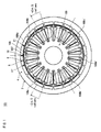
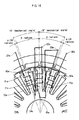
- Fig. 1 is a plan view showing a synchronous motor included in a synchronous motor drive system pertaining to a first embodiment of the present invention.
- Fig. 2 is a detail view of the synchronous motor shown in Fig. 1 .
- the synchronous motor 101 includes a rotor 2 and a stator 103.
- the rotor 2 includes a rotor core 4 and a plurality of permanent magnets 5.
- the permanent magnets 5 are arranged circumferentially along a rotation direction of the rotor 2 in the rotor core 4 at equal angular intervals.
- the permanent magnets 5 form magnetic poles 6 composed of pairs of N-poles and S-poles.
- the N-poles and S poles are alternately arranged with respect to the stator 103.
- Each magnetic pole pair of an N-pole and an S-pole equals to 2 ⁇ electrical radians, and is arranged so that each magnetic pole equals to ⁇ electrical radians.
- the rotor 2 has 20 magnetic poles, and the electrical angle is ten times the mechanical angle.
- Fig. 1 points 10 and 11 between magnetic poles of the rotor 2 are shown.
- the points 10 and 11 between magnetic poles of the rotor 2 indicate positions of magnetic neutral points between the N-poles and the S-poles formed by the permanent magnets 5 arranged in the rotor 2.
- the points 10 and 11 between magnetic poles coincide with mechanical positions midway between two magnets.
- an N-pole changes over to an S-pole at a point 10 between magnetic poles
- an S-pole changes over to an N-pole at a point 11 between magnetic poles.
- a point 11' between magnetic poles is the same as the point 11 between magnetic poles in terms of electrical angle, but is different from the point 11 between magnetic poles in terms of mechanical angle.
- a stator teeth group 108b is arranged with an offset of -60 mechanical degrees, that is, +2 ⁇ /3 electrical radians with respect to a stator teeth group 108a.
- a stator teeth group 108c is arranged with an offset of +60 mechanical degrees, that is, +4 ⁇ /3 electrical radians (i.e. -2 ⁇ /3 electrical radians) with respect to the stator teeth group 108a. Accordingly, the stator teeth group 108a, the stator teeth group 108b, and the stator teeth group 108c are arranged at intervals of 2 ⁇ /3 electrical radians.
- stator teeth group sets each composed of the stator teeth group 108a, the stator teeth group 108b, and the stator teeth group 108c are arranged circumferentially (so there are also a stator teeth group 108a', a stator teeth group 108b', and a stator teeth group 108c').
- Fig. 2 shows the structure of the stator teeth group 108a. This structure also applies to the stator teeth group 108b and the stator teeth group 108c.
- the stator teeth group 108a is composed of three consecutive stator teeth 171a, 172a, and 173a.
- the stator teeth 171a, 172a, and 173a are respectively wound with the stator coils 191a, 192a, and 193a by concentrated winding such that the winding direction of each of the stator coils 191a, 192a, and 193a is alternately opposite to each other.
- the stator tooth 171a is positioned at +20 mechanical degrees (i.e. with an additional offset of + ⁇ /9 radians besides an offset of ⁇ radians) with respect to the stator tooth 172a.
- the stator tooth 173a is positioned at -20 mechanical degrees (i.e. with an additional offset of - ⁇ /9 radians besides an offset of ⁇ radians) with respect to the stator tooth 172a.
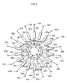
- Fig. 3 is a view illustrating stator coil connections of the synchronous motor shown in Fig. 1 .
- the alphabetical letters a, b, and c following the reference signs of the stator coil terminals shown in the figure correspond to coils belonging to the stator teeth groups 108a, 108b, and 108c, respectively.
- the three stator coils 191 a, 192a, and 193 a belonging to the stator teeth group 108a respectively have coil terminals 121a, 122a, and 123a.
- the coil terminals 121a, 122a, and 123a separately extend outside to be connected to connection terminals of the inverters (i.e. motor drivers).
- the three coil terminals 121b, 122b, and 123b in the stator teeth group 108b extend outside to be connected to separate connection terminals of the inverters (i.e. motor drivers).
- the three coil terminals 121c, 122c, and 123c in the stator teeth group 108c separately extend outside to be connected to connection terminals of the inverters (i.e. motor drivers).
- the three stator coils 191a, 192a, and 193a belonging to the stator teeth group 108a have coil terminals 124a, 125a, and 126a, respectively.
- the coil terminals 124a, 125a, and 126a are connected to the first, the second, and the third neutral points, respectively.
- This also applies to the three coil terminals 124b, 125b, and 126b belonging the stator teeth group 108b, and the three coil terminals 124c, 125c, and 126c belonging to the stator teeth group 108c.
- stator coil terminals in different stator teeth groups 108a, 108b, and 108c are connected to common neutral points in a manner such that the connected terminals have a phase difference of 2 ⁇ /3 radians with each other. More specifically, coil terminals 124a, 124b, and 124c are connected to the first neutral point. Coil terminals 125a, 125b, and 125c are connected to the second neutral point. Coil terminals 126a, 126b, and 126c are connected to the third neutral point. Although in this example the first, second, and third neutral points are electrically separated, two or all of them may be electrically connected.
- Teeth groups 108a there are two rotor teeth groups 108a, two rotor teeth groups 108b, and two rotor teeth groups 108c. Teeth groups with the same one of the alphabetical letters a, b, and c each have the same positional relations in terms of electrical angle with respect to the magnetic poles of the rotor. Accordingly, three consecutive groups among six stator teeth groups may have a neutral point connection. It is also possible that three alternately arranged stator teeth groups have a neutral point connection. It is even possible that all six stator teeth groups have a neutral point connection.
- stator teeth are arranged at different intervals from the magnetic poles of the rotor. Every three circumferentially consecutive stator teeth belong to one of the plurality of stator teeth groups. Three stator teeth in each stator teeth group are connected to separate external terminals.
- stator coils belonging to different stator teeth groups may be commonly connected if condition permits.
- stator coil 191a in the stator teeth group 108a and the stator coil 191a' in the stator teeth group 108a' may be connected to a common external terminal, because these stator coils are supplied with currents of the same phase.
- the stator coils may be separately connected to external terminals.
- Figs. 4A, 4B, and 4C show positional relations between a stator and a rotor pertaining to the first embodiment of the present invention.
- Fig. 4A shows the positional relation in a certain state.
- Fig. 4B shows the positional relation in the state in which the rotor 2 has been rotated by 2 mechanical degrees (i.e. ⁇ /9 electrical radians) anti-clockwise from the state shown in Fig. 4A.
- Fig. 4C shows the positional relation in the state in which the rotor 2 has been rotated by 2 mechanical degrees (i.e. ⁇ /9 electrical radians) anti-clockwise from the state shown in Fig. 4B .
- Fig. 5 shows currents supplied to the stator coils shown in Figs. 4A, 4B, and 4C . Time points shown as (a), (b), and (c) in Fig. 5 correspond to the positional relations shown in Fig. 4A, Fig. 4B, and Fig. 4C
- Fig. 4B shows the positional relation in the state in which the rotor 2 has been rotated by 2 mechanical degrees (i.e. ⁇ /9 electrical radians) anti-clockwise from the state shown in Fig. 4A .
- the center of the stator tooth 172a and the point 10 between magnetic poles of the rotor are aligned, as indicated by the chain line.
- the center of the stator tooth 173a and the point 11 between magnetic poles of the rotor are not aligned.
- the center of the stator tooth 171a and the point 11' between magnetic poles of the rotor are not aligned.
- Fig. 4C shows the positional relation in the state in which the rotor 2 has been rotated by 2 mechanical degrees (i.e. ⁇ /9 electrical radians) anti-clockwise from the state shown in Fig. 4B .
- the center of the stator tooth 171a and the point 11' between magnetic poles of the rotor are aligned, as indicated by the chain line.
- the center of the stator tooth 173a and the point 11 between magnetic poles of the rotor are not aligned.
- the center of the stator tooth 172a and the point 10 between magnetic poles of the rotor are not aligned.
- Fig. 5 shows temporal transitions of currents applied to the stator coils 191a, 192a, and 193a.
- the current supplied to the stator coil 192a the current supplied to the stator coil 193a is advanced by ⁇ /9 radians.
- the current supplied to the stator coil 192a the current supplied to the coil terminal 191a is delayed by ⁇ /9 radians.
- the stator coil 193a is arranged with an additional offset of - ⁇ /9 radians besides an offset of ⁇ electrical radians.
- the current supplied to the stator coil 193a is advanced by ⁇ /9 radians.
- the stator coil 191a is arranged with an additional offset of + ⁇ /9 radians besides an offset of ⁇ electrical radians.
- the current supplied to the stator coil 191 a is delayed by ⁇ /9 radians. This maximizes the current flowing to a stator coil wound around a stator tooth in the positional relation in which the center of the stator tooth and a point between magnetic poles of the rotor are aligned.
- Fig. 6 shows an overall structure of the synchronous motor drive system pertaining to the first embodiment of the present invention.
- the synchronous motor drive system includes the motor driver and the synchronous motor 101.
- the motor driver includes a DC power supply 40 and inverters 41, 42, and 43.
- the inverters 41, 42, and 43 each generate three-phase currents to supply to the synchronous motor 101.
- the output currents 41 a, 41b, and 41 c supplied from the inverter 41 are out of phase from each other by 2 ⁇ /3 radians.
- the output currents 42a, 42b, and 42c supplied from the inverter 42 are out of phase from each other by 2 ⁇ /3 radians.
- the output currents 43a, 43b, and 43c supplied from the inverter 43 are out of phase from each other by 2 ⁇ /3 radians.
- the phase of the output current 42a is advanced by ⁇ /9 radians from the output current 41 a.
- the phase of the output current 43a is advanced by ⁇ /9 radians from the output current 42a. This also applies to the output currents 41b, 42b, and 43b.
- the phase of the output current 42b is advanced by ⁇ /9 radians from the output current 41b.
- the phase of the output current 43b is advanced by ⁇ /9 radians from the output current 42b.
- the phase of the output current 42c is advanced by ⁇ /9 radians from the output current 41c.
- the phase of the output current 43c is advanced by ⁇ /9 radians from the output current 42c.
- the output currents 41a, 42a, and 43a correspond to the currents 191a, 192a, and 193a in Fig. 5 , respectively.
- the intervals between the magnet poles of the rotor are 18 mechanical degrees ( ⁇ electrical radians) while the intervals between three consecutive stator teeth belonging to a stator teeth group are 20 mechanical degrees.
- consecutive stator teeth belonging to a stator teeth group are arranged to have a phase difference of ( ⁇ + ⁇ /9) electrical radians from each other.
- the stator coils wound around the stator teeth are supplied with currents with a phase difference of ⁇ /9 radians from each other. This maximizes the magnet torque generated between the stator teeth and the magnetic poles, on a tooth to tooth basis, whereby the total torque is increased.
- each stator tooth yields the maximum torque at different times, namely, with a time difference corresponding to a phase difference of ⁇ /9 radians from each other. As a result, the torque ripple having a primary cycle of ⁇ /3 radians can be cancelled out.
- the phases of currents are adjusted so as to maximize the current flowing to a stator coil when the center of the stator tooth and the point between magnetic poles of the rotor are aligned.
- the synchronous motor 101 is what is called an interior permanent magnet synchronous motor that has permanent magnets arranged inside the rotor core. Accordingly, the synchronous motor is able to utilize reluctance torque resulting from a difference in magneto-resistance, along with the magnet torque generated by the permanent magnets.
- the stator coils on the stator teeth concentrated winding is adopted for the stator coils on the stator teeth. Consequently, the coils at the end surfaces of the stator, i.e. coil ends, can be reduced in size, which contributes to downsizing of the synchronous motor. Additionally, the coil ends do not contribute to torque even during application of a current. By reducing the coil ends in size, a copper loss, which is a Joule heat loss due to resistance of the coils during the application of the current, can be reduced. As a result, a high efficiency is achieved.
- the synchronous motor 101 is so-called an outer rotor type where the rotor is placed outside the outer circumference of the stator. Consequently, assuming the volumes being the same, the diameter of the rotor may be longer than an inner rotor type structure where the stator is placed inside the inner circumference of the stator. Accordingly, even for the synchronous motor that has 20 poles, it is not necessary to reduce the size of the permanent magnets. This prevents a decline of the effective magnetic flux.
- the synchronous motor 101 has 20 rotor magnetic poles and 18 stator teeth
- a synchronous motor with the following structure can achieve similar effects.
- the number of stator teeth is a multiple of nine such as 9 or 27, and the number of magnetic poles of the rotor is a multiple of 10, thereby constituting a combination of 10q poles and 9q teeth (q being a positive integer). This holds true with a combination of 8q poles and 9q teeth (q being a positive integer), and a combination of 10q poles and 12q teeth (q being a positive integer).
- the two stator teeth groups 108a and 108a' having a neutral point connection are arranged symmetrically about the axis.
- the two stator teeth groups 108b, and 108b' having a neutral point connection are arranged symmetrically about the axis.
- the two stator teeth groups 108c and 108c' having a neutral point connection are arranged symmetrically about the axis.
- stator teeth groups having a neutral point connection are arranged at angular intervals of 120 mechanical degrees with respect to the axis. Accordingly, the composite attraction in the radial direction caused by the stator teeth when a current is applied to the coils is 0, and no magnetic attraction acts on the rotor.
- the synchronous motor drive system of compact size, high output, low vibration, low noise, and improved efficiency is provided.
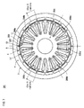
- Fig. 7 is a plan view showing the synchronous motor included in the synchronous motor drive system pertaining to a second embodiment of the present invention.
- Fig. 8 is a detail view of the synchronous motor shown in Fig. 7 .
- the synchronous motor 201 according to the second embodiment differs from the synchronous motor 101 according to the first embodiment with respect to the structure of a stator 203. Concretely, stator teeth 207 belonging to a stator teeth group 208 are arranged at different intervals.
- the stator 203 includes a plurality of stator teeth 207 arranged diametrically opposite to the rotor 2.
- Fig. 8 shows the structure of the stator teeth group 208a. This structure also applies to the stator teeth group 208b and the stator teeth group 208c.
- the stator teeth group 208a is composed of three consecutive stator teeth 271a, 272a, and 273a.
- the stator teeth 271a, 272a, and 273 a are respectively wound with the stator coils 291a, 292a, and 293a by concentrated winding such that the winding direction of each of the stator coils 291a, 292a, and 293a is alternately opposite to each other.
- the stator tooth 271a is positioned at +19 mechanical degrees (i.e. with an additional offset of + ⁇ /18 radians besides an offset of ⁇ radians) with respect to the stator tooth 272a.
- the stator tooth 273a is positioned at -19 mechanical degrees (i.e. with an additional offset of - ⁇ /18 radians besides an offset of ⁇ radians) with respect to the stator tooth 272a.
- Fig. 9 is a view illustrating stator coil connections of the synchronous motor shown in Fig. 7 .
- the alphabetical letters a, b, and c following the reference signs of the stator coil terminals shown in the figure correspond to coils belonging to the stator teeth groups 208a, 208b, and 208c, respectively.
- the three stator coils 291a, 292a, and 293a belonging to the stator teeth group 208a respectively have coil terminals 221a, 222a, and 223a.
- the coil terminals 221a, 222a, and 223a extend outside to be connected to separate connection terminals of inverters (i.e. motor drivers).
- the stator coil terminals in different stator teeth groups 208a, 208b, and 208c are connected to common neutral points in a manner such that the connected terminals have a phase difference of 2 ⁇ /3 radians with each other.
- Figs. 10A, 10B, and 10C show positional relations between a stator and a rotor pertaining to the second embodiment of the present invention.
- Fig. 10A shows the positional relation in a certain state.
- Fig. 10B shows the positional relation in the state in which the rotor 2 has been rotated by 1 mechanical degree (i.e. ⁇ /18 electrical radians) anti-clockwise from the state shown in Fig. 10A.
- Fig. 10C shows the positional relation in the state in which the rotor 2 has been rotated by 1 mechanical degree (i.e. ⁇ /18 electrical radians) anti-clockwise from the state shown in Fig. 10B .
- Fig. 11 shows currents supplied to the stator coils shown in Figs. 10A, 10B, and 10C . Time points shown as (a), (b), and (c) in Fig. 11 correspond to the positional relations shown in Figs. 10A, Fig. 10B, and Fig. 10C
- Fig. 10B shows the positional relation in the state in which the rotor has been rotated by 1 mechanical degree (i.e. ⁇ /18 electrical radians) anti-clockwise from the state shown in Fig. 10A .
- the center of the stator tooth 272a and the point 10 between magnetic poles of the rotor are aligned, as indicated by the chain line.
- the center of the stator tooth 273a and the point 11 between magnetic poles of the rotor are not aligned.
- the center of the stator tooth 271a and the point 11' between magnetic poles of the rotor are not aligned
- Fig. 10C shows the positional relation in the state in which the rotor has been rotated by 1 mechanical degree (i.e. ⁇ /18 electrical radians) anti-clockwise from the state shown in Fig. 10B .
- the center of the stator tooth 271a and the point 11' between magnetic poles of the rotor are aligned, as indicated by the chain line.
- the center of the stator tooth 273a and the point 11 between magnetic poles of the rotor are not aligned.
- the center of the stator tooth 272a and the point 10 between magnetic poles of the rotor are not aligned.
- Fig. 11 shows temporal transitions of currents applied to the stator coils 291a, 292a, and 293 a.
- Fig. 11 shows temporal transitions of currents supplied to the stator coils 291a, 292a, and 293a.
- the current supplied to the stator coil 292a With respect to the current supplied to the stator coil 292a, the current supplied to the stator coil 293a is advanced by ⁇ /18 radians.
- the current supplied to the coil terminal 291a is delayed by ⁇ /18 radians.
- the stator tooth 293a is arranged with an additional offset of - ⁇ /18 radians besides an offset of ⁇ electrical radians.
- the current supplied to the stator coil 293a is advanced by ⁇ /18 radians.
- the coil 291 a is arranged with an additional offset of + ⁇ /18 radians besides an offset of ⁇ electrical radians.
- the current supplied to the stator coil 291a is delayed by ⁇ /18 radians. This maximizes the current flowing to a stator coil wound around a stator tooth in the positional relation in which the center of the stator tooth and a point between magnetic poles of the rotor are aligned.
- the synchronous motor 201 has six stator teeth groups arranged at equal intervals. Three stator teeth belong to each stator teeth group, and these stator teeth are arranged at equal intervals. However, note that not all of 18 stator teeth are arranged at equal intervals. In this way, simply by arranging the stator teeth such that the stator teeth have slight phase differences with each other, and by supplying currents with slight phase differences to the stator teeth in accordance with the differences in arrangement, torque ripples is reduced, while a decrease in torque is suppressed.
- the synchronous motor drive system of compact size, high output, low vibration, low noise, and improved efficiency is provided.
- Fig. 12 is a detail view showing the synchronous motor included in the synchronous motor drive system pertaining to a third embodiment of the present invention.
- the third embodiment differs from the second embodiment in that winding directions of the stator coils each wound around the respective stator teeth are identical to each other.
- stator coils 291a, 392a, and 293a are wound around the stator teeth 271a, 272a, and 273a.
- the winding directions of the stator coils 291a, 392a, and 293a are identical to each other.
- stator coils 291a, 392a, and 293a start at terminals 221a, 322a, and 223a and end at terminals 224a, 325a, and 226a, respectively.
- the terminals 221a and 223a at which the winding starts serve as input terminals
- the terminals 224a and 226a at which the winding ends serve as neutral point terminals.
- the terminal 325a at which the winding ends serves as an input terminal
- the terminal 322a at which the winding starts serves as a neutral point terminal.
- stator coils 291a, 392a, and 293a are supplied with the currents shown in Fig. 11 .
- two consecutive stator coils generate magnet fields having opposite polarities.
- the winding directions of the stator coils 291a, 392a, and 293a are identical to each other. Now, it is assumed that the winding of the stator coils 291a, 392a, and 293a starts at terminals 221a, 322a, and 223a and end at terminals 224a, 325a, and 226a, respectively. In all the stator coils 291a, 392a, and 293a, the terminals 221a, 322a, and 223a at which the winding starts serve as input terminals, and the terminals 224a, 325a, and 226a at which the winding ends serve as neutral point terminals, respectively.
- Fig. 13 shows temporal transitions of currents supplied to the stator coils shown in Fig. 12B .
- the phase of the current supplied to the stator coil 392a is opposite relative to the current supplied to the stator coil 292a shown in Fig. 11 .
- two consecutive stator coils generate magnet fields having opposite polarities
- the third embodiment As has been described, according to the third embodiment, a decrease in torque is suppressed, while the torque ripple is reduced. Further, the winding directions of the stator coils are made identical to each other in the manufacturing processes, whereby manufacturing variability in the stator coils is reduced. Thus, a reliable synchronous motor drive system is provided. Meanwhile, although the third embodiment is described as a modification of the second embodiment, this is not limiting. The third embodiment can be applied to the first embodiment as well.
- a fourth embodiment is the same as the first embodiment with respect to the structure of the synchronous motor. Specifically, three stator teeth of each stator teeth group are arranged with additional offsets of ⁇ /9 radians besides offsets of ⁇ radians. In the fourth embodiment, the phase of the current supplied to each stator coil differs from the first embodiment. A description is given below of the current application method in the fourth embodiment.
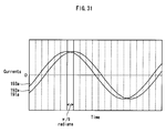
- Fig. 14 shows temporal transitions of currents applied to the stator coils in the fourth embodiment of the present invention.
- the current supplied to the stator coil 493a and the current supplied to the stator coil 491 a are out of phase by 2 ⁇ /9 radians. This is the same as the first embodiment. However, with respect to the current supplied to the stator coil 192a, the current supplied to the stator coil 493a is advanced by 5 ⁇ /36 radians. Further, with respect to the current supplied to the stator coil 192a, the current supplied to the stator coil 491 a is delayed by 3 ⁇ /36 radians.
- the fourth embodiment is described as a modification of the first embodiment, the fourth embodiment can also be applied to the second embodiment.
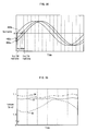
- Fig. 15 shows temporal transitions of torque.
- the line represented by T0 indicates temporal transitions of torque in a conventional synchronous motor drive system.
- the line T3 indicates temporal transitions of torque in the synchronous motor drive system of the first embodiment.
- the line T4 indicates temporal transitions of torque in the synchronous motor drive system of the fourth embodiment.
- FIG. 16 is a detail view of a conventional synchronous motor.
- Patent Literature 2 Japanese patent application publication No. 2003-244915
- the stator coils 91a, 92a, and 93a are connected in series. Specifically, the coil terminal 24a of the stator coil 91 a and the coil terminal 22a of the stator coil 92a are connected with each other. The coil terminal 25a of the stator coil 92a and the coil terminal 23a of the stator coil 93a are connected with each other. As a result, the coil terminal 21a of the stator coil 91 a serves as an input terminal, and the coil terminal 26a of the stator coil 93a serves as a neutral point terminal.
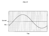
- Fig. 17 shows temporal transitions of currents applied to the stator coils in the conventional synchronous motor.
- a positional relation where the center of the stator tooth 72a and the point 10 between magnetic poles of the rotor are aligned.
- it is possible to maximize magnet torque generated between the stator tooth 72a and the magnetic poles by supplying currents while adjusting the current phases so as to maximize the current flowing to the stator coil 92a.
- the center of the stator tooth 71a and the point 11' between magnetic poles of the rotor are not aligned.
- the center of the stator tooth 73a and the point 11 between magnetic poles of the rotor are not aligned, either. Accordingly, it is not possible to maximize magnet torque generated between the stator tooth 71a and the magnetic poles. It is not possible to maximize magnet torque generated between the stator tooth 73a and the magnetic poles, either.
- the average torque obtained in the first embodiment and that obtained in the fourth embodiment are higher than that obtained in the conventional structure. Further, the torque ripple represented by a ratio of a difference between maximum torque and minimum torque to average torque is approximately 6% according to the conventional technology. On the other hand, the torque ripple is lower than 1% in the first embodiment of the present invention. It is approximately 1% in the fourth embodiment.
- the present embodiment of the present invention As has been described so far, according to the present embodiment of the present invention, a decrease in torque is suppressed, while the torque ripple is reduced.
- the synchronous motor drive system of compact size, high output, low vibration, low noise, and improved efficiency is provided.
- Fig. 18 is a plan view showing the synchronous motor included in the synchronous motor drive system pertaining to a fifth embodiment of the present invention.
- Fig. 19 is a detail view of the synchronous motor shown in Fig. 18 .
- a synchronous motor 501 of the fifth embodiment differs from the synchronous motor 101 of the first embodiment with respect to the structure of stator coils 509.
- the stator teeth group 508a is composed of three consecutive stator teeth 571a, 572a, and 573a.
- the stator teeth 571a, 572a, and 573a are arranged in a manner identical to the stator teeth 171a, 172a, and 173a of the first embodiment.
- the stator tooth 571a is wound with a part of stator coil 591a (having N1 number of turns).
- the stator tooth 573a is wound with a part of stator coil 592a (having N2 number of turns).
- the stator tooth 572a is wound with the remaining part of the stator coil 591 a (having N21 number of turns) and the remaining part of the stator coil 592a (having N22 number of turns).
- the stator coil 591a is wound around both the stator tooth 571a and the stator tooth 572a, causing the two wound parts to generate magnetic fields having polarities opposite to each other.
- the stator coil 592a is wound around both the stator tooth 572a and the stator tooth 573a, causing the two wound parts to generate magnetic fields having polarities opposite to each other. Further, when the stator coils 591 a and 592a are supplied with currents having the same phase, the two parts in the stator tooth 572a wound with the stator coils 591a and 592a generate magnet fields having the same polarity.
- Fig. 20 is a view illustrating stator coil connections of the synchronous motor shown in Fig. 18 .
- the alphabetical letters a, b, and c following the reference signs of the stator coil terminals shown in the figure correspond to coils belonging to the stator teeth groups 508a, 508b, and 508c, respectively.
- the two stator coils 591a and 592a belonging to the stator teeth group 508a respectively have coil terminals 521a and 523a.
- the coil terminals 521a and 523a extend outside to be connected to separate connection terminals of the inverters (i.e. motor drivers).
- the two coil terminals 521b and 523b in the stator teeth group 508b extend outside to be connected to separate connection terminals of the inverters (i.e. motor drivers).
- the two coil terminals 521c and 523c in the stator teeth group 508c extend outside to be connected to separate connection terminals of the inverters (i.e. motor drivers).
- stator coil terminals in different stator teeth groups 508a, 508b, and 508c are connected to common neutral points in a manner such that the connected terminals have a phase difference of 2 ⁇ /3 radians with each other. More specifically, coil terminals 522a, 522b, and 522c are connected to the first neutral point. Coil terminals 524a, 524b, and 524c are connected to the second neutral point.
- Figs. 21A, 21B, and 21C show positional relations between a stator and a rotor pertaining to the fifth embodiment of the present invention.
- Fig. 21A shows the positional relation in a certain state.
- Fig. 21B shows the positional relation in the state in which the rotor 2 has been rotated by 2 mechanical degrees (i.e. ⁇ /9 electrical radians) anti-clockwise from the state shown in Fig. 21A.
- Fig. 21C shows the positional relation in the state in which the rotor 2 has been rotated by 2 mechanical degrees (i.e. ⁇ /9 electrical radians) anti-clockwise from the state shown in Fig. 10B .
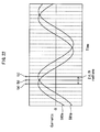
- Fig. 22 shows currents supplied to the stator coils shown in Figs. 21A, 21B, and 21C . Time points shown as (a), (b), and (c) in Fig. 22 correspond to the positional relations shown in Fig. 21A, Fig. 21B, and Fig. 21C
- Fig. 21B shows the positional relation in the state in which the rotor has been rotated by 2 mechanical degrees (i.e. ⁇ /9 electrical radians) anti-clockwise from the state shown in Fig. 21A .
- the center of the stator tooth 572a and the point 10 between magnetic poles of the rotor are aligned, as indicated by the chain line.
- the center of the stator tooth 573a and the point 11 between magnetic poles of the rotor are not aligned.
- the center of the stator tooth 571a and the point 11' between magnetic poles of the rotor are not aligned.
- the numbers of turns of the stator teeth 591a and 592a are adjusted so that vector synthesis of the currents supplied to the stator coils 591 a and 592a is maximized in the positional relation shown in Fig. 21B . As a result, it is possible to maximize magnet torque generated between the stator tooth 572a and the magnetic poles.
- Fig. 21C shows the positional relation in the state in which the rotor has been rotated by 2 mechanical degree (i.e. ⁇ /9 electrical radians) anti-clockwise from the state shown in Fig. 21B .
- the center of the stator tooth 571a and the point 11' between magnetic poles of the rotor are aligned, as indicated by the chain line.
- the center of the stator tooth 573a and the point 11 between magnetic poles of the rotor are not aligned.
- the center of the stator tooth 572a and the point 10 between magnetic poles of the rotor are not aligned.
- Fig. 22 shows temporal transitions of currents supplied to the stator coils 591a and 592a. With respect to the current supplied to the stator coil 591a, the current supplied to the stator coil 592a is advanced by 2 ⁇ /9 radians.
- the stator tooth 573a is arranged with an additional offset of - ⁇ /9 radians besides an offset of ⁇ electrical radians.
- the stator tooth 571a is arranged with an additional offset of + ⁇ /9 radians besides an offset of ⁇ electrical radians.
- the current supplied to the stator coil 592a is advanced by 2 ⁇ /9 radians.
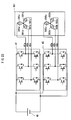
- Fig. 23 shows an overall structure of the synchronous motor drive system pertaining to the first embodiment of the present invention.
- the synchronous motor drive system includes the motor driver and the synchronous motor 501.
- the motor driver includes a DC power supply 40 and inverters 41 and 42.
- the inverters 41 and 42 each generate three-phase currents to supply to the synchronous motor 501.
- the output currents 41 a, 41b, and 41c supplied from the inverter 41 are out of phase from each other by 2 ⁇ /3 radians.
- the output currents 42a, 42b, and 42c supplied from the inverter 42 are out of phase from each other by 2 ⁇ /3 radians.
- the output currents 41 a and 42a are out of phase from each other by 2 ⁇ /9 radians.
- the output current 41 b and the output current 42b are out of phase from each other by 2 ⁇ /9 radians.
- the output current41c and the output current 42c are out of phase from each other by 2 ⁇ /9 radians.
- the output currents 41a and 42a correspond to the currents 591a and 592a in Fig. 22 , respectively.
- the magnet torque obtained from the stator teeth 571a, 572a, and 573a is each maximized, while the number of the three-phase inverters are reduced to two. Accordingly, the total torque is increased.
- stator coils are wound around the stator teeth by a method similar to concentrated winding. For this reason, compared with the synchronous motor in which stator coils are wound by distributed winding, coils extending outwardly from the ends of the stator (i.e. coil end portions) can be lowered, and the size of the synchronous motor is reduced.
- two stator coils wound around the stator teeth 672a have N21 and N22 number of turns different from each other. Since the other structures except the above point are identical to the fifth embodiment, a description is omitted.
- Fig. 24 is a vector diagram illustrating flux generated by stator teeth pertaining to the sixth embodiment of the present invention.
- the vectors represent flux generated from the stator teeth.
- the size and direction of each vector indicates the flux number and the phase of the generated flux.
- the flux to be generated from the stator tooth 572a is out of phase by ( ⁇ + ⁇ ) electrical radians.
- the flux to be generated from the stator tooth 572a is out of phase by ( ⁇ + ⁇ ) electrical radians (the phase difference includes + ⁇ radians since the flux to be generated is opposite to each other).
- N1, N2, N21, and N22 numbers of turns satisfy the following relations.
- N ⁇ 1 N ⁇ 2
- N ⁇ 21 N ⁇ 1 ⁇ sin ⁇ / sin ⁇ + ⁇
- N ⁇ 22 N ⁇ 2 ⁇ sin ⁇ / sin ⁇ + ⁇
- Fig. 25 shows temporal transitions of currents applied to the stator coils in the sixth embodiment of the present invention.
- the current supplied to the stator coil 592a is advanced by 2 ⁇ /9 radians.
- the line 594x indicates vector synthesis of the currents supplied to the stator coil 591a (having N21 number of turns) and the stator coil 592a (having N22 number of turns) both wound around the stator tooth 572a.
- the synchronous motor yield increased torque, while decreasing the torque ripple, compared with motors using conventional technology. Furthermore, in the sixth embodiment, the number of the three-phase inverters is reduced more significantly than the fourth embodiment.
- Fig. 26 shows temporal transitions of torque.
- the line represented by T0 indicates temporal transitions of torque in the conventional synchronous motor drive system.
- the line T3 indicates temporal transitions of torque in the synchronous motor drive system of the fifth embodiment.
- the line T4 indicates temporal transitions of torque in the synchronous motor drive system of the sixth embodiment.
- the line T0 is the same as that shown in Fig. 15 .
- the average torque obtained in the fifth embodiment and that obtained in the sixth embodiment are higher than the conventional structure.
- the torque ripple represented by a ratio of a difference between maximum torque and minimum torque to average torque is approximately 6% according to the conventional technology.
- the torque ripple is lower than 1% in the fifth embodiment of the present invention. It is approximately 1% in the sixth embodiment.
- the present embodiment of the present invention As has been described so far, according to the present embodiment of the present invention, a decrease in torque is suppressed, while the torque ripple is reduced.
- the synchronous motor drive system of compact size, high output, low vibration, low noise, and improved efficiency is provided.
- Fig. 27 is a detail view showing the synchronous motor included in the synchronous motor drive system pertaining to a seventh embodiment of the present invention.
- the seventh embodiment adopts the structure of the stator according to the second embodiment and the structure of the coils according to the fifth embodiment.
- the stator teeth group is composed of three consecutive stator teeth 771a, 772a, and 773a.
- the stator tooth 771a is positioned at +19 mechanical degrees (i.e. with an additional offset of + ⁇ /18 radians besides an offset of ⁇ radians) with respect to the stator tooth 772a.
- the stator tooth 773a is positioned at -19 mechanical degrees (i.e. with an additional offset of - ⁇ /18 radians besides an offset of ⁇ radians) with respect to the stator tooth 772a.
- the stator tooth 771a is wound with a part of stator coil 791a (having N1 number of turns).
- the stator tooth 773a is wound with a part of stator coil 792a (having N2 number of turns).
- the stator tooth 772a is wound with the remaining part of the stator coil 791 a (having N21 number of turns) and the remaining part of the stator coil 792a (having N22 number of turns).
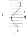
- Fig. 28 shows temporal transitions of currents applied to the stator coils in the seventh embodiment of the present invention.
- the current supplied to the stator coil 792a is advanced by ⁇ /9 radians.
- stator tooth 773a is arranged with an additional offset of - ⁇ /18 radians besides an offset of ⁇ electrical radians.
- stator tooth 771a is arranged with an additional offset of + ⁇ /18 radians besides an offset of ⁇ electrical radians.
- the current supplied to the stator coil 792a is advanced by ⁇ /9 radians.
- the current flowing to the stator coil 792a is maximized when the center of the stator tooth 773a and the point 11 between magnetic poles of the rotor are aligned, whereby the magnet torque generated between the stator tooth 773a and the magnet poles is maximized.
- the vector synthesis of the currents flowing to the stator coils 791a and 792a is maximized when the center of the stator tooth 772a and the point 10 between magnetic poles of the rotor are aligned, whereby the magnet torque generated between the stator tooth 772a and the magnet poles is maximized.
- the current flowing to the stator coil 791a is maximized when the center of the stator tooth 771a and the point 11' between magnetic poles of the rotor are aligned, whereby the magnet torque generated between the stator tooth 771 a and the magnet poles is maximized.
- the magnet torque obtained from each stator tooth is maximized. Accordingly, the total torque is increased.
- the increase ratio (N21 + N22) / N1 it is 1 / cos ( ⁇ /18) in the seventh embodiment, while it is 1 / cos ( ⁇ /9) in the fifth embodiment. That is to say that the increase ratio is smaller in the seventh embodiment than the fifth embodiment (approximately 95%). Accordingly, the seventh embodiment is useful for the purpose of reducing the size of the synchronous motor.
- An eighth embodiment differs from the fifth embodiment with respect to the structure of coils. Apart from that, the eighth embodiment is the same as the fifth embodiment.
- Fig. 29 is a detail view showing the synchronous motor included in the synchronous motor drive system pertaining to the eighth embodiment of the present invention.
- the stator teeth group is composed of three consecutive stator teeth 871a, 872a, and 873a.
- the stator tooth 871a is positioned at +20 mechanical degrees (i.e. with an additional offset of + ⁇ /9 radians besides an offset of ⁇ radians) with respect to the stator tooth 872a.
- the stator tooth 873a is positioned at -20 mechanical degrees (i.e. with an additional offset of - ⁇ /9 radians besides an offset of ⁇ radians) with respect to the stator tooth 872a.
- the stator tooth 871a is wound with a stator coil 891a.
- the stator tooth 873a is wound with a stator coil 892a.
- the stator tooth 872a is not wound with a stator coil.
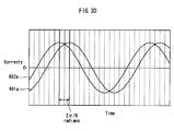
- Fig. 30 shows temporal transitions of currents applied to the stator coils in the eighth embodiment of the present invention.
- the current supplied to the stator coil 892a is advanced by 2 ⁇ /9 radians.
- stator tooth 873a is arranged with an additional offset of - ⁇ /9 radians besides an offset of ⁇ electrical radians.
- stator tooth 871a is arranged with an additional offset of + ⁇ /9 radians besides an offset of ⁇ electrical radians.
- the current supplied to the stator coil 892a is advanced by 2 ⁇ /9 radians.
- the current flowing to the stator coil 892a is maximized when the center of the stator tooth 873a and the point 11 between magnetic poles of the rotor are aligned, whereby the magnet torque generated between the stator tooth 873a and the magnet poles is maximized.
- the current flowing to the stator coil 891 a is maximized when the center of the stator tooth 871a and the point 11' between magnetic poles of the rotor are aligned, whereby the magnet torque generated between the stator tooth 871a and the magnet poles is maximized.
- the magnet torque obtained from each stator tooth is maximized. Accordingly, the total torque is increased.
- the intervals between the stator teeth are 20 mechanical degrees, it is possible to change the intervals to 19 mechanical degrees to secure a larger space for the coils.
- stator tooth 872a is not wound with a stator coil
- stator tooth 872a may be wound with a sensor coil that is not identical to the driving coils. It is possible to specify the position of the rotor by detecting induced voltage in the sensor coil. The position of the rotor may also be specified by applying, to the sensor coil, a high frequency voltage that is not identical to the driving currents, and detecting the currents under influence of the inductance.
- the number of the three-phase inverters is reduced to two.
- the stator tooth 872a works with two consecutive stator teeth 871a and 873a to form a path from an N-pole to an S-pole of the magnetic poles of the rotor. Accordingly, the eighth embodiment is useful for the synchronous motor of a relatively small diameter that has difficulty in finding a large space for coils to increase the number of the stator teeth.
- stator coils belonging to a stator teeth group each extend to outside to be supplied with currents of different phases.
- present invention is not limited to this. Even when only two of three consecutive stator coils are supplied with currents of different phases, a certain level of effect is obtained. For example, Fig.
- stator coils 191a and 192a are supplied with currents of the same phase, whereas the stator coil 193a is supplied with a current that is advanced by ⁇ /9 radians with respect to the currents supplied to the stator coils 191a and 192a.
- M consecutive stator teeth in a stator teeth group can be arranged at intervals of at most ( ⁇ + 2 ⁇ /3M) electrical radians. Further, if the stator coils wound around consecutive stator teeth have properties to generate magnetic fields of alternately opposite phases in response to currents of the same phase, these stator coils can be supplied with currents having a phase difference within a range of ⁇ 2 ⁇ /3M radians from each other.
- stator teeth in a stator teeth group at intervals of at most ( ⁇ + ⁇ /3m) electrical radians.
- stator coils wound around consecutive stator teeth may be supplied with currents having a phase difference within a range of ⁇ ⁇ /3M radians from each other.
- Consecutive stator coils are arranged at intervals of at most ( ⁇ + ⁇ /15) electrical radians. Further, in two consecutive stator coils with one positioned at most ( ⁇ + ⁇ /15) electrical radians ahead of the other with respect to the rotation direction of the rotor, the current supplied to the one positioned ahead of the other is delayed by ( ⁇ + ⁇ /15) radians with respect to the current supplied to the other coil.
- M consecutive stator teeth in a stator teeth group can be arranged at intervals of at most ( ⁇ + 2 ⁇ /3M) electrical radians.
- These stator coils 591a and 592a may be supplied with currents having a phase difference within a range of ⁇ 2 ⁇ /3M radians from each other.
- stator teeth in a stator teeth group at intervals of at most ( ⁇ + ⁇ /3M) electrical radians.
- the stator coils 591a and 592a may be supplied with currents having a phase difference of at most 2 ⁇ /3M radians from each other.
- N ⁇ 1 N ⁇ 2
- N ⁇ 21 N ⁇ 1 ⁇ sin ⁇ / sin ⁇ + ⁇
- N ⁇ 22 N ⁇ 2 ⁇ sin ⁇ / sin ⁇ + ⁇
- N ⁇ 1 N ⁇ 2
- space factor of coils namely the proportion of stator coils to space in which the stator coils are disposed, is increased.
- the above relations also provide an effect that the synchronous motor yields increased torque while decreasing the torque ripple.
- the present invention is applicable to synchronous motor drive systems for compressors, electrical vehicles, hybrid vehicles, fuel-cell vehicles, and the like, as these synchronous motors require compact size, high efficiency, low vibration, and low noise.
Landscapes
- Engineering & Computer Science (AREA)
- Power Engineering (AREA)
- Permanent Magnet Type Synchronous Machine (AREA)
- Windings For Motors And Generators (AREA)
Applications Claiming Priority (3)
| Application Number | Priority Date | Filing Date | Title |
|---|---|---|---|
| JP2008142799 | 2008-05-30 | ||
| JP2008142798 | 2008-05-30 | ||
| PCT/JP2009/002364 WO2009144946A1 (fr) | 2008-05-30 | 2009-05-28 | Système de commande de moteur synchrone |
Publications (2)
| Publication Number | Publication Date |
|---|---|
| EP2290791A1 true EP2290791A1 (fr) | 2011-03-02 |
| EP2290791A4 EP2290791A4 (fr) | 2014-07-23 |
Family
ID=41376836
Family Applications (1)
| Application Number | Title | Priority Date | Filing Date |
|---|---|---|---|
| EP09754455.5A Withdrawn EP2290791A4 (fr) | 2008-05-30 | 2009-05-28 | Système de commande de moteur synchrone |
Country Status (4)
| Country | Link |
|---|---|
| US (1) | US8390165B2 (fr) |
| EP (1) | EP2290791A4 (fr) |
| JP (1) | JP5180297B2 (fr) |
| WO (1) | WO2009144946A1 (fr) |
Cited By (3)
| Publication number | Priority date | Publication date | Assignee | Title |
|---|---|---|---|---|
| FR2967529A1 (fr) * | 2010-11-12 | 2012-05-18 | Erneo | Machine electrique a bobinage dentaire a phases regroupees |
| CN104871426A (zh) * | 2012-12-17 | 2015-08-26 | 株式会社美姿把 | 无刷马达控制方法、无刷马达控制装置以及电动动力转向装置 |
| EP3293875A1 (fr) * | 2016-09-09 | 2018-03-14 | Black & Decker Inc. | Onduleur double pour moteur sans balai |
Families Citing this family (9)
| Publication number | Priority date | Publication date | Assignee | Title |
|---|---|---|---|---|
| US8471426B2 (en) * | 2011-05-03 | 2013-06-25 | Siemens Industry, Inc. | Electric machine with power taps |
| WO2012160841A1 (fr) * | 2011-05-23 | 2012-11-29 | 三菱電機株式会社 | Machine électrique rotative de type aimant permanent |
| US9300194B2 (en) * | 2011-11-09 | 2016-03-29 | Hamilton Sundstrand Corporation | Electromagnetic device |
| JP2014158396A (ja) * | 2013-02-18 | 2014-08-28 | Mitsubishi Electric Corp | 同期電動機の固定子 |
| US9755470B2 (en) * | 2014-10-30 | 2017-09-05 | Mitsubishi Electric Corporation | Rotary electric machine and electric power steering device using rotary electric machine |
| US10439479B2 (en) * | 2015-01-23 | 2019-10-08 | Mitsubishi Electric Corporation | Electric drive device |
| US11139722B2 (en) | 2018-03-02 | 2021-10-05 | Black & Decker Inc. | Motor having an external heat sink for a power tool |
| US20220200401A1 (en) | 2020-12-23 | 2022-06-23 | Black & Decker Inc. | Brushless dc motor with circuit board for winding interconnections |
| CN114865820A (zh) * | 2022-03-23 | 2022-08-05 | 江门市邦特电子电器有限公司 | 一种三相直流无刷电机及电机线方法 |
Family Cites Families (23)
| Publication number | Priority date | Publication date | Assignee | Title |
|---|---|---|---|---|
| US1545175A (en) * | 1916-05-08 | 1925-07-07 | Us Light & Heat Corp | Dynamo-electric machine |
| DE2744222C2 (de) * | 1977-09-30 | 1984-10-18 | Siemens AG, 1000 Berlin und 8000 München | Wicklungsanordnung für einen elektrischen Zweimotorenantrieb |
| JPH0748935B2 (ja) * | 1990-11-30 | 1995-05-24 | 日本ビクター株式会社 | 多相直流モータ |
| JP3364562B2 (ja) * | 1995-12-01 | 2003-01-08 | ミネベア株式会社 | モータ構造 |
| JPH09285088A (ja) | 1996-04-12 | 1997-10-31 | Hitachi Ltd | 永久磁石回転電機及びそれを用いた電動車両 |
| JP3812611B2 (ja) * | 1997-08-26 | 2006-08-23 | オリエンタルモーター株式会社 | 回転子位置センサ付き多相モータ |
| JP3428896B2 (ja) * | 1998-05-07 | 2003-07-22 | オークマ株式会社 | トルクリップルを低減したモータ |
| JP4032516B2 (ja) * | 1998-07-23 | 2008-01-16 | 株式会社デンソー | 自動車用電動駆動装置 |
| JP3419721B2 (ja) * | 1999-12-06 | 2003-06-23 | 三菱電機株式会社 | 車両用交流発電機 |
| DE10128696A1 (de) * | 2000-06-16 | 2002-01-03 | Aisin Seiki | Motor |
| JP4039074B2 (ja) | 2002-02-14 | 2008-01-30 | 松下電器産業株式会社 | 同期型モータ |
| JP2004064837A (ja) | 2002-07-26 | 2004-02-26 | Toyota Central Res & Dev Lab Inc | モータ駆動制御装置 |
| US20040251763A1 (en) * | 2003-06-13 | 2004-12-16 | Matsushita Electric Industrial Co., Ltd. | Motor |
| JP4468740B2 (ja) * | 2003-06-13 | 2010-05-26 | パナソニック株式会社 | モータ |
| JP4432396B2 (ja) * | 2003-07-14 | 2010-03-17 | 株式会社安川電機 | 9相モータ駆動装置 |
| JP2005073450A (ja) * | 2003-08-27 | 2005-03-17 | Matsushita Electric Ind Co Ltd | モータジェネレータ |
| US7936099B2 (en) * | 2005-07-28 | 2011-05-03 | Thyssenkrupp Presta Ag | Electric motor stator |
| JP2007166767A (ja) * | 2005-12-13 | 2007-06-28 | Nakamura Kogyosho:Kk | 分割スキュー積層コア及びその製造方法 |
| JP4745857B2 (ja) * | 2006-02-20 | 2011-08-10 | 三菱電機株式会社 | 電気機械 |
| JP4650323B2 (ja) * | 2006-03-29 | 2011-03-16 | トヨタ自動車株式会社 | 回転電機の巻線構造 |
| US7545069B2 (en) * | 2006-04-04 | 2009-06-09 | Ford Global Technologies, Llc | Electric machine winding arrangement |
| JP4842711B2 (ja) * | 2006-06-02 | 2011-12-21 | 東芝三菱電機産業システム株式会社 | 多相電動機 |
| JP2008005603A (ja) | 2006-06-21 | 2008-01-10 | Mitsubishi Electric Corp | 同期機、およびこれを発電機として用いた発電システム |
-
2009
- 2009-05-28 JP JP2010514378A patent/JP5180297B2/ja not_active Expired - Fee Related
- 2009-05-28 WO PCT/JP2009/002364 patent/WO2009144946A1/fr not_active Ceased
- 2009-05-28 US US12/995,143 patent/US8390165B2/en not_active Expired - Fee Related
- 2009-05-28 EP EP09754455.5A patent/EP2290791A4/fr not_active Withdrawn
Cited By (7)
| Publication number | Priority date | Publication date | Assignee | Title |
|---|---|---|---|---|
| FR2967529A1 (fr) * | 2010-11-12 | 2012-05-18 | Erneo | Machine electrique a bobinage dentaire a phases regroupees |
| WO2012063002A3 (fr) * | 2010-11-12 | 2013-03-21 | Erneo | Machine electrique a bobinage dentaire a phases regroupees |
| CN104871426A (zh) * | 2012-12-17 | 2015-08-26 | 株式会社美姿把 | 无刷马达控制方法、无刷马达控制装置以及电动动力转向装置 |
| EP3293875A1 (fr) * | 2016-09-09 | 2018-03-14 | Black & Decker Inc. | Onduleur double pour moteur sans balai |
| US10523139B2 (en) | 2016-09-09 | 2019-12-31 | Black & Decker Inc. | Dual-inverter for a brushless motor |
| US10523140B2 (en) | 2016-09-09 | 2019-12-31 | Black & Decker Inc. | Dual-inventor for a brushless motor |
| US10833611B2 (en) | 2016-09-09 | 2020-11-10 | Black & Decker Inc. | Dual-inverter for a brushless motor |
Also Published As
| Publication number | Publication date |
|---|---|
| JPWO2009144946A1 (ja) | 2011-10-06 |
| US20110074239A1 (en) | 2011-03-31 |
| JP5180297B2 (ja) | 2013-04-10 |
| EP2290791A4 (fr) | 2014-07-23 |
| WO2009144946A1 (fr) | 2009-12-03 |
| US8390165B2 (en) | 2013-03-05 |
Similar Documents
| Publication | Publication Date | Title |
|---|---|---|
| EP2290791A1 (fr) | Système de commande de moteur synchrone | |
| US8552609B2 (en) | Synchronous motor and system for driving synchronous motor | |
| US8519592B2 (en) | Synchronous electric motor | |
| US8896178B2 (en) | Synchronous electric motor drive system having slit windings | |
| US9041269B2 (en) | Motor | |
| US10756607B2 (en) | Motor and rotor | |
| US8319386B2 (en) | Motor | |
| US8405342B2 (en) | Motor | |
| US8134270B2 (en) | Synchronous motor | |
| WO2005029678A1 (fr) | Moteur a aimants permanents | |
| JP2020178519A (ja) | 回転電機 | |
| CN102422510B (zh) | 同步电机 | |
| KR20060125581A (ko) | 감소된 고정자 극수를 가지는 개량된 다상 브러시리스 모터 | |
| JP5538984B2 (ja) | 永久磁石式電動機 | |
| JP2006109611A (ja) | 複合3相ハイブリッド型回転電機 | |
| JP2009171799A (ja) | 永久磁石式同期モータ | |
| JP5516045B2 (ja) | 多相モータ | |
| JP6451990B2 (ja) | 回転電機 | |
| JP2000152581A (ja) | ブラシレスモータ及びブラシレスモータのステータ | |
| JP7365956B2 (ja) | ブラシレスモータ及びブラシレスモータ制御方法 | |
| JP2012191758A (ja) | 回転電機 | |
| WO2024111373A1 (fr) | Machine électrique tournante | |
| JP2010273458A (ja) | 3相回転電機 | |
| CN119137840A (zh) | 永磁铁同步电动机 |
Legal Events
| Date | Code | Title | Description |
|---|---|---|---|
| PUAI | Public reference made under article 153(3) epc to a published international application that has entered the european phase |
Free format text: ORIGINAL CODE: 0009012 |
|
| 17P | Request for examination filed |
Effective date: 20101230 |
|
| AK | Designated contracting states |
Kind code of ref document: A1 Designated state(s): AT BE BG CH CY CZ DE DK EE ES FI FR GB GR HR HU IE IS IT LI LT LU LV MC MK MT NL NO PL PT RO SE SI SK TR |
|
| AX | Request for extension of the european patent |
Extension state: AL BA RS |
|
| DAX | Request for extension of the european patent (deleted) | ||
| RIC1 | Information provided on ipc code assigned before grant |
Ipc: H02K 29/03 20060101ALI20140612BHEP Ipc: H02K 21/22 20060101ALI20140612BHEP Ipc: H02K 3/28 20060101ALI20140612BHEP Ipc: H02K 1/14 20060101ALI20140612BHEP Ipc: H02K 21/16 20060101AFI20140612BHEP Ipc: H02P 27/06 20060101ALI20140612BHEP |
|
| A4 | Supplementary search report drawn up and despatched |
Effective date: 20140623 |
|
| STAA | Information on the status of an ep patent application or granted ep patent |
Free format text: STATUS: THE APPLICATION HAS BEEN WITHDRAWN |
|
| 18W | Application withdrawn |
Effective date: 20141215 |