EP2290800A2 - Dispositif de commande et procédé de commande d'inverseur haute tension - Google Patents
Dispositif de commande et procédé de commande d'inverseur haute tension Download PDFInfo
- Publication number
- EP2290800A2 EP2290800A2 EP10172227A EP10172227A EP2290800A2 EP 2290800 A2 EP2290800 A2 EP 2290800A2 EP 10172227 A EP10172227 A EP 10172227A EP 10172227 A EP10172227 A EP 10172227A EP 2290800 A2 EP2290800 A2 EP 2290800A2
- Authority
- EP
- European Patent Office
- Prior art keywords
- unit cells
- phase unit
- phase
- neutral point
- high voltage
- Prior art date
- Legal status (The legal status is an assumption and is not a legal conclusion. Google has not performed a legal analysis and makes no representation as to the accuracy of the status listed.)
- Granted
Links
- 238000000034 method Methods 0.000 title claims abstract description 27
- 230000007935 neutral effect Effects 0.000 claims abstract description 101
- 238000004891 communication Methods 0.000 claims abstract description 6
- 230000010363 phase shift Effects 0.000 claims description 13
- 238000001514 detection method Methods 0.000 description 4
- 239000003990 capacitor Substances 0.000 description 3
- 238000012986 modification Methods 0.000 description 3
- 230000004048 modification Effects 0.000 description 3
- 238000010276 construction Methods 0.000 description 2
- 238000010586 diagram Methods 0.000 description 2
- 238000009499 grossing Methods 0.000 description 2
- 230000018199 S phase Effects 0.000 description 1
- 239000000470 constituent Substances 0.000 description 1
Images


Classifications
-
- H—ELECTRICITY
- H02—GENERATION; CONVERSION OR DISTRIBUTION OF ELECTRIC POWER
- H02M—APPARATUS FOR CONVERSION BETWEEN AC AND AC, BETWEEN AC AND DC, OR BETWEEN DC AND DC, AND FOR USE WITH MAINS OR SIMILAR POWER SUPPLY SYSTEMS; CONVERSION OF DC OR AC INPUT POWER INTO SURGE OUTPUT POWER; CONTROL OR REGULATION THEREOF
- H02M7/00—Conversion of AC power input into DC power output; Conversion of DC power input into AC power output
- H02M7/42—Conversion of DC power input into AC power output without possibility of reversal
- H02M7/44—Conversion of DC power input into AC power output without possibility of reversal by static converters
- H02M7/48—Conversion of DC power input into AC power output without possibility of reversal by static converters using discharge tubes with control electrode or semiconductor devices with control electrode
- H02M7/483—Converters with outputs that each can have more than two voltages levels
- H02M7/49—Combination of the output voltage waveforms of a plurality of converters
Definitions
- the present invention relates to a control device and a control method of a high voltage inverter, and more particularly to a control device and a control method of a high voltage inverter capable of automatically and accurately setting up neutral point information at a master controller and a plurality of cell controllers of the high voltage inverter.
- a high voltage inverter generating a high voltage by connecting in series a plurality of unit cells for each phase is basically formed by basically connecting the plurality of unit cells in series. Each one distal end of the plurality of unit cells is connected to form a neutral point, while the other each distal end is connected to a three-phase motor.
- a master controller for controlling the operation of the high voltage inverter and each cell controller disposed at each of the plurality of unit cells are set up with the neutral point information.
- the master controller is configured to control the plurality of unit cells based on the set-up neutral point information.
- Each cell controller disposed in each of the plurality of unit cells is configured to control a switching operation of each switching element based on the set-up neutral point information to generate a high voltage.
- the high voltage inverter cannot be normally operated to generate errors such as trip and the like.
- an operator who has installed a high voltage inverter In setting up the neutral point information, an operator who has installed a high voltage inverter must check a position where the neutral point is formed and set up the neutral point information in the master controller and the plurality of cell controllers.
- the present invention provides a control device and a control method of a high voltage inverter capable of accurately and automatically setting up neutral point information by allowing a master controller and cell controllers to intercommunicate, even if an operator erroneously sets up the neutral point information.
- the present invention provides a control device and a control method of a high voltage inverter capable of accurately and automatically setting up neutral point information by automatically determining a position where a neutral point is formed, by allowing a master controller and cell controllers to intercommunicate, even if the neutral point information is not set up by an operator.
- a control device of a high voltage inverter comprising: a phase shift transformer configured to shift phases (R, S, T) of inputted 3-phase voltage to generate a plurality of 3-phase voltages each having a different phase; an inverter configured to switch, by a plurality of U phase unit cells, a plurality of V phase unit cells and a plurality of W phase unit cells, the plurality of 3-phase voltage generated by the phase shift transformer to generate voltages each having a different phase, and to output a 3-phase high voltage to a load by combining the generated voltages of each phase; a plurality of current transformers (CTs) configured to detect a current of each phase outputted to the load by the inverter; and a master controller configured to determine a current level outputted to the load by the inverter using an output signal of the plurality of CTs to control a switching operation of the inverter, wherein the master controller determines self preset neutral point information and performs a communication with cell
- CTs current transformers
- the master controller determines a polarity of a current supplied to a load and a polarity of current outputted by each of the plurality of U phase unit cells, the plurality of V phase unit cells and the plurality of W phase unit cells, and changes the set-up information on the neutral point set up in the master controller and the plurality of cell controllers to operate the high voltage inverter, if the polarity of the current supplied to the load is different from that of each of the plurality of U phase unit cells, the plurality of V phase unit cells and the plurality of W phase unit cells.
- a method of controlling a high voltage inverter comprising: determining, by a master controller, self preset neutral point information; performing, by the master controller, a communication with cell controllers each disposed at the plurality of U phase unit cells, the plurality of V phase unit cells and the plurality of W phase unit cells to determine neutral point information preset in the cell controllers; and detecting a cell controller whose neutral point information is different from the neutral point information set up in the master controller to correct the neutral point information of a relevant cell controller to the neutral point information set up in the master controller, and operating the high voltage inverter.
- the method of controlling a high voltage inverter may further comprise: selecting, by the master controller, a first output terminal or a second output terminal of the high voltage inverter and setting up one of the first output terminal or the second output terminal as a neutral point if there is no neutral point information pre-set up in the master controller.
- the method of controlling a high voltage inverter may further comprise: determining if a trip is generated while the high voltage inverter is operated; determining a polarity of a current supplied to a load and a polarity of current outputted by each of the plurality of U phase unit cells, the plurality of V phase unit cells and the plurality of W phase unit cells; and changing the set-up information on the neutral point set up in the master controller and the plurality of cell controllers to operate the high voltage inverter, if the polarity of the current supplied to the load is different from that of each of the plurality of U phase unit cells, the plurality of V phase unit cells and the plurality of W phase unit cells.
- the method of controlling a high voltage inverter may further comprise: warning a generation of a fault in the high voltage inverter if the polarity of the current supplied to the load coincide with that of each of the plurality of U phase unit cells, the plurality of V phase unit cells and the plurality of W phase unit cells.
- the method of controlling a high voltage inverter may further comprise: determining whether there is generated a trip if the set-up information on the neutral point set up in the master controller and the plurality of cell controllers is changed to operate the high voltage inverter, and warning a generation of a fault in the high voltage inverter.
- FIG.1 is a schematic view illustrating configuration of a high voltage inverter applied with a control method according to an exemplary embodiment of the present invention, where reference numeral 100 is a phase shift transformer.
- the phase shift transformer (100) is configured to shift phases (R, S, T) of inputted 3-phase voltage to generate a plurality of 3-phase voltages each having a different phase. For example, the phase shift transformer (100) shifts the phases (R, S, T) of inputted 3-phase voltage to generate 18 3-phase voltages each having a different phase.
- Reference numeral 110 defines an inverter, which converts the plurality of 3-phase voltages of the phase shift transformer (100) to respective direct current (DC) voltages, switches the converted DC voltages in response to a PWM (Pulse Width Modulation) signal to generate a required level of 3-phase voltage.
- PWM Pulse Width Modulation
- the inverter (110) may include a plurality of U phase unit cells (112), a plurality of V phase unit cells (114) and a plurality of W phase unit cells (116), each connected in series.
- Each of the plurality of U phase unit cells (112), the plurality of V phase unit cells (114) and the plurality of W phase unit cells (116) receives a plurality of 3-phase voltages generated by the phase shift transformer to convert the voltages to DC voltages, switches the converted DC voltages in response to a PWM signal to generate single phase voltages, where the single phase voltages generated by the plurality of U phase unit cells (112), the plurality of V phase unit cells (114) and the plurality of W phase unit cells (116) are overlapped to generate 3-phase high voltages.
- the inverter (110) may include 6 U phase unit cells (112: 112a, 112b, 112c, 112d, 112e, 112f), 6 V phase unit cells (114: 114a, 114b, 114c, 114d, 114e, 114f) and 6 W phase unit cells (116: 116a, 116b, 116c, 116d, 116e, 116f)
- Each of output terminals (OL2) of the plurality of U phase unit cells (112: 112a, 112b, 112c, 112d, +112e, 112f) is connected in series to each of output terminals (OL1) of the plurality of U phase unit cells (112: 112a, 112b, 112c, 112d, 112e, 112f), each of output terminals (OL2) of the plurality of V phase unit cells (114: 114a, 114b, 114c, 114d, 114e, 114f) is connected in series to each of output terminals (OL1) of the plurality of V phase unit cells (114: 114a, 114b, 114c, 114d, 114e, 114f), and each of output terminals (OL2) of the plurality of W phase unit cells (116: 116a, 116b, 116c, 116d, 116e, 116f) is connected in series to each of output terminals (OL1) of the plurality of W phase unit cells
- the output terminal (OL1) of the U phase unit cell (112a), the output terminal (OL1) of the V phase unit cell (114a) and the output terminal (OL1) of the W phase unit cell (116a) are interconnected to form a neutral point (118).
- the output terminal (OL2) of the U phase unit cell (112f), the output terminal (OL2) of the V phase unit cell (114f) and the output terminal (OL2) of the W phase unit cell (116f) are connected to a load (120) which is a 3-phase motor.
- Reference numeral 130 represents a plurality of current transformers (CTs).
- the plurality of CTs may detect a current of each phase outputted to the load (120) by the inverter (110).
- Reference numeral 140 refers to a master controller.
- the master controller (140) may determine a current level outputted by the inverter (110) to the load (120) using an output signal of the CT (130) to control the switching operations of the plurality of U phase unit cells (112), the plurality of V phase unit cells (114) and the plurality of W phase unit cells (116).
- Reference numeral 150 is a keypad.
- the keypad (150) receives a connection position of the neutral point (118) in response to the operator's manipulation and sets up the neutral point in the master controller (140).
- FIG.2 is a schematic view illustrating another configuration of a high voltage inverter applied with a control method according to an exemplary embodiment of the present invention.
- the neutral point (118) may interconnect the output terminal (OL2) of the U phase unit cell (112f), the output terminal (OL2) of the V phase unit cell (114f) and the output terminal (OL2) of the W phase unit cell (116f), and may connect the output terminal (OL1) of the U phase unit cell (112a), the output terminal (OL1) of the V phase unit cell (114a) and the output terminal (OL1) of the W phase unit cell (116a) to the load (120) which is a 3-phase motor.
- FIG.3 is a circuit diagram illustrating each configuration of U phase, V phase and W phase unit cells in a high voltage inverter.
- Reference numeral 300 is a DC voltage converter.
- the DC voltage converter (300) may include a plurality of diodes (D11 ⁇ D 16) and a smoothing capacitor (C11) and rectify the 3-phase voltage outputted by the phase shift transformer (100) using the plurality of diodes (D11 ⁇ D16) and smooth using the smoothing capacitor (C11) to generate a DC voltage.
- Reference numeral (310) is a switching unit.
- the switching unit (310) is configured in such a manner that switching elements (IGBT11, IGBT 12) (IGBT13, IGBT 14) are connected in series to two output terminals of the DC voltage converter (300).
- the serially connected switching elements (IGBT11, IGBT 12) (IGBT13, IGBT 14) repeat the turn-on and turn-off in response to the PWM signal to switch the output voltage of the DC voltage converter (300), whereby a single voltage is outputted to the output terminals (OL1, OL2).
- Reference numeral 320 is a CT, which detects a current outputted by the switching unit (310)
- Reference numeral 330 is a cell controller performing a communication with the master controller (140), and determines an output current of the switching unit (310) using the output signal of the CT (320) to generate a plurality of PWM signals, and to control the switching operation of the plurality of switching elements (IGBT11, IGBT 12) (IGBT13, IGBT 14).
- Reference numeral 340 is a keypad which receives a connection position of the neutral point (118) in response to the operator's manipulation to set up the neutral point in the cell controller (330).
- the high voltage inverter thus configured is operated in such a manner that phases of the 3-phase (R phase, S phase, T phase) voltages inputted from outside are shifted by the phase shift transformer (100) to generate a plurality of 3-phase voltages, each having a different phase.
- the plurality of 3-phase voltages generated by the phase shift transformer (100) is inputted to the plurality of U phase unit cells (112), the plurality of V phase unit cells (114) and the plurality of W phase unit cells (116).
- each of the plurality of U phase unit cells (112), the plurality of V phase unit cells (114) and the plurality of W phase unit cells (116) is operated in such fashion that the 3-phase voltages inputted from the phase shift transformer (100) are rectified by a plurality of diodes (D11 ⁇ D16) to convert to ripple voltages, where the ripple voltages are smoothened by the smooth capacitor (C11) and converted to DC voltages, which are supplied to the switching unit (310) as an operating voltage.
- D11 ⁇ D16 diodes
- the cell controller (330) is operated in response to the control of the master controller (140) while communicating with the master controller (140), determines a current outputted by the switching unit (310) using a detection signal from the CT (320), generates a PWM signal while determining the preset position of the neutral point (108), where the generated PWM signal is transmitted to gates of the switching elements (IGBT11, IGBT 12) (IGBT13, IGBT 14) of the switching unit (310).
- the switching elements (IGBT11, IGBT 12) (IGBT13, IGBT 14) of the switching unit (310) are selectively turned on or turned off in response to the PWM signal to switch the DC voltage outputted by the DC voltage converter (300) for output to the output terminals (OL1, OL2) in a single phase.
- the single phase voltages outputted by each of the plurality of U phase unit cells (112), the plurality of V phase unit cells (114) and the plurality of W phase unit cells (116) are overlapped to generate U phase, V phase and W phase high voltages, where the generated high voltages are outputted to the load (120), whereby the load (120) is driven.
- the cell controller (330) disposed in each of the master controller (140) and the plurality of U phase unit cells (112), the plurality of V phase unit cells (114) and the plurality of W phase unit cells (116) must be accurately set up with the position of the neutral point (118) for the master controller (140) to accurately control the plurality of U phase unit cells (112), the plurality of V phase unit cells (114) and the plurality of W phase unit cells (116), and for the cell controllers (330) each disposed at the plurality of U phase unit cells (112), the plurality of V phase unit cells (114) and the plurality of W phase unit cells (116) to control the switching unit (310), whereby a high voltage can be generated.
- the master controller (140) and the cell controllers are respectively disposed with keypads (150) (340) to allow the operator to set up an accurate position of the neutral point (118).
- connection position of the neutral point (118) is erroneously set up, whereby the high voltage inverter is operated abnormally to generate a trip.
- the operator In a case the trip is generated, the operator must re-check the position of the neutral point (118), and manipulates the keypads (150)(340) to re-set up the position of the neutral point (118).
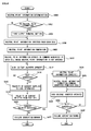
- FIG.4 is a signal flowchart illustrating an operation of a master controller according to a control method of the present invention.
- the master controller (140) first determines neutral point information set up to itself in advance in operating the high voltage inverter (S400). That is, the master controller (140) determines whether the output terminal (OL1) of the U phase unit cell (112a), the output terminal (OL1) of the V phase unit cell (114a) and the output terminal (OL1) of the W phase unit cell (116a) are set up at the neutral point (118), or the output terminal (OL2) of the U phase unit cell (112f), the output terminal (OL2) of the V phase unit cell (114f) and the output terminal (OL2) of the W phase unit cell (116f) are set up at the neutral point (118).
- the master controller (140) determines whether the neutral point information is set up (S402), and sets up the first output terminal of the high voltage inverter at the neutral point (118) if there is no information on the neutral point (S404). That is, the master controller (140) sets up the output terminal (OL1) of the U phase unit cell (112a), the output terminal (OL1) of the V phase unit cell (114a) and the output terminal (OL1) of the W phase unit cell (116a) as the neutral point (118) if no neutral point information is set up.
- the setting up of the neutral point information may be set up by neutral point information of the output terminal (OL2) of the U phase unit cell (112f), the output terminal (OL2) of the V phase unit cell (114f) and the output terminal (OL2) of the W phase unit cell (116f), which are second output terminal of the high voltage inverter.
- the master controller (140) communicates with the plurality of cell controllers (330) each disposed at the plurality of U phase unit cells (112), the plurality of V phase unit cells (114) and the plurality of W phase unit cells (116) to input the neutral point information set up at each of the plurality of U phase unit cells (112), the plurality of V phase unit cells (114) and the plurality of W phase unit cells (116).
- the master controller (140) compares the neutral point information set up to itself with the neutral point information set up at each of the plurality of U phase unit cells (112), the plurality of V phase unit cells (114) and the plurality of W phase unit cells (116) (S408).
- the master controller (140) controls the plurality of cell controllers (330) to activate the high voltage inverter (S412) and to determine whether a trip has occurred on the operating high voltage inverter (S414).
- the master controller (140) communicates with the plurality of cell controllers (330) each disposed at the plurality of U phase unit cells (112), the plurality of V phase unit cells (114) and the plurality of W phase unit cells (116) to input the polarity of current outputted by each of the plurality of cell controllers (330) each disposed at the plurality of U phase unit cells (112), the plurality of V phase unit cells (114) and the plurality of W phase unit cells (116) (S418). That is, the cell controllers (330) input the polarity of current determined by using the detection signal from the CT (320).
- the master controller (140) determines whether the polarity of current detected by using the detection signal of the CT (130) matches that inputted from the plurality of cell controllers (330) (S420).
- the master controller (140) As a result of the determination, if it is determined that polarities are matched, the master controller (140) generates a warning to end the operation, because it means that other failures than the accurate setting of the neutral point (118) have been generated.
- the master controller (140) corrects the neutral point information set up to itself, because it means that the neutral point (118) is not accurately set up (S424).
- the master controller (140) correctly sets up the output terminal (OL2) of the U phase unit cell (112f), the output terminal (OL2) of the V phase unit cell (114f) and the output terminal (OL2) of the W phase unit cell (116f) as neutral point (118), if the output terminal (OL1) of the U phase unit cell (112a), the output terminal (OL1) of the V phase unit cell (114a) and the output terminal (OL1) of the W phase unit cell (116a) are set up as the neutral point (118).
- the master controller (140) correctly sets up the output terminal (OL1) of the U phase unit cell (112a), the output terminal (OL1) of the V phase unit cell (114a) and the output terminal (OL1) of the W phase unit cell (116a) as neutral point (118), if the output terminal (OL2) of the U phase unit cell (112f), the output terminal (OL2) of the V phase unit cell (114f) and the output terminal (OL2) of the W phase unit cell (116f) are set up as neutral point (118).
- the master controller (140) communicates with the plurality of cell controllers (330) to generate a correction command to correct the neutral point information (S426).
- the master controller (140) reactivate the high voltage inverter (S428) to determine if the trip has been generated while the high voltage inverter is under operation (S430).
- the master controller (140) keep operating the high voltage inverter to drive the load (120), because it means that the master controller (140) and each of the plurality of cell controllers (330) are set up with an accurate position of neutral point (118).
- the master controller (140) As a result of the determination, if it is determined that the trip has been generated while the high voltage inverter is under operation, the master controller (140) generates a warning to end the operation, because it means that other failures than the accurate setting of the neutral point (118) have been generated.
- control device and the control method of a high voltage inverter automatically correct the wrong set-up of neutral point information, if wrong neutral point information is set up on the master controller and each cell controller of the plurality of U phase unit cells, the plurality of V phase unit cells and the plurality of W phase unit cells.
Landscapes
- Engineering & Computer Science (AREA)
- Power Engineering (AREA)
- Inverter Devices (AREA)
- Supply And Distribution Of Alternating Current (AREA)
- Control Of Ac Motors In General (AREA)
Applications Claiming Priority (1)
| Application Number | Priority Date | Filing Date | Title |
|---|---|---|---|
| KR1020090080214A KR101025647B1 (ko) | 2009-08-28 | 2009-08-28 | 고압 인버터의 제어장치 및 방법 |
Publications (3)
| Publication Number | Publication Date |
|---|---|
| EP2290800A2 true EP2290800A2 (fr) | 2011-03-02 |
| EP2290800A3 EP2290800A3 (fr) | 2015-07-29 |
| EP2290800B1 EP2290800B1 (fr) | 2017-10-25 |
Family
ID=43476782
Family Applications (1)
| Application Number | Title | Priority Date | Filing Date |
|---|---|---|---|
| EP10172227.0A Not-in-force EP2290800B1 (fr) | 2009-08-28 | 2010-08-06 | Dispositif de commande et procédé de commande d'inverseur haute tension |
Country Status (6)
| Country | Link |
|---|---|
| US (1) | US8345455B2 (fr) |
| EP (1) | EP2290800B1 (fr) |
| JP (1) | JP5192504B2 (fr) |
| KR (1) | KR101025647B1 (fr) |
| CN (1) | CN102005961B (fr) |
| ES (1) | ES2654928T3 (fr) |
Cited By (1)
| Publication number | Priority date | Publication date | Assignee | Title |
|---|---|---|---|---|
| EP2830207A3 (fr) * | 2013-07-22 | 2015-07-08 | LSIS Co., Ltd. | Onduleur multi-niveaux avec modules cellulaires à alimentation séparé |
Families Citing this family (11)
| Publication number | Priority date | Publication date | Assignee | Title |
|---|---|---|---|---|
| JP5360125B2 (ja) * | 2011-04-26 | 2013-12-04 | 株式会社安川電機 | 直列多重電力変換装置 |
| KR101707255B1 (ko) * | 2012-04-02 | 2017-02-15 | 엘에스산전 주식회사 | 고압인버터 제어방법 |
| DE102012216469A1 (de) * | 2012-09-14 | 2014-03-20 | Robert Bosch Gmbh | Energieversorgungssystem und Verfahren zum Ansteuern von Koppeleinrichtungen einer Energiespeichereinrichtung |
| US9531292B2 (en) | 2013-06-14 | 2016-12-27 | Abb Technology Ltd | Arrangement, method and computer program product concerned with tapping of power from a DC power line to an AC power line |
| EP3000165B1 (fr) * | 2013-07-08 | 2019-11-20 | Siemens Aktiengesellschaft | Convertisseur de courant à plusieurs niveaux pour la compensation de l'énergie réactive et procédé permettant de faire fonctionner ledit convertisseur |
| KR101735919B1 (ko) | 2015-06-02 | 2017-05-16 | 엘에스산전 주식회사 | 인버터 제어 방법 |
| KR102485705B1 (ko) | 2016-02-18 | 2023-01-05 | 엘에스일렉트릭(주) | 멀티 레벨 인버터의 3상 평형 전압 제어 방법 |
| JP6390806B1 (ja) * | 2017-08-02 | 2018-09-19 | 株式会社明電舎 | インバータ装置 |
| US11876438B2 (en) * | 2019-01-04 | 2024-01-16 | Innomotics Gmbh | Reducing input harmonic distortion in a power supply |
| KR20200120088A (ko) | 2019-04-11 | 2020-10-21 | 엘에스일렉트릭(주) | 트립 데이터 수정이 가능한 인버터와 이를 이용한 인버터의 트립 데이터 수정 방법 |
| CN116760304B (zh) * | 2023-08-18 | 2024-01-23 | 深圳华越南方电子技术有限公司 | 级联变频器、级联变频器的控制方法、设备和存储介质 |
Family Cites Families (18)
| Publication number | Priority date | Publication date | Assignee | Title |
|---|---|---|---|---|
| US5047910A (en) * | 1990-07-09 | 1991-09-10 | Teledyne Inet | Ideal sinusoidal voltage waveform synthesis control system |
| US5625545A (en) * | 1994-03-01 | 1997-04-29 | Halmar Robicon Group | Medium voltage PWM drive and method |
| KR100326104B1 (ko) * | 1997-08-04 | 2002-10-11 | 가부시끼가이샤 도시바 | 전력변환장치의제어방법 |
| JP3544838B2 (ja) * | 1997-10-09 | 2004-07-21 | 株式会社東芝 | 多重インバータ装置及びその制御方法 |
| US5986909A (en) * | 1998-05-21 | 1999-11-16 | Robicon Corporation | Multiphase power supply with plural series connected cells and failed cell bypass |
| JP3773794B2 (ja) | 2001-01-31 | 2006-05-10 | 東芝三菱電機産業システム株式会社 | 電力変換装置 |
| KR100738571B1 (ko) | 2003-09-29 | 2007-07-11 | 현대중공업 주식회사 | Can 통신 인터럽트를 이용한 h-브릿지 멀티레벨인버터시스템 |
| KR100993673B1 (ko) * | 2004-06-28 | 2010-11-10 | 엘지디스플레이 주식회사 | 액정표시장치의 램프 구동장치 및 방법 |
| US7508147B2 (en) * | 2005-05-19 | 2009-03-24 | Siemens Energy & Automation, Inc. | Variable-frequency drive with regeneration capability |
| JP4466618B2 (ja) * | 2006-06-28 | 2010-05-26 | 株式会社日立製作所 | 電力変換装置及び電力変換方法 |
| KR100863767B1 (ko) * | 2006-12-28 | 2008-10-16 | 현대중공업 주식회사 | H-브릿지 멀티레벨 인버터 파워 셀 고장시 레이어 단위의정격감소 연속운전 장치 및 방법 |
| KR100825323B1 (ko) * | 2007-03-05 | 2008-04-28 | 엘에스산전 주식회사 | 단위 셀 역률 동일 제어 장치를 가지는 캐스케이드 방식을이용한 멀티레벨 인버터 및 그 제어방법 |
| KR20090044126A (ko) * | 2007-10-31 | 2009-05-07 | 현대중공업 주식회사 | 에이치-브릿지 멀티레벨 인버터 삼상 불 평형 제어방법 및장치 |
| JP5230207B2 (ja) | 2008-01-07 | 2013-07-10 | 三菱重工業株式会社 | 双方向電力変換器およびその制御方法 |
| JP5266775B2 (ja) | 2008-01-31 | 2013-08-21 | 富士電機株式会社 | 電力変換装置 |
| KR20090100655A (ko) * | 2008-03-20 | 2009-09-24 | 엘에스산전 주식회사 | 멀티 레벨 인버터 |
| US7940537B2 (en) * | 2008-12-31 | 2011-05-10 | Teco-Westinghouse Motor Company | Partial regeneration in a multi-level power inverter |
| US8254076B2 (en) * | 2009-06-30 | 2012-08-28 | Teco-Westinghouse Motor Company | Providing modular power conversion |
-
2009
- 2009-08-28 KR KR1020090080214A patent/KR101025647B1/ko not_active Expired - Fee Related
-
2010
- 2010-02-22 US US12/710,295 patent/US8345455B2/en not_active Expired - Fee Related
- 2010-03-09 JP JP2010051286A patent/JP5192504B2/ja not_active Expired - Fee Related
- 2010-03-18 CN CN2010101386400A patent/CN102005961B/zh not_active Expired - Fee Related
- 2010-08-06 EP EP10172227.0A patent/EP2290800B1/fr not_active Not-in-force
- 2010-08-06 ES ES10172227.0T patent/ES2654928T3/es active Active
Non-Patent Citations (1)
| Title |
|---|
| None |
Cited By (1)
| Publication number | Priority date | Publication date | Assignee | Title |
|---|---|---|---|---|
| EP2830207A3 (fr) * | 2013-07-22 | 2015-07-08 | LSIS Co., Ltd. | Onduleur multi-niveaux avec modules cellulaires à alimentation séparé |
Also Published As
| Publication number | Publication date |
|---|---|
| KR101025647B1 (ko) | 2011-03-30 |
| JP2011050230A (ja) | 2011-03-10 |
| KR20110022787A (ko) | 2011-03-08 |
| US20110050199A1 (en) | 2011-03-03 |
| US8345455B2 (en) | 2013-01-01 |
| JP5192504B2 (ja) | 2013-05-08 |
| EP2290800B1 (fr) | 2017-10-25 |
| EP2290800A3 (fr) | 2015-07-29 |
| CN102005961B (zh) | 2013-09-18 |
| CN102005961A (zh) | 2011-04-06 |
| ES2654928T3 (es) | 2018-02-15 |
Similar Documents
| Publication | Publication Date | Title |
|---|---|---|
| EP2290800A2 (fr) | Dispositif de commande et procédé de commande d'inverseur haute tension | |
| CA2879956C (fr) | Systeme d'alimentation | |
| US10734916B2 (en) | Power conversion device | |
| US9812990B1 (en) | Spare on demand power cells for modular multilevel power converter | |
| JP5314100B2 (ja) | 電源装置 | |
| JP5864241B2 (ja) | 電力変換装置 | |
| CN111771320B (zh) | 电源装置 | |
| US20120275202A1 (en) | Series multiplex power conversion apparatus | |
| US20160190924A1 (en) | Electric power conversion device | |
| JP6525364B2 (ja) | 電力変換装置 | |
| JP5696485B2 (ja) | インバータ装置および電動機ドライブシステム | |
| JP2011010480A (ja) | 電力変換装置 | |
| JP5673114B2 (ja) | インバータ装置および電動機ドライブシステム | |
| KR102895792B1 (ko) | 전원 장치 | |
| US20130193762A1 (en) | Three-level power converting apparatus | |
| US8760890B2 (en) | Current source inverter | |
| JP2012205328A (ja) | 系統連系装置 | |
| JP5471152B2 (ja) | 電動機駆動方法 | |
| JP2015144518A (ja) | インバータ回路 | |
| KR101237363B1 (ko) | Pwm 컨버터 제어방법 | |
| JP5481055B2 (ja) | 電力変換装置 | |
| JP4831303B2 (ja) | 交流交流直接変換器の制御装置 | |
| KR20240115084A (ko) | 인버터 회로 및 모터 제어 장치 | |
| JP2021118655A (ja) | インバータ装置 | |
| KR20200054767A (ko) | 스위칭 모듈 제어 장치, 전력 변환 장치 및 이의 오동작 방지 방법 |
Legal Events
| Date | Code | Title | Description |
|---|---|---|---|
| PUAI | Public reference made under article 153(3) epc to a published international application that has entered the european phase |
Free format text: ORIGINAL CODE: 0009012 |
|
| AK | Designated contracting states |
Kind code of ref document: A2 Designated state(s): AL AT BE BG CH CY CZ DE DK EE ES FI FR GB GR HR HU IE IS IT LI LT LU LV MC MK MT NL NO PL PT RO SE SI SK SM TR |
|
| AX | Request for extension of the european patent |
Extension state: BA ME RS |
|
| PUAL | Search report despatched |
Free format text: ORIGINAL CODE: 0009013 |
|
| AK | Designated contracting states |
Kind code of ref document: A3 Designated state(s): AL AT BE BG CH CY CZ DE DK EE ES FI FR GB GR HR HU IE IS IT LI LT LU LV MC MK MT NL NO PL PT RO SE SI SK SM TR |
|
| AX | Request for extension of the european patent |
Extension state: BA ME RS |
|
| RIC1 | Information provided on ipc code assigned before grant |
Ipc: H02M 7/49 20070101AFI20150619BHEP Ipc: H02M 5/453 20060101ALI20150619BHEP |
|
| 17P | Request for examination filed |
Effective date: 20160126 |
|
| RBV | Designated contracting states (corrected) |
Designated state(s): AL AT BE BG CH CY CZ DE DK EE ES FI FR GB GR HR HU IE IS IT LI LT LU LV MC MK MT NL NO PL PT RO SE SI SK SM TR |
|
| GRAP | Despatch of communication of intention to grant a patent |
Free format text: ORIGINAL CODE: EPIDOSNIGR1 |
|
| INTG | Intention to grant announced |
Effective date: 20170608 |
|
| GRAS | Grant fee paid |
Free format text: ORIGINAL CODE: EPIDOSNIGR3 |
|
| GRAA | (expected) grant |
Free format text: ORIGINAL CODE: 0009210 |
|
| AK | Designated contracting states |
Kind code of ref document: B1 Designated state(s): AL AT BE BG CH CY CZ DE DK EE ES FI FR GB GR HR HU IE IS IT LI LT LU LV MC MK MT NL NO PL PT RO SE SI SK SM TR |
|
| REG | Reference to a national code |
Ref country code: GB Ref legal event code: FG4D |
|
| REG | Reference to a national code |
Ref country code: CH Ref legal event code: EP |
|
| REG | Reference to a national code |
Ref country code: AT Ref legal event code: REF Ref document number: 940780 Country of ref document: AT Kind code of ref document: T Effective date: 20171115 |
|
| REG | Reference to a national code |
Ref country code: IE Ref legal event code: FG4D |
|
| REG | Reference to a national code |
Ref country code: DE Ref legal event code: R096 Ref document number: 602010046154 Country of ref document: DE |
|
| REG | Reference to a national code |
Ref country code: ES Ref legal event code: FG2A Ref document number: 2654928 Country of ref document: ES Kind code of ref document: T3 Effective date: 20180215 |
|
| REG | Reference to a national code |
Ref country code: NL Ref legal event code: MP Effective date: 20171025 |
|
| REG | Reference to a national code |
Ref country code: LT Ref legal event code: MG4D |
|
| REG | Reference to a national code |
Ref country code: AT Ref legal event code: MK05 Ref document number: 940780 Country of ref document: AT Kind code of ref document: T Effective date: 20171025 |
|
| PG25 | Lapsed in a contracting state [announced via postgrant information from national office to epo] |
Ref country code: NL Free format text: LAPSE BECAUSE OF FAILURE TO SUBMIT A TRANSLATION OF THE DESCRIPTION OR TO PAY THE FEE WITHIN THE PRESCRIBED TIME-LIMIT Effective date: 20171025 |
|
| PG25 | Lapsed in a contracting state [announced via postgrant information from national office to epo] |
Ref country code: SE Free format text: LAPSE BECAUSE OF FAILURE TO SUBMIT A TRANSLATION OF THE DESCRIPTION OR TO PAY THE FEE WITHIN THE PRESCRIBED TIME-LIMIT Effective date: 20171025 Ref country code: LT Free format text: LAPSE BECAUSE OF FAILURE TO SUBMIT A TRANSLATION OF THE DESCRIPTION OR TO PAY THE FEE WITHIN THE PRESCRIBED TIME-LIMIT Effective date: 20171025 Ref country code: FI Free format text: LAPSE BECAUSE OF FAILURE TO SUBMIT A TRANSLATION OF THE DESCRIPTION OR TO PAY THE FEE WITHIN THE PRESCRIBED TIME-LIMIT Effective date: 20171025 Ref country code: NO Free format text: LAPSE BECAUSE OF FAILURE TO SUBMIT A TRANSLATION OF THE DESCRIPTION OR TO PAY THE FEE WITHIN THE PRESCRIBED TIME-LIMIT Effective date: 20180125 |
|
| PG25 | Lapsed in a contracting state [announced via postgrant information from national office to epo] |
Ref country code: LV Free format text: LAPSE BECAUSE OF FAILURE TO SUBMIT A TRANSLATION OF THE DESCRIPTION OR TO PAY THE FEE WITHIN THE PRESCRIBED TIME-LIMIT Effective date: 20171025 Ref country code: HR Free format text: LAPSE BECAUSE OF FAILURE TO SUBMIT A TRANSLATION OF THE DESCRIPTION OR TO PAY THE FEE WITHIN THE PRESCRIBED TIME-LIMIT Effective date: 20171025 Ref country code: GR Free format text: LAPSE BECAUSE OF FAILURE TO SUBMIT A TRANSLATION OF THE DESCRIPTION OR TO PAY THE FEE WITHIN THE PRESCRIBED TIME-LIMIT Effective date: 20180126 Ref country code: IS Free format text: LAPSE BECAUSE OF FAILURE TO SUBMIT A TRANSLATION OF THE DESCRIPTION OR TO PAY THE FEE WITHIN THE PRESCRIBED TIME-LIMIT Effective date: 20180225 Ref country code: BG Free format text: LAPSE BECAUSE OF FAILURE TO SUBMIT A TRANSLATION OF THE DESCRIPTION OR TO PAY THE FEE WITHIN THE PRESCRIBED TIME-LIMIT Effective date: 20180125 Ref country code: AT Free format text: LAPSE BECAUSE OF FAILURE TO SUBMIT A TRANSLATION OF THE DESCRIPTION OR TO PAY THE FEE WITHIN THE PRESCRIBED TIME-LIMIT Effective date: 20171025 |
|
| REG | Reference to a national code |
Ref country code: FR Ref legal event code: PLFP Year of fee payment: 9 |
|
| REG | Reference to a national code |
Ref country code: DE Ref legal event code: R097 Ref document number: 602010046154 Country of ref document: DE |
|
| PG25 | Lapsed in a contracting state [announced via postgrant information from national office to epo] |
Ref country code: CZ Free format text: LAPSE BECAUSE OF FAILURE TO SUBMIT A TRANSLATION OF THE DESCRIPTION OR TO PAY THE FEE WITHIN THE PRESCRIBED TIME-LIMIT Effective date: 20171025 Ref country code: SK Free format text: LAPSE BECAUSE OF FAILURE TO SUBMIT A TRANSLATION OF THE DESCRIPTION OR TO PAY THE FEE WITHIN THE PRESCRIBED TIME-LIMIT Effective date: 20171025 Ref country code: DK Free format text: LAPSE BECAUSE OF FAILURE TO SUBMIT A TRANSLATION OF THE DESCRIPTION OR TO PAY THE FEE WITHIN THE PRESCRIBED TIME-LIMIT Effective date: 20171025 Ref country code: CY Free format text: LAPSE BECAUSE OF FAILURE TO SUBMIT A TRANSLATION OF THE DESCRIPTION OR TO PAY THE FEE WITHIN THE PRESCRIBED TIME-LIMIT Effective date: 20171025 Ref country code: EE Free format text: LAPSE BECAUSE OF FAILURE TO SUBMIT A TRANSLATION OF THE DESCRIPTION OR TO PAY THE FEE WITHIN THE PRESCRIBED TIME-LIMIT Effective date: 20171025 |
|
| PG25 | Lapsed in a contracting state [announced via postgrant information from national office to epo] |
Ref country code: RO Free format text: LAPSE BECAUSE OF FAILURE TO SUBMIT A TRANSLATION OF THE DESCRIPTION OR TO PAY THE FEE WITHIN THE PRESCRIBED TIME-LIMIT Effective date: 20171025 Ref country code: PL Free format text: LAPSE BECAUSE OF FAILURE TO SUBMIT A TRANSLATION OF THE DESCRIPTION OR TO PAY THE FEE WITHIN THE PRESCRIBED TIME-LIMIT Effective date: 20171025 Ref country code: SM Free format text: LAPSE BECAUSE OF FAILURE TO SUBMIT A TRANSLATION OF THE DESCRIPTION OR TO PAY THE FEE WITHIN THE PRESCRIBED TIME-LIMIT Effective date: 20171025 |
|
| PLBE | No opposition filed within time limit |
Free format text: ORIGINAL CODE: 0009261 |
|
| STAA | Information on the status of an ep patent application or granted ep patent |
Free format text: STATUS: NO OPPOSITION FILED WITHIN TIME LIMIT |
|
| 26N | No opposition filed |
Effective date: 20180726 |
|
| PG25 | Lapsed in a contracting state [announced via postgrant information from national office to epo] |
Ref country code: SI Free format text: LAPSE BECAUSE OF FAILURE TO SUBMIT A TRANSLATION OF THE DESCRIPTION OR TO PAY THE FEE WITHIN THE PRESCRIBED TIME-LIMIT Effective date: 20171025 |
|
| PG25 | Lapsed in a contracting state [announced via postgrant information from national office to epo] |
Ref country code: MC Free format text: LAPSE BECAUSE OF FAILURE TO SUBMIT A TRANSLATION OF THE DESCRIPTION OR TO PAY THE FEE WITHIN THE PRESCRIBED TIME-LIMIT Effective date: 20171025 |
|
| REG | Reference to a national code |
Ref country code: CH Ref legal event code: PL |
|
| PG25 | Lapsed in a contracting state [announced via postgrant information from national office to epo] |
Ref country code: CH Free format text: LAPSE BECAUSE OF NON-PAYMENT OF DUE FEES Effective date: 20180831 Ref country code: LI Free format text: LAPSE BECAUSE OF NON-PAYMENT OF DUE FEES Effective date: 20180831 Ref country code: LU Free format text: LAPSE BECAUSE OF NON-PAYMENT OF DUE FEES Effective date: 20180806 |
|
| REG | Reference to a national code |
Ref country code: BE Ref legal event code: MM Effective date: 20180831 |
|
| REG | Reference to a national code |
Ref country code: IE Ref legal event code: MM4A |
|
| PG25 | Lapsed in a contracting state [announced via postgrant information from national office to epo] |
Ref country code: IE Free format text: LAPSE BECAUSE OF NON-PAYMENT OF DUE FEES Effective date: 20180806 |
|
| PG25 | Lapsed in a contracting state [announced via postgrant information from national office to epo] |
Ref country code: BE Free format text: LAPSE BECAUSE OF NON-PAYMENT OF DUE FEES Effective date: 20180831 |
|
| PG25 | Lapsed in a contracting state [announced via postgrant information from national office to epo] |
Ref country code: MT Free format text: LAPSE BECAUSE OF NON-PAYMENT OF DUE FEES Effective date: 20180806 |
|
| PG25 | Lapsed in a contracting state [announced via postgrant information from national office to epo] |
Ref country code: TR Free format text: LAPSE BECAUSE OF FAILURE TO SUBMIT A TRANSLATION OF THE DESCRIPTION OR TO PAY THE FEE WITHIN THE PRESCRIBED TIME-LIMIT Effective date: 20171025 |
|
| PG25 | Lapsed in a contracting state [announced via postgrant information from national office to epo] |
Ref country code: HU Free format text: LAPSE BECAUSE OF FAILURE TO SUBMIT A TRANSLATION OF THE DESCRIPTION OR TO PAY THE FEE WITHIN THE PRESCRIBED TIME-LIMIT; INVALID AB INITIO Effective date: 20100806 Ref country code: PT Free format text: LAPSE BECAUSE OF FAILURE TO SUBMIT A TRANSLATION OF THE DESCRIPTION OR TO PAY THE FEE WITHIN THE PRESCRIBED TIME-LIMIT Effective date: 20171025 |
|
| PG25 | Lapsed in a contracting state [announced via postgrant information from national office to epo] |
Ref country code: MK Free format text: LAPSE BECAUSE OF NON-PAYMENT OF DUE FEES Effective date: 20171025 |
|
| PG25 | Lapsed in a contracting state [announced via postgrant information from national office to epo] |
Ref country code: AL Free format text: LAPSE BECAUSE OF FAILURE TO SUBMIT A TRANSLATION OF THE DESCRIPTION OR TO PAY THE FEE WITHIN THE PRESCRIBED TIME-LIMIT Effective date: 20171025 |
|
| PGFP | Annual fee paid to national office [announced via postgrant information from national office to epo] |
Ref country code: FR Payment date: 20200609 Year of fee payment: 11 |
|
| PG25 | Lapsed in a contracting state [announced via postgrant information from national office to epo] |
Ref country code: FR Free format text: LAPSE BECAUSE OF NON-PAYMENT OF DUE FEES Effective date: 20210831 |
|
| PGFP | Annual fee paid to national office [announced via postgrant information from national office to epo] |
Ref country code: IT Payment date: 20220606 Year of fee payment: 13 Ref country code: GB Payment date: 20220607 Year of fee payment: 13 |
|
| PGFP | Annual fee paid to national office [announced via postgrant information from national office to epo] |
Ref country code: ES Payment date: 20220908 Year of fee payment: 13 Ref country code: DE Payment date: 20220603 Year of fee payment: 13 |
|
| REG | Reference to a national code |
Ref country code: DE Ref legal event code: R119 Ref document number: 602010046154 Country of ref document: DE |
|
| GBPC | Gb: european patent ceased through non-payment of renewal fee |
Effective date: 20230806 |
|
| PG25 | Lapsed in a contracting state [announced via postgrant information from national office to epo] |
Ref country code: GB Free format text: LAPSE BECAUSE OF NON-PAYMENT OF DUE FEES Effective date: 20230806 |
|
| PG25 | Lapsed in a contracting state [announced via postgrant information from national office to epo] |
Ref country code: IT Free format text: LAPSE BECAUSE OF NON-PAYMENT OF DUE FEES Effective date: 20230806 Ref country code: GB Free format text: LAPSE BECAUSE OF NON-PAYMENT OF DUE FEES Effective date: 20230806 Ref country code: DE Free format text: LAPSE BECAUSE OF NON-PAYMENT OF DUE FEES Effective date: 20240301 |
|
| REG | Reference to a national code |
Ref country code: ES Ref legal event code: FD2A Effective date: 20240927 |
|
| PG25 | Lapsed in a contracting state [announced via postgrant information from national office to epo] |
Ref country code: ES Free format text: LAPSE BECAUSE OF NON-PAYMENT OF DUE FEES Effective date: 20230807 |
|
| PG25 | Lapsed in a contracting state [announced via postgrant information from national office to epo] |
Ref country code: ES Free format text: LAPSE BECAUSE OF NON-PAYMENT OF DUE FEES Effective date: 20230807 |