EP2290933B1 - Mobiles Endgerät mit Solarzelle und einer Vielzahl von Leuchtelementen - Google Patents
Mobiles Endgerät mit Solarzelle und einer Vielzahl von Leuchtelementen Download PDFInfo
- Publication number
- EP2290933B1 EP2290933B1 EP10169999.9A EP10169999A EP2290933B1 EP 2290933 B1 EP2290933 B1 EP 2290933B1 EP 10169999 A EP10169999 A EP 10169999A EP 2290933 B1 EP2290933 B1 EP 2290933B1
- Authority
- EP
- European Patent Office
- Prior art keywords
- luminous elements
- terminal
- solar cell
- luminous
- mobile terminal
- Prior art date
- Legal status (The legal status is an assumption and is not a legal conclusion. Google has not performed a legal analysis and makes no representation as to the accuracy of the status listed.)
- Not-in-force
Links
Images




Classifications
-
- H—ELECTRICITY
- H04—ELECTRIC COMMUNICATION TECHNIQUE
- H04M—TELEPHONIC COMMUNICATION
- H04M1/00—Substation equipment, e.g. for use by subscribers
- H04M1/02—Constructional features of telephone sets
- H04M1/22—Illumination; Arrangements for improving the visibility of characters on dials
-
- G—PHYSICS
- G06—COMPUTING OR CALCULATING; COUNTING
- G06F—ELECTRIC DIGITAL DATA PROCESSING
- G06F3/00—Input arrangements for transferring data to be processed into a form capable of being handled by the computer; Output arrangements for transferring data from processing unit to output unit, e.g. interface arrangements
- G06F3/01—Input arrangements or combined input and output arrangements for interaction between user and computer
- G06F3/03—Arrangements for converting the position or the displacement of a member into a coded form
- G06F3/041—Digitisers, e.g. for touch screens or touch pads, characterised by the transducing means
-
- H—ELECTRICITY
- H04—ELECTRIC COMMUNICATION TECHNIQUE
- H04M—TELEPHONIC COMMUNICATION
- H04M1/00—Substation equipment, e.g. for use by subscribers
- H04M1/72—Mobile telephones; Cordless telephones, i.e. devices for establishing wireless links to base stations without route selection
- H04M1/724—User interfaces specially adapted for cordless or mobile telephones
- H04M1/72403—User interfaces specially adapted for cordless or mobile telephones with means for local support of applications that increase the functionality
- H04M1/72427—User interfaces specially adapted for cordless or mobile telephones with means for local support of applications that increase the functionality for supporting games or graphical animations
-
- H—ELECTRICITY
- H04—ELECTRIC COMMUNICATION TECHNIQUE
- H04W—WIRELESS COMMUNICATION NETWORKS
- H04W52/00—Power management, e.g. Transmission Power Control [TPC] or power classes
- H04W52/02—Power saving arrangements
- H04W52/0209—Power saving arrangements in terminal devices
- H04W52/0261—Power saving arrangements in terminal devices managing power supply demand, e.g. depending on battery level
- H04W52/0267—Power saving arrangements in terminal devices managing power supply demand, e.g. depending on battery level by controlling user interface components
- H04W52/027—Power saving arrangements in terminal devices managing power supply demand, e.g. depending on battery level by controlling user interface components by controlling a display operation or backlight unit
-
- H—ELECTRICITY
- H02—GENERATION; CONVERSION OR DISTRIBUTION OF ELECTRIC POWER
- H02J—ELECTRIC POWER NETWORKS; CIRCUIT ARRANGEMENTS OR SYSTEMS FOR SUPPLYING OR DISTRIBUTING ELECTRIC POWER; SYSTEMS FOR STORING ELECTRIC ENERGY
- H02J7/00—Circuit arrangements for charging or discharging batteries or for supplying loads from batteries
- H02J7/34—Parallel operation in networks using both storage and other DC sources, e.g. providing buffering
- H02J7/35—Parallel operation in networks using both storage and other DC sources, e.g. providing buffering with light sensitive cells
-
- H—ELECTRICITY
- H04—ELECTRIC COMMUNICATION TECHNIQUE
- H04M—TELEPHONIC COMMUNICATION
- H04M1/00—Substation equipment, e.g. for use by subscribers
- H04M1/02—Constructional features of telephone sets
- H04M1/0202—Portable telephone sets, e.g. cordless phones, mobile phones or bar type handsets
- H04M1/0206—Portable telephones comprising a plurality of mechanically joined movable body parts, e.g. hinged housings
- H04M1/0208—Portable telephones comprising a plurality of mechanically joined movable body parts, e.g. hinged housings characterized by the relative motions of the body parts
- H04M1/0214—Foldable telephones, i.e. with body parts pivoting to an open position around an axis parallel to the plane they define in closed position
-
- H—ELECTRICITY
- H04—ELECTRIC COMMUNICATION TECHNIQUE
- H04M—TELEPHONIC COMMUNICATION
- H04M1/00—Substation equipment, e.g. for use by subscribers
- H04M1/02—Constructional features of telephone sets
- H04M1/0202—Portable telephone sets, e.g. cordless phones, mobile phones or bar type handsets
- H04M1/026—Details of the structure or mounting of specific components
- H04M1/0266—Details of the structure or mounting of specific components for a display module assembly
-
- H—ELECTRICITY
- H04—ELECTRIC COMMUNICATION TECHNIQUE
- H04M—TELEPHONIC COMMUNICATION
- H04M1/00—Substation equipment, e.g. for use by subscribers
- H04M1/57—Arrangements for indicating or recording the number of the calling subscriber at the called subscriber's set
- H04M1/575—Means for retrieving and displaying personal data about calling party
-
- H—ELECTRICITY
- H04—ELECTRIC COMMUNICATION TECHNIQUE
- H04M—TELEPHONIC COMMUNICATION
- H04M2250/00—Details of telephonic subscriber devices
- H04M2250/12—Details of telephonic subscriber devices including a sensor for measuring a physical value, e.g. temperature or motion
-
- H—ELECTRICITY
- H04—ELECTRIC COMMUNICATION TECHNIQUE
- H04M—TELEPHONIC COMMUNICATION
- H04M2250/00—Details of telephonic subscriber devices
- H04M2250/16—Details of telephonic subscriber devices including more than one display unit
-
- H—ELECTRICITY
- H04—ELECTRIC COMMUNICATION TECHNIQUE
- H04M—TELEPHONIC COMMUNICATION
- H04M2250/00—Details of telephonic subscriber devices
- H04M2250/22—Details of telephonic subscriber devices including a touch pad, a touch sensor or a touch detector
-
- Y—GENERAL TAGGING OF NEW TECHNOLOGICAL DEVELOPMENTS; GENERAL TAGGING OF CROSS-SECTIONAL TECHNOLOGIES SPANNING OVER SEVERAL SECTIONS OF THE IPC; TECHNICAL SUBJECTS COVERED BY FORMER USPC CROSS-REFERENCE ART COLLECTIONS [XRACs] AND DIGESTS
- Y02—TECHNOLOGIES OR APPLICATIONS FOR MITIGATION OR ADAPTATION AGAINST CLIMATE CHANGE
- Y02D—CLIMATE CHANGE MITIGATION TECHNOLOGIES IN INFORMATION AND COMMUNICATION TECHNOLOGIES [ICT], I.E. INFORMATION AND COMMUNICATION TECHNOLOGIES AIMING AT THE REDUCTION OF THEIR OWN ENERGY USE
- Y02D30/00—Reducing energy consumption in communication networks
- Y02D30/70—Reducing energy consumption in communication networks in wireless communication networks
-
- Y—GENERAL TAGGING OF NEW TECHNOLOGICAL DEVELOPMENTS; GENERAL TAGGING OF CROSS-SECTIONAL TECHNOLOGIES SPANNING OVER SEVERAL SECTIONS OF THE IPC; TECHNICAL SUBJECTS COVERED BY FORMER USPC CROSS-REFERENCE ART COLLECTIONS [XRACs] AND DIGESTS
- Y02—TECHNOLOGIES OR APPLICATIONS FOR MITIGATION OR ADAPTATION AGAINST CLIMATE CHANGE
- Y02E—REDUCTION OF GREENHOUSE GAS [GHG] EMISSIONS, RELATED TO ENERGY GENERATION, TRANSMISSION OR DISTRIBUTION
- Y02E10/00—Energy generation through renewable energy sources
- Y02E10/50—Photovoltaic [PV] energy
- Y02E10/56—Power conversion systems, e.g. maximum power point trackers
Definitions
- the present invention relates to a mobile terminal having a solar cell.
- Terminals may be divided into mobile/portable terminals and stationary terminals according to their mobility. Also, the portable terminals may be categorized into a handheld terminal and a vehicle mount terminal according to whether it is directly portable by a user.
- the terminal can be allowed to capture still images or moving images, play music or video files, play games, receive broadcast and the like, so as to be implemented as an integrated multimedia player.
- Improvement may be considered for structures and/or software of terminals in order to support and implement such complicated functions.
- the document US 2005/0117096 discloses a color display and a solar cell device including a transparent light source located behind a liquid crystal display that includes a switchable transflector layer.
- the document US 2003/0081158 discloses a device comprising a display and a solar cell.
- the document US 2008/0094025 discloses a method for arranging and connecting a plurality of solar cells on a portable device.
- an object of the present invention is to provide a mobile terminal having a solar cell, which allows a space having the solar cell to be utilized as a display space of visual information, thereby improving the spatial usability.
- Mobile terminals described in the present invention may include mobile phones, smart phones, laptop computers, digital broadcasting terminals, personal digital assistants (PDAs), portable multimedia players (PMPs), navigators, and the like.
- PDAs personal digital assistants
- PMPs portable multimedia players
- navigators and the like.
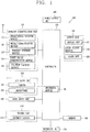
- FIG. 1 is a block diagram of a mobile terminal in accordance with one exemplary embodiment of the present invention.
- the mobile terminal 100 may comprise components, such as a wireless communication unit 110, an Audio/Video (A/V) input unit 120, a user input unit 130, a sensing unit 140, an output unit 150, a memory 160, an interface unit 170, a controller 180, a power supply unit 190 and the like.
- FIG. 1 shows the mobile terminal 100 having various components, but it is understood that implementing all of the illustrated components is not a requirement. Greater or fewer components may alternatively be implemented.
- the wireless communication unit 110 may typically include one or more components which permit wireless communications between the portable terminal 100 and a wireless communication system or between the portable terminal 100 and a network within which the portable terminal 100 is located.
- the wireless communication unit 110 may include a broadcast receiving module 111, a mobile communication module 112, a wireless internet module 113, a short-range communication module 114, a position location module 115 and the like.
- the broadcast receiving module 111 receives a broadcast signal and/or broadcast associated information from an external broadcast managing entity via a broadcast channel.
- the broadcast channel may include a satellite channel and a terrestrial channel.
- the broadcast managing entity may indicate a server which generates and transmits a broadcast signal and/or broadcast associated information or a server which receives a pre-generated broadcast signal and/or broadcast associated information and sends them to the portable terminal.
- the broadcast signal may be implemented as a TV broadcast signal, a radio broadcast signal, and a data broadcast signal, among others.
- the broadcast signal may further include a data broadcast signal combined with a TV or radio broadcast signal.
- the broadcast associated information may indicate information relating to broadcast channels, broadcast programs or broadcast service providers. Further, the broadcast associated information may be provided via a mobile communication network and received by the mobile communication module 112.
- broadcast associated information may be implemented in various formats.
- broadcast associated information may include Electronic Program Guide (EPG) of Digital Multimedia Broadcasting (DMB), Electronic Service Guide (ESG) of Digital Video Broadcast-Handheld (DVB-H), and the like.
- EPG Electronic Program Guide
- DMB Digital Multimedia Broadcasting
- ESG Electronic Service Guide
- DVD-H Digital Video Broadcast-Handheld
- the broadcast receiving module 111 may be configured to receive digital broadcast signals transmitted from various types of broadcast systems. Such broadcast systems may include Digital Multimedia Broadcasting-Terrestrial (DMB-T), Digital Multimedia Broadcasting-Satellite (DMB-S), Media Forward Link Only (MediaFLO), Digital Video Broadcast-Handheld (DVB-H), Integrated Services Digital Broadcast-Terrestrial (ISDB-T), and the like.
- the broadcast receiving module 111 may be configured to be suitable for every broadcast system transmitting broadcast signals as well as the digital broadcasting systems.
- Broadcast signals and/or broadcast associated information received via the broadcast receiving module 111 may be stored in a suitable device, such as a memory 160.
- the mobile communication module 112 transmits/receives wireless signals to/from at least one of network entities (e.g., base station, an external terminal, a server, etc.) on a mobile communication network.
- the wireless signals may include audio call signal, video call signal, or various formats of data according to transmission/reception of text/multimedia messages.
- the wireless internet module 113 supports wireless Internet access for the portable terminal. This module may be internally or externally coupled to the portable terminal 100. Examples of such wireless Internet access may include Wireless LAN (WLAN) (Wi-Fi), Wireless Broadband (Wibro), World Interoperability for Microwave Access (Wimax), High Speed Downlink Packet Access (HSDPA), and the like.
- WLAN Wireless LAN
- Wibro Wireless Broadband
- Wimax World Interoperability for Microwave Access
- HSDPA High Speed Downlink Packet Access
- the short-range communication module 114 denotes a module for short-range communications. Suitable technologies for implementing this module may include BLUETOOTH, Radio Frequency IDentification (RFID), Infrared Data Association (IrDA), Ultra-WideBand (UWB), ZigBee, and the like.
- RFID Radio Frequency IDentification
- IrDA Infrared Data Association
- UWB Ultra-WideBand
- ZigBee ZigBee
- the position location module 115 denotes a module for detecting or calculating a position of a portable terminal.
- An example of the position location module 115 may include a Global Position System (GPS) module.
- GPS Global Position System
- the A/V input unit 120 is configured to provide audio or video signal input to the mobile terminal.
- the A/V input unit 120 may include a camera 121 and a microphone 122.
- the camera 121 receives and processes image frames of still pictures or video obtained by image sensors in a video (telephony) call mode or a capturing mode.
- the processed image frames may be displayed on a display unit 151.
- the image frames processed by the camera 121 may be stored in the memory 160 or transmitted to the exterior via the wireless communication unit 110. Two or more cameras 121 may be provided according to the configuration of the mobile terminal.
- the microphone 122 may receive an external audio signal while the mobile terminal is in a particular mode, such as a phone call mode, a recording mode, a voice recognition mode, or the like. This audio signal is processed into digital data. The processed digital data is converted for output into a format transmittable to a mobile communication base station via the mobile communication module 112 in case of the phone call mode.
- the microphone 122 may include assorted noise removing algorithms to remove noise generated in the course of receiving the external audio signal.
- the user input unit 130 may generate input data input by a user to control the operation of the mobile terminal.
- the user input unit 130 may include a keypad, a dome switch, a touchpad (e.g., static pressure/capacitance), a jog wheel, a jog switch and the like.
- the sensing unit 140 provides status measurements of various aspects of the mobile terminal. For instance, the sensing unit 140 may detect an open/close status of the mobile terminal, a change in a location of the mobile terminal 100, a presence or absence of user contact with the mobile terminal 100, the orientation of the mobile terminal 100, acceleration/deceleration of the mobile terminal 100, and the like, so as to generate a sensing signal for controlling the operation of the mobile terminal 100. For example, regarding a slide-type mobile terminal, the sensing unit 140 may sense whether a sliding portion of the mobile terminal is open or closed.
- sensing functions such as the sensing unit 140 sensing the presence or absence of power provided by the power supply 190, the presence or absence of a coupling or other connection between the interface unit 170 and an external device and the like.
- the sensing unit 140 may include a proximity sensor 141.
- the output unit 150 is configured to output an audio signal, a video signal or an alarm signal.
- the output unit 150 may include a display unit 151, an audio output module 152, an alarm 153, a haptic module 154 and the like.
- the display unit 151 may output information processed in the mobile terminal 100. For example, when the mobile terminal is operating in a phone call mode, the display unit 151 will provide a User Interface (UI) or a Graphic User Interface (GUI) which includes information associated with the call. As another example, if the mobile terminal is in a video call mode or a capturing mode, the display unit 151 may additionally or alternatively display images captured and/or received, Ul, or GUI.
- UI User Interface
- GUI Graphic User Interface
- the display unit 151 may be implemented using, for example, a Liquid Crystal Display (LCD), a Thin Film Transistor-Liquid Crystal Display (TFT-LCD), an Organic Light-Emitting Diode (OLED), a flexible display, a three-dimensional (3D) display, or the like.
- LCD Liquid Crystal Display
- TFT-LCD Thin Film Transistor-Liquid Crystal Display
- OLED Organic Light-Emitting Diode
- flexible display a three-dimensional (3D) display, or the like.
- Some of the displays can be configured to be transparent such that it is possible to see the exterior therethrough. These displays may be called transparent displays.
- a representative example of the transparent display may include a Transparent Organic Light Emitting Diode (TOLED), and the like.
- the rear surface of the display unit 151 may also be implemented to be optically transparent. Under this configuration, a user can view an object positioned at a rear side of a terminal body through a region occupied by the display unit 151 of the terminal body.
- the display unit 151 may be implemented in two or more in number according to a configured aspect of the mobile terminal 100. For instance, a plurality of the display units 151 may be arranged on one surface to be spaced apart from or integrated with each other, or may be arranged on different surfaces.
- the display unit 151 and a touch sensitive sensor have a layered structure therebetween, the structure may be referred to as 'touch screen'.
- the display unit 151 may be used as an input device rather than an output device.
- the touch sensor may be implemented as a touch film, a touch sheet, a touch pad, and the like.
- the touch sensor may be configured to convert changes of a pressure applied to a specific part of the display unit 151, or a capacitance occurring from a specific part of the display unit 151, into electric input signals. Also, the touch sensor may be configured to sense not only a touched position and a touched area, but also a touch pressure.
- touch controller When touch inputs are sensed by the touch sensors, corresponding signals are transmitted to a touch controller (not shown).
- the touch controller processes the received signals, and then transmits corresponding data to the controller 180. Accordingly, the controller 180 may sense which region of the display unit 151 has been touched.
- a proximity sensor 141 may be arranged at an inner region of the mobile terminal 100 covered by the touch screen, or near the touch screen.
- the proximity sensor 141 indicates a sensor to sense presence or absence of an object approaching to a surface to be sensed, or an object disposed near a surface to be sensed, by using an electromagnetic field or infrared rays without a mechanical contact.
- the proximity sensor 141 has a longer lifespan and a more enhanced utility than a contact sensor.
- the proximity sensor 141 may include a transmissive type photoelectric sensor, a direct reflective type photoelectric sensor, a mirror reflective type photoelectric sensor, a highfrequency oscillation proximity sensor, a capacitance type proximity sensor, a magnetic type proximity sensor, an infrared rays proximity sensor, and so on.
- a capacitance type proximity sensor When the touch screen is implemented as a capacitance type, proximity of a pointer to the touch screen is sensed by changes of an electromagnetic field.
- the touch screen may be categorized into a proximity sensor.
- a status that the pointer is positioned to be proximate onto the touch screen without contact will be referred to as 'proximity touch'
- a status that the pointer substantially comes in contact with the touch screen will be referred to as 'contact touch'.
- 'proximity touch' a status that the pointer substantially comes in contact with the touch screen.
- the proximity sensor 141 senses proximity touch, and proximity touch patterns (e.g., distance, direction, speed, time, position, moving status, etc.). Information relating to the sensed proximity touch and the sensed proximity touch patterns may be output onto the touch screen.
- proximity touch patterns e.g., distance, direction, speed, time, position, moving status, etc.
- the audio output module 152 may output audio data received from the wireless communication unit 110 or stored in the memory 160, in a call-receiving mode, a call-placing mode, a recording mode, a voice recognition mode, a broadcast reception mode, and so on.
- the audio output module 152 may output audio signals relating to functions performed in the mobile terminal 100, e.g., sound alarming a call received or a message received, and so on.
- the audio output module 152 may include a receiver, a speaker, a buzzer, and so on.
- the alarm 153 outputs signals notifying occurrence of events from the mobile terminal 100.
- the events occurring from the mobile terminal 100 may include call received, message received, key signal input, touch input, and so on.
- the alarm 153 may output not only video or audio signals, but also other types of signals such as signals notifying occurrence of events in a vibration manner. Since the video or audio signals can be output through the display unit 151 or the audio output unit 152, the display unit 151 and the audio output module 152 may be categorized into a part of the alarm 153.
- the haptic module 154 generates various tactile effects which a user can feel.
- a representative example of the tactile effects generated by the haptic module 154 includes vibration.
- Vibration generated by the haptic module 154 may have a controllable intensity, a controllable pattern, and so on. For instance, different vibration may be output in a synthesized manner or in a sequential manner.
- the haptic module 154 may generate various tactile effects, including not only vibration, but also arrangement of pins vertically moving with respect to a skin being touched (contacted), air injection force or air suction force through an injection hole or a suction hole, touch by a skin surface, presence or absence of contact with an electrode, effects by stimulus such as an electrostatic force, reproduction of cold or hot feeling using a heat absorbing device or a heat emitting device, and the like.
- the haptic module 154 may be configured to transmit tactile effects (signals) through a user's direct contact, or a user's muscular sense using a finger or a hand.
- the haptic module 154 may be implemented in two or more in number according to the configuration of the mobile terminal 100.
- the memory 160 may store a program for the processing and control of the controller 180. Alternatively, the memory 160 may temporarily store input/output data (e.g., phonebook data, messages, still images, video and the like). Also, the memory 160 may store data related to various patterns of vibrations and audio output upon the touch input on the touch screen.
- input/output data e.g., phonebook data, messages, still images, video and the like.
- the memory 160 may store data related to various patterns of vibrations and audio output upon the touch input on the touch screen.
- the memory 160 may be implemented using any type of suitable storage medium including a flash memory type, a hard disk type, a multimedia card micro type, a memory card type (e.g., SD or DX memory), Random Access Memory (RAM), Static Random Access Memory (SRAM), Read-Only Memory (ROM), Electrically Erasable Programmable Read-only Memory (EEPROM), Programmable Read-only Memory (PROM), magnetic memory, magnetic disk, optical disk, and the like.
- the mobile terminal 100 may operate a web storage which performs the storage function of the memory 160 on the Internet.
- the interface unit 170 may generally be implemented to interface the mobile terminal with external devices.
- the interface unit 170 may allow a data reception from an external device, a power delivery to each component in the mobile terminal 100, or a data transmission from the mobile terminal 100 to an external device.
- the interface unit 170 may include, for example, wired/wireless headset ports, external charger ports, wired/wireless data ports, memory card ports, ports for coupling devices having an identification module, audio Input/Output (I/O) ports, video I/O ports, earphone ports, and the like.
- I/O audio Input/Output
- the identification module may be configured as a chip for storing various information required to authenticate an authority to use the mobile terminal 100, which may include a User Identity Module (UIM), a Subscriber Identity Module (SIM), and the like. Also, the device having the identification module (hereinafter, referred to as 'identification device') may be implemented in a type of smart card. Hence, the identification device can be coupled to the mobile terminal 100 via a port.
- UIM User Identity Module
- SIM Subscriber Identity Module
- the interface unit 170 may serve as a path for power to be supplied from an external cradle to the mobile terminal 100 when the mobile terminal 100 is connected to the external cradle or as a path for transferring various command signals inputted from the cradle by a user to the mobile terminal 100.
- Such various command signals or power inputted from the cradle may operate as signals for recognizing that the mobile terminal 100 has accurately been mounted to the cradle.
- the controller 180 typically controls the overall operations of the mobile terminal 100. For example, the controller 180 performs the control and processing associated with telephony calls, data communications, video calls, and the like.
- the controller 180 may include a multimedia module 181 which provides multimedia playback.
- the multimedia module 181 may be configured as part of the controller 180 or as a separate component.
- the controller 180 can perform a pattern recognition processing so as to recognize writing or drawing input on the touch screen as text or image.
- the power supply unit 190 provides power required by various components under the control of the controller 180.
- the provided power may be internal power, external power, or combination thereof.
- the embodiments described herein may be implemented within one or more of Application Specific Integrated Circuits (ASICs), Digital Signal Processors (DSPs), Digital Signal Processing Devices (DSPDs), Programmable Logic Devices (PLDs), Field Programmable Gate Arrays (FPGAs), processors, controllers, microcontrollers, micro processors, other electronic units designed to perform the functions described herein, or a selective combination thereof. In some cases, such embodiments are implemented by the controller 180.
- ASICs Application Specific Integrated Circuits
- DSPs Digital Signal Processors
- DSPDs Digital Signal Processing Devices
- PLDs Programmable Logic Devices
- FPGAs Field Programmable Gate Arrays
- processors controllers, microcontrollers, micro processors, other electronic units designed to perform the functions described herein, or a selective combination thereof.
- controller 180 such embodiments are implemented by the controller 180.
- the embodiments such as procedures and functions may be implemented together with separate software modules each of which performs at least one of functions and operations.
- the software codes can be implemented with a software application written in any suitable programming language. Also, the software codes may be stored in the memory 160 and executed by the controller 180.
- FIGS. 2A and 2B are front perspective views of the mobile terminal in accordance with the one embodiment of the present invention.
- a mobile terminal 100 may include a first body 210 and a second body 220 foldably coupled to each other.
- the present invention may not be limited to the 'folder type' mobile terminal but be applicable to various types of mobile terminals, such as a slide type, a folder type, a swing type, a swivel type and the like.
- first body 210 and the second body 220 may rotatably be coupled via a hinge unit 219.
- the hinge unit 219 may include therein a cam member for providing an elastic force during rotation of the first body 210, and a connection member for electrically connecting the first body 210 to the second body 220.
- the state may be referred to as 'unfolding configuration,' and if the first body 210 and the second body 220 are overlapped each other as shown in FIG. 2B , the state may be referred to as 'folding configuration.
- the mobile terminal 100 normally operates in a standby or idle mode in a closed configuration, but the standby mode may be released by a user's manipulation. Also, the mobile terminal 100 operates in a phone call mode, an edition mode and the like in an open configuration, but may be converted into the standby mode by a user's manipulation or after a preset time elapses.
- a case (casings, covers, housings) forming an outer appearance of the first body 210 may be implemented by a front case 211 and a rear case 212.
- Various electronic components may be mounted within a space formed by the front case 211 and the rear case 212.
- At least one intermediate case may further be disposed between the front case 211 and the rear case 212.
- the cases may be formed by injection-molded synthetic resin, or may be formed using a metallic material such as stainless steel (STS) or titanium (Ti).
- STS stainless steel
- Ti titanium
- the first body 210 in detail, the front case 211 is shown having a display unit 151, a speaker (an audio output module) 152, a camera 121 and the like.
- a front case 221 and a rear case 222 may configure the second body 220.
- the second body 220 is shown having a user input unit 130 (e.g., 131, 132 and 133), a microphone 122, an interface unit 170 and the like.
- the user input unit 130 may include first to third manipulation units 131, 132 and 133, which can be manipulated in any tactile manner that a user can make a touch input.
- the one embodiment exemplarily illustrates first and second manipulation units 131 and 132 in the form of a keypad and a third manipulation unit 133 in the form of a side key.
- the first manipulation unit 131 may be configured to input commands, such as START, END, SCROLL or the like
- the second manipulation unit 132 may be configured to input numbers, characters, symbols or the like.
- the third manipulation unit 133 may function as a hot-key for performing specific functions, such as activation of the camera 121 and the like.
- a power supply unit 190 for supplying power to the mobile terminal may be mounted to the rear case 222 of the second body 220.
- the power supply unit 190 may be, for example, a rechargeable battery so as to be detachable for charging.
- a luminous element assembly 230 may be disposed at the rear case 212 of the first body 210.
- the luminous element assembly 230 may include a plurality of luminous elements 231 (see FIG. 3 ), and configured to combine light emitted from the light elements 231 and thereby display visual information.
- the luminous element assembly 230 may work to display an originator's phone number upon a call reception (see FIG. 6B ).
- the luminous element assembly 230 is disposed at an outer surface of the first body 210; however, in addition to this structure, the luminous element assembly 230 may be disposed at various positions. That is, the luminous element assembly 230 may be located on at least one of the first body 210 and the second body 220.
- a folder type mobile terminal has a structural characteristic that information cannot be displayed in a closed state because the display unit 151 is not exposed. Accordingly, for the folder type mobile terminal, preferably, the luminous assembly 230 is disposed at an externally exposed surface in the closed state so as to display visual information even in the closed state.
- FIG. 3 is a disassembled perspective view of the mobile terminal in accordance with the one embodiment of the present invention
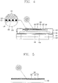
- FIG. 4 is a sectional view of the first body shown in FIG. 3 .
- FIG. 3 illustrates a separated state of the first body into the front case and the rear case.
- a transparent window 213 may be disposed at the rear case 212 so as to externally view (identify) light emitted from the luminous element assembly 230.
- 'transparent' may include 'completely transparent' or 'semitransparent'.
- the transparent window 213 may preferably be formed of a semitransparent material such that the luminous elements 231 cannot be viewed from the exterior when the luminous elements 231 do not emit light.
- the entire rear case 212 may be formed of a transparent material, instead of disposing the transparent window 213 at the rear case 212.
- a display module 151a may be mounted between the front case 211 and the rear case 212, and a window 215 for allowing output information on the display unit 151 to be externally visible may be mounted at one side of the display module 151a.
- a solar cell 240 for generating electrical energy by using ambient light of the mobile terminal may be mounted at another side of the display module 151 a.
- the solar cell 240 may convert optical energy into electrical energy to supply power to the battery 190 (i.e., the power supply unit).
- the solar cell 240 denotes a semiconductor device for converting optical energy into electrical energy by virtue of a photo voltaic effect.
- the present invention may employ various types of solar cells, such as silicon solar cell, thin film solar cell, dye-sensitized solar cell and the like, and preferably employ a solar cell with an extremely thin thickness so as to slim the thickness of the mobile terminal.
- the luminous element assembly 230 may include a plurality of luminous elements 231.
- the luminous elements 231 may be aligned in a matrix configuration with preset intervals in horizontal and vertical directions.
- the controller 180 (see FIG. 1 ) may control the luminous elements 231 to combine lights emitted therefrom such that visual information can be represented.
- the visual information may be represented by selectively operating part of the luminous elements 231 aligned in the matrix configuration.
- the luminous elements 231 may be implemented by use of light emitting diodes (LEDs) for reducing power loss and fabricating cost. Also, the luminous elements 231 may be implemented by using elements capable of representing monochromic color or plural colors.
- a representative luminous element 231 for representing a plurality of colors may include an RGB light emitting diode, which is configured to combine segments, which are capable of representing red, green and blue colors, and implement other colors by on/off combination of each segment.
- the luminous elements 231 may be disposed on one surface of the solar cell 240, namely, on a light (optical) absorption surface of the solar cell 240.
- the luminous elements 231 may be arranged with having spaces left for light absorption of the solar cell 240. Therefore, the solar cell 240 may absorb light through the spaces non-arranged by the luminous elements 231, thereby generating electrical energy.
- the present invention disposes the luminous elements 231 to overlap with the solar cell 240, such that a single space can be simultaneously used as 'space for generating electrical energy' and 'space for displaying visual information.
- the installation space of the solar cell 240 can be utilized as a display space for visual information, thereby reducing a dead space defined due to the installation of the solar cell 240.
- the luminous element assembly 230 may further include a transparent sheet 232 for supporting the luminous elements 231.
- the transparent sheet 232 may have transparent conductive patterns electrically connected to the luminous elements 231.
- the conductive patterns may function to electrically connect each of the luminous elements 231 to the controller 180 and to transfer a luminous signal generated from the controller 180 to the luminous elements 231.
- the conductive patterns may be formed of a transparent conductive material, for example, indium tin oxide (ITO) and the like.
- the conductive patterns may be formed on a front surface of the transparent sheet 232.
- the luminous elements 231 may be attached in a preset arrangement on the front surface of the transparent sheet 232 having the conductive patterns.
- a transparent protection film 233 for protecting the luminous elements 231 may further be attached on the front surface of the transparent sheet 232.
- an intermediate sheet 234 may further be located between the protection film 233 and the transparent sheet 232 so as to allow smooth surface-contact therebetween.
- the intermediate sheet 234 may define the spaces excluding the spaces having the luminous elements 231, and have the same thickness as the height of the luminous elements 231.
- the luminous elements 231, the transparent sheet 232 and the protection film 233 may be coupled together so as to implement the luminous element assembly 230.
- the luminous element assembly 230 may be attached onto a front surface of the solar cell 240 by use of an adhesive or adhesive sheet.
- the components configuring the luminous element assembly 230, excluding the luminous elements 231 may be made of a transparent material such that ambient light of the mobile terminal can be transmitted therethrough so as to reach the solar cell 240.
- the user may lay the mobile terminal so that the surface having the solar cell 240 faces upward, thereby charging the battery 190.
- FIG. 5 is a sectional view of a luminous element assembly in accordance with a second embodiment of the present invention.
- This embodiment employs like/similar reference numerals for like/similar components irrespective of different embodiments, so they all will be understood by the first description.
- a luminous element assembly 330 may be configured in the form of luminous elements 331 being attached on a front surface of a solar cell 340.
- the luminous elements 331 may be attached onto the solar cell 340 by use of an adhesive or adhesive film.
- transparent conductive patterns electrically connected to the luminous elements 331 may be formed on the front surface of the solar cell 340.
- the conductive patterns may function, as similar to the previous embodiment, to connect the plurality of luminous elements 331 to the controller 180, respectively, so as to render a luminous signal generated from the controller 180 applied to the luminous elements 331.
- a protection film 333 and an intermediate sheet 334 may further be provided.
- the luminous elements 331 are attached directly onto the front surface of the solar cell 340 and the conductive patterns are formed directly on the front surface of the solar cell 340.
- this structure does not need the transparent sheet 232 provided in the previous embodiment. Therefore, the luminous element assembly 330 may become slimmer in thickness as compared to that of the previous embodiment.
- FIGS. 6A and 6B are views illustrating operating states of a mobile terminal respectively employing the luminous element assembly 230, 330 having described above.
- Visual information represented by the luminous element assembly 220, 330 may include at least one of character, number, symbol and image. Such visual information may inform an originator's name, an originator's phone number and the like upon reception of call or text message.
- the visual information may be represented in the form of text, image and the like relating to indication information which notifies users of generation of a specific event (e.g., preset alarm, preset time, etc.).
- FIG. 6A illustrates that a user is informed of reception of a text message through an image represented by the luminous element assembly 220, 230, and additionally informed of an originator's name.
- FIG. 6B illustrates displaying of an originator's phone number by the luminous element assembly 220, 330 upon a call reception.
- FIG. 7 is a sectional view of a luminous element assembly in accordance with a third embodiment of the present invention.
- This embodiment employs like/similar reference numerals for like/similar components irrespective of different embodiments, so they all will be understood by the first description.
- a luminous element assembly 430 according to the third embodiment may further include a touch sheet 435, which is touch-sensitive, in addition to the aforementioned configuration.
- FIG. 7 illustrates the touch sheet 435 is further provided in addition to the configuration of the first embodiment having described above.
- the luminous element assembly 430 may include luminous elements 431, a transparent sheet 432 and the like.
- the touch sheet 435 may be located on one surface of the transparent sheet 432. This embodiment exemplarily illustrates that the touch sheet 435 is attached onto the front surface of the transparent sheet 432; however, the same may alternatively be attached onto a rear surface of the transparent sheet 432.
- the touch sheet 435 may be configured to detect a touch input on visual information represented by the luminous elements 431.
- the touch sheet 435 is shown having conductive patterns for generating an electric signal upon being touched.
- FIG. 7 exemplarily illustrates that the touch sheet 435 is further provided to the configuration according to the first embodiment; however, it may alternatively be possible that the touch sheet 435 is further provided to the configuration of the second embodiment.
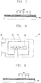
- FIG. 8 is a view illustrating an operating state of a mobile terminal having the luminous element assembly of FIG. 7 .
- Visual information represented by the luminous element assembly 430 may include information for a touch input.
- the visual information may be configured in the form of a keypad, which may be referred to as 'soft keys.'
- FIG. 8 exemplarily illustrates that the luminous element assembly 430 represents soft keys 438, namely, illustrates the soft keys 438 for controlling reproduction of music, for example, reproducing, stopping or pausing of music while listing to the music. A user may also enter desired information by touching the soft keys 438.
- the luminous element assembly 430 can also display phone calling or texting commands, and the controller 180 then executes a corresponding phone calling or texting operation when a corresponding phone calling or texting command is selected.
- the luminous element assembly 430 can also display shortcut icon information, icon information for frequently used operations, and icon information for different applications downloaded onto the terminal, calendar information, Internet operations, etc.
- the controller 180 then executes a corresponding operation when a displayed corresponding icon information is selected.
- the luminous element assembly 430 may perform a similar function to a 'touch screen' in combination with the touch sheet 435, and herein the features relating to touch input described in FIG. 1 may all be applicable to this structure.
- FIG. 9 is a sectional view of a luminous element assembly in accordance with a fourth embodiment of the present invention.
- This embodiment employs like/similar reference numerals for like/similar components irrespective of different embodiments, so they all will be understood by the first description.
- a luminous element assembly 530 according to the present invention may be configured to be touch-sensitive, similar to the luminous element assembly 430 of the third embodiment.
- the luminous element assembly 530 according to this fourth embodiment does not include the touch sheet 435 of the previous embodiment.
- the luminous element assembly 530 may include luminous elements 531, a transparent sheet 532, a protection film 533 and the like, similar to the configuration of the first embodiment.
- conductive patterns formed on the transparent sheet 532 may be used to detect touch inputs.
- the conductive patterns may be configured to generate a touch signal (electric signal) upon a touch being input on visual information.
- the conductive patterns of the transparent sheet 532 may perform not only a function of detecting touch inputs but also a function of applying a luminous signal to the luminous elements 531.
- FIG. 10 is a schematic view illustrating a structure of the conductive pattern provided at the transparent sheet of FIG. 9 .
- each conductive pattern for detecting touch inputs and transferring luminous signals may include first and second transparent patterns 551 and 552, and transparent lines 553 and 554.
- the first pattern 551 may have one end connected to one side of the luminous element 531 and occupy a partial area of a touch region.
- the second pattern 552 may have one end connected to another side of the luminous element 531 and occupy the residual area of the touch region. That is, the area defined by the first and second patterns 551 and 552 may configure a touch region for allowing touch inputs.
- One of the first and second patterns 551 and 552 may be connected to an anode of the luminous element 531 and another one connected to a cathode of the luminous element 531.
- the transparent lines 553 and 554 may be connected to another ends of the first and second patterns 551 and 552, respectively, and electrically connected to the controller 180 for control of the luminous elements 531.
- the transparent lines 553 and 554 may be electrically connected to a flexible printed circuit board attached onto the transparent sheet 532.
- the first and second patterns 551 and 552 may generate an electric signal upon a touch input being detected on a touch region. Such electric signal, namely, a touch signal, is forwarded to the controller 180 via the transparent lines 553 and 554. In addition, the luminous signals generated from the controller 180 may be forwarded to the luminous elements 531 via the transparent lines 553 and 554 and the first and second patterns 551 and 552.
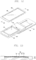
- FIG. 11 is a front perspective view of a mobile terminal in accordance with another embodiment of the present invention
- FIG. 12 is a rear perspective view of the mobile terminal shown in FIG. 11 .
- FIG. 11 exemplarily illustrates a slide type terminal having first body 610 and a second body 620.
- the first and second bodies 610 and 620 may be coupled to be relatively slidable from each other.
- the first body 610 is illustrated having the display unit 151, the speaker 152, the camera 121, the first manipulation unit 131 and the like
- the second body 620 is illustrated having the second manipulation unit 132, the third manipulation unit 133, the microphone 122, the interface unit 170 and the like.
- a luminous element assembly 630 and a solar cell 640 (see FIG. 13 ) applied to this embodiment may be disposed at a rear surface of the second body 620.
- the luminous element assembly and the solar cell may be disposed at one side of the display unit 151 or on an opposite surface (another surface).
- This structure may be equally applicable to other types of terminals, such as a swing type, a swivel type and the like.
- a battery cover 660 for covering the battery 190 may be detachably mounted to a rear surface of the second body 620.
- the luminous element assembly 630 and the solar cell 640 may be mounted to the battery cover 660.
- the rear surface of the second body 620 is illustrated having connection terminals 661 for an electrical connection with the battery cover 660.
- FIG. 13 is a sectional view of the battery cover of FIG. 12 .
- the battery cover 660 may be formed of a metal or synthetic resin, and include therein a solar cell 640 having luminous elements 631.
- the luminous element assembly 630 may include luminous elements 631, a transparent sheet 632, a protection film 633 and the like. Other components described above may all be applicable to this embodiment.
- the protection film 633 may preferably be formed semitransparent such that the luminous elements 631 cannot be visible from the exterior when not emitting light.
- the luminous element assembly 630 may be integrally formed with the battery cover 660 by an insert molding. Accordingly, the battery cover 660 can be slimmer in thickness and the components can be coupled together more strongly.
- the present invention utilizes an installation space of a solar cell as a display space of visual information by use of the luminous element assembly, thereby providing a mobile terminal having improved space usability.
- the present invention also disposes the luminous elements to be overlaid with the solar cell and thusly utilizes an installation space of the solar cell as a display space of visual information, thereby improving the space usability.
- the present invention allows information represented by the luminous elements to be touch-sensitive, thereby providing a structure capable of inputting information as well as outputting visual information.
- the present invention may implement two functions of touch detection and luminous signal transfer by use of single-layered transparent conductive patterns, thereby slimming a transparent touch input unit in thickness.
Landscapes
- Engineering & Computer Science (AREA)
- Signal Processing (AREA)
- Human Computer Interaction (AREA)
- General Engineering & Computer Science (AREA)
- Theoretical Computer Science (AREA)
- Computer Networks & Wireless Communication (AREA)
- Physics & Mathematics (AREA)
- General Physics & Mathematics (AREA)
- Telephone Set Structure (AREA)
- Telephone Function (AREA)
- Illuminated Signs And Luminous Advertising (AREA)
Claims (14)
- Mobiles Endgerät, das aufweist:eine drahtlose Kommunikationseinheit, die aufgebaut ist, um mit wenigstens einem anderen Endgerät drahtlos zu kommunizieren;einen Endgerätkörper mit einer Batterie (190);eine Solarzelle (240, 340, 640), die auf einer Oberfläche des Endgerätkörpers angeordnet ist und aufgebaut ist, um Lichtenergie in elektrische Energie umzuwandeln, um Leistung an die Batterie zuzuführen;mehrere Leuchtelemente (231, 331, 431, 531, 631), die auf einer Oberfläche der Solarelle angeordnet sind; undeine Steuerung (180), die aufgebaut ist, um die Leuchtelemente zu steuern, um visuelle Informationen anzuzeigen und basierend auf einer Benutzerauswahl von vorgegebenen Anzeigeleuchtelementen aus den mehreren Leuchtelementen einen vorgegebenen Betrieb auszuführen;wobei die Leuchtelemente (231, 331, 431, 531, 631) in einer Matrix mit vorher festgelegten Intervallen in den Horizontal- und Vertikalrichtungen und mit Resträumen für die Lichtabsorption der Solarzelle angeordnet sind.
- Endgerät nach Anspruch 1, das ferner aufweist:eine transparente Lage (232, 432, 532), die auf einer vorderen Oberfläche der Solarzelle angeordnet ist und aufgebaut ist, um die Leuchtelemente zu halten,wobei die transparente Lage (232, 432, 532) transparente leitende Muster umfasst, die mit den Leuchtelementen (231, 431, 531) elektrisch verbunden sind und aufgebaut sind, um Leuchtsignale an die Leuchtelemente (231, 431, 531) anzulegen.
- Endgerät nach Anspruch 2, das ferner aufweist:eine transparente dünne Schutzschicht (233, 433, 533), die auf einer vorderen Oberfläche der transparenten Lage (232, 432, 532) angebracht ist und aufgebaut ist, um die Leuchtelemente (231, 431, 531) zu schützen.
- Endgerät nach Anspruch 2 oder 3, das ferner aufweist:eine Berührungslage (435), die auf einer Oberfläche der transparenten Lage (232, 432) angeordnet ist und aufgebaut ist, um eine Berührungseingabe auf den visuellen Informationen zu erfassen, wobei die erfasste Berührungseingabe der Auswahl der vorgegebenen Anzeigeleuchtelemente von den mehreren Leuchtelementen entspricht.
- Endgerät nach einem der Ansprüche 2 bis 4, wobei jedes der leitenden Muster aufgebaut ist, um bei einer Berührungseingabe, die auf den visuellen Informationen erfasst wird, ein Berührungssignal zu erzeugen.
- Endgerät nach Anspruch 5, wobei jedes der leitenden Muster aufweist:ein erstes Muster (551), von dem ein Ende mit einer Seite eines entsprechenden Leuchtelements verbunden ist;ein zweites Muster (552), von dem ein Ende mit einer anderen Seite eines entsprechenden Leuchtelements verbunden ist, wobei das zweite Muster zusammen mit dem ersten Muster einen Berührungsbereich zum Erfassen der Berührungseingabe definiert; undtransparente Leitungen (553, 554), die jeweils an anderen Enden der ersten und zweiten Muster ausgebildet sind und mit der Steuerung verbunden sind, um die Leuchtelemente zu steuern.
- Endgerät nach einem der Ansprüche 1 bis 6, wobei die Leuchtelemente (331) auf einer vorderen Oberfläche der Solarzelle (340) angebracht sind, und
wobei transparente leitende Muster auf der vorderen Oberfläche der Solarzelle (340) ausgebildet sind, wobei die leitenden Muster mit den Leuchtelementen (331) elektrisch verbunden sind und aufgebaut sind, um Leuchtsignale an die Leuchtelemente (331) anzulegen. - Endgerät nach Anspruch 7, das ferner aufweist:eine Schutzschicht (333) mit einem transparenten Material, das auf der vorderen Oberfläche der Solarzelle angeordnet ist und aufgebaut ist, um die Leuchtelemente zu schützen.
- Endgerät nach einem der Ansprüche 1 bis 8, wobei die visuellen Informationen einen Namen eines ankommenden Anrufers und/oder eine Telefonnummer des an-kommenden Anrufers und/oder eine Anzeigeinformation, die eine Erzeugung eines spezifischen Ereignisses anzeigt, umfassen.
- Endgerät nach einem der Ansprüche 1 bis 9, das ferner aufweist:eine Anzeigeeinheit (151), die auf einer Oberfläche des Endgerätkörpers ange-ordnet ist und aufgebaut ist, um neben den durch die Leuchtelemente angezeigten visuellen Informationen andere Informationen anzuzeigen,wobei die Solarzelle und die Leuchtelemente auf der anderen Oberfläche des Endgerätkörpers angeordnet sind.
- Endgerät nach einem der Ansprüche 1 bis 10, das ferner aufweist:eine Batterieabdeckung (660), die lösbar an dem Endgerätkörper montiert ist und aufgebaut ist, um die Batterie abzuschirmen,wobei die Solarzelle (640) und die Leuchtelemente (631) auf der Batterieabdeckung (660) angebracht sind.
- Endgerät nach einem der Ansprüche 1 bis 11, wobei der Endgerätkörper einen ersten Körper (610) und einen zweiten Körper (620) umfasst, die derart gekoppelt sind, dass sie relativ drehbar sind und einen geschlossenen Aufbau und einen geöffneten Aufbau implementieren, und
wobei die Solarzelle (640) und die Leuchtelemente (631) auf wenigstens einem der ersten und zweiten Körper angeordnet sind,
wobei die Solarzelle und die Leuchtelemente in einem geschlossenen Aufbau auf einer nach außen freiliegenden Oberfläche des ersten oder zweiten Körpers angeordnet sind. - Endgerät nach einem der Ansprüche 1 bis 12, wobei die vorgegebenen Anzeigeleuchtelemente Audio-/Videobefehle anzeigen und die Steuerung ferner aufgebaut ist, um einen entsprechenden Audio-/Videobetrieb auszuführen, wenn ein entsprechender Audio-/Videobefehl ausgewählt wird.
- Verfahren zur Steuerung eines mobilen Endgeräts, wobei das Verfahren aufweist:Zulassen einer drahtlosen Kommunikation mit wenigstens einem anderen Endgerät über eine drahtlose Kommunikationseinheit;Anzeigen von visuellen Informationen über eine in dem mobilen Endgerät enthaltene Steuerung unter Verwendung mehrerer Leuchtelemente, die auf einer Oberfläche einer Solarzelle angeordnet sind, wobei die Solarzelle auf einer Oberfläche des Endgerätkörpers, der eine Batterie umfasst, angeordnet ist und aufgebaut ist, um Lichtenergie in elektrische Energie umzuwandeln, um Leistung an die Batterie zuzuführen; undAusführen eines vorgegebenen Betriebs basierend auf einer Benutzerauswahl vorgegebener Anzeigeleuchtelemente von den mehreren Leuchtelementen;wobei die Leuchtelemente (231, 331, 431, 531, 631) in einer Matrix mit vorher festgelegten Intervallen in den Horizontal- und Vertikalrichtungen und mit Resträumen für die Lichtabsorption der Solarzelle angeordnet sind.
Applications Claiming Priority (1)
| Application Number | Priority Date | Filing Date | Title |
|---|---|---|---|
| KR1020090079296A KR101631907B1 (ko) | 2009-08-26 | 2009-08-26 | 이동 단말기 |
Publications (3)
| Publication Number | Publication Date |
|---|---|
| EP2290933A2 EP2290933A2 (de) | 2011-03-02 |
| EP2290933A3 EP2290933A3 (de) | 2015-06-17 |
| EP2290933B1 true EP2290933B1 (de) | 2017-04-26 |
Family
ID=43244802
Family Applications (1)
| Application Number | Title | Priority Date | Filing Date |
|---|---|---|---|
| EP10169999.9A Not-in-force EP2290933B1 (de) | 2009-08-26 | 2010-07-19 | Mobiles Endgerät mit Solarzelle und einer Vielzahl von Leuchtelementen |
Country Status (4)
| Country | Link |
|---|---|
| US (1) | US8626250B2 (de) |
| EP (1) | EP2290933B1 (de) |
| KR (1) | KR101631907B1 (de) |
| CN (1) | CN102006093B (de) |
Families Citing this family (11)
| Publication number | Priority date | Publication date | Assignee | Title |
|---|---|---|---|---|
| EP2564425B1 (de) * | 2010-04-28 | 2019-05-29 | Nokia Technologies Oy | Anordnung aus pv-zellen |
| KR101131977B1 (ko) * | 2011-04-26 | 2012-03-29 | (주)켐리치 | 배터리 커버에 발광장치가 구비된 휴대폰 |
| US9368987B2 (en) * | 2012-10-24 | 2016-06-14 | Blackberry Limited | Solar cell and portable electronic device |
| CN103137024B (zh) | 2013-02-04 | 2015-09-09 | 小米科技有限责任公司 | 一种显示装置及一种移动终端 |
| CN103258841A (zh) * | 2013-04-26 | 2013-08-21 | 京东方科技集团股份有限公司 | 显示面板、显示装置及电子器件 |
| US9375874B2 (en) * | 2013-12-03 | 2016-06-28 | Htc Corporation | Accessory, electronic assembly, control method, and method for forming an accessory |
| CN103676361B (zh) * | 2013-12-24 | 2016-01-13 | 京东方科技集团股份有限公司 | 显示屏及其制造方法和显示装置 |
| FR3043273B1 (fr) * | 2015-11-02 | 2018-09-07 | Moukangala Ngaka | Systeme d'alimentation et de recharge par energie solaire d'appareils mobiles utilisant internet |
| CN111328219A (zh) * | 2020-03-31 | 2020-06-23 | Oppo广东移动通信有限公司 | 用于电子设备的背壳、电子设备、制备方法 |
| CN111884313A (zh) * | 2020-06-22 | 2020-11-03 | 陈维潇 | 基于太阳能发电的5g移动通信aau设备及其控制方法 |
| US12102456B2 (en) * | 2021-10-26 | 2024-10-01 | United States Government As Represented By The Department Of Veterans Affairs | Equipment and methods for remote neuropsychological assessment |
Family Cites Families (10)
| Publication number | Priority date | Publication date | Assignee | Title |
|---|---|---|---|---|
| US7206044B2 (en) * | 2001-10-31 | 2007-04-17 | Motorola, Inc. | Display and solar cell device |
| JP2004312476A (ja) * | 2003-04-09 | 2004-11-04 | Nec Corp | 折り畳み式携帯情報端末 |
| JP2005136531A (ja) * | 2003-10-29 | 2005-05-26 | Hitachi Electronics Service Co Ltd | 透明太陽電池付携帯電話機 |
| US7339636B2 (en) * | 2003-12-02 | 2008-03-04 | Motorola, Inc. | Color display and solar cell device |
| US20070032268A1 (en) * | 2005-08-02 | 2007-02-08 | Gotfried Bradley L | Communications device and card |
| CN2924944Y (zh) | 2006-07-05 | 2007-07-18 | 北京恒基伟业投资发展有限公司 | 内置式太阳能手机 |
| KR20080014425A (ko) * | 2006-08-11 | 2008-02-14 | 엘지전자 주식회사 | 이동통신 단말기의 듀얼 표시 장치 |
| KR101303155B1 (ko) * | 2007-03-16 | 2013-09-09 | 엘지전자 주식회사 | 휴대 단말기 |
| US20080094025A1 (en) * | 2006-10-20 | 2008-04-24 | Rosenblatt Michael N | Solar cells on portable devices |
| CN101452970B (zh) | 2007-11-28 | 2011-06-22 | 鸿富锦精密工业(深圳)有限公司 | 太阳能电池模组及便携式电子装置 |
-
2009
- 2009-08-26 KR KR1020090079296A patent/KR101631907B1/ko not_active Expired - Fee Related
-
2010
- 2010-07-13 US US12/835,389 patent/US8626250B2/en not_active Expired - Fee Related
- 2010-07-19 EP EP10169999.9A patent/EP2290933B1/de not_active Not-in-force
- 2010-08-23 CN CN201010261209.5A patent/CN102006093B/zh not_active Expired - Fee Related
Non-Patent Citations (1)
| Title |
|---|
| None * |
Also Published As
| Publication number | Publication date |
|---|---|
| KR20110021476A (ko) | 2011-03-04 |
| CN102006093B (zh) | 2014-12-24 |
| EP2290933A2 (de) | 2011-03-02 |
| KR101631907B1 (ko) | 2016-06-20 |
| EP2290933A3 (de) | 2015-06-17 |
| CN102006093A (zh) | 2011-04-06 |
| US20110053652A1 (en) | 2011-03-03 |
| US8626250B2 (en) | 2014-01-07 |
Similar Documents
| Publication | Publication Date | Title |
|---|---|---|
| EP2290933B1 (de) | Mobiles Endgerät mit Solarzelle und einer Vielzahl von Leuchtelementen | |
| US8471810B2 (en) | Mobile terminal | |
| US9392706B2 (en) | Mobile terminal | |
| EP2472832B1 (de) | Fenster, entsprechendes Herstellungsverfahren und tragbares Endgerät mit diesem Fenster | |
| US8774879B2 (en) | Mobile terminal | |
| KR101556161B1 (ko) | 휴대용 단말기 | |
| KR101570416B1 (ko) | 이동 단말기 | |
| US9258393B2 (en) | Mobile terminal | |
| KR20100053349A (ko) | 터치 모듈, 그 터치 모듈의 제조 방법 및 그 터치 모듈을 갖는 휴대 단말기 | |
| KR20100000797A (ko) | 휴대 단말기 | |
| US9244534B2 (en) | Mobile terminal | |
| KR20110068666A (ko) | 사이드 터치 입력 수단을 구비한 이동단말기 및 그의 기능 수행 방법 | |
| KR20130104765A (ko) | 이동단말기 | |
| KR20130105082A (ko) | 이동단말기 | |
| KR20110002366A (ko) | 이동 단말기 | |
| KR101771453B1 (ko) | 이동 단말기 | |
| KR101631949B1 (ko) | 휴대 단말기 | |
| KR20140036873A (ko) | 배터리팩과 이를 구비하는 이동 단말기 | |
| KR20100039977A (ko) | 이동 단말기 및 그 무선 통신 채널 변경 방법 | |
| KR20110062090A (ko) | 이동단말기 및 그의 데이터 전송 방법 | |
| KR20120055160A (ko) | 이동 단말기 | |
| KR101688945B1 (ko) | 이동단말기 및 그의 입력수단 제어방법 | |
| KR20110035672A (ko) | 이동 단말기 | |
| KR101279517B1 (ko) | 이동 단말기 | |
| KR20130008923A (ko) | 이동 단말기 |
Legal Events
| Date | Code | Title | Description |
|---|---|---|---|
| PUAI | Public reference made under article 153(3) epc to a published international application that has entered the european phase |
Free format text: ORIGINAL CODE: 0009012 |
|
| AK | Designated contracting states |
Kind code of ref document: A2 Designated state(s): AL AT BE BG CH CY CZ DE DK EE ES FI FR GB GR HR HU IE IS IT LI LT LU LV MC MK MT NL NO PL PT RO SE SI SK SM TR |
|
| AX | Request for extension of the european patent |
Extension state: BA ME RS |
|
| RAP1 | Party data changed (applicant data changed or rights of an application transferred) |
Owner name: LG ELECTRONICS INC. |
|
| PUAL | Search report despatched |
Free format text: ORIGINAL CODE: 0009013 |
|
| AK | Designated contracting states |
Kind code of ref document: A3 Designated state(s): AL AT BE BG CH CY CZ DE DK EE ES FI FR GB GR HR HU IE IS IT LI LT LU LV MC MK MT NL NO PL PT RO SE SI SK SM TR |
|
| AX | Request for extension of the european patent |
Extension state: BA ME RS |
|
| RIC1 | Information provided on ipc code assigned before grant |
Ipc: G09G 3/32 20060101ALI20150513BHEP Ipc: H02J 7/35 20060101ALN20150513BHEP Ipc: H04W 52/02 20090101ALN20150513BHEP Ipc: H04M 1/02 20060101ALN20150513BHEP Ipc: H04M 1/57 20060101ALN20150513BHEP Ipc: H04M 1/22 20060101AFI20150513BHEP |
|
| 17P | Request for examination filed |
Effective date: 20150724 |
|
| RBV | Designated contracting states (corrected) |
Designated state(s): AL AT BE BG CH CY CZ DE DK EE ES FI FR GB GR HR HU IE IS IT LI LT LU LV MC MK MT NL NO PL PT RO SE SI SK SM TR |
|
| REG | Reference to a national code |
Ref country code: DE Ref legal event code: R079 Ref document number: 602010041805 Country of ref document: DE Free format text: PREVIOUS MAIN CLASS: H04M0001730000 Ipc: H04M0001220000 |
|
| GRAP | Despatch of communication of intention to grant a patent |
Free format text: ORIGINAL CODE: EPIDOSNIGR1 |
|
| STAA | Information on the status of an ep patent application or granted ep patent |
Free format text: STATUS: GRANT OF PATENT IS INTENDED |
|
| RIC1 | Information provided on ipc code assigned before grant |
Ipc: H04W 52/02 20090101ALN20161129BHEP Ipc: H04M 1/57 20060101ALN20161129BHEP Ipc: H04M 1/02 20060101ALN20161129BHEP Ipc: H04M 1/22 20060101AFI20161129BHEP Ipc: G09G 3/32 20060101ALI20161129BHEP Ipc: H02J 7/35 20060101ALN20161129BHEP |
|
| INTG | Intention to grant announced |
Effective date: 20161214 |
|
| GRAS | Grant fee paid |
Free format text: ORIGINAL CODE: EPIDOSNIGR3 |
|
| GRAA | (expected) grant |
Free format text: ORIGINAL CODE: 0009210 |
|
| STAA | Information on the status of an ep patent application or granted ep patent |
Free format text: STATUS: THE PATENT HAS BEEN GRANTED |
|
| AK | Designated contracting states |
Kind code of ref document: B1 Designated state(s): AL AT BE BG CH CY CZ DE DK EE ES FI FR GB GR HR HU IE IS IT LI LT LU LV MC MK MT NL NO PL PT RO SE SI SK SM TR |
|
| REG | Reference to a national code |
Ref country code: GB Ref legal event code: FG4D |
|
| REG | Reference to a national code |
Ref country code: CH Ref legal event code: EP |
|
| REG | Reference to a national code |
Ref country code: AT Ref legal event code: REF Ref document number: 888781 Country of ref document: AT Kind code of ref document: T Effective date: 20170515 |
|
| REG | Reference to a national code |
Ref country code: IE Ref legal event code: FG4D |
|
| REG | Reference to a national code |
Ref country code: DE Ref legal event code: R096 Ref document number: 602010041805 Country of ref document: DE |
|
| REG | Reference to a national code |
Ref country code: FR Ref legal event code: PLFP Year of fee payment: 8 |
|
| REG | Reference to a national code |
Ref country code: NL Ref legal event code: MP Effective date: 20170426 |
|
| REG | Reference to a national code |
Ref country code: LT Ref legal event code: MG4D |
|
| REG | Reference to a national code |
Ref country code: AT Ref legal event code: MK05 Ref document number: 888781 Country of ref document: AT Kind code of ref document: T Effective date: 20170426 |
|
| PG25 | Lapsed in a contracting state [announced via postgrant information from national office to epo] |
Ref country code: NL Free format text: LAPSE BECAUSE OF FAILURE TO SUBMIT A TRANSLATION OF THE DESCRIPTION OR TO PAY THE FEE WITHIN THE PRESCRIBED TIME-LIMIT Effective date: 20170426 |
|
| PG25 | Lapsed in a contracting state [announced via postgrant information from national office to epo] |
Ref country code: ES Free format text: LAPSE BECAUSE OF FAILURE TO SUBMIT A TRANSLATION OF THE DESCRIPTION OR TO PAY THE FEE WITHIN THE PRESCRIBED TIME-LIMIT Effective date: 20170426 Ref country code: FI Free format text: LAPSE BECAUSE OF FAILURE TO SUBMIT A TRANSLATION OF THE DESCRIPTION OR TO PAY THE FEE WITHIN THE PRESCRIBED TIME-LIMIT Effective date: 20170426 Ref country code: HR Free format text: LAPSE BECAUSE OF FAILURE TO SUBMIT A TRANSLATION OF THE DESCRIPTION OR TO PAY THE FEE WITHIN THE PRESCRIBED TIME-LIMIT Effective date: 20170426 Ref country code: NO Free format text: LAPSE BECAUSE OF FAILURE TO SUBMIT A TRANSLATION OF THE DESCRIPTION OR TO PAY THE FEE WITHIN THE PRESCRIBED TIME-LIMIT Effective date: 20170726 Ref country code: LT Free format text: LAPSE BECAUSE OF FAILURE TO SUBMIT A TRANSLATION OF THE DESCRIPTION OR TO PAY THE FEE WITHIN THE PRESCRIBED TIME-LIMIT Effective date: 20170426 Ref country code: AT Free format text: LAPSE BECAUSE OF FAILURE TO SUBMIT A TRANSLATION OF THE DESCRIPTION OR TO PAY THE FEE WITHIN THE PRESCRIBED TIME-LIMIT Effective date: 20170426 Ref country code: GR Free format text: LAPSE BECAUSE OF FAILURE TO SUBMIT A TRANSLATION OF THE DESCRIPTION OR TO PAY THE FEE WITHIN THE PRESCRIBED TIME-LIMIT Effective date: 20170727 |
|
| PGFP | Annual fee paid to national office [announced via postgrant information from national office to epo] |
Ref country code: GB Payment date: 20170721 Year of fee payment: 8 Ref country code: FR Payment date: 20170724 Year of fee payment: 8 Ref country code: DE Payment date: 20170713 Year of fee payment: 8 |
|
| PG25 | Lapsed in a contracting state [announced via postgrant information from national office to epo] |
Ref country code: SE Free format text: LAPSE BECAUSE OF FAILURE TO SUBMIT A TRANSLATION OF THE DESCRIPTION OR TO PAY THE FEE WITHIN THE PRESCRIBED TIME-LIMIT Effective date: 20170426 Ref country code: BG Free format text: LAPSE BECAUSE OF FAILURE TO SUBMIT A TRANSLATION OF THE DESCRIPTION OR TO PAY THE FEE WITHIN THE PRESCRIBED TIME-LIMIT Effective date: 20170726 Ref country code: PL Free format text: LAPSE BECAUSE OF FAILURE TO SUBMIT A TRANSLATION OF THE DESCRIPTION OR TO PAY THE FEE WITHIN THE PRESCRIBED TIME-LIMIT Effective date: 20170426 Ref country code: LV Free format text: LAPSE BECAUSE OF FAILURE TO SUBMIT A TRANSLATION OF THE DESCRIPTION OR TO PAY THE FEE WITHIN THE PRESCRIBED TIME-LIMIT Effective date: 20170426 Ref country code: IS Free format text: LAPSE BECAUSE OF FAILURE TO SUBMIT A TRANSLATION OF THE DESCRIPTION OR TO PAY THE FEE WITHIN THE PRESCRIBED TIME-LIMIT Effective date: 20170826 |
|
| REG | Reference to a national code |
Ref country code: DE Ref legal event code: R097 Ref document number: 602010041805 Country of ref document: DE |
|
| PG25 | Lapsed in a contracting state [announced via postgrant information from national office to epo] |
Ref country code: SK Free format text: LAPSE BECAUSE OF FAILURE TO SUBMIT A TRANSLATION OF THE DESCRIPTION OR TO PAY THE FEE WITHIN THE PRESCRIBED TIME-LIMIT Effective date: 20170426 Ref country code: CZ Free format text: LAPSE BECAUSE OF FAILURE TO SUBMIT A TRANSLATION OF THE DESCRIPTION OR TO PAY THE FEE WITHIN THE PRESCRIBED TIME-LIMIT Effective date: 20170426 Ref country code: DK Free format text: LAPSE BECAUSE OF FAILURE TO SUBMIT A TRANSLATION OF THE DESCRIPTION OR TO PAY THE FEE WITHIN THE PRESCRIBED TIME-LIMIT Effective date: 20170426 Ref country code: EE Free format text: LAPSE BECAUSE OF FAILURE TO SUBMIT A TRANSLATION OF THE DESCRIPTION OR TO PAY THE FEE WITHIN THE PRESCRIBED TIME-LIMIT Effective date: 20170426 Ref country code: RO Free format text: LAPSE BECAUSE OF FAILURE TO SUBMIT A TRANSLATION OF THE DESCRIPTION OR TO PAY THE FEE WITHIN THE PRESCRIBED TIME-LIMIT Effective date: 20170426 |
|
| PG25 | Lapsed in a contracting state [announced via postgrant information from national office to epo] |
Ref country code: SM Free format text: LAPSE BECAUSE OF FAILURE TO SUBMIT A TRANSLATION OF THE DESCRIPTION OR TO PAY THE FEE WITHIN THE PRESCRIBED TIME-LIMIT Effective date: 20170426 Ref country code: IT Free format text: LAPSE BECAUSE OF FAILURE TO SUBMIT A TRANSLATION OF THE DESCRIPTION OR TO PAY THE FEE WITHIN THE PRESCRIBED TIME-LIMIT Effective date: 20170426 |
|
| REG | Reference to a national code |
Ref country code: CH Ref legal event code: PL |
|
| PLBE | No opposition filed within time limit |
Free format text: ORIGINAL CODE: 0009261 |
|
| STAA | Information on the status of an ep patent application or granted ep patent |
Free format text: STATUS: NO OPPOSITION FILED WITHIN TIME LIMIT |
|
| 26N | No opposition filed |
Effective date: 20180129 |
|
| REG | Reference to a national code |
Ref country code: IE Ref legal event code: MM4A |
|
| PG25 | Lapsed in a contracting state [announced via postgrant information from national office to epo] |
Ref country code: CH Free format text: LAPSE BECAUSE OF NON-PAYMENT OF DUE FEES Effective date: 20170731 Ref country code: IE Free format text: LAPSE BECAUSE OF NON-PAYMENT OF DUE FEES Effective date: 20170719 Ref country code: LI Free format text: LAPSE BECAUSE OF NON-PAYMENT OF DUE FEES Effective date: 20170731 |
|
| PG25 | Lapsed in a contracting state [announced via postgrant information from national office to epo] |
Ref country code: SI Free format text: LAPSE BECAUSE OF FAILURE TO SUBMIT A TRANSLATION OF THE DESCRIPTION OR TO PAY THE FEE WITHIN THE PRESCRIBED TIME-LIMIT Effective date: 20170426 |
|
| REG | Reference to a national code |
Ref country code: BE Ref legal event code: MM Effective date: 20170731 |
|
| PG25 | Lapsed in a contracting state [announced via postgrant information from national office to epo] |
Ref country code: LU Free format text: LAPSE BECAUSE OF NON-PAYMENT OF DUE FEES Effective date: 20170719 |
|
| PG25 | Lapsed in a contracting state [announced via postgrant information from national office to epo] |
Ref country code: BE Free format text: LAPSE BECAUSE OF NON-PAYMENT OF DUE FEES Effective date: 20170731 |
|
| PG25 | Lapsed in a contracting state [announced via postgrant information from national office to epo] |
Ref country code: MT Free format text: LAPSE BECAUSE OF NON-PAYMENT OF DUE FEES Effective date: 20170719 |
|
| REG | Reference to a national code |
Ref country code: DE Ref legal event code: R119 Ref document number: 602010041805 Country of ref document: DE |
|
| GBPC | Gb: european patent ceased through non-payment of renewal fee |
Effective date: 20180719 |
|
| PG25 | Lapsed in a contracting state [announced via postgrant information from national office to epo] |
Ref country code: DE Free format text: LAPSE BECAUSE OF NON-PAYMENT OF DUE FEES Effective date: 20190201 Ref country code: GB Free format text: LAPSE BECAUSE OF NON-PAYMENT OF DUE FEES Effective date: 20180719 Ref country code: FR Free format text: LAPSE BECAUSE OF NON-PAYMENT OF DUE FEES Effective date: 20180731 |
|
| PG25 | Lapsed in a contracting state [announced via postgrant information from national office to epo] |
Ref country code: MC Free format text: LAPSE BECAUSE OF FAILURE TO SUBMIT A TRANSLATION OF THE DESCRIPTION OR TO PAY THE FEE WITHIN THE PRESCRIBED TIME-LIMIT Effective date: 20170426 Ref country code: HU Free format text: LAPSE BECAUSE OF FAILURE TO SUBMIT A TRANSLATION OF THE DESCRIPTION OR TO PAY THE FEE WITHIN THE PRESCRIBED TIME-LIMIT; INVALID AB INITIO Effective date: 20100719 |
|
| PG25 | Lapsed in a contracting state [announced via postgrant information from national office to epo] |
Ref country code: CY Free format text: LAPSE BECAUSE OF NON-PAYMENT OF DUE FEES Effective date: 20170426 |
|
| PG25 | Lapsed in a contracting state [announced via postgrant information from national office to epo] |
Ref country code: MK Free format text: LAPSE BECAUSE OF FAILURE TO SUBMIT A TRANSLATION OF THE DESCRIPTION OR TO PAY THE FEE WITHIN THE PRESCRIBED TIME-LIMIT Effective date: 20170426 |
|
| PG25 | Lapsed in a contracting state [announced via postgrant information from national office to epo] |
Ref country code: TR Free format text: LAPSE BECAUSE OF FAILURE TO SUBMIT A TRANSLATION OF THE DESCRIPTION OR TO PAY THE FEE WITHIN THE PRESCRIBED TIME-LIMIT Effective date: 20170426 |
|
| PG25 | Lapsed in a contracting state [announced via postgrant information from national office to epo] |
Ref country code: PT Free format text: LAPSE BECAUSE OF FAILURE TO SUBMIT A TRANSLATION OF THE DESCRIPTION OR TO PAY THE FEE WITHIN THE PRESCRIBED TIME-LIMIT Effective date: 20170426 |
|
| PG25 | Lapsed in a contracting state [announced via postgrant information from national office to epo] |
Ref country code: AL Free format text: LAPSE BECAUSE OF FAILURE TO SUBMIT A TRANSLATION OF THE DESCRIPTION OR TO PAY THE FEE WITHIN THE PRESCRIBED TIME-LIMIT Effective date: 20170426 |