EP2290936A1 - Procédé et appareil pour quantifier un signal sonore reçu dans un réseau de télécommunication - Google Patents
Procédé et appareil pour quantifier un signal sonore reçu dans un réseau de télécommunication Download PDFInfo
- Publication number
- EP2290936A1 EP2290936A1 EP10008914A EP10008914A EP2290936A1 EP 2290936 A1 EP2290936 A1 EP 2290936A1 EP 10008914 A EP10008914 A EP 10008914A EP 10008914 A EP10008914 A EP 10008914A EP 2290936 A1 EP2290936 A1 EP 2290936A1
- Authority
- EP
- European Patent Office
- Prior art keywords
- tone signal
- received
- bandstop
- type
- bandpass
- Prior art date
- Legal status (The legal status is an assumption and is not a legal conclusion. Google has not performed a legal analysis and makes no representation as to the accuracy of the status listed.)
- Withdrawn
Links
- 238000000034 method Methods 0.000 title claims abstract description 40
- 238000004458 analytical method Methods 0.000 claims abstract description 26
- 238000001914 filtration Methods 0.000 claims description 37
- 230000003595 spectral effect Effects 0.000 claims description 24
- 238000012545 processing Methods 0.000 claims description 13
- 238000011002 quantification Methods 0.000 claims description 11
- 230000011664 signaling Effects 0.000 claims description 7
- 230000003111 delayed effect Effects 0.000 claims description 5
- 230000005540 biological transmission Effects 0.000 description 4
- 238000004891 communication Methods 0.000 description 4
- 230000033764 rhythmic process Effects 0.000 description 4
- 239000000872 buffer Substances 0.000 description 3
- 238000004883 computer application Methods 0.000 description 2
- 238000010586 diagram Methods 0.000 description 2
- 238000010295 mobile communication Methods 0.000 description 2
- JNUZADQZHYFJGW-JOCHJYFZSA-N (2R)-N-[3-[5-fluoro-2-(2-fluoro-3-methylsulfonylanilino)pyrimidin-4-yl]-1H-indol-7-yl]-3-methoxy-2-(4-methylpiperazin-1-yl)propanamide Chemical compound FC=1C(=NC(=NC=1)NC1=C(C(=CC=C1)S(=O)(=O)C)F)C1=CNC2=C(C=CC=C12)NC([C@@H](COC)N1CCN(CC1)C)=O JNUZADQZHYFJGW-JOCHJYFZSA-N 0.000 description 1
- 241000466079 Exyra fax Species 0.000 description 1
- 238000012512 characterization method Methods 0.000 description 1
- 230000001419 dependent effect Effects 0.000 description 1
- 238000001514 detection method Methods 0.000 description 1
- 230000006870 function Effects 0.000 description 1
- 230000010354 integration Effects 0.000 description 1
- 230000035945 sensitivity Effects 0.000 description 1
- 230000005236 sound signal Effects 0.000 description 1
- 238000012546 transfer Methods 0.000 description 1
- 230000000007 visual effect Effects 0.000 description 1
- 238000005303 weighing Methods 0.000 description 1
Images


Classifications
-
- H—ELECTRICITY
- H04—ELECTRIC COMMUNICATION TECHNIQUE
- H04M—TELEPHONIC COMMUNICATION
- H04M3/00—Automatic or semi-automatic exchanges
- H04M3/02—Calling substations, e.g. by ringing
-
- H—ELECTRICITY
- H04—ELECTRIC COMMUNICATION TECHNIQUE
- H04M—TELEPHONIC COMMUNICATION
- H04M3/00—Automatic or semi-automatic exchanges
- H04M3/22—Arrangements for supervision, monitoring or testing
-
- H—ELECTRICITY
- H04—ELECTRIC COMMUNICATION TECHNIQUE
- H04M—TELEPHONIC COMMUNICATION
- H04M3/00—Automatic or semi-automatic exchanges
- H04M3/22—Arrangements for supervision, monitoring or testing
- H04M3/26—Arrangements for supervision, monitoring or testing with means for applying test signals or for measuring
- H04M3/28—Automatic routine testing ; Fault testing; Installation testing; Test methods, test equipment or test arrangements therefor
- H04M3/30—Automatic routine testing ; Fault testing; Installation testing; Test methods, test equipment or test arrangements therefor for subscriber's lines, for the local loop
- H04M3/307—Automatic routine testing ; Fault testing; Installation testing; Test methods, test equipment or test arrangements therefor for subscriber's lines, for the local loop using ringback
-
- H—ELECTRICITY
- H04—ELECTRIC COMMUNICATION TECHNIQUE
- H04M—TELEPHONIC COMMUNICATION
- H04M2201/00—Electronic components, circuits, software, systems or apparatus used in telephone systems
- H04M2201/12—Counting circuits
-
- H—ELECTRICITY
- H04—ELECTRIC COMMUNICATION TECHNIQUE
- H04M—TELEPHONIC COMMUNICATION
- H04M2201/00—Electronic components, circuits, software, systems or apparatus used in telephone systems
- H04M2201/14—Delay circuits; Timers
Definitions
- telecommunications networks for signalling purposes, different tone signals are exchanged between user equipment and network devices, such as telephones, switches, repeaters and radio access units or radio base stations in radio telecommunications networks.
- network devices such as telephones, switches, repeaters and radio access units or radio base stations in radio telecommunications networks.
- ringback tone signal An example of such a signalling tone signal is called "ringback tone signal". This is the audible ringing that is heard by a calling party at user equipment in a telecommunications network after dialling and prior to the call being answered by the called party. This ringback tone assures the calling party that a ringing signal is being transferred to the called party.
- the ringback tone signal is not generated by the user equipment of the calling party.
- the ringback tone signal may be generated by a local switch of the telecommunications network serving the calling party or by a remote switch of the telecommunications network serving the called party, for example.
- the type of ringback tone i.e. the sound, duration and rhythm of the ringback tone signal, may differ in various countries.
- the ringback tone signal may be out of synchronization with the actual ringing signal heard by the called party.
- the ringback tone signal generally starts and stops when the actual ringing signal provided to the called party starts and stops.
- Private Branch eXchanges may forward a tone signal to a calling party if the switchboard operator has put the call on hold to transfer the incoming call to a desired called party.
- PBX Private Branch eXchanges
- tone signals may be produced by data modems or the like connected to a telephone line, for example.
- the received tone signal is produced at a remote switch of a called party, for example, by evaluating the quality of the received tone signal one may get an indication about the quality of the telecommunications link between the calling party and the remote switch or another network device that produces the tone signal.
- a measure to improve the radio link quality can be to increase the RF transmit power at the side of the telecommunications network or to increase the receiver sensitivity at the end user device, for example.
- the quality data derived from the received tone signals is gathered and analysed in association with route information of the telecommunications line over which the tone signal is received. From this analysis, for setting up a call to a particular destination, routes or telecommunications lines providing an unacceptable quality can be excluded. The other way around, one may of course use the gathered quality information to select particular routes or telecommunications lines providing a desired quality.
- telecommunications line includes both wired and wireless connections.
- the present invention provides a method of quantifying a tone signal received in a telecommunications network, which method comprises the steps of:
- the received tone signal is subjected to bandpass filtering and bandstop filtering, wherein the type of filtering applied is selected on the basis of an identified type of the received tone signal.
- the bandpass filtered tone signal reflects the amount in which the received tone signal matches the ideal tone signal according to the identified type.
- the bandstop filtered tone signal contains all signal components which, in fact, should not be present when compared to the ideal tone signal according to the type of tone signal identified.
- the received tone signal can be quantified for providing a quality indication thereof, for example.
- the received tone signal in order to apply the correct filtering in accordance with the type of tone signal identified, is delayed to introduce additional time required to identify the type of the received tone signal.
- the received tone signal may comprise a sequence of tone signal bursts.
- the delaying of the tone signal, the bandpass filtering and bandstop filtering as well as the analysing and quantifying steps are applied to each tone signal burst of the sequence of tone signal bursts.
- ringback tone signals for example, network operators sometimes generate a few bursts of a ringback tone signal from the local network equipment to which the user equipment of the calling party connects, before transferring the actual ringback tone signal bursts received from the remote network devices to which the called party connects.
- type of ringback tone may differ in this case.
- the received tone signal is quantified by the worst or lowest quality indication of a tone signal burst of the received plurality of tone signal bursts.
- the received tone signal is subjected to spectral power computation in a plurality of predetermined frequency bands including DC, providing a spectral power distribution over the frequency bands, and wherein the type of received tone signal is identified among stored types of tone signals using the computed spectral power distribution.
- the type of the received tone signal is than identified using peaks in the spectral power distribution, for example. That is, for the purpose of identification of the tone signal, spectral power peaks having a value above a threshold are selected and the position of these peaks in the computed spectral power distribution is compared to the position of peaks in the spectral power distribution of stored types of tone signals, for example.
- a received tone signal is not identified as a stored type of tone signal, for future use the respective received tone signal is stored as a new type of tone signal, for identifying a received tone signal.
- the tone signal is stored in relation to the position of the peaks in the spectral power distribution.
- a type of self-learning method for quantifying tone signals received in any type of telecommunications network.
- a peak power and an average power of the bandpass filtered tone signal and the bandstop filtered tone signal are computed. If the computed power of the received tone signal as such is less than a predetermined threshold, the value of the computed power is set as a noise floor of the received tone signal.
- the above disclosed steps according to the method of the invention can be performed using digital signal analysing techniques known to the person skilled in the art.
- digital signal analysing techniques in a further embodiment of the method according to the invention, the received tone signal is subdivided in frames having a predetermined, preferably equal, duration and the computations are applied at each separate frame of a plurality of frames.
- the quantifying of the analysis result is performed by judging whether the analysis result is within set boundaries.
- a quality indication of the received tone signal can be computed.
- separate values are assigned to each judging result of the above-mentioned computed peak powers, the average powers and the noise floor.
- the method according to the invention can be performed in a network device connected to the telecommunications network and/or in an end user device, such as a telephone terminal, connected to the telecommunications network.
- signal processing by the user equipment or the network device is controlled dependent on a computed quality indication value of the received tone signal.
- the invention in a further aspect thereof, provides a digital processing device arranged for performing the method as disclosed above, using suitable digital processing techniques and algorithms.
- the present invention provides user equipment and a radio access device or radio base station for operation in a mobile communications network, comprising such a digital processing device. Further, the invention provides a network node comprising such a digital processing device.
- the invention also provides a computer programme product comprising programme code instructions stored on a medium that can be read by a computer, such as but not limited to a floppy disk, a hard disk, CD-ROM, DVD, USB memory stick, and a storage medium that can be accessed via a data network, such as the Internet or Intranet, for causing the computer to perform one or more of the embodiments of the method according to the invention when the computer programme product is loaded in the main memory of a computer and is executed by the computer.
- a computer such as but not limited to a floppy disk, a hard disk, CD-ROM, DVD, USB memory stick, and a storage medium that can be accessed via a data network, such as the Internet or Intranet, for causing the computer to perform one or more of the embodiments of the method according to the invention when the computer programme product is loaded in the main memory of a computer and is executed by the computer.
- the computer programme and the computer programme product may be arranged for integration in or addition to a computer application for carrying out one or more of the embodiments of the method according to the invention in conjunction with the computer application in question.
- Figure 1 refers to a typical (public) telecommunications network 1, such as a Public Switched Telephone Network (PSTN), an Integrated Services Digital Network (ISDN), an IP Multimedia Subsystem (IMS), a Global System for Mobile Communications (GSM), a UMTS Radio Access Network (UTRAN), etcetera, comprising wired 2, 3 and wireless 4, 5 user equipment.
- PSTN Public Switched Telephone Network
- ISDN Integrated Services Digital Network
- IMS IP Multimedia Subsystem
- GSM Global System for Mobile Communications
- UTRAN UMTS Radio Access Network
- Use of the present invention is not limited to telephone terminals. Rather, the invention is applicable to any type of telecommunications devices operating with tone signals.
- Reference numerals 6 and 7 denote remotely positioned nodes and/or switches and/or servers of the telecommunications network 1.
- the nodes 6 and 7 may connect by a trunk line 8.
- the wired user equipment 2, 3 is shown directly connected to a respective switch 6, 7, in practice, the wired user equipment 2, 3 may connect by a subscriber line or local loop to an intermediate local or end node, such as a Private Branch exchange (PBX) for example, not shown.
- PBX Private Branch exchange
- radio access units or radio base stations 9, 10 each connect to a respective node 6, 7 via wired links 11, 12, respectively.
- the links 11, 12 may also be radio links or a combination of wired and radio links, for example, and may connect through an intermediate Mobile telephone Switching office (MTSO) or the like, not shown.
- MTSO Mobile telephone Switching office
- the radio base stations 9, 10 comprise transceiver and control means 13, 14 for providing radio communication services to wireless user equipment 4, 5 in a limited geographical area surrounding a radio base station, also called a cell.
- a radio base station also called a cell.
- wireless user equipment 4 connects by a radio link 15 to radio base station 9 and wireless user equipment 5 connects by a radio link 16 to radio base station 10.
- the telecommunications network 1 may comprises a plurality of user equipment 2, 3, 4, 5, nodes 6, 7 and radio base stations 9, 10 operated by one or a plurality of network operators in one or several countries.
- the calling party selects the appropriate subscriber number of the user equipment 4 and forwards same from its user equipment 3 to the node 7 or an intermediate end node, if applicable.
- node 7 By analysing the subscriber number of the called party received, node 7 signals node 6 over the trunk line 8 and, in turn, node 6 signals the radio base station 9 over the link 11. Eventually, the radio base station 7 sets up a radio link 15 to the user equipment 4 of the called party.
- the signalling is performed separately or partly separately from the actual establishing of a voice or data path between the user equipment 3, 4.
- the user equipment 4 alerts the called party by an audible or visual or otherwise perceptible signalling, generally called a ringing signal.
- a ringing signal an audible or visual or otherwise perceptible signalling
- the voice or data path between the user equipment 3, 4 is established and the calling party 3 is alerted of the fact that the ringing signal is produced.
- the alerting of the calling user 3 is called a ringback tone signal.
- the ringback tone in the example provided, is generated by the node 6 or the radio base station 9, or an intermediate MTSO if applicable, to which the remote called party connects, and is delivered via the established voice or data path at the user equipment 3 of the calling party.
- this is schematically denoted by arrows 17, 18 and 19. It will be appreciated that if the node 6 generates the ringback tone signal, the arrow 17 is not applicable.
- the node 7 to which the calling user connects may generate first a few ringback tone signals for delivery at the user equipment 3 of the calling party. Once the voice or data path is established, the calling party will be alerted by the ringback tone signal 19 from the remote node 6 or the remote radio base station 9.
- the type of ringback tone i.e. the sound, duration and rhythm of the ringback tone signal, may differ in various countries or between different operators.
- the ringback tone signal may be out of synchronization with the actual ringing signal heard by the called party.
- the node 6 and/or the radio base station 9 control the ringback tone signal such that same generally starts and stops when the actual ringing signal provided to the called party starts and stops.
- the received ringback tone signal may comprise a sequence of tone signal bursts.
- the ringback tone is a signature double beep. For most countries, it consists of a 0.4-second pulse, a 0.2-second pause, a 0.4-second pulse, and a 2-second pause. In some countries, the pulse is made by mixing a 400 Hz and 450 Hz sine wave. Other rhythms and frequencies may occur.
- tone signals may be transmitted over the speech or data path from user equipment of the called party to the calling party. Fax machines and data modems, for example, use standardized tone signals for data exchange over the data path. These tone signals are transmitted from the called user equipment, as schematically indicated by the dashed arrow 20 in figure 1 .
- the type of tone signal received should be known at the receiver.
- information characterizing tone signals that may be received in the telecommunications network 1 is stored in a repository, as schematically indicated by reference numerals 21, 22.
- Reference numeral 21 generally indicates a network tone signal repository available in the telecommunications network 1. In figure 1 , this repository 21 connects to the node 6. However, the repository 21 may also connect to node 7 or any of the radio base stations 9, 10. Instead of one network tone signal repository 21, a plurality of network tone signal repositories may be provided.
- Reference numeral 22 generally indicates a user equipment tone signal repository available in user equipment 2, 3, 4, 5. In figure 1 , this repository 22 connects to the wireless user equipment 4. However, any other of the user equipment 2, 3, 5 may have a user equipment tone signal repository 22.
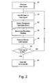
- Figures 2-4 show flow chart diagrams, explaining the steps of the method of the invention.
- the normal line of flow is from the top of the chart to the bottom thereof.
- Other flow directions are indicated by an arrow. Note that the steps disclosed may be performed at one or both the user equipment of the calling and called party or at equipment forming part of the telecommunications network.
- the type of tone signal received is identified, as schematically shown by block 31 "Identify type of tone signal".
- the type of tone signal may be identified in several ways. In the case of a signalling tone signal, sometimes dialling information provided by the calling party may be used.
- Characteristics of the tone signal such as the durations of the pulses and pauses, i.e. the rhythm of the tone, and the frequency or frequencies of the pulses, for example, provide the most reliable information for tone type detection. It will be appreciated that in the case of fax or modem tone signals to be identified, one may identify the type of user equipment, i.e. fax, modem, etc. from characteristics of the tone signal received.
- Equipment for analysing dialling information and/or determining pulse and pause duration and frequencies in a received tone signal is as such known to the skilled person and needs no further elucidation.
- bandstop and bandpass filters are selected based on the identified type of tone signal, as indicated by block 32, "Select Bandpass/Bandstop filters". A skilled person will appreciate that selecting also comprises configuring or adjusting the bandpass and bandstop filters.
- bandpass/Bandstop filtering is applied to the received tone signal, as indicated by block 33 "Bandpass/Bandstop filtering".
- the bandpass and bandstop filters are selected or set based on the identified type of the received tone signal.
- the result of this step is a bandpass filtered tone signal and a bandstop filtered tone signal.
- the obtained bandpass filtered and a bandstop filtered tone signals are analysed such as whether the signals received are indeed tone signals, whether the received signal is above a noise floor, the frequency of the tone or tones making up the tone signal, and others.
- This is schematically indicated by block 34, "Analyse filtered tone signals".
- the analysis result is provided to block 36, "Quantify tone signals", for providing a quantification of the received and analysed tone signal.
- the quantification provided may be a quality figure of the tone signal, for example, compared to an ideal tone signal, the properties of which may be stored in a repository 21, 22, for example, see figure 1 .
- the quantification may also be a quality figure of the communication link or of the device used in the telecommunication network for receiving, or sending, the tone signal, for example a user equipment, a radio access device or a network node.
- the steps 31 - 34 are performed on a received tone signal 30 as long as the tone signal is available, i.e. answer "No” of comparison block 35 "Tone signal ended?".
- the quantification in block 36 is performed on all the analysis results gathered, once the tone signal stopped, i.e. answer "Yes” of comparison block 35.
- Figure 3 shows an embodiment, according to the invention, for identifying the received tone signal, i.e. block 31 of figure 2 , by its frequency characteristics, applying digital signal analysing techniques.
- Block 40 identifies receipt of a tone signal, i.e. "Receive tone signal”. This block is identical to block 30 shown in figure 2 .
- the received tone signal is divided in frames of, preferably, equal duration, for example frames of 20 ms long.
- Block 41 "Divide tone signal in frames”.
- Each frame of the tone signal is subjected to DC and bandpass filtering.
- bandpass filters are used, ranging from 10-40 Hz, 25-75 Hz, 110-150 Hz and 375-505 Hz , respectively.
- bandpass filters can be provided as two-sections active biquad filters, for example.
- other bandpass filters will be used.
- the DC an bandpass filtered frames of the received tone signal are digitized and subjected to a Discrete Fourier Transform (DFT) analysis, for computing the frequency components of the tone signal.
- DFT Discrete Fourier Transform
- the spectral power distribution of the DFT analysis result is computed, providing a spectral power distribution over the frequency bands of the applied bandpass filtering.
- the step of DFT analysis and computation of the spectral power distribution are represented by a single block, i.e. block 43 "Compute spectral power distribution". This to indicate that other techniques may be used for computing the spectral power distribution of the frames of the received tone signal.
- Block 44 "Identify position of peaks in spectral power distribution".
- the threshold for identifying spectral power peaks may be dynamically set, by calculating an average spectral power of the signal with respect to a particular frequency band and setting the threshold to the calculated average value or at multiple thereof.
- the threshold may also be computed, for example, relative to the maximum spectral power peak value in the received tone signal by setting the threshold to a predetermined fraction of this maximum, for example at 25% of the maximum. Of course, other settings are possible.
- Block 45 "Store spectral power peak profile of tone signal”.
- the type of the received tone signal is identified among stored types of tone signals, i.e. their spectral power peak profile or distribution.
- Comparison block 46 "Profile known?".
- the known peak profiles may be stored in any of the repositories 21 and 22, for example, see figure 1 .
- the type of the received tone signal i.e. the ideal characteristics or properties thereof, can be retrieved from a repository 21, 22 for the purpose of applying appropriate bandpass/bandstop filtering, i.e. block 32 in figure 2 , according to the present invention.
- block 47 This is schematically indicated by block 47, "Retrieve type of tone signal".
- the received tone signal is not identified as a stored known type of tone signal, the received tone signal, i.e. its peak profile, is stored as a new type of tone signal in any or all of the repositories 21, 22, such as indicated by block 48 "Store profile as new type of tone signal".
- identification, profile forming and comparison may be performed using a suitably programmed digital processing device and memory.
- the frames of block 41 are temporarily stored and delayed in a frame delay buffer for the time required to identify the type of tone signal from a frame, before providing the frames to the selection and bandpass/bandstop filtering, i.e. blocks 32 and 33 in figure 2 .
- This delay is schematically indicated in figure 3 by block 49, "Delay frames".
- Figure 4 shows the processing steps of an embodiment of the invention for applying bandpass and bandstop filtering and analysis of the received tone signal, i.e. blocks 33 and 35 as shown in figure 2 , respectively.
- the delayed digital frames of the tone signal are fetched from the delay buffer of block 49 of figure 3 .
- Block 50 in figure 4 "Retrieve delayed frames”. Further, the identified type of the tone signal is retrieved, block 51 "Retrieve type of tone signal”.
- the identified type of tone signal is used as a basis for selecting the bandpass and bandstop filtering, as indicated by block 52, "Select Bandpass/Bandstop filters".
- the retrieved frame is then subjected to bandpass and bandstop filtering, block 53 "Bandpass/Bandstop filtering". See also block 33 of figure 2 .
- the parameters of the applied filtering are set based on the identified type of the tone signal.
- the bandpass and bandstop filters are steep digital filters, carefully designed to have a fast settling time.
- the results of the bandpass and bandstop filtering in block 53 are a bandpass filtered frame of the received tone signal and a bandstop filtered frame of the received tone signal.
- the bandpass filtered frame reflects the amount in which the received tone signal matches the ideal tone signal according to the identified type.
- the bandstop filtered frame contains all signal components which, in fact, should not be present when compared to the ideal tone signal according to the type of tone signal identified.
- comparison block 54 "Frame is voiced ?". In the affirmative, i.e. answer "Yes" of the comparison, the signal power of the frame is calculated, block 55 "Calculate power of frame". If the calculated power is less than a set value, for example -35 dB, the calculated power is set as a noise floor. Block 56, "Set noise floor”.
- a voiced frame indicates an amount of cross-talk, for example.
- Suitable digital processing algorithms for checking whether the frame contains voiced data and calculating the signal power of the frame are known to the skilled person. For the purpose of the present invention, these algorithms are not further described here.
- Block 57 "Calculate peak power and average power of bandstop and bandpass filtered frames".
- the above computations are applied at all or a plurality of frames of the received tone signal.
- the received tone signal is quantified in accordance with block 36 of figure 2 .
- the analysis result is judged with respect to the peak power over a plurality of frames, the average power over a plurality of frames, the ratio of the computed bandstop and bandpass peak power, the ratio of the computed bandstop and bandpass average power, and the value of the computed noise floor.
- a quality indication of the received tone signal is computed having a value ranging from 0-100. This value is called the RTQ value.
- An RTQ value of 100 indicates that an ideal tone signal has been received.
- An RTQ value equal to zero indicates the utmost bad quality.
- the received tone signal may be qualified from the worst quantifications of the tone signal.
- the received tone signal may be comprised of a sequence of tone signal bursts.
- the above discussed steps are applied to each tone signal burst of a plurality of tone signal bursts of the sequence of tone signal bursts. From the quantifications of the several bursts, a final quality value can be calculated as disclosed above.
- ringback tone signals for example, network operators sometimes generate a few bursts of a ringback tone signal from the local network equipment to which the user equipment of the calling party connects before transferring the actual ringback tone signal bursts received from the remote network devices to which the called party connects.
- a first few of the received bursts of the tone signal may be excluded from the quantification in block 36 of figure 2 .
- the digital processing equipment processing equipment (processors, buffers, etc.) and filters can be implemented in user equipment and/or network devices of the telecommunication network 1, as schematically indicated in figure 1 by reference numerals 23-24, 25-28, respectively.
- the several network devices 6, 7, 9, 10 may be controlled for excluding transmission lines providing a bad quality and/or to select particular routes or telecommunications links providing a desired quality, for example.
Landscapes
- Engineering & Computer Science (AREA)
- Signal Processing (AREA)
- Telephonic Communication Services (AREA)
Applications Claiming Priority (1)
| Application Number | Priority Date | Filing Date | Title |
|---|---|---|---|
| NL1037238A NL1037238C2 (en) | 2009-08-31 | 2009-08-31 | A method of and a device for quantifying a tone signal received in a telecommunications network. |
Publications (1)
| Publication Number | Publication Date |
|---|---|
| EP2290936A1 true EP2290936A1 (fr) | 2011-03-02 |
Family
ID=42021633
Family Applications (1)
| Application Number | Title | Priority Date | Filing Date |
|---|---|---|---|
| EP10008914A Withdrawn EP2290936A1 (fr) | 2009-08-31 | 2010-08-27 | Procédé et appareil pour quantifier un signal sonore reçu dans un réseau de télécommunication |
Country Status (3)
| Country | Link |
|---|---|
| US (1) | US8223928B2 (fr) |
| EP (1) | EP2290936A1 (fr) |
| NL (1) | NL1037238C2 (fr) |
Families Citing this family (5)
| Publication number | Priority date | Publication date | Assignee | Title |
|---|---|---|---|---|
| US10257591B2 (en) * | 2016-08-02 | 2019-04-09 | Pindrop Security, Inc. | Call classification through analysis of DTMF events |
| US12087319B1 (en) | 2019-10-24 | 2024-09-10 | Pindrop Security, Inc. | Joint estimation of acoustic parameters from single-microphone speech |
| JP2023511104A (ja) * | 2020-01-27 | 2023-03-16 | ピンドロップ セキュリティー、インコーポレイテッド | ディープ残差ニューラルネットワークを用いたロバストなスプーフィング検出システム |
| JP7716420B2 (ja) | 2020-03-05 | 2025-07-31 | ピンドロップ セキュリティー、インコーポレイテッド | 音声からの識別及び照合のための話者非依存性埋め込みのシステム及び方法 |
| US12488072B2 (en) | 2020-04-15 | 2025-12-02 | Pindrop Security, Inc. | Passive and continuous multi-speaker voice biometrics |
Citations (3)
| Publication number | Priority date | Publication date | Assignee | Title |
|---|---|---|---|---|
| JPS57147340A (en) * | 1981-03-07 | 1982-09-11 | Anritsu Corp | Measurement system for transmission characteristics |
| US6154537A (en) * | 1998-05-04 | 2000-11-28 | Motorola, Inc. | Method and apparatus for reducing false ringback detection |
| US20030071634A1 (en) * | 2001-10-16 | 2003-04-17 | Johnson Darrell J. | Tone generator and probe |
Family Cites Families (4)
| Publication number | Priority date | Publication date | Assignee | Title |
|---|---|---|---|---|
| NL169808B (nl) * | 1951-05-23 | Philips Nv | Frequentiekiezer met vrijloopkoppeling. | |
| JPS62204652A (ja) * | 1986-03-04 | 1987-09-09 | Nec Corp | 可聴周波信号識別方式 |
| US5905785A (en) * | 1996-08-07 | 1999-05-18 | Lucent Technologies Inc. | Detecting high usage telecommunications lines |
| US7035293B2 (en) * | 2001-04-18 | 2006-04-25 | Broadcom Corporation | Tone relay |
-
2009
- 2009-08-31 NL NL1037238A patent/NL1037238C2/en not_active IP Right Cessation
-
2010
- 2010-08-27 EP EP10008914A patent/EP2290936A1/fr not_active Withdrawn
- 2010-08-31 US US12/872,118 patent/US8223928B2/en not_active Expired - Fee Related
Patent Citations (3)
| Publication number | Priority date | Publication date | Assignee | Title |
|---|---|---|---|---|
| JPS57147340A (en) * | 1981-03-07 | 1982-09-11 | Anritsu Corp | Measurement system for transmission characteristics |
| US6154537A (en) * | 1998-05-04 | 2000-11-28 | Motorola, Inc. | Method and apparatus for reducing false ringback detection |
| US20030071634A1 (en) * | 2001-10-16 | 2003-04-17 | Johnson Darrell J. | Tone generator and probe |
Also Published As
| Publication number | Publication date |
|---|---|
| US8223928B2 (en) | 2012-07-17 |
| NL1037238C2 (en) | 2011-03-03 |
| US20110051905A1 (en) | 2011-03-03 |
Similar Documents
| Publication | Publication Date | Title |
|---|---|---|
| US7573825B2 (en) | Methods, apparatus and computer program products for testing a voice over Internet protocol communication system | |
| US20190231233A1 (en) | Hearing test and modification of audio signals | |
| EP1892920B1 (fr) | Système et procédé de surveillance pour passerelle de tronc | |
| US5479473A (en) | Method and apparatus for testing call paths over long distance carrier networks | |
| US5267300A (en) | High speed digital data transmission over switched voice network | |
| EP0720396A2 (fr) | Procédé et dispositif pour le réacheminement d'appels téléphoniques | |
| US5491744A (en) | Selective call waiting | |
| US6631183B1 (en) | Operating mode dependent greeting message | |
| US8223928B2 (en) | Method of and a device for quantifying a tone signal received in a telecommunications network | |
| WO2004082300A3 (fr) | Procede et appareil permettant d'etablir le numero d'abonne mobile pour des abonnes ayant la meme identite de ligne appelante | |
| US8737571B1 (en) | Methods and apparatus providing call quality testing | |
| EP2288199A1 (fr) | Procédé de collecte d'informations de communication, procédé de test et équipement côté réseau | |
| US20030227870A1 (en) | Method and system for automated voice quality statistics gathering | |
| CN1127814C (zh) | 电话系统中的动态回声消除器及参数选择 | |
| CN1147326A (zh) | 处理呼叫冲突的方法 | |
| US20070147342A1 (en) | Enhanced circuit-switched media transmission over ip access networks | |
| JPH11196178A (ja) | レベル自動調整装置 | |
| EP1952548B1 (fr) | Methode et appareil pour ameliorer une qualite d'appel | |
| US7885402B2 (en) | Gain control | |
| JP3136277B2 (ja) | 反響除去システム | |
| US9338303B2 (en) | Wireless enterprise congestion management | |
| JP4827351B2 (ja) | 網間の回線レベル調整方法及びシステム | |
| US6510180B1 (en) | Embedded software negotiation of PCM companding format | |
| CN101207650B (zh) | 音量调节和静音方法 | |
| EP1216519B1 (fr) | Mesure de la qualite perceptive de signaux vocaux comprenant des perturbations dues aux echos |
Legal Events
| Date | Code | Title | Description |
|---|---|---|---|
| PUAI | Public reference made under article 153(3) epc to a published international application that has entered the european phase |
Free format text: ORIGINAL CODE: 0009012 |
|
| AK | Designated contracting states |
Kind code of ref document: A1 Designated state(s): AL AT BE BG CH CY CZ DE DK EE ES FI FR GB GR HR HU IE IS IT LI LT LU LV MC MK MT NL NO PL PT RO SE SI SK SM TR |
|
| AX | Request for extension of the european patent |
Extension state: BA ME RS |
|
| 17P | Request for examination filed |
Effective date: 20110901 |
|
| STAA | Information on the status of an ep patent application or granted ep patent |
Free format text: STATUS: THE APPLICATION IS DEEMED TO BE WITHDRAWN |
|
| 18D | Application deemed to be withdrawn |
Effective date: 20160301 |