EP2291148B1 - Laterales abstandsglied für einen wirbelfortsatz - Google Patents
Laterales abstandsglied für einen wirbelfortsatz Download PDFInfo
- Publication number
- EP2291148B1 EP2291148B1 EP09735520.0A EP09735520A EP2291148B1 EP 2291148 B1 EP2291148 B1 EP 2291148B1 EP 09735520 A EP09735520 A EP 09735520A EP 2291148 B1 EP2291148 B1 EP 2291148B1
- Authority
- EP
- European Patent Office
- Prior art keywords
- implant
- spinous processes
- support portion
- end portion
- adjacent
- Prior art date
- Legal status (The legal status is an assumption and is not a legal conclusion. Google has not performed a legal analysis and makes no representation as to the accuracy of the status listed.)
- Active
Links
Images





Classifications
-
- A—HUMAN NECESSITIES
- A61—MEDICAL OR VETERINARY SCIENCE; HYGIENE
- A61B—DIAGNOSIS; SURGERY; IDENTIFICATION
- A61B17/00—Surgical instruments, devices or methods
- A61B17/56—Surgical instruments or methods for treatment of bones or joints; Devices specially adapted therefor
- A61B17/58—Surgical instruments or methods for treatment of bones or joints; Devices specially adapted therefor for osteosynthesis, e.g. bone plates, screws or setting implements
- A61B17/68—Internal fixation devices, including fasteners and spinal fixators, even if a part thereof projects from the skin
- A61B17/70—Spinal positioners or stabilisers, e.g. stabilisers comprising fluid filler in an implant
- A61B17/7062—Devices acting on, attached to, or simulating the effect of, vertebral processes, vertebral facets or ribs ; Tools for such devices
- A61B17/7068—Devices comprising separate rigid parts, assembled in situ, to bear on each side of spinous processes; Tools therefor
-
- A—HUMAN NECESSITIES
- A61—MEDICAL OR VETERINARY SCIENCE; HYGIENE
- A61B—DIAGNOSIS; SURGERY; IDENTIFICATION
- A61B17/00—Surgical instruments, devices or methods
- A61B17/02—Surgical instruments, devices or methods for holding wounds open, e.g. retractors; Tractors
- A61B17/025—Joint distractors
-
- A—HUMAN NECESSITIES
- A61—MEDICAL OR VETERINARY SCIENCE; HYGIENE
- A61B—DIAGNOSIS; SURGERY; IDENTIFICATION
- A61B17/00—Surgical instruments, devices or methods
- A61B17/56—Surgical instruments or methods for treatment of bones or joints; Devices specially adapted therefor
- A61B17/58—Surgical instruments or methods for treatment of bones or joints; Devices specially adapted therefor for osteosynthesis, e.g. bone plates, screws or setting implements
- A61B17/68—Internal fixation devices, including fasteners and spinal fixators, even if a part thereof projects from the skin
- A61B17/70—Spinal positioners or stabilisers, e.g. stabilisers comprising fluid filler in an implant
- A61B17/7062—Devices acting on, attached to, or simulating the effect of, vertebral processes, vertebral facets or ribs ; Tools for such devices
-
- A—HUMAN NECESSITIES
- A61—MEDICAL OR VETERINARY SCIENCE; HYGIENE
- A61B—DIAGNOSIS; SURGERY; IDENTIFICATION
- A61B17/00—Surgical instruments, devices or methods
- A61B17/02—Surgical instruments, devices or methods for holding wounds open, e.g. retractors; Tractors
- A61B17/025—Joint distractors
- A61B2017/0256—Joint distractors for the spine
-
- A—HUMAN NECESSITIES
- A61—MEDICAL OR VETERINARY SCIENCE; HYGIENE
- A61B—DIAGNOSIS; SURGERY; IDENTIFICATION
- A61B17/00—Surgical instruments, devices or methods
- A61B17/56—Surgical instruments or methods for treatment of bones or joints; Devices specially adapted therefor
- A61B2017/564—Methods for bone or joint treatment
-
- A—HUMAN NECESSITIES
- A61—MEDICAL OR VETERINARY SCIENCE; HYGIENE
- A61B—DIAGNOSIS; SURGERY; IDENTIFICATION
- A61B90/00—Instruments, implements or accessories specially adapted for surgery or diagnosis and not covered by any of the groups A61B1/00 - A61B50/00, e.g. for luxation treatment or for protecting wound edges
- A61B90/39—Markers, e.g. radio-opaque or breast lesions markers
- A61B2090/3966—Radiopaque markers visible in an X-ray image
-
- A—HUMAN NECESSITIES
- A61—MEDICAL OR VETERINARY SCIENCE; HYGIENE
- A61B—DIAGNOSIS; SURGERY; IDENTIFICATION
- A61B90/00—Instruments, implements or accessories specially adapted for surgery or diagnosis and not covered by any of the groups A61B1/00 - A61B50/00, e.g. for luxation treatment or for protecting wound edges
- A61B90/39—Markers, e.g. radio-opaque or breast lesions markers
-
- A—HUMAN NECESSITIES
- A61—MEDICAL OR VETERINARY SCIENCE; HYGIENE
- A61F—FILTERS IMPLANTABLE INTO BLOOD VESSELS; PROSTHESES; DEVICES PROVIDING PATENCY TO, OR PREVENTING COLLAPSING OF, TUBULAR STRUCTURES OF THE BODY, e.g. STENTS; ORTHOPAEDIC, NURSING OR CONTRACEPTIVE DEVICES; FOMENTATION; TREATMENT OR PROTECTION OF EYES OR EARS; BANDAGES, DRESSINGS OR ABSORBENT PADS; FIRST-AID KITS
- A61F2/00—Filters implantable into blood vessels; Prostheses, i.e. artificial substitutes or replacements for parts of the body; Appliances for connecting them with the body; Devices providing patency to, or preventing collapsing of, tubular structures of the body, e.g. stents
- A61F2/02—Prostheses implantable into the body
- A61F2/30—Joints
- A61F2002/30001—Additional features of subject-matter classified in A61F2/28, A61F2/30 and subgroups thereof
- A61F2002/30003—Material related properties of the prosthesis or of a coating on the prosthesis
- A61F2002/3006—Properties of materials and coating materials
- A61F2002/3008—Properties of materials and coating materials radio-opaque, e.g. radio-opaque markers
-
- A—HUMAN NECESSITIES
- A61—MEDICAL OR VETERINARY SCIENCE; HYGIENE
- A61F—FILTERS IMPLANTABLE INTO BLOOD VESSELS; PROSTHESES; DEVICES PROVIDING PATENCY TO, OR PREVENTING COLLAPSING OF, TUBULAR STRUCTURES OF THE BODY, e.g. STENTS; ORTHOPAEDIC, NURSING OR CONTRACEPTIVE DEVICES; FOMENTATION; TREATMENT OR PROTECTION OF EYES OR EARS; BANDAGES, DRESSINGS OR ABSORBENT PADS; FIRST-AID KITS
- A61F2250/00—Special features of prostheses classified in groups A61F2/00 - A61F2/26 or A61F2/82 or A61F9/00 or A61F11/00 or subgroups thereof
- A61F2250/0058—Additional features; Implant or prostheses properties not otherwise provided for
- A61F2250/0096—Markers and sensors for detecting a position or changes of a position of an implant, e.g. RF sensors, ultrasound markers
- A61F2250/0098—Markers and sensors for detecting a position or changes of a position of an implant, e.g. RF sensors, ultrasound markers radio-opaque, e.g. radio-opaque markers
-
- A—HUMAN NECESSITIES
- A61—MEDICAL OR VETERINARY SCIENCE; HYGIENE
- A61M—DEVICES FOR INTRODUCING MEDIA INTO, OR ONTO, THE BODY; DEVICES FOR TRANSDUCING BODY MEDIA OR FOR TAKING MEDIA FROM THE BODY; DEVICES FOR PRODUCING OR ENDING SLEEP OR STUPOR
- A61M29/00—Dilators with or without means for introducing media, e.g. remedies
Definitions
- the present invention is generally directed to intervertebral or interspinous process implants, systems and kits including such implants, methods of inserting such implants, and methods of treating spinal stenosis or for alleviating pain or discomfort associated with the spinal column.
- spinal stenosis is the narrowing of the spinal canal, lateral recess or neural foramen, characterized by a reduction in the available space for the passage of blood vessels and nerves.
- Clinical symptoms of spinal stenosis include extremity pain, radiculopathy, sensory or motor deficit, bladder or bowel dysfunction, and neurogenic claudication. Pain associated with such stenosis can be relieved by surgical or non-surgical treatments, such as medication, physical therapy, back braces and the like. While spinal stenosis is generally more prevalent of the elderly, it can occur in individuals of all ages and sizes.
- Some embodiments of the present invention are directed to minimally invasive implants, in particular, interspinous process spacers.
- Implants in accordance with the invention may come in many shapes and sizes.
- the illustrative embodiments provided herein-below provide guidance as to the many types of implants that may be advantageously used in accordance with the present invention.
- the implants are adapted such that their insertion technique (including methods of the present invention) is minimally invasive, and generally simpler, and/or safer than those installed in open or more invasive techniques.
- implants according to the present invention may be advantageously inserted into a patient as an out-patient procedure.
- Embodiments of the present invention include implants adapted to be placed between first and second adjacent spinous processes.
- the implants may be adapted such that after insertion of an implant into a patient, a portion of the implant maintains a desired amount of distraction or spacing between two adjacent spinous processes.
- the implants or portions thereof that substantially maintain a desired spacing between spinous processes are also referred to herein as "spacers.”
- the implants may include spinous process support surfaces, indented portions or saddle portions spaced apart by a distance (a) ( FIG. 4 ), which generally corresponds to a desired distance for distraction or spacing of two adjacent spinous processes.
- Other embodiments similarly provide a desired distance for distraction or spacing of two adjacent spinous processes.
- the desired distraction or spacing distance may vary somewhat after insertion, for example if a patient moves its spine into a position that causes further distraction.
- the implant may be resiliently compressible or expandable in the cranial-caudal direction such that the implant may support and or adjust to dynamic movement of the spine.
- embodiments of the present invention may be extended to provide distraction or spacing of more than two adjacent spinous processes.
- Implants according to the present invention may be adapted to be inserted between a first and second spinous process at any region in the spine.
- typically implants according to the present invention may be inserted in the lumbar region, it is contemplated that it is possible to configure inserts according to the present invention for insertion into other regions such as for example, the thoracic or cervical region.
- implants according to the invention may have varying profiles when viewed in a saggital or axial plane.
- the implants can have varied cross-sectional shapes to conform to the varied anatomical shapes of the interspinous spaces of the spine.
- implants of the invention may secure themselves in place without a supplemental attachment mechanism or fastening device attached directly to a spinous process or other portion of the spine.
- implants in accordance with the invention may be attached to one or more spinous processes or other portion of the spine, or may attach to itself in such a manner as to secure the implant between two adjacent spinal processes.
- implants in accordance with the present invention may be attached to one or both spinous processes or other portion of the spine by one or more pins, screws, wires, cables, straps, surgical rope, sutures, elastic bands, or other fastening devices.
- Other exemplary implants, attachment mechanisms, and methods are disclosed in U.S. Patent Application Serial Nos. 11/366,388 and 11/691,357 . "Securing" implants between spinous processes, does not require that the implant not move at all, but rather means that the implant does not move so far away from between the spinous processes that it does not perform the function of maintaining a desired distraction distance or space between the adjacent spinous processes.
- Implants in accordance with the present invention may be secured between spinous processes by methods other than using a fastening device.
- implants in accordance with the present invention may be secured in place with respect to spinous processes by mechanical forces resulting from the design of the implant, including the shape itself.
- Exemplary implants may also be secured to spinous processes, by surface modifications to portions of the implant, such as to create frictional forces or other bonds between the implant and spinous processes.
- Such surface modifications may include mechanical modifications to the surface and/or one or more coatings.
- Exemplary coatings which may be utilized include, but are not limited to, titanium plasma sprays and chrome sprays or the like. Such mechanical forces and/or surface modifications may be utilized in addition to, or in place of various other attachment methods described herein.
- implant 10 for creating, increasing, or maintaining distraction between adjacent spinous processes.
- implant 10 is adapted and configured to be placed between adjacent spinous processes.
- FIGS. 33-34 a posterior and side view, respectively, of implant 10 is shown in implanted positions between to two adjacent spinous processes 5.
- implant 10 generally comprises an elongate member extending laterally along axis 12 from a first lateral end 14 to a second lateral end 16.
- implant 10 may be cannulated with a central cannula or opening 18 extending along axis 12.
- implant 10 may be solid and without a cannulation and in this regard may be advanced or inserted by a practitioner without the use of a guidewire.
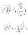
- implant 10 may comprise a unitary body with a general barbell-like or spade-like shape, and generally includes a first end portion or distraction portion 20 adjacent first end 14, a second end portion or trailing end portion 22 adjacent second end 16 and a central support portion or saddle portion 24 disposed between the distraction and trailing end portions 20, 22.
- a radio-opaque marker 29 may extend through a portion of implant 10. As best seen in FIG.
- support portion 24 may have a height (a) and width (d), and the implant may have an overall length (e).
- implant 10 has a generally arrow or spade shaped profile or perimeter when viewed perpendicular to axis 12 and distraction portion 20 is generally flatter or narrower when viewed from the side, as shown in FIG. 4 .
- Distraction portion 20 is generally configured and dimensioned to facilitate lateral insertion between adjacent spinous processes.
- distraction portion 20 generally comprises a frustoconical, wedged, or tapered shape widening along axis 12 from a tip 26 adjacent the first end 14 to a shoulder 28 adjacent central support portion 24.
- the distraction portion 20 resembles a generally flattened spear head that tapers greater in a lateral direction than in vertical direction.
- portion 20 is generally tapered along a cone angle 30 in a lateral direction and cone angle 30 may be between about 10 and 65 degrees. Also, as best seen in FIG.
- portion 20 is generally ramped or tapered along a cone angle 31 in a vertical direction and cone angle 31 may be between about 1 and 65 degrees.
- cone angle 30 may be between about 30 and 80 degrees
- cone angle 31 may be between about 5 and 30 degrees.
- distraction portion 20 may additionally include a ramped, wedged, fluted, grooved, a cam or cam-like profile section 32 intermediate the tip 26 and shoulder 28.
- the ramped section 32 and more gradual taper in the vertical direction facilitates lateral insertion with the generally flatter dimension positioned between the adjacent spinous processes.
- distraction portion 20 is configured and dimensioned such that when implant 10 is advanced between adjacent spinous processes laterally along axis 12, the adjacent spinous processes engage or ride upon ramp section 32 and are distracted or separated apart as implant 10 is advanced laterally along axis 12 during implantation.
- the rate at which the distraction occurs may be readily controlled by a surgeon by controlling the rate of lateral advancement of implant 10, so that the surgeon may advance implant 10 along axis 12 as slow or as fast as desired.
- implant 10 may be characterized as self-distracting, as the implant itself distracts or separates the spinous processes as it is being implanted, i.e . without requiring an additional distraction step or device.
- Trailing end portion 22 adjacent second end 16 may comprise a flange and/or generally frustoconical, wedged, or tapered shape narrowing along axis 12 from a major dimension 38 adjacent central support portion 24 to a minor dimension 40 adjacent the second end 16.
- trailing end portion 22 may comprise a flange portion 39 that extends circumferentially about central support portion 24.
- flange portion 39 may extend around a majority of the circumference of support portion 24, and in one embodiment, best seen in FIG. 4 , flange 39 may be generally flatter along the bottom section.
- trailing end portion 22 may comprise a tapered portion 41 that may be generally symmetrical to distraction portion 20 with generally similar lateral length and cone angle 31. In alternate embodiments, however, the trailing end portion 22 need not be symmetrical whatsoever and may have any shape irrespective of the dimension of distraction portion 20.
- a socket or indentation 42 may be provided to receive an installation or driving tool with a correspondingly shaped driver tool.
- Any known driving tools and engagement means may be used, including but not limited to, a flat driver, a star shaped driver, a threaded driver, or a custom shaped driver, among others.
- a driver 43 may be provided with an external shape configured to fit within socket 42.
- driver 43 may comprise a flexible shaft such that the implant 10 may travel along a curved or arcuate path.
- a flexible driver configuration may facilitate insertion of an implant in the L5-S1 region of the spine where direct lateral insertion may be more difficult. As best seen in FIG.
- indent 42 may be concentric with cannula 18 to facilitate insertion with a cannulated driver tool over a guidewire extending through cannula 18 and indentation 42.
- a threaded section may be provided internal to indentation 42 to accommodate a threaded connection of an installation or removal tool ( FIG. 26 ) with implant 10.
- the threaded connection between a tool and the implant facilitates a laterally fixed relative connection between the implant and tool so that the implant does not dislodge from the trailing end and may efficiently transfer both lateral translational and rotational forces applied on the tool to the implant during installation.
- the threaded connection may also facilitate the removal of implant 10 from the body of a patient should a surgeon so desire.
- Central support portion 24 is provided between the distraction and trailing end portions 20, 22.
- support portion 24 may have a diameter or height (a) less than the major dimensions 28, 38 of portions 20, 22.
- implant 10 when viewed from the top, as seen in FIG. 3 , implant 10 may appear to have a general H-like shape or a barbell-like shape, with the lateral sides 20, 22, being longitudinally spaced a distance 23, 25, respectively beyond central support portion 24. In one variation, distances 23, 25 do not need to be equal.
- lateral sides 20, 22 may be spaced a distance 23, 25 between about 1mm and about 6mm from the support portion 24. In one particular embodiment, distances 23, 25 is about 4-5 mm.
- a small transition bump 27 or height differential may be provided at the transition from the distraction portion 20 to the central support portion 24.
- bump 27 may have a height of about 1 mm.
- a smooth transition may be provided without a bump or height differential.
- a flexible bumper member or sleeve may be positioned about support portion so as to be flush with distraction portion 20 when viewed from the side.
- Implant 10 is configured and dimensioned to facilitate rotation of about 90 degrees into a second or higher profile position upon implantation and once distraction portion 20 has passed laterally beyond the spinous processes.
- the transition from the distraction portion 20 to the central support portion 24 and the transition from the central support portion 24 to trailing end portion 22 may be abrupt.
- a shoulder wall section 44 may be formed at either end of central support portion 24, and when implant 10 is implanted, wall sections 44 may serve to limit or block movement of the implant along axis 12 and/or dislodgement from the interspinous space.
- textures such as knurling, serrations, abrasions, or other similar features may be provided along the surface of central support portion 24 to facilitate gripping or frictional contact with bone, such as the spinous process, to limit or reduce movement and/or dislodgement from the interspinous space once installed.
- one or more barbs 46 may extend from wall sections 44. Barbs 46 may have a saw-tooth shape, have an angled undercut, or may have other sharpened end portions to grip and/or engage tissue or bone to resist counter rotation of implant 10. According to one variation, two barbs 46 may be radially spaced about the perimeter of a wall section 44, however, in alternate embodiments more or less barbs may be provided as desired.
- the geometry and spacing of the barbs may be varied between each wall or along an individual wall section 44.
- barbs 46 may be configured and dimensioned to limit or reduce rotational, twisting, and/or lateral movement of implant 10 with respect to spinous processes when installed.
- the wall sections 44 may have a star grind surface feature to limit rotational movement when installed.
- one or more protrusions or spikes may be provided along central portion 24 and may extend radially outward to engage the spinous process.
- all or a portion of implant 10 may be resiliently compressible or expandable in the cranial-caudal direction such that the implant may support and or adjust to dynamic movement of the spine.
- central support portion 24 may include a flexible bumper member to at least partially cushion the compression of adjacent spinous processes.
- the bumper member may comprise a cylindrical sleeve provided to extend around the periphery of central support portion 24.
- the bumper member may be integrated into the support portion and in alternate embodiments the bumper member may be fit over the support portion.
- the bumper member may be made from biocompatible polyurethane, polycarbonate-urethane, elastomer, or other similar material.
- implant 10 may be made from varying materials along its length, such that for example the central support portion may be made from a resilient material, such as polyurethane, polycarbonate-urethane, elastomer or the like, and the end portions may be made from a rigid material, such as titanium or the like.
- a resilient material such as polyurethane, polycarbonate-urethane, elastomer or the like
- the end portions may be made from a rigid material, such as titanium or the like.
- the implant itself may serve to dilate or distract the spinous processes as it is being inserted and/or after insertion.
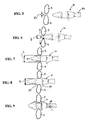
- the first end 14 of implant 10 may be initially inserted or advanced laterally between compressed adjacent spinous processes as shown in FIGS. 5-9 , for example.
- the supraspinous ligament is not removed.
- the adjacent spinous processes 5 may be compressed or narrowly spaced such that the initial space or longitudinal distance 50 between the processes may be about equal to or slightly larger or smaller than distance (b) of implant 10.
- one or more ramp surfaces or portions of the implant may contact one or both of the spinous processes 5 and may initially distract the processes a distance (b).
- the ramp 32 and/or the wedged or tapered shape of the distraction portion may distract the spinous processes further apart from one another, until the implant is advanced laterally into an implanted position ( FIGS. 8-9 ) and the spinous processes are fitted into the central support portion 24 of the implant 10.
- the ramp surfaces engage the adjacent spinous processes as the implant is laterally advanced to act or perform in a cam-like manner to translate the lateral force to separate the spinous processes in the longitudinal or cranial-caudal direction as the implant is advanced.
- the maximum distraction of spinous processes by the implant 10 is distance (c) depicted in FIG. 7 .
- distance (c) is greater than distance (a) such that the spinous processes 5 may be slightly "over distracted” during installation.
- an over distraction may facilitate enhanced tactile feedback to a surgeon during installation as the spinous processes drop into the central support portion to signify a desired lateral placement in the patient with the spinous processes positioned within the central support portion.
- the flange 39 of trailing end portion 22 may contact and/or abut the lateral side of the spinous processes to prevent further lateral translation and implant 10 may be subsequently rotated about one quarter turn or about 90 degrees into the final implantation position as shown in FIG. 9 .
- the shoulder wall sections 44 may contact the lateral sides of the spinous processes to limit or block movement of the implant along axis 12 and/or dislodgement from the interspinous space.
- the implant may maintain the spinous processes in a distracted or spaced condition, for example where the distance (a) of the implant is greater than a pre-implantation distance between the spinous processes.
- FIGS. 10-19 various alternative embodiments of two-piece implant assemblies are shown with the trailing end 22 detachably connectable to the central support portion 24.
- the implant assemblies may readily accommodate a flexible bumper member as described above.
- the bumper comprises a cylindrical sleeve
- the sleeve may be assembled over the central support portion prior to attaching the trailing end portion 22 to the central support portion 24.
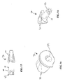
- FIGS. 10-13 one embodiment of an interspinous process implant assembly 60 is shown disassembled.
- Implant 60 is similar to implant 10 described above, however, in this embodiment implant 60 is an assembly of two pieces with the trailing end portion 22 threadably attachable to central support portion 24.
- external threading 62 may be provided on the proximal end of support portion 24 which may engage internal threading 64 provided on trailing end portion 22.
- a pin, set screw or other fixation element 66 may extend at least partially through the trailing end portion 22 and through opening 68 in support portion 24 to fixedly secure the central support portion 24 to the trailing end portion 22. In this regard, fixation element 66 prevents undesirable disassembly of assembly 60.
- FIGS. 14-16 an alternative two-piece implant 70 is shown with a bayonet type connection between the trailing end 22 and central support portion 24.
- bayonet type fingers 72 may be provided on the proximal end of support portion 24 which may engage internal bayonet feature 74 provided on trailing end portion 22 to connect the trailing end to the central support portion 24.
- FIGS. 17-19 an alternative two-piece implant 80 is shown with a snappable connection between the trailing end 22 and central support portion 24.
- prongs 82 may be provided on the proximal end of support portion 24 which may engage internal indentations provided on trailing end portion 22 to connect the trailing end to the central support portion 24.
- first portion 92 and second portion 94 are slidable with respect to each other along axis 12 or along the length of the implant.
- the first and second portions 92, 94 are interlockingly connected such as with a dovetail (or other inter locking shape) to allow one half of the implant to slide onto the other.
- first portion 92 in an initial position first portion 92 may be disposed proximally along axis 12 and second portion 94 may be disposed distally. As shown in FIG.
- second portion 21 may be slidingly advanced along axis 12 such as for example during implantation in the interspinous space.
- first portion 92 may be initially advanced into the interspinous space until the distraction portion 20 reaches the contralateral side of the spinous processes and the second portion 94 may subsequently be advanced into the interspinous space.
- implant 90 may cause less distraction of the interspinous space than an integral implant.
- a deflectable arm 96 may be provided on the first portion to snappably engage the second portion once the first portion has been slidingly advanced in the distal direction, as shown in FIGS. 22-23 .
- the two pieces 92, 94 of the implant interlock to form a solid implant when placed in the interspinous space.
- implant 90 has a generally similar profile to implant 10 described above.
- Kits having at least one implant such as those depicted in FIGS. 1-24 may include various sizes of implants having varying heights (a), widths (d), and overall lengths (e), for example having variations with incremental distances.
- a system or kit may be provided that has implants having heights (a) between about 6mm to about 22mm.
- implants having heights (a) of 8mm, 10mm, 12mm, 14mm, 16mm, 18mm, and 20mm may be provided.
- a system or kit may be provided that has implants having widths (d) between about 6mm to about 18mm.
- implants having widths (d) of 8mm, 12mm, and 16mm may be provided.
- a system or kit may be provided that has implants having overall lengths (e) between about 20mm and about 65mm.
- implants having overall lengths (e) of 25mm and 60mm may be provided.
- Implants in accordance with the present invention may be made of one or more materials suitable for implantation into the spine of a mammalian patient.
- Materials in accordance with the present invention may be biocompatible with a mammalian patient and/or may have one or more surface coatings or treatments that allow the spacers to be biocompatible.
- Materials in accordance with the present invention may include one or more materials having sufficient load capability and/or strength to maintain the desired spacing or distraction between spinous processes.
- certain embodiments may have components or portions made of a material having certain flexibility, as desired for the particular application.
- the materials of the present invention may be made of one or more materials that maintain their composition and shape for as long a time as possible without degrading or decomposing or changing shape, such that replacement of the implant is avoided.
- Suitable materials for use in accordance with the present invention would be known to those skilled in the art.
- Non-limiting examples include one or more materials selected from medical grade metals, such as titanium or stainless steel, biocompatible polymers, such as polyetheretherketone (PEEK), ceramics, deformable materials, bone, allograft, demineralized or partially demineralized bone, allograft ligament, polyurethane, and polycarbonate-urethane (for example, for portions of the insert where cushioning is desired).
- PEEK polyetheretherketone
- any fastening devices may be made of materials having one or more of the properties set forth with respect to the implant itself.
- screws or pins may include titanium and straps may include polyethylene.
- primarily radiolucent material may be used.
- radio-opaque material or markers may be used in combination with the radiolucent material to facilitate implantation.
- exemplary radio-opaque material includes but is not limited to titanium alloys, tantalum or other known radio-opaque marker material.
- implants in accordance with the present invention may have one or more portions that may have modified surfaces, surface coatings, and/or attachments to the surface, which may assist in maintaining the spacer in a desired position, for example by friction.
- Other embodiments of implants according to the invention may include hydrophilic and/or hydrophobic coatings or combinations thereof.
- all or part of an implant such as all or part of distraction portion 20, may have a hydrophilic coating to reduce friction and facilitate lateral insertion between bony parts.
- all or part of an implant such as all or part of central support portion 24, may have a hydrophobic coating to increase friction to deter dislodgement from between bony parts.
- Suitable surface modifications, coatings, and attachment materials would be known to those skilled in the art, taking into consideration the purpose for such modification, coating, and/or attachment.
- Methods are provided for treating spinal stenosis. Methods are also provided for inserting an implant. These methods may include implanting a device to create, increase, or maintain a desired amount of distraction, space, or distance between adjacent first and second spinous processes.
- the adjacent first and second spinal processes may be accessed by various methods known by practitioners skilled in the art, for example, by accessing the spinous processes from at least one lateral side/unilateral, bilateral, or midline posterior approach.
- Certain methods include creating an incision in a patient to be treated, dilating any interspinous ligaments in a position in which the implant is to be placed in the patient, sizing the space between adjacent spinous processes (for example using trials), and inserting an implant of the appropriate size between the adjacent spinous processes.
- Methods of the present invention may include securing the implant to one or more of the spinous processes, to one or more other portions of the patient's spine, and/or to itself such that the implant maintains its position between the spinous processes.
- Methods may include dilating or distracting the spinous processes apart from one another before sizing and/or before inserting the implant. Methods may vary depending on which implant is being inserted into a patient. For example, certain implants may require distracting the spinous processes apart before inserting the implant, while other implants may themselves dilate or distract the spinous processes while inserting the implant. In embodiments where the implants themselves dilate or distract the spinous process, the implant may have, for example, a predetermined shape to dilate, distract, or otherwise move or separate apart adjacent spinous processes such as a cam or cam-like profile, it may have a distraction device that is deployed, and/or it may have a tapered expander to distract an opening between the adjacent spinous processes or other features to facilitate distraction of the adjacent spinous processes.
- spacers may be placed between the spinous processes anterior to the supraspinous ligament, avoiding the nerves in the spinal canal.
- the procedure may be performed under local anesthesia.
- the patient may be placed in the right lateral decubitus position with the lumbar spine flexed or in another flexed position.
- a surgeon may desire to use fluoroscopy to align in parallel the adjacent vertebral bodies corresponding to the adjacent spinous processes to gauge the desired distraction distance.
- one or more probes may be used to locate the space between the spinous processes.
- the space may be widened, for example with a dilator before inserting the implant.
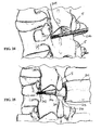
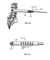
- FIGS. 24-32 one embodiment of a surgical method according to the invention for implanting an implant 10 in the spine is disclosed.
- the adjacent first and second spinal processes 5 may be accessed from one lateral side through a minimally invasive procedure.
- a unilateral approach may be used to install implant 10 without removal of the supraspinous ligament.
- a guide wire 202 such as a K wire, is inserted laterally through the skin and into the interspinous space 204.
- a working portal may be created concentric to the guidewire 202, as shown in FIGS.
- a series of sequentially larger diameter tubes 206, 208, 210, 212, 214 to dilate the tissue surrounding guidewire 202.
- the smaller diameter tubes 206, 208, 210, 212 may be withdrawn, leaving the guidewire 202 and the outer tube 214.
- one or more trials 215 may then be inserted to appropriately size the interspinous space 204 and the trials 215 may also be utilized to dilate interspinous ligaments.
- a generally cannulated cylindrical trial 215, shown in FIG 28 may be utilized to size the space between adjacent processes 5.
- a trial 216 that may be used is shown which may comprise a ramped tip portion 217 adjacent its distal end and multiple longitudinal indentations or markings 218 on at least a portion of central portion 219 and may provide visual indication when viewed under fluoroscopy of the width of the spinous processes and facilitate the surgeon's selection of an appropriately sized implant.
- the appropriate diameter of central portion 219 of trial 216 may be selected to gauge the amount of distraction desired.
- the spacing of the spinous processes may be viewed under fluoroscopy to facilitate the surgeon's selection of an appropriately sized implant.
- an implant of the appropriate size may be inserted between the adjacent spinous processes.
- Implant 10 is advanced laterally over guidewire 202 through cannulation 18 to the interspinous space 204.
- one or more ramp surfaces or portions of the implant may contact one or both of the spinous processes 5 and may initially distract the processes.
- Implant 10 may be laterally advanced along the guidewire to further advance implant 10 between the spinous processes and, the wedged or tapered shape of the distraction portion 20 may distract the spinous processes further apart from one another, until the implant is in an implanted position ( FIGS.
- the flange 39 of trailing end portion 22 may contact and/or abut the lateral side of the spinous processes to prevent further lateral translation and implant 10 may be subsequently rotated about one quarter turn or about 90 degrees into the final implantation position as shown in FIG. 32 .
- the shoulder wall sections 44 may contact the lateral sides of the spinous processes to limit or block movement of the implant along axis 12 and/or dislodgement from the interspinous space.
- the guidewire may be removed through the cannulation leaving the implant 10 in the interspinous space.
- Implant 90 is advanced laterally over guidewire 202 through cannulation 18 to the interspinous space 204.
- the first portion 92 may be initially advanced into the interspinous space until the distraction portion 20 reaches the contralateral side of the spinous processes.
- the second portion 94 may subsequently be advanced into the interspinous space.
- implant 90 may be subsequently rotated about one quarter turn or about 90 degrees into the final implantation position as shown in FIG. 41.
- the guidewire may be removed through the cannulation leaving the implant 10 in the interspinous space.
Landscapes
- Health & Medical Sciences (AREA)
- Orthopedic Medicine & Surgery (AREA)
- Surgery (AREA)
- Life Sciences & Earth Sciences (AREA)
- Neurology (AREA)
- Molecular Biology (AREA)
- Heart & Thoracic Surgery (AREA)
- Medical Informatics (AREA)
- Biomedical Technology (AREA)
- Animal Behavior & Ethology (AREA)
- General Health & Medical Sciences (AREA)
- Public Health (AREA)
- Veterinary Medicine (AREA)
- Engineering & Computer Science (AREA)
- Nuclear Medicine, Radiotherapy & Molecular Imaging (AREA)
- Prostheses (AREA)
Claims (19)
- Vorrichtung (10) zur Implantation in die Wirbelsäule, umfassend:- einen kanülierten Körper, umfassend einen Stützbereich (24), der sich längs einer Querachse (12) zwischen ersten (20) und zweiten (22) Endbereichen erstreckt, wobei der Körper eine Kanüle (18) definiert, die sich längs der Querachse (12) hindurch erstreckt;- wobei sich zumindest ein Teil des ersten Endbereichs (20) über den Stützbereich (24) in eine Richtung senkrecht zur Querachse erstreckt;- wobei die Vorrichtung (10) zum Einsetzen zwischen benachbarten Dornfortsätzen der Wirbelsäule in einer Seitenrichtung längs der Querachse konfiguriert und dimensioniert ist und über einen sich durch die Kanüle (18) erstreckenden Führungsdraht vorschiebbar ist; und- wobei der erste Endbereich (20) eine Rampe auf zumindest einem Teil einer Außenfläche aufweist, die beim Einsetzen zum Eingriff in die und Trennen der benachbarten Dornfortsätze und zum Vorschieben der Vorrichtung (10) in der Seitenrichtung konfiguriert und dimensioniert ist, um den Stützbereich (24) in einer vorgegebenen Position zwischen den Dornfortsätzen zu positionieren;- dadurch gekennzeichnet, dass der erste Endbereich (20) einen rampenförmigen Ablenkungsbereich aufweist, der sich längs der Achse (12) von einer zum ersten Ende (14) benachbarten Spitze (26) zu einer zum mittigen Stützbereich (24) benachbarten Schulter (28) erweitert, die zum Ablenken der Dornfortsätze angeordnet ist, wenn die Vorrichtung (10) implantiert wird;- wobei Schulter-Wandabschnitte (44), die an jedem Ende des Stützbereichs (24) ausgebildet sind, zum Berühren der seitlichen Seiten der Dornfortsätze konfiguriert sind, um eine Bewegung des Implantats im interspinalen Raum zu begrenzen oder zu blockieren.
- Vorrichtung nach Anspruch 1, wobei sich zumindest ein Teil des zweiten Endbereichs (22) über den Stützbereich (24) in eine Richtung senkrecht zur Querachse erstreckt.
- Vorrichtung nach Anspruch 1, wobei der Körper aus einem Polyetheretherketon-(PEEK-)Material hergestellt ist.
- Vorrichtung nach Anspruch 1, wobei der erste Endbereich (20) eine im Wesentlichen kegelstumpfförmige Form aufweist.
- Vorrichtung nach Anspruch 1, wobei der Stützbereich (24) zum Einpassen zwischen benachbarten Dornvorsätzen konfiguriert und dimensioniert ist und ferner umfasst: eine proximale Abstützfläche, die in Längsrichtung von einer distalen Abstützfläche durch einen ersten Abstand beabstandet ist, wobei die Abstützflächen zum Berühren von benachbarten Dornfortsätzen der Wirbelsäule konfiguriert sind, wobei der erste Abstand zum Beabstanden der beiden benachbarten Dornfortsätze vorgegeben ist, wenn die Vorrichtung in die Wirbelsäule implantiert ist.
- Vorrichtung nach Anspruch 1, wobei der Stützbereich (24) einen im Wesentlichen kreisförmigen Querschnitt aufweist.
- Vorrichtung nach Anspruch 1, wobei der Körper aus einem Titanmaterial hergestellt ist.
- Vorrichtung nach Anspruch 2, wobei ein Teil der Endbereiche (20, 22) zum Berühren der seitlichen Seite der Dornfortsätze konfiguriert und dimensioniert ist, wenn die Vorrichtung in der Wirbelsäule implantiert ist.
- Vorrichtung nach Anspruch 1, wobei der Körper konfiguriert und dimensioniert ist, um in-situ gedreht zu werden, um die ersten (20) und zweiten (22) Endbereiche auf gegenüberliegenden seitlichen Seiten der Dornfortsätze zu positionieren.
- vorrichtung nach Anspruch 1, wobei der erste Endbereich (20) eine kegelstumpfförmige Form aufweist.
- Vorrichtung nach Anspruch 1, wobei sich der erste Endbereich (20) entlang seiner Länge in Längsrichtung verjüngt.
- Vorrichtung nach Anspruch 1, wobei der Stützbereich (24) aus einem elastisch komprimierbaren und dehnbaren Material hergestellt ist.
- Vorrichtung nach Anspruch 1, wobei der erste Endbereich (20) eine Übergangserhebung (27) umfasst.
- Vorrichtung nach Anspruch 1, wobei der zweite Endbereich (22) einen Flanschbereich (39) umfasst.
- Vorrichtung nach Anspruch 1, wobei der erste Endbereich (20) eine oder mehrere Spitzen (46) umfasst, die sich aus einem Wandbereich (44) erstrecken.
- Vorrichtung nach Anspruch 15, wobei die Spitzen (46) Sägezähne sind.
- Vorrichtung nach Anspruch 1, wobei der zweite Endbereich (22) einen sich hindurch erstreckenden röntgenstrahlundurchlässigen Marker (29) umfasst.
- Vorrichtung nach Anspruch 1, wobei der zweite Bereich (22) ein flexibles, sich um zumindest einen Teil der Außenseite erstreckendes Element umfasst, um zumindest teilweise das Zusammendrücken von benachbarten Dornfortsätzen zu dämpfen.
- Vorrichtung nach Anspruch 18, wobei das flexible Element eine im Wesentlichen zylindrische Hülse aufweist, die aus einem biokompatiblen Polyurethanmaterial hergestellt ist.
Applications Claiming Priority (2)
| Application Number | Priority Date | Filing Date | Title |
|---|---|---|---|
| US12/107,222 US8523910B2 (en) | 2008-04-22 | 2008-04-22 | Lateral spinous process spacer |
| PCT/US2009/041344 WO2009132059A1 (en) | 2008-04-22 | 2009-04-22 | Lateral spinous process spacer |
Publications (3)
| Publication Number | Publication Date |
|---|---|
| EP2291148A1 EP2291148A1 (de) | 2011-03-09 |
| EP2291148A4 EP2291148A4 (de) | 2013-03-13 |
| EP2291148B1 true EP2291148B1 (de) | 2014-03-19 |
Family
ID=41201787
Family Applications (1)
| Application Number | Title | Priority Date | Filing Date |
|---|---|---|---|
| EP09735520.0A Active EP2291148B1 (de) | 2008-04-22 | 2009-04-22 | Laterales abstandsglied für einen wirbelfortsatz |
Country Status (3)
| Country | Link |
|---|---|
| US (4) | US8523910B2 (de) |
| EP (1) | EP2291148B1 (de) |
| WO (1) | WO2009132059A1 (de) |
Families Citing this family (36)
| Publication number | Priority date | Publication date | Assignee | Title |
|---|---|---|---|---|
| US9055981B2 (en) | 2004-10-25 | 2015-06-16 | Lanx, Inc. | Spinal implants and methods |
| US8241330B2 (en) | 2007-01-11 | 2012-08-14 | Lanx, Inc. | Spinous process implants and associated methods |
| US9265532B2 (en) | 2007-01-11 | 2016-02-23 | Lanx, Inc. | Interspinous implants and methods |
| US7842074B2 (en) | 2007-02-26 | 2010-11-30 | Abdou M Samy | Spinal stabilization systems and methods of use |
| US8142479B2 (en) * | 2007-05-01 | 2012-03-27 | Spinal Simplicity Llc | Interspinous process implants having deployable engagement arms |
| EP2142146A4 (de) | 2007-05-01 | 2010-12-01 | Spinal Simplicity Llc | Interspinöse implantate und verfahren zu ihrer implantation |
| US9173686B2 (en) * | 2007-05-09 | 2015-11-03 | Ebi, Llc | Interspinous implant |
| US9381047B2 (en) | 2007-05-09 | 2016-07-05 | Ebi, Llc | Interspinous implant |
| US9757164B2 (en) | 2013-01-07 | 2017-09-12 | Spinal Simplicity Llc | Interspinous process implant having deployable anchor blades |
| US8945184B2 (en) * | 2009-03-13 | 2015-02-03 | Spinal Simplicity Llc. | Interspinous process implant and fusion cage spacer |
| US9861399B2 (en) | 2009-03-13 | 2018-01-09 | Spinal Simplicity, Llc | Interspinous process implant having a body with a removable end portion |
| MX2011010375A (es) | 2009-03-31 | 2012-02-23 | Lanx Inc | Implantes de apofisis espinosa y metodos asociados. |
| DE102010000231A1 (de) | 2010-01-27 | 2011-07-28 | Aesculap AG, 78532 | Implantat zur gegenseitigen Abstützung der Dornfortsätze benachbarter Wirbelkörper sowie chirurgisches System |
| US8388656B2 (en) | 2010-02-04 | 2013-03-05 | Ebi, Llc | Interspinous spacer with deployable members and related method |
| FR2964850B1 (fr) * | 2010-09-17 | 2013-08-09 | Spineart Sa | Systeme de pincement d'epineuses et ses applications |
| EP2637582B1 (de) | 2010-11-12 | 2017-08-23 | Aesculap AG | Fixationssystem für die wirbelsäule |
| US9149306B2 (en) | 2011-06-21 | 2015-10-06 | Seaspine, Inc. | Spinous process device |
| ITVI20110245A1 (it) * | 2011-09-12 | 2013-03-13 | Medical Intellectual Property S R L | Strumentario per l'implantazione di uno spaziatore percutaneo interspinoso e assieme spaziatore comprendente lo strumentario |
| EP2763614B1 (de) * | 2011-10-03 | 2017-04-26 | In Queue Innovations, LLC | Interspinale prozessfusionsvorrichtung |
| US11812923B2 (en) | 2011-10-07 | 2023-11-14 | Alan Villavicencio | Spinal fixation device |
| WO2013167731A1 (en) | 2012-05-11 | 2013-11-14 | Aesculap Ag | Implant for stabilizing spinous processes |
| CN104116579B (zh) * | 2013-04-28 | 2016-08-03 | 苏州海欧斯医疗器械有限公司 | 一种脊柱后路脊间撑开植入单元 |
| US9757248B2 (en) | 2014-04-08 | 2017-09-12 | Degen Medical, Inc. | Intervertebral spacers |
| US10335207B2 (en) | 2015-12-29 | 2019-07-02 | Nuvasive, Inc. | Spinous process plate fixation assembly |
| US10258483B2 (en) | 2016-08-19 | 2019-04-16 | Degen Medical, Inc. | Laminate implantable medical devices |
| US11801144B2 (en) | 2017-09-14 | 2023-10-31 | Degen Medical, Inc. | Methods of making medical devices |
| US11123198B2 (en) | 2018-11-13 | 2021-09-21 | Degen Medical, Inc. | Expandable spacers |
| US11234829B2 (en) | 2019-01-21 | 2022-02-01 | Degen Medical, Inc. | Expandable intervertebral spacers |
| US12491077B2 (en) | 2019-02-24 | 2025-12-09 | Bluesky Technologies, Llc | Implant for bone |
| EP3927261A4 (de) | 2019-02-24 | 2022-11-30 | Blue Sky Technologies, LLC | Knochenimplantat |
| US11432829B2 (en) * | 2019-02-24 | 2022-09-06 | Blue Sky Technologies, LLC | Implant for bone |
| US11547575B2 (en) | 2019-09-27 | 2023-01-10 | Degen Medical, Inc. | Expandable intervertebral spacers |
| US11246631B2 (en) | 2020-02-12 | 2022-02-15 | Blue Sky Technologies, LLC | Surgical fastener |
| US12396762B2 (en) * | 2020-04-08 | 2025-08-26 | Diametros Medical S.R.L. | Interspinous vertebral distractor |
| US12551355B2 (en) * | 2022-02-15 | 2026-02-17 | Blue Sky Technologies, LLC | Threadless spinal implant |
| EP4633496A1 (de) | 2022-12-13 | 2025-10-22 | Spinal Simplicity, LLC | Medizinisches implantat und einsetzwerkzeug |
Family Cites Families (8)
| Publication number | Priority date | Publication date | Assignee | Title |
|---|---|---|---|---|
| US7101375B2 (en) * | 1997-01-02 | 2006-09-05 | St. Francis Medical Technologies, Inc. | Spine distraction implant |
| US20050245937A1 (en) * | 2004-04-28 | 2005-11-03 | St. Francis Medical Technologies, Inc. | System and method for insertion of an interspinous process implant that is rotatable in order to retain the implant relative to the spinous processes |
| US8147548B2 (en) * | 2005-03-21 | 2012-04-03 | Kyphon Sarl | Interspinous process implant having a thread-shaped wing and method of implantation |
| CN103479419B (zh) * | 2005-04-08 | 2017-04-12 | 帕拉迪格脊骨有限责任公司 | 棘突间脊椎和腰骶稳定装置及使用方法 |
| US7837688B2 (en) * | 2005-06-13 | 2010-11-23 | Globus Medical | Spinous process spacer |
| US7753938B2 (en) * | 2005-08-05 | 2010-07-13 | Synthes Usa, Llc | Apparatus for treating spinal stenosis |
| US20070050028A1 (en) * | 2005-08-26 | 2007-03-01 | Conner E S | Spinal implants and methods of providing dynamic stability to the spine |
| US9545267B2 (en) * | 2007-03-26 | 2017-01-17 | Globus Medical, Inc. | Lateral spinous process spacer |
-
2008
- 2008-04-22 US US12/107,222 patent/US8523910B2/en active Active
-
2009
- 2009-04-22 WO PCT/US2009/041344 patent/WO2009132059A1/en not_active Ceased
- 2009-04-22 EP EP09735520.0A patent/EP2291148B1/de active Active
-
2013
- 2013-08-02 US US13/958,185 patent/US9539033B2/en active Active
-
2016
- 2016-11-30 US US15/364,558 patent/US9974576B2/en active Active
-
2018
- 2018-04-20 US US15/958,395 patent/US10932825B2/en active Active
Also Published As
| Publication number | Publication date |
|---|---|
| US8523910B2 (en) | 2013-09-03 |
| EP2291148A4 (de) | 2013-03-13 |
| WO2009132059A1 (en) | 2009-10-29 |
| US20090265006A1 (en) | 2009-10-22 |
| EP2291148A1 (de) | 2011-03-09 |
| US10932825B2 (en) | 2021-03-02 |
| US9974576B2 (en) | 2018-05-22 |
| US20170079694A1 (en) | 2017-03-23 |
| US20180368891A1 (en) | 2018-12-27 |
| US9539033B2 (en) | 2017-01-10 |
| US20150039032A1 (en) | 2015-02-05 |
Similar Documents
| Publication | Publication Date | Title |
|---|---|---|
| US10932825B2 (en) | Lateral spinous process spacer | |
| US11564718B2 (en) | Lateral spinous process spacer with deployable wings | |
| US9545267B2 (en) | Lateral spinous process spacer | |
| US8114131B2 (en) | Extension limiting devices and methods of use for the spine | |
| US8870920B2 (en) | Devices and methods for inter-vertebral orthopedic device placement | |
| US7837688B2 (en) | Spinous process spacer | |
| US9579131B1 (en) | Systems and methods for performing spine surgery | |
| US8512409B1 (en) | Implant with outwardly extending fixation elements | |
| WO2013119577A1 (en) | Delivery device with interior dilation element channel |
Legal Events
| Date | Code | Title | Description |
|---|---|---|---|
| PUAI | Public reference made under article 153(3) epc to a published international application that has entered the european phase |
Free format text: ORIGINAL CODE: 0009012 |
|
| 17P | Request for examination filed |
Effective date: 20101027 |
|
| AK | Designated contracting states |
Kind code of ref document: A1 Designated state(s): AT BE BG CH CY CZ DE DK EE ES FI FR GB GR HR HU IE IS IT LI LT LU LV MC MK MT NL NO PL PT RO SE SI SK TR |
|
| AX | Request for extension of the european patent |
Extension state: AL BA RS |
|
| DAX | Request for extension of the european patent (deleted) | ||
| A4 | Supplementary search report drawn up and despatched |
Effective date: 20130207 |
|
| RIC1 | Information provided on ipc code assigned before grant |
Ipc: A61F 2/44 20060101AFI20130201BHEP |
|
| GRAP | Despatch of communication of intention to grant a patent |
Free format text: ORIGINAL CODE: EPIDOSNIGR1 |
|
| INTG | Intention to grant announced |
Effective date: 20131212 |
|
| GRAS | Grant fee paid |
Free format text: ORIGINAL CODE: EPIDOSNIGR3 |
|
| GRAA | (expected) grant |
Free format text: ORIGINAL CODE: 0009210 |
|
| AK | Designated contracting states |
Kind code of ref document: B1 Designated state(s): AT BE BG CH CY CZ DE DK EE ES FI FR GB GR HR HU IE IS IT LI LT LU LV MC MK MT NL NO PL PT RO SE SI SK TR |
|
| REG | Reference to a national code |
Ref country code: GB Ref legal event code: FG4D |
|
| REG | Reference to a national code |
Ref country code: CH Ref legal event code: EP |
|
| REG | Reference to a national code |
Ref country code: IE Ref legal event code: FG4D |
|
| REG | Reference to a national code |
Ref country code: AT Ref legal event code: REF Ref document number: 657160 Country of ref document: AT Kind code of ref document: T Effective date: 20140415 |
|
| REG | Reference to a national code |
Ref country code: DE Ref legal event code: R096 Ref document number: 602009022598 Country of ref document: DE Effective date: 20140430 |
|
| PG25 | Lapsed in a contracting state [announced via postgrant information from national office to epo] |
Ref country code: LT Free format text: LAPSE BECAUSE OF FAILURE TO SUBMIT A TRANSLATION OF THE DESCRIPTION OR TO PAY THE FEE WITHIN THE PRESCRIBED TIME-LIMIT Effective date: 20140319 Ref country code: NO Free format text: LAPSE BECAUSE OF FAILURE TO SUBMIT A TRANSLATION OF THE DESCRIPTION OR TO PAY THE FEE WITHIN THE PRESCRIBED TIME-LIMIT Effective date: 20140619 |
|
| REG | Reference to a national code |
Ref country code: NL Ref legal event code: VDEP Effective date: 20140319 |
|
| REG | Reference to a national code |
Ref country code: AT Ref legal event code: MK05 Ref document number: 657160 Country of ref document: AT Kind code of ref document: T Effective date: 20140319 |
|
| REG | Reference to a national code |
Ref country code: LT Ref legal event code: MG4D |
|
| PG25 | Lapsed in a contracting state [announced via postgrant information from national office to epo] |
Ref country code: SE Free format text: LAPSE BECAUSE OF FAILURE TO SUBMIT A TRANSLATION OF THE DESCRIPTION OR TO PAY THE FEE WITHIN THE PRESCRIBED TIME-LIMIT Effective date: 20140319 Ref country code: FI Free format text: LAPSE BECAUSE OF FAILURE TO SUBMIT A TRANSLATION OF THE DESCRIPTION OR TO PAY THE FEE WITHIN THE PRESCRIBED TIME-LIMIT Effective date: 20140319 Ref country code: CY Free format text: LAPSE BECAUSE OF FAILURE TO SUBMIT A TRANSLATION OF THE DESCRIPTION OR TO PAY THE FEE WITHIN THE PRESCRIBED TIME-LIMIT Effective date: 20140319 |
|
| PG25 | Lapsed in a contracting state [announced via postgrant information from national office to epo] |
Ref country code: HR Free format text: LAPSE BECAUSE OF FAILURE TO SUBMIT A TRANSLATION OF THE DESCRIPTION OR TO PAY THE FEE WITHIN THE PRESCRIBED TIME-LIMIT Effective date: 20140319 Ref country code: LV Free format text: LAPSE BECAUSE OF FAILURE TO SUBMIT A TRANSLATION OF THE DESCRIPTION OR TO PAY THE FEE WITHIN THE PRESCRIBED TIME-LIMIT Effective date: 20140319 |
|
| PG25 | Lapsed in a contracting state [announced via postgrant information from national office to epo] |
Ref country code: IS Free format text: LAPSE BECAUSE OF FAILURE TO SUBMIT A TRANSLATION OF THE DESCRIPTION OR TO PAY THE FEE WITHIN THE PRESCRIBED TIME-LIMIT Effective date: 20140719 Ref country code: NL Free format text: LAPSE BECAUSE OF FAILURE TO SUBMIT A TRANSLATION OF THE DESCRIPTION OR TO PAY THE FEE WITHIN THE PRESCRIBED TIME-LIMIT Effective date: 20140319 Ref country code: CZ Free format text: LAPSE BECAUSE OF FAILURE TO SUBMIT A TRANSLATION OF THE DESCRIPTION OR TO PAY THE FEE WITHIN THE PRESCRIBED TIME-LIMIT Effective date: 20140319 Ref country code: EE Free format text: LAPSE BECAUSE OF FAILURE TO SUBMIT A TRANSLATION OF THE DESCRIPTION OR TO PAY THE FEE WITHIN THE PRESCRIBED TIME-LIMIT Effective date: 20140319 Ref country code: BG Free format text: LAPSE BECAUSE OF FAILURE TO SUBMIT A TRANSLATION OF THE DESCRIPTION OR TO PAY THE FEE WITHIN THE PRESCRIBED TIME-LIMIT Effective date: 20140619 Ref country code: RO Free format text: LAPSE BECAUSE OF FAILURE TO SUBMIT A TRANSLATION OF THE DESCRIPTION OR TO PAY THE FEE WITHIN THE PRESCRIBED TIME-LIMIT Effective date: 20140319 |
|
| PG25 | Lapsed in a contracting state [announced via postgrant information from national office to epo] |
Ref country code: PL Free format text: LAPSE BECAUSE OF FAILURE TO SUBMIT A TRANSLATION OF THE DESCRIPTION OR TO PAY THE FEE WITHIN THE PRESCRIBED TIME-LIMIT Effective date: 20140319 Ref country code: AT Free format text: LAPSE BECAUSE OF FAILURE TO SUBMIT A TRANSLATION OF THE DESCRIPTION OR TO PAY THE FEE WITHIN THE PRESCRIBED TIME-LIMIT Effective date: 20140319 Ref country code: MC Free format text: LAPSE BECAUSE OF FAILURE TO SUBMIT A TRANSLATION OF THE DESCRIPTION OR TO PAY THE FEE WITHIN THE PRESCRIBED TIME-LIMIT Effective date: 20140319 Ref country code: ES Free format text: LAPSE BECAUSE OF FAILURE TO SUBMIT A TRANSLATION OF THE DESCRIPTION OR TO PAY THE FEE WITHIN THE PRESCRIBED TIME-LIMIT Effective date: 20140319 Ref country code: SK Free format text: LAPSE BECAUSE OF FAILURE TO SUBMIT A TRANSLATION OF THE DESCRIPTION OR TO PAY THE FEE WITHIN THE PRESCRIBED TIME-LIMIT Effective date: 20140319 |
|
| REG | Reference to a national code |
Ref country code: CH Ref legal event code: PL |
|
| REG | Reference to a national code |
Ref country code: DE Ref legal event code: R097 Ref document number: 602009022598 Country of ref document: DE |
|
| PG25 | Lapsed in a contracting state [announced via postgrant information from national office to epo] |
Ref country code: PT Free format text: LAPSE BECAUSE OF FAILURE TO SUBMIT A TRANSLATION OF THE DESCRIPTION OR TO PAY THE FEE WITHIN THE PRESCRIBED TIME-LIMIT Effective date: 20140721 |
|
| PLBE | No opposition filed within time limit |
Free format text: ORIGINAL CODE: 0009261 |
|
| REG | Reference to a national code |
Ref country code: FR Ref legal event code: ST Effective date: 20141231 |
|
| STAA | Information on the status of an ep patent application or granted ep patent |
Free format text: STATUS: NO OPPOSITION FILED WITHIN TIME LIMIT |
|
| REG | Reference to a national code |
Ref country code: IE Ref legal event code: MM4A |
|
| PG25 | Lapsed in a contracting state [announced via postgrant information from national office to epo] |
Ref country code: LI Free format text: LAPSE BECAUSE OF NON-PAYMENT OF DUE FEES Effective date: 20140430 Ref country code: DK Free format text: LAPSE BECAUSE OF FAILURE TO SUBMIT A TRANSLATION OF THE DESCRIPTION OR TO PAY THE FEE WITHIN THE PRESCRIBED TIME-LIMIT Effective date: 20140319 Ref country code: CH Free format text: LAPSE BECAUSE OF NON-PAYMENT OF DUE FEES Effective date: 20140430 |
|
| 26N | No opposition filed |
Effective date: 20141222 |
|
| PG25 | Lapsed in a contracting state [announced via postgrant information from national office to epo] |
Ref country code: FR Free format text: LAPSE BECAUSE OF NON-PAYMENT OF DUE FEES Effective date: 20140519 |
|
| PG25 | Lapsed in a contracting state [announced via postgrant information from national office to epo] |
Ref country code: IT Free format text: LAPSE BECAUSE OF FAILURE TO SUBMIT A TRANSLATION OF THE DESCRIPTION OR TO PAY THE FEE WITHIN THE PRESCRIBED TIME-LIMIT Effective date: 20140319 |
|
| REG | Reference to a national code |
Ref country code: DE Ref legal event code: R097 Ref document number: 602009022598 Country of ref document: DE Effective date: 20141222 |
|
| PG25 | Lapsed in a contracting state [announced via postgrant information from national office to epo] |
Ref country code: IE Free format text: LAPSE BECAUSE OF NON-PAYMENT OF DUE FEES Effective date: 20140422 |
|
| PG25 | Lapsed in a contracting state [announced via postgrant information from national office to epo] |
Ref country code: SI Free format text: LAPSE BECAUSE OF FAILURE TO SUBMIT A TRANSLATION OF THE DESCRIPTION OR TO PAY THE FEE WITHIN THE PRESCRIBED TIME-LIMIT Effective date: 20140319 |
|
| PG25 | Lapsed in a contracting state [announced via postgrant information from national office to epo] |
Ref country code: MT Free format text: LAPSE BECAUSE OF FAILURE TO SUBMIT A TRANSLATION OF THE DESCRIPTION OR TO PAY THE FEE WITHIN THE PRESCRIBED TIME-LIMIT Effective date: 20140319 |
|
| PG25 | Lapsed in a contracting state [announced via postgrant information from national office to epo] |
Ref country code: GR Free format text: LAPSE BECAUSE OF FAILURE TO SUBMIT A TRANSLATION OF THE DESCRIPTION OR TO PAY THE FEE WITHIN THE PRESCRIBED TIME-LIMIT Effective date: 20140620 |
|
| PG25 | Lapsed in a contracting state [announced via postgrant information from national office to epo] |
Ref country code: TR Free format text: LAPSE BECAUSE OF FAILURE TO SUBMIT A TRANSLATION OF THE DESCRIPTION OR TO PAY THE FEE WITHIN THE PRESCRIBED TIME-LIMIT Effective date: 20140319 Ref country code: LU Free format text: LAPSE BECAUSE OF NON-PAYMENT OF DUE FEES Effective date: 20140422 Ref country code: HU Free format text: LAPSE BECAUSE OF FAILURE TO SUBMIT A TRANSLATION OF THE DESCRIPTION OR TO PAY THE FEE WITHIN THE PRESCRIBED TIME-LIMIT; INVALID AB INITIO Effective date: 20090422 |
|
| PGFP | Annual fee paid to national office [announced via postgrant information from national office to epo] |
Ref country code: BE Payment date: 20160427 Year of fee payment: 8 |
|
| REG | Reference to a national code |
Ref country code: BE Ref legal event code: MM Effective date: 20170430 |
|
| PG25 | Lapsed in a contracting state [announced via postgrant information from national office to epo] |
Ref country code: BE Free format text: LAPSE BECAUSE OF NON-PAYMENT OF DUE FEES Effective date: 20170430 |
|
| PG25 | Lapsed in a contracting state [announced via postgrant information from national office to epo] |
Ref country code: MK Free format text: LAPSE BECAUSE OF FAILURE TO SUBMIT A TRANSLATION OF THE DESCRIPTION OR TO PAY THE FEE WITHIN THE PRESCRIBED TIME-LIMIT Effective date: 20140319 |
|
| PGFP | Annual fee paid to national office [announced via postgrant information from national office to epo] |
Ref country code: DE Payment date: 20250225 Year of fee payment: 17 |
|
| PGFP | Annual fee paid to national office [announced via postgrant information from national office to epo] |
Ref country code: GB Payment date: 20260303 Year of fee payment: 18 |