EP2291254B1 - Procédé de fabrication d'un composant de turbine à combustion à partir de corps crus métalliques de sous-composant de turbine à combustion - Google Patents
Procédé de fabrication d'un composant de turbine à combustion à partir de corps crus métalliques de sous-composant de turbine à combustion Download PDFInfo
- Publication number
- EP2291254B1 EP2291254B1 EP08871459.7A EP08871459A EP2291254B1 EP 2291254 B1 EP2291254 B1 EP 2291254B1 EP 08871459 A EP08871459 A EP 08871459A EP 2291254 B1 EP2291254 B1 EP 2291254B1
- Authority
- EP
- European Patent Office
- Prior art keywords
- combustion turbine
- metallic
- turbine component
- subcomponent greenbodies
- greenbodies
- Prior art date
- Legal status (The legal status is an assumption and is not a legal conclusion. Google has not performed a legal analysis and makes no representation as to the accuracy of the status listed.)
- Active
Links
Images



Classifications
-
- B—PERFORMING OPERATIONS; TRANSPORTING
- B22—CASTING; POWDER METALLURGY
- B22F—WORKING METALLIC POWDER; MANUFACTURE OF ARTICLES FROM METALLIC POWDER; MAKING METALLIC POWDER; APPARATUS OR DEVICES SPECIALLY ADAPTED FOR METALLIC POWDER
- B22F5/00—Manufacture of workpieces or articles from metallic powder characterised by the special shape of the product
- B22F5/009—Manufacture of workpieces or articles from metallic powder characterised by the special shape of the product of turbine components other than turbine blades
-
- B—PERFORMING OPERATIONS; TRANSPORTING
- B22—CASTING; POWDER METALLURGY
- B22F—WORKING METALLIC POWDER; MANUFACTURE OF ARTICLES FROM METALLIC POWDER; MAKING METALLIC POWDER; APPARATUS OR DEVICES SPECIALLY ADAPTED FOR METALLIC POWDER
- B22F7/00—Manufacture of composite layers, workpieces, or articles, comprising metallic powder, by sintering the powder, with or without compacting wherein at least one part is obtained by sintering or compression
- B22F7/06—Manufacture of composite layers, workpieces, or articles, comprising metallic powder, by sintering the powder, with or without compacting wherein at least one part is obtained by sintering or compression of composite workpieces or articles from parts, e.g. to form tipped tools
- B22F7/062—Manufacture of composite layers, workpieces, or articles, comprising metallic powder, by sintering the powder, with or without compacting wherein at least one part is obtained by sintering or compression of composite workpieces or articles from parts, e.g. to form tipped tools involving the connection or repairing of preformed parts
-
- B—PERFORMING OPERATIONS; TRANSPORTING
- B22—CASTING; POWDER METALLURGY
- B22F—WORKING METALLIC POWDER; MANUFACTURE OF ARTICLES FROM METALLIC POWDER; MAKING METALLIC POWDER; APPARATUS OR DEVICES SPECIALLY ADAPTED FOR METALLIC POWDER
- B22F10/00—Additive manufacturing of workpieces or articles from metallic powder
- B22F10/10—Formation of a green body
- B22F10/12—Formation of a green body by photopolymerisation, e.g. stereolithography [SLA] or digital light processing [DLP]
-
- B—PERFORMING OPERATIONS; TRANSPORTING
- B22—CASTING; POWDER METALLURGY
- B22F—WORKING METALLIC POWDER; MANUFACTURE OF ARTICLES FROM METALLIC POWDER; MAKING METALLIC POWDER; APPARATUS OR DEVICES SPECIALLY ADAPTED FOR METALLIC POWDER
- B22F10/00—Additive manufacturing of workpieces or articles from metallic powder
- B22F10/10—Formation of a green body
- B22F10/18—Formation of a green body by mixing binder with metal in filament form, e.g. fused filament fabrication [FFF]
-
- B—PERFORMING OPERATIONS; TRANSPORTING
- B22—CASTING; POWDER METALLURGY
- B22F—WORKING METALLIC POWDER; MANUFACTURE OF ARTICLES FROM METALLIC POWDER; MAKING METALLIC POWDER; APPARATUS OR DEVICES SPECIALLY ADAPTED FOR METALLIC POWDER
- B22F10/00—Additive manufacturing of workpieces or articles from metallic powder
- B22F10/20—Direct sintering or melting
- B22F10/28—Powder bed fusion, e.g. selective laser melting [SLM] or electron beam melting [EBM]
-
- B—PERFORMING OPERATIONS; TRANSPORTING
- B22—CASTING; POWDER METALLURGY
- B22F—WORKING METALLIC POWDER; MANUFACTURE OF ARTICLES FROM METALLIC POWDER; MAKING METALLIC POWDER; APPARATUS OR DEVICES SPECIALLY ADAPTED FOR METALLIC POWDER
- B22F5/00—Manufacture of workpieces or articles from metallic powder characterised by the special shape of the product
- B22F2005/005—Article surface comprising protrusions
-
- B—PERFORMING OPERATIONS; TRANSPORTING
- B22—CASTING; POWDER METALLURGY
- B22F—WORKING METALLIC POWDER; MANUFACTURE OF ARTICLES FROM METALLIC POWDER; MAKING METALLIC POWDER; APPARATUS OR DEVICES SPECIALLY ADAPTED FOR METALLIC POWDER
- B22F2998/00—Supplementary information concerning processes or compositions relating to powder metallurgy
-
- B—PERFORMING OPERATIONS; TRANSPORTING
- B22—CASTING; POWDER METALLURGY
- B22F—WORKING METALLIC POWDER; MANUFACTURE OF ARTICLES FROM METALLIC POWDER; MAKING METALLIC POWDER; APPARATUS OR DEVICES SPECIALLY ADAPTED FOR METALLIC POWDER
- B22F2998/00—Supplementary information concerning processes or compositions relating to powder metallurgy
- B22F2998/10—Processes characterised by the sequence of their steps
-
- F—MECHANICAL ENGINEERING; LIGHTING; HEATING; WEAPONS; BLASTING
- F05—INDEXING SCHEMES RELATING TO ENGINES OR PUMPS IN VARIOUS SUBCLASSES OF CLASSES F01-F04
- F05B—INDEXING SCHEME RELATING TO WIND, SPRING, WEIGHT, INERTIA OR LIKE MOTORS, TO MACHINES OR ENGINES FOR LIQUIDS COVERED BY SUBCLASSES F03B, F03D AND F03G
- F05B2230/00—Manufacture
- F05B2230/20—Manufacture essentially without removing material
- F05B2230/22—Manufacture essentially without removing material by sintering
-
- Y—GENERAL TAGGING OF NEW TECHNOLOGICAL DEVELOPMENTS; GENERAL TAGGING OF CROSS-SECTIONAL TECHNOLOGIES SPANNING OVER SEVERAL SECTIONS OF THE IPC; TECHNICAL SUBJECTS COVERED BY FORMER USPC CROSS-REFERENCE ART COLLECTIONS [XRACs] AND DIGESTS
- Y02—TECHNOLOGIES OR APPLICATIONS FOR MITIGATION OR ADAPTATION AGAINST CLIMATE CHANGE
- Y02P—CLIMATE CHANGE MITIGATION TECHNOLOGIES IN THE PRODUCTION OR PROCESSING OF GOODS
- Y02P10/00—Technologies related to metal processing
- Y02P10/25—Process efficiency
-
- Y—GENERAL TAGGING OF NEW TECHNOLOGICAL DEVELOPMENTS; GENERAL TAGGING OF CROSS-SECTIONAL TECHNOLOGIES SPANNING OVER SEVERAL SECTIONS OF THE IPC; TECHNICAL SUBJECTS COVERED BY FORMER USPC CROSS-REFERENCE ART COLLECTIONS [XRACs] AND DIGESTS
- Y10—TECHNICAL SUBJECTS COVERED BY FORMER USPC
- Y10T—TECHNICAL SUBJECTS COVERED BY FORMER US CLASSIFICATION
- Y10T156/00—Adhesive bonding and miscellaneous chemical manufacture
- Y10T156/10—Methods of surface bonding and/or assembly therefor
Definitions
- the present invention relates to the field of metallurgy, and, more particularly, to methods of making a combustion turbine component from a plurality of metallic combustion turbine subcomponent greenbodies.
- a combustion turbine typically includes, in a serial flow relationship, a compressor section to compress the entering airflow, a combustion section in which a mixture of fuel and the compressed air is burned to generate a propulsive gas flow, and a turbine section that is rotated by the propulsive gas flow. After passing through the turbine section, the propulsive gas flow exits the engine through a diffuser section.
- power is normally extracted from the rotating shaft to drive an electrical power generator.
- a component of such a combustion turbine may advantageously be precisely formed and may take a variety of complicated shapes.
- Some current methods of combustion turbine component formation include casting and forging.
- Casting is a manufacturing process by which a liquid metal is poured into a mold, typically ceramic, which contains a hollow cavity of the desired shape to be formed. The liquid metal is allowed to solidify and the solid combustion turbine component casting is then ejected or broken out of the mold to complete the process.
- a mold typically ceramic
- the liquid metal is allowed to solidify and the solid combustion turbine component casting is then ejected or broken out of the mold to complete the process.
- there may be limitations on the size of surface features of the combustion turbine components that may be formed e.g. it may not be possible to form surface features having dimensions below a certain size).
- Forging is the term for shaping metal by using localized compressive forces.
- a combustion turbine component formed by forging may be relatively strong and may have a fine grain structure.
- a forged combustion turbine component generally exhibits relatively low resistance to creep and may thus be unsuitable for use in certain applications
- Subsequent heat treatment can promote grain growth, however, and it is may be easier to control grain size in a forging than a casting.
- the formation of small surface features on such a combustion turbine component during the forging process may be difficult. Since forgings are generally solid shapes and cooling passages are later machined into the forging, it may be difficult to machine fine scale internal features on an internal surface of a cooling passage of a forging.
- U.S. Pat. No. 7,337,940 to Subramanian et al. discloses a method of manufacturing a combustion turbine component by friction stir welding a plurality of combustion turbine subcomponents together.
- the combustion turbine subcomponents are formed by conventional processes, such as casting or forging. However, some features may not be easily or cost effectively formed by casting or forging processes. In addition, some combustion turbine subcomponents may be constructed from materials that are not easily friction stir welded.
- U.S. Pat. No. 6,434,946 to Shaw et al. discloses a method of making a combustion turbine component by bonding a brazing alloy to the surfaces of two combustion turbine subcomponents to be joined together and assembling the two combustion turbine subcomponents. The assembly is then heated to a brazing temperature to form a braze joint between the combustion turbine subcomponents, thereby forming the combustion turbine component.
- a braze joint may be undesirable in some situations and may not provide as strong a bond as desired.
- U.S. Pat. Pub. 2008/0000611 to Bunker et al. discloses a method of forming a casting mold that will be used to cast a combustion turbine component having a variety of surface cooling features, such as hemispheres, that increase the surface area of the combustion turbine component.
- the increased surface area provides the combustion turbine component with enhanced cooling capabilities.
- a combustion turbine component formed by casting and having an increased surface area may not be desirable in some applications.
- certain arrangements of surface cooling features may not be easily formed by casting techniques.
- U.S. Pat. No. 6,503,574 to Skelly et al. discloses a method for making a combustion turbine component having cooling grooves defined therein.
- a combustion turbine component substrate is formed by single crystal casting techniques and then a bond coating is formed on the combustion turbine component substrate.
- a pattern of three-dimensional recessed grooves is etched in the bond coating by photolithography and then a thermal barrier coating is formed on the bond coating.
- recessed grooves may not provide the desired cooling capabilities in some applications.
- the use of a conventional polymer binder which is applied to the surfaces of subcomponents prior to assembly and co-sintering is disclosed in US patent number US 6,033,788 .
- combustion turbine subcomponents together may be desirable.
- a combustion turbine component having increased surface area that is formed by joining a plurality of combustion turbine subcomponents together may also be desirable.
- a method of making a combustion turbine component may comprise assembling a plurality of metallic combustion turbine subcomponent greenbodies together to form a metallic greenbody assembly, and sintering the metallic greenbody assembly to thereby form the combustion turbine component.
- the assembling and sintering of the plurality of metallic combustion turbine subcomponent greenbodies to form the combustion turbine component may provide for better tolerance and shrinkage control of the resulting combustion turbine component than possible if finished combustion turbine subcomponents were assembled and joined together.
- this method advantageously provides a stronger bond between the plurality of metallic combustion turbine subcomponent greenbodies.
- Each of the plurality of metallic combustion turbine subcomponent greenbodies is formed by direct metal fabrication (DMF).
- the DMF may comprise tomo lithographic molding.
- the DMF may also comprise metal injection molding.
- DMF advantageously allows for a greater variety of shapes to be formed than casting or forging.
- DMF allows the formation of smaller surface features than may be possible with conventional casting or forging processes.
- An activatable binder is positioned between adjacent ones of the plurality of metallic combustion turbine subcomponent greenbodies.
- the activatable binder is be activated prior to sintering.
- the combustion turbine component may be devoid of interfaces between adjacent ones of the plurality of metallic combustion turbine subcomponent greenbodies.
- the combustion turbine component may have interfaces between adjacent ones of the plurality of metallic combustion turbine subcomponent greenbodies.
- Each of the plurality of metallic combustion turbine subcomponent greenbodies may comprise at least one of an oxide dispersion strengthened (ODS) alloy, an intermetallic compound, and a refractory metal.
- ODS oxide dispersion strengthened
- Such materials may be unusable with a conventional casting or forging process and may impart the combustion turbine component with various desirable properties.
- At least one of the plurality of metallic combustion turbine subcomponent greenbodies may be formed to have a plurality of surface features, each with a dimension less than 200 ⁇ m. These surface features may provide the combustion turbine component with enhanced heat dissipation properties and high temperature resistance by increasing the surface area thereof. A large number of such small surface features may increase the surface area beyond what would be possible with larger surface features alone.
- a method of making a combustion turbine component which is not an embodiment of the invention is now described.
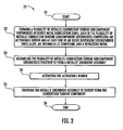
- Block 15 a plurality of metallic combustion turbine subcomponent greenbodies are assembled together to form a metallic greenbody assembly.
- the metallic greenbody assembly has a shape closely resembling that of the final combustion turbine component, but has a greater porosity, a lesser density, and a larger size.
- the plurality of metallic combustion turbine subcomponent greenbodies may be assembled by conventional methods known to those of skill in the art.
- a metallic combustion turbine subcomponent greenbody is an unsintered metallic combustion turbine subcomponent that lacks strength and has both a low density and high porosity compared to a sintered metallic body.
- the metallic greenbody assembly is sintered to thereby form the combustion turbine component.
- the metallic greenbody assembly may shrink in all directions by up to 20%, thereby increasing in density.
- the porosity of the metallic greenbody assembly is reduced and the strength of the metallic greenbody assembly is increased.
- the sintering may be solid state sintering or liquid state sintering.
- solid state sintering the metallic greenbody assembly is heated to a temperature below the melting point of its constituents and held at that temperature until its particles adhere to each other.
- liquid state sintering the metallic greenbody assembly is heated until at least one but not all of its constituents melt and reach a liquid state.
- the metallic greenbody assembly may be placed under pressure during the sintering.
- the sintering may comprise hot isostatic pressing (HIP).
- HIP subjects a component to high gas pressure in a containment vessel.
- the pressurizing gas is preferably argon, although other inert gasses may be used as will be appreciated by those of skill in the art.
- the pressurizing gas is preferably applied between 100 and 310 MPa (15,000 p.s.i. and 45,000 p.s.i.) at a temperature of 480°C to 2000°C, although other pressures and other temperatures may be used as well.
- the containment vessel is heated during the HIP, the pressure inside increases. The pressure is isostatic because it is applied to the metallic greenbody assembly from all directions evenly.
- the pressure and heat during HIP helps to reduce internal voids in the metallic greenbody assembly through a combination of plastic deformation, creep, and diffusion bonding, thus increasing the density of the metallic greenbody assembly.
- the sintering may be performed without the metallic greenbody assembly being placed under pressure. Block 18 indicates the end of the method.
- a bond coating may be formed on the combustion turbine component and a thermal barrier coating may be formed on the bond coating. Any number of exemplary bond coatings and thermal barrier coatings known to those of skill in the art may be used. In addition, the thermal barrier coating may be formed directly on the combustion turbine component, without an intervening bond coating. Additionally or alternatively, a wear resistant layer may be formed on the combustion turbine component.
- the combustion turbine component may be placed into a casting mold and that additional metallic layers may therefore be formed around the combustion turbine component, encasing it.
- a plurality of metallic combustion turbine subcomponent greenbodies may be assembled to form a metallic greenbody assembly and that the metallic greenbody assembly may be sintered to form a combustion turbine subcomponent assembly.
- Multiple combustion turbine subcomponent assemblies may be formed in this fashion and then joined together by conventional methods, such as welding or brazing, to form the combustion turbine component.
- the multiple combustion turbine subcomponent assemblies may also be placed into a casting mold and additional layers may be formed therearound to form a combustion turbine component
- Direct metal fabrication processes include (1) layered powder buildup processes, such as selective laser sintering (SLS), (2) processes using light energy to chemically change a material, such as stereolithography (SLA), (3) deposition techniques that selectively deposit either particles or thin laminates, such as solid ground curing (SGC), laminated object manufacturing (LOM), fused deposition modeling (FDM), and ballistic particle manufacturing (BPM), and (4) powder metallurgy processes that tightly compact a metal powder into a mold or die, such as metal injection molding (MIM) or tomo lithographic molding.
- SLS for example, uses a high powered laser to fuse the particles of a metal powder into a mass representing a desired three dimensional object, one layer at a time.
- the plurality of metallic combustion turbine subcomponent greenbodies may be formed by any of the above DMF processes, or by other processes known to those of skill in the art.
- each of the plurality of metallic combustion turbine subcomponent greenbodies may be formed by the same DMF process, or each may be formed by different DMF processes.
- Each of the plurality of metallic combustion turbine subcomponent greenbodies in this embodiment may comprise an activatable binder and at least one of an oxide dispersion strengthened (ODS) alloy, an intermetallic compound, and a refractory metal.
- ODS oxide dispersion strengthened
- Each of the plurality of metallic combustion turbine subcomponent greenbodies may also comprise a Nickel based superalloy and, optionally, at least one rare earth element.
- the activatable binder may comprise a polymer or plastic binder, a metallic mix including a melting point depressor, or another suitable binder known to those of skill in the art.
- Intermetallic compounds are solid phases containing two or more metallic elements, optionally having one or more non-metallic elements.
- Intermetallic phases form due to strong bonding between unlike metal atoms, this results in an ordered crystal structure, whereby the various atomic species occupy specific sublatice sites.
- Intermetallic compounds may also include interstitial compounds such as carbides and nitrides. Such intermetallic compounds offer advantageous properties like high temperature resistance and hardness.
- Refractory metals include tungsten, molybdenum, niobium, tantalum, and rhenium, and are extraordinarily resistant to heat and wear. The methods described herein allow the formation of combustion turbine components from the above materials, whereas conventional methods such as casting and forging may not. It should be noted that the plurality of metallic combustion turbine subcomponent greenbodies may be metallic and not contain any ceramic.
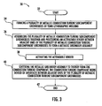
- the plurality of metallic combustion turbine subcomponent greenbodies are assembled together to form a metallic greenbody assembly.
- the activatable binder is activated.
- the activatable binder may be activated by heating the greenbody assembly, or may be activated by other suitable methods.
- the activatable binder may optionally be cured through the use of a chemical agent, ultraviolet radiation, bombardment with an electron beam, or further heating.
- the activatable binder may optionally be removed from the greenbody assembly by a pre-sintering heat treating at a temperature of 400°C to 600°C, or at other suitable temperatures, or through the use of chemical agents. This pre-sintering heat treating, in some embodiments, may increase the density, decrease the porosity, and shrink the greenbody assembly.
- Block 25 the metallic greenbody assembly is sintered to thereby form the combustion turbine component.
- Block 26 indicates the end of the method.
- a method of making a combustion turbine component which is an embodiment of the invention is now described.
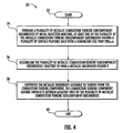
- a plurality of metallic combustion turbine subcomponent greenbodies is formed by tomo lithographic molding.
- Tomo lithographic molding involves the production of a master tool which is then used either directly as a mold or die, or alternatively used to produce a secondary consumable mold.
- To create the master tool a series of layers are fabricated with lithographic techniques. The layers are micro-machined to add additional features and details, and are then laminated together by brazing or epoxy bonding to form the master tool.
- the master tool may then be used as a mold or die for processes such as microcasting, microinjection molding, metal injection molding, and powder injection molding.
- tomo lithographic molding as used hereinafter is to mean the use of a master tool formed by tomo lithographic molding in conjunction with a suitable process to form metallic combustion turbine subcomponent greenbodies therefrom.
- the plurality of metallic combustion turbine subcomponent greenbodies is assembled together and an activatable binder is positioned between adjacent ones of the plurality of metallic combustion turbine subcomponent greenbodies to form a metallic greenbody assembly.
- the activatable binder is a metallic mix together with a melting point depressor.
- the activatable binder includes a melting point depressor.
- the sintering is liquid state sintering and the plurality of metallic combustion turbine subcomponent greenbodies are bonded together by transient liquid phase (TLP) bonding.
- the plurality of metallic combustion turbine subcomponent greenbodies is to be bonded together by TLP bonding.
- the activatable binder between each of the plurality of metallic combustion turbine subcomponent greenbodies is considered to be a TLP forming layer.
- the metallic greenbody assembly and thus the TLP forming layer are then heat treated at a temperature higher than the melting point of the TLP forming layer, but lower than the melting point of the other constituents of the metallic greenbody assembly. Accordingly, the TLP forming layer melts during the sintering.
- the melting point depressor diffuses from the TLP forming layer into each of the plurality of metallic combustion turbine subcomponent greenbodies, and molecules from each of the plurality of metallic combustion turbine subcomponent greenbodies diffuse into the TLP layer.
- the melting point of TLP layer increases beyond the temperature of the heat treatment and the TLP layer, now close in composition to the plurality of metallic combustion turbine subcomponent greenbodies, resolidifies.
- the resulting bonded region between each of the plurality of metallic combustion turbine subcomponent greenbodies is thin and of a high strength.
- the activatable binder may be positioned between certain adjacent ones of the plurality of metallic combustion turbine subcomponent greenbodies but not between other adjacent ones of the plurality of metallic combustion turbine subcomponent greenbodies.
- the activatable binder is activated.
- the metallic greenbody assembly is sintered to thereby form the combustion turbine component.
- the combustion turbine component is devoid of an interface between adjacent ones of the plurality of metallic combustion turbine subcomponent greenbodies after sintering. This lack of interfaces may provide the combustion turbine component with increased strength and the metallurgical properties throughout may be consistent.
- Block 42 indicates the end of the method.
- a plurality of metallic combustion turbine subcomponent greenbodies is formed by metal injection molding.
- Metal injection molding involves injecting a metallic powder and a suitable binder into a mold, in some situations with conventional plastic injection molding machines and processes.
- the mold used with the metal injection molding may be formed by tomo lithographic molding or may be formed from other methods.
- At least one of the plurality of metallic combustion turbine subcomponent greenbodies is formed to have at least one internal cooling passage.
- This internal cooling passage is formed to have a plurality of internal surface features, each with a dimension less than 200 ⁇ m. As will be explained in detail below, this plurality of internal surface features increases the internal surface area of the cooling passages of the combustion turbine component and therefore enhances its ability to transfer heat away from itself. As will also be explained in detail below, each of the plurality of internal surface features may take a variety of shapes and may be either a projection or a recess.
- one of the metallic combustion turbine subcomponent greenbodies need not have internal cooling passages.
- the surface features described herein may be external cooling features.
- the plurality of metallic combustion turbine subcomponent greenbodies is assembled together to form a metallic greenbody assembly.
- the metallic greenbody assembly is sintered to thereby form the combustion turbine component.
- the combustion turbine component has interfaces between adjacent ones of the plurality of metallic combustion turbine subcomponent greenbodies.
- Block 60 indicates the end of the method.
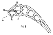
- the combustion turbine component 70 comprises a metallic body 71 to define at least a substrate for the combustion turbine component, the metallic body having a plurality of internal cooling passages 73.
- the internal cooling passages 73 each have an internal surface portion 75.
- the internal surface portion 75 defines a plurality of coarse surface cooling features 74, each having a dimension greater than 500 ⁇ m. As perhaps best shown in FIG. 6 , one of the plurality of coarse surface cooling features 74 illustratively comprises a three-tiered projection.
- a plurality of fine surface cooling features 76 is on at least one of plurality of coarse surface cooling features 74, each having a dimension less than 200 ⁇ m.
- the plurality of fine surface cooling features 76 illustratively comprises convex or hemispherical projections, and may be on the order of 50 ⁇ m, for example.
- the surface cooling features described herein increase the surface area of the internal surface portion 75 of the combustion turbine component 70, thereby enhancing its ability to transfer heat away from itself and cool itself and into a cooling fluid flowing therethrough. This enhanced heat transfer may allow for the size of the cooling passageways 73 to be decreased compared to those of conventional combustion turbine components. Furthermore, this enhanced heat transfer may allow for an amount of cooling fluid used to cool the combustion turbine component 70 to be reduced.
- a first additional surface cooling feature 77 comprising an "x" shaped projection is illustratively on the coarse surface cooling feature 74 and has a dimension greater than 200 ⁇ m. It should be understood that, although one first additional cooling feature 77 is shown, there may instead be a plurality of first additional surface cooling features on at least one of the plurality of coarse surface cooling features 74 and that ones of this plurality of first additional surface cooling features may be of sizes both greater than and less than 200 ⁇ m.
- a second additional surface cooling feature 78 comprising a circular-base pin and having a dimension less than 200 ⁇ m is illustratively on the first additional surface cooling feature 77.
- Each of the plurality of coarse surface cooling features 74, plurality of fine surface cooling features 76, first additional plurality of surface cooling features 77, and second additional plurality of surface cooling features 78 may be projections of other suitable shapes, including but not limited to square-base pins, circular-base pins, square-base pyramids, circular base cones, tapered pins, polygonal-based pyramids, conical frustums, pyramidical frustums, convex cones, serpentine ribs, hemispheres, and combinations thereof.
- Each of the plurality of coarse surface cooling features 74, plurality of fine surface cooling features 76, first additional plurality of surface cooling features 77, and second additional plurality of surface cooling features 78 may also be recesses of various shapes, including but not limited to concave cones, dimples, concave hemispheres, serpentine ribs, square shaped recesses, circular shaped pin recesses, and combinations thereof.
- Each of the plurality of coarse surface cooling features 74, plurality of fine surface cooling features 76, first additional plurality of surface cooling features 77, and second additional plurality of surface cooling features 78 may have the same shape, or each may have a different shape.
- one of the plurality of fine surface cooling features 76 may be a convex hemispherical projection while another of the plurality of fine surface cooling features may be a concave square shaped recess.
- the metallic combustion turbine component body 70 may comprise at least one of an oxide dispersion strengthened (ODS) alloy, an intermetallic compound, and a refractory metal. Advantages of construction from these materials are explained above.
- the metallic body 71 may comprise a plurality of metallic combustion turbine subcomponent bodies bonded together, or a plurality of metallic combustion turbine subcomponent greenbodies bonded together, by methods described in detail above.
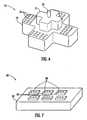
- One of a plurality of coarse surface cooling features 82 comprising a rectangular projection has a dimension greater than 500 ⁇ m, and a plurality of fine surface cooling features 86 comprising rectangular projections and having at least one dimension less than 200 ⁇ m is illustratively thereon.
- an internal surface portion of a cooling passage of an combustion turbine component 88 defines a plurality of coarse surface cooling features 90 comprising rectangular projections having a dimension, in this instance the width, that is greater than 500 ⁇ m.
- a plurality of fine surface cooling features 92 comprising hemispherical projections and having a dimension, in this instance a diameter, that is less than 200 ⁇ m is on the plurality of coarse surface cooling features 90.
- an internal surface portion of a cooling passage of a combustion turbine component 94 defines a plurality of coarse surface cooling features 96 comprising rectangular recesses having a dimension greater than 500 ⁇ m.
- a plurality of fine surface cooling features 98 comprising concave hemispherical recesses having a dimension less than 200 ⁇ m is defined in the plurality of coarse surface cooling features 98.
- FIG. 10 Illustrated in FIG. 10 is an internal surface portion of a cooling passage of an combustion turbine component 100 defining a plurality of coarse surface cooling features 102 comprising rectangular projections having a dimension greater than 500 ⁇ m.
- a plurality of fine surface cooling features 104 comprising concave hemispherical recesses having a dimension less than 200 ⁇ m is defined in the plurality of coarse surface cooling featu res 102.
- an internal surface portion of a cooling passage of a combustion turbine component 106 defines a plurality of coarse surface cooling features 108 comprising rectangular recesses having a dimension greater than 500 ⁇ m.
- a plurality of fine surface cooling features 110 comprising convex hemispheres and having a dimension less than 200 ⁇ m is on the plurality of coarse surface cooling features 108.
- the method includes forming a metallic combustion turbine component body by direct metal fabrication (DMF).
- the metallic combustion turbine component body is formed to have at least one surface portion defining a plurality of coarse surface cooling features each having a first dimension.
- the metallic combustion turbine component body is also formed to have at least one fine cooling feature on at least one of the first plurality of surface cooling features and having a second dimension less than 200 ⁇ m.
- the first dimension may be greater than 500 ⁇ m.
- the at least one fine surface cooling feature may comprise a projection or a convex projection.
- the at least one fine surface cooling feature may comprise a recess or a concave recess. If there are a plurality of fine surface cooling features, each of the plurality of fine surface cooling features may comprise the same shape, or may comprise different shapes (e.g. one of the plurality of fine surface cooling features may comprise a convex projection while another of the plurality of fine surface cooling features may comprise a concave recess).
- One of the plurality of coarse surface cooling features may comprise a projection or a convex projection.
- one of the plurality of coarse surface cooling features may comprise a recess or a concave recess.
- Each of the plurality of coarse cooling features may be the same shape or each may be a different shape.
- the DMF may comprise tomo lithographic molding or metal injection molding, details of which may also be found above.
- the metallic body may comprise at least one of an oxide dispersion strengthened (ODS) alloy, an intermetallic compound, and a refractory metal. Advantageous properties of these materials are discussed above.
- the metallic body may additionally or alternatively comprise a nickel based superalloy and, optionally, at least one rare earth element.
- a plurality of metallic combustion turbine subcomponent greenbodies are formed by direct metal fabrication (DMF). At least one of the plurality of metallic combustion turbine subcomponent greenbodies is formed to have at least one surface portion defining a plurality of coarse surface cooling features each having a first dimension. In addition, the at least one of the plurality of metallic combustion turbine subcomponent greenbodies is formed to have at least one fine surface cooling feature on at least one of the plurality of coarse surface cooling features and having a dimension less than the first dimension and less than 200 ⁇ m.
- DMF direct metal fabrication
- the plurality of metallic combustion turbine subcomponent greenbodies may comprise an activatable binder.
- the activatable binder may be activated prior to sintering.
- the plurality of metallic combustion turbine subcomponent greenbodies are assembled together to form a metallic greenbody assembly.
- the metallic greenbody assembly is sintered to thereby form the metallic body.
- Block 130 indicates the end of the method. Further details of assembling and sintering may be found above.
Landscapes
- Engineering & Computer Science (AREA)
- Manufacturing & Machinery (AREA)
- Mechanical Engineering (AREA)
- Chemical & Material Sciences (AREA)
- Composite Materials (AREA)
- Materials Engineering (AREA)
- Powder Metallurgy (AREA)
- Turbine Rotor Nozzle Sealing (AREA)
Claims (6)
- Procédé de fabrication d'un composant de turbine à combustion consistant :à réaliser chaque corps cru d'une pluralité de corps crus métalliques formant sous-composants de turbine à combustion par fabrication directe de pièces métalliques (DMF) ;à assembler la pluralité de corps crus métalliques formant sous-composants de turbine à combustion les uns avec les autres et à positionner un liant activable entre des corps crus adjacents parmi la pluralité de corps crus métalliques formant sous-composants de turbine à combustion pour réaliser un assemblage de corps crus métalliques, le liant activable comprenant un mélange métallique associé à un abaisseur de point de fusion ;à activer le liant activable pour exécuter une liaison en phase liquide transitoire (TLP) entre la pluralité de corps crus métalliques formant sous-composants de turbine à combustion de l'assemblage de corps crus métalliques, l'étape d'activation consistant à traiter à chaud l'assemblage de corps crus métalliques à une température supérieure au point de fusion du liant activable, mais inférieure au point de fusion de la pluralité de corps crus métalliques formant sous-composants de turbine à combustion, etaprès l'étape d'activation, à fritter à l'état liquide l'assemblage de corps crus métalliques comprenant le liant activable pour réaliser le composant de turbine à combustion.
- Procédé selon la revendication 1 dans lequel la DMF consiste en un moulage tomo-lithographique.
- Procédé selon la revendication 1 dans lequel la DMF consiste en un moulage par injection de métal.
- Procédé selon la revendication 1 dans lequel le composant de turbine à combustion est dépourvu d'interfaces entre les corps crus adjacents parmi la pluralité de corps crus métalliques formant sous-composants de turbine à combustion après frittage.
- Procédé selon la revendication 1 dans lequel chaque corps cru de la pluralité de corps crus métalliques formant sous-composants de turbine à combustion comprend au moins soit un alliage renforcé par dispersion d'oxydes (ODS), soit un composé intermétallique, soit un métal réfractaire.
- Procédé selon la revendication 1 dans lequel au moins un corps cru parmi la pluralité de corps crus métalliques formant sous-composants de turbine à combustion comporte une pluralité de détails superficiels ayant chacun une dimension inférieure à 200 µm.
Applications Claiming Priority (3)
| Application Number | Priority Date | Filing Date | Title |
|---|---|---|---|
| US2295208P | 2008-01-23 | 2008-01-23 | |
| US12/238,774 US20090183850A1 (en) | 2008-01-23 | 2008-09-26 | Method of Making a Combustion Turbine Component from Metallic Combustion Turbine Subcomponent Greenbodies |
| PCT/US2008/013454 WO2009094012A2 (fr) | 2008-01-23 | 2008-12-05 | Procédé de fabrication d'un composant de turbine à combustion à partir de corps crus métalliques de sous-composant de turbine à combustion |
Publications (2)
| Publication Number | Publication Date |
|---|---|
| EP2291254A2 EP2291254A2 (fr) | 2011-03-09 |
| EP2291254B1 true EP2291254B1 (fr) | 2014-02-12 |
Family
ID=40875513
Family Applications (1)
| Application Number | Title | Priority Date | Filing Date |
|---|---|---|---|
| EP08871459.7A Active EP2291254B1 (fr) | 2008-01-23 | 2008-12-05 | Procédé de fabrication d'un composant de turbine à combustion à partir de corps crus métalliques de sous-composant de turbine à combustion |
Country Status (3)
| Country | Link |
|---|---|
| US (2) | US20090183850A1 (fr) |
| EP (1) | EP2291254B1 (fr) |
| WO (1) | WO2009094012A2 (fr) |
Families Citing this family (61)
| Publication number | Priority date | Publication date | Assignee | Title |
|---|---|---|---|---|
| US20110204205A1 (en) * | 2010-02-25 | 2011-08-25 | Ahmed Kamel | Casting core for turbine engine components and method of making the same |
| US10081057B2 (en) | 2010-11-10 | 2018-09-25 | True Velocity, Inc. | Method of making a projectile by metal injection molding |
| US8561543B2 (en) | 2010-11-10 | 2013-10-22 | True Velocity, Inc. | Lightweight polymer ammunition cartridge casings |
| US11118875B1 (en) | 2010-11-10 | 2021-09-14 | True Velocity Ip Holdings, Llc | Color coded polymer ammunition cartridge |
| US10048052B2 (en) | 2010-11-10 | 2018-08-14 | True Velocity, Inc. | Method of making a polymeric subsonic ammunition cartridge |
| US10429156B2 (en) | 2010-11-10 | 2019-10-01 | True Velocity Ip Holdings, Llc | Subsonic polymeric ammunition cartridge |
| US10876822B2 (en) | 2017-11-09 | 2020-12-29 | True Velocity Ip Holdings, Llc | Multi-piece polymer ammunition cartridge |
| US9644930B1 (en) | 2010-11-10 | 2017-05-09 | True Velocity, Inc. | Method of making polymer ammunition having a primer diffuser |
| US10190857B2 (en) | 2010-11-10 | 2019-01-29 | True Velocity Ip Holdings, Llc | Method of making polymeric subsonic ammunition |
| US11340050B2 (en) | 2010-11-10 | 2022-05-24 | True Velocity Ip Holdings, Llc | Subsonic polymeric ammunition cartridge |
| US10480915B2 (en) | 2010-11-10 | 2019-11-19 | True Velocity Ip Holdings, Llc | Method of making a polymeric subsonic ammunition cartridge |
| US10048049B2 (en) | 2010-11-10 | 2018-08-14 | True Velocity, Inc. | Lightweight polymer ammunition cartridge having a primer diffuser |
| US10591260B2 (en) | 2010-11-10 | 2020-03-17 | True Velocity Ip Holdings, Llc | Polymer ammunition having a projectile made by metal injection molding |
| US9885551B2 (en) | 2010-11-10 | 2018-02-06 | True Velocity, Inc. | Subsonic polymeric ammunition |
| US10352670B2 (en) * | 2010-11-10 | 2019-07-16 | True Velocity Ip Holdings, Llc | Lightweight polymer ammunition cartridge casings |
| US10041770B2 (en) | 2010-11-10 | 2018-08-07 | True Velocity, Inc. | Metal injection molded ammunition cartridge |
| US8999226B2 (en) | 2011-08-30 | 2015-04-07 | Siemens Energy, Inc. | Method of forming a thermal barrier coating system with engineered surface roughness |
| CH705662A1 (de) * | 2011-11-04 | 2013-05-15 | Alstom Technology Ltd | Prozess zur Herstellung von Gegenständen aus einer durch Gamma-Prime-Ausscheidung verfestigten Superlegierung auf Nickelbasis durch selektives Laserschmelzen (SLM). |
| USD861118S1 (en) * | 2011-11-09 | 2019-09-24 | True Velocity Ip Holdings, Llc | Primer insert |
| US9243502B2 (en) * | 2012-04-24 | 2016-01-26 | United Technologies Corporation | Airfoil cooling enhancement and method of making the same |
| US20140003923A1 (en) | 2012-07-02 | 2014-01-02 | Peter Finnigan | Functionally graded composite fan containment case |
| EP2900964A4 (fr) * | 2012-09-28 | 2016-06-29 | United Technologies Corp | Composant de section de turbine surrefroidie fabriqué par fabrication additive |
| US9700941B2 (en) | 2012-10-03 | 2017-07-11 | Siemens Energy, Inc. | Method for repairing a component for use in a turbine engine |
| ES2777927T3 (es) * | 2012-10-12 | 2020-08-06 | MTU Aero Engines AG | Componente para una turbina |
| US9393620B2 (en) | 2012-12-14 | 2016-07-19 | United Technologies Corporation | Uber-cooled turbine section component made by additive manufacturing |
| BR112015025346A2 (pt) | 2013-04-05 | 2017-07-18 | Federal Mogul Corp | pistão produzido através do uso de técnicas de fabricação de aditivos |
| CN105339942B (zh) * | 2013-06-28 | 2020-04-07 | 联合工艺公司 | 添加制造系统和制造方法 |
| EP3036055B1 (fr) * | 2013-08-23 | 2019-07-03 | Siemens Energy, Inc. | Noyau de coulée de composant de turbine doté d'une région haute résolution |
| DE102013224319A1 (de) * | 2013-11-27 | 2015-06-11 | Eos Gmbh Electro Optical Systems | Verfahren und Vorrichtung zum generativen Herstellen zumindest eines Bauteilbereichs eines Bauteils |
| EP3148730A1 (fr) * | 2014-05-29 | 2017-04-05 | The Exone Company | Procédé permettant de fabriquer des articles en superalliage à base de nickel au moyen d'une impression en trois dimensions |
| JP6470135B2 (ja) | 2014-07-14 | 2019-02-13 | ユナイテッド テクノロジーズ コーポレイションUnited Technologies Corporation | 付加製造された表面仕上げ |
| WO2016012399A1 (fr) * | 2014-07-21 | 2016-01-28 | Nuovo Pignone Srl | Procédé de fabrication de composants de machine par fabrication additive |
| DE102014226370A1 (de) * | 2014-12-18 | 2016-06-23 | Siemens Aktiengesellschaft | Verfahren zur generativen Fertigung eines Werkstücksaus einem Rohmaterial |
| US10094240B2 (en) | 2015-02-12 | 2018-10-09 | United Technologies Corporation | Anti-deflection feature for additively manufactured thin metal parts and method of additively manufacturing thin metal parts |
| US10156157B2 (en) * | 2015-02-13 | 2018-12-18 | United Technologies Corporation | S-shaped trip strips in internally cooled components |
| FR3036300B1 (fr) * | 2015-05-21 | 2017-06-23 | Snecma | Procede de fabrication d'une piece avec surface d'assemblage par fabrication additive |
| US9751792B2 (en) | 2015-08-12 | 2017-09-05 | Johns Manville | Post-manufacturing processes for submerged combustion burner |
| US9587918B1 (en) | 2015-09-24 | 2017-03-07 | True Velocity, Inc. | Ammunition having a projectile made by metal injection molding |
| US9523563B1 (en) | 2016-03-09 | 2016-12-20 | True Velocity, Inc. | Method of making ammunition having a two-piece primer insert |
| US9869536B2 (en) | 2016-03-09 | 2018-01-16 | True Velocity, Inc. | Method of making a two-piece primer insert |
| US9518810B1 (en) | 2016-03-09 | 2016-12-13 | True Velocity, Inc. | Polymer ammunition cartridge having a two-piece primer insert |
| US9551557B1 (en) | 2016-03-09 | 2017-01-24 | True Velocity, Inc. | Polymer ammunition having a two-piece primer insert |
| US9506735B1 (en) | 2016-03-09 | 2016-11-29 | True Velocity, Inc. | Method of making polymer ammunition cartridges having a two-piece primer insert |
| US9835427B2 (en) | 2016-03-09 | 2017-12-05 | True Velocity, Inc. | Two-piece primer insert for polymer ammunition |
| US10556269B1 (en) | 2017-03-29 | 2020-02-11 | United Technologies Corporation | Apparatus for and method of making multi-walled passages in components |
| US10596621B1 (en) | 2017-03-29 | 2020-03-24 | United Technologies Corporation | Method of making complex internal passages in turbine airfoils |
| US10760882B1 (en) | 2017-08-08 | 2020-09-01 | True Velocity Ip Holdings, Llc | Metal injection molded ammunition cartridge |
| EP3569330A1 (fr) | 2018-05-15 | 2019-11-20 | Rolls-Royce Corporation | Composants d'alliage fabriqués de manière additive |
| US11739691B2 (en) * | 2018-06-28 | 2023-08-29 | Raytheon Technologies Corporation | Engine component |
| US11313243B2 (en) | 2018-07-12 | 2022-04-26 | Rolls-Royce North American Technologies, Inc. | Non-continuous abradable coatings |
| FR3094032B1 (fr) * | 2019-03-22 | 2021-05-21 | Safran Aircraft Engines | Aube de turbomachine d’aeronef et son procede de fabrication par moulage a cire perdue |
| FR3099717B1 (fr) * | 2019-08-06 | 2022-06-10 | Safran Aircraft Engines | Procédé de fabrication d’une pièce métallique |
| US12459196B2 (en) | 2019-11-14 | 2025-11-04 | Rolls-Royce Corporation | Patterned filament for fused filament fabrication |
| EP3822004A1 (fr) | 2019-11-14 | 2021-05-19 | Rolls-Royce Corporation | Fabrication de filaments fusionnés de revêtements abrasibles |
| US12146419B1 (en) | 2020-01-07 | 2024-11-19 | Rtx Corporation | Multi-alloy turbine engine components and manufacture methods |
| US12173615B2 (en) | 2020-02-14 | 2024-12-24 | Rtx Corporation | Multi-zone blade fabrication |
| EP4105438B1 (fr) | 2021-06-18 | 2026-04-08 | RTX Corporation | Méthode de collage pour la réparation d'une pièce d'un moteur à turbine à gaz |
| EP4105449A1 (fr) | 2021-06-18 | 2022-12-21 | Raytheon Technologies Corporation | Configuration hybride collée pour le joint d'air extérieur d'une aube (boas) |
| EP4105450A1 (fr) | 2021-06-18 | 2022-12-21 | Raytheon Technologies Corporation | Système de contrôle de jeu passif produite par une technologie par frittage assisté par champ électrique (fast) |
| US12055056B2 (en) | 2021-06-18 | 2024-08-06 | Rtx Corporation | Hybrid superalloy article and method of manufacture thereof |
| GB2608193A (en) * | 2021-06-25 | 2022-12-28 | Qdot Tech Ltd | Co-sintering |
Family Cites Families (27)
| Publication number | Priority date | Publication date | Assignee | Title |
|---|---|---|---|---|
| US3678570A (en) * | 1971-04-01 | 1972-07-25 | United Aircraft Corp | Diffusion bonding utilizing transient liquid phase |
| US4766420A (en) * | 1978-06-05 | 1988-08-23 | Hastings Otis | Insulating apparatus and composite laminates employed therein |
| GB2198433B (en) * | 1986-12-05 | 1990-11-07 | Romain Louis Billiet | Improvements in or relating to the removal of organic binding agents from articles moulded from sinterable materials |
| US5419971A (en) * | 1993-03-03 | 1995-05-30 | General Electric Company | Enhanced thermal barrier coating system |
| US5681661A (en) * | 1996-02-09 | 1997-10-28 | Board Of Supervisors Of Louisiana State University And Agricultural And Mechanical College | High aspect ratio, microstructure-covered, macroscopic surfaces |
| US5880382A (en) * | 1996-08-01 | 1999-03-09 | Smith International, Inc. | Double cemented carbide composites |
| US6033788A (en) * | 1996-11-15 | 2000-03-07 | Case Western Reserve University | Process for joining powder metallurgy objects in the green (or brown) state |
| US5932055A (en) * | 1997-11-11 | 1999-08-03 | Rockwell Science Center Llc | Direct metal fabrication (DMF) using a carbon precursor to bind the "green form" part and catalyze a eutectic reducing element in a supersolidus liquid phase sintering (SLPS) process |
| FR2785559B1 (fr) * | 1998-11-10 | 2001-03-02 | Metals Process Systems | Procede de fabrication par metallurgie des poudres de pieces de forme autobrasantes |
| US20040124231A1 (en) * | 1999-06-29 | 2004-07-01 | Hasz Wayne Charles | Method for coating a substrate |
| US6517773B1 (en) * | 1999-09-23 | 2003-02-11 | Innovative Technology Licensing, Llc | Direct metal fabrication of parts with surface features only |
| US6502624B1 (en) * | 2000-04-18 | 2003-01-07 | Williams International Co., L.L.C. | Multiproperty metal forming process |
| US20020085941A1 (en) * | 2000-12-29 | 2002-07-04 | Deevi Seetharama C. | Processing of aluminides by sintering of intermetallic powders |
| US6434946B1 (en) * | 2001-04-06 | 2002-08-20 | General Electric Company | Method for making an article assembly with a brazed joint and brazed assembly and preform |
| US7785098B1 (en) * | 2001-06-05 | 2010-08-31 | Mikro Systems, Inc. | Systems for large area micro mechanical systems |
| US20030101891A1 (en) * | 2001-12-05 | 2003-06-05 | Amick Darryl D. | Jacketed bullet and methods of making the same |
| US9068464B2 (en) * | 2002-09-17 | 2015-06-30 | Siemens Energy, Inc. | Method of joining ceramic parts and articles so formed |
| US7032800B2 (en) * | 2003-05-30 | 2006-04-25 | General Electric Company | Apparatus and method for friction stir welding of high strength materials, and articles made therefrom |
| US7241416B2 (en) * | 2003-08-12 | 2007-07-10 | Borg Warner Inc. | Metal injection molded turbine rotor and metal injection molded shaft connection attachment thereto |
| US7052241B2 (en) * | 2003-08-12 | 2006-05-30 | Borgwarner Inc. | Metal injection molded turbine rotor and metal shaft connection attachment thereto |
| US7237730B2 (en) * | 2005-03-17 | 2007-07-03 | Pratt & Whitney Canada Corp. | Modular fuel nozzle and method of making |
| US7721436B2 (en) * | 2005-12-20 | 2010-05-25 | Pratt & Whitney Canada Corp. | Method of manufacturing a metal injection moulded combustor swirler |
| US7658315B2 (en) * | 2006-01-09 | 2010-02-09 | General Electric Company | Process of brazing superalloy components |
| US20070295785A1 (en) * | 2006-05-31 | 2007-12-27 | General Electric Company | Microwave brazing using mim preforms |
| US20080000611A1 (en) * | 2006-06-28 | 2008-01-03 | Ronald Scott Bunker | Method for Forming Casting Molds |
| US7966820B2 (en) * | 2007-08-15 | 2011-06-28 | General Electric Company | Method and apparatus for combusting fuel within a gas turbine engine |
| US8096751B2 (en) * | 2008-07-31 | 2012-01-17 | Siemens Energy, Inc. | Turbine engine component with cooling passages |
-
2008
- 2008-09-26 US US12/238,774 patent/US20090183850A1/en not_active Abandoned
- 2008-12-05 EP EP08871459.7A patent/EP2291254B1/fr active Active
- 2008-12-05 WO PCT/US2008/013454 patent/WO2009094012A2/fr not_active Ceased
-
2013
- 2013-12-30 US US14/142,993 patent/US20140294652A1/en not_active Abandoned
Also Published As
| Publication number | Publication date |
|---|---|
| US20140294652A1 (en) | 2014-10-02 |
| WO2009094012A2 (fr) | 2009-07-30 |
| US20090183850A1 (en) | 2009-07-23 |
| EP2291254A2 (fr) | 2011-03-09 |
| WO2009094012A3 (fr) | 2011-06-30 |
Similar Documents
| Publication | Publication Date | Title |
|---|---|---|
| EP2291254B1 (fr) | Procédé de fabrication d'un composant de turbine à combustion à partir de corps crus métalliques de sous-composant de turbine à combustion | |
| US20110016717A1 (en) | Method of Making a Combustion Turbine Component Having a Plurality of Surface Cooling Features and Associated Components | |
| JP5318372B2 (ja) | 金属複合材発泡体構成部品を製造する方法及び金属複合材構成部品のためのプリフォーム | |
| JP7532496B2 (ja) | 高温ガスタービン・ブレードを修復するためのシステム及び方法 | |
| US6384365B1 (en) | Repair and fabrication of combustion turbine components by spark plasma sintering | |
| US8956478B2 (en) | Process for joining refractory ceramic parts by spark plasma sintering (SPS) | |
| CN105710377B (zh) | 使用用于复合部件的复合增材制造特征的复合增材制造方法 | |
| US11448230B2 (en) | Method for manufacturing a turbomachine component | |
| CA2776075C (fr) | Segment d'enveloppe de turbine avec plateau de contact integre | |
| US9221101B2 (en) | Process for local repair of a damaged thermomechanical part and part thus produced, in particular a turbine part | |
| US12065949B2 (en) | System and method for repairing high-temperature gas turbine components | |
| US20130086785A1 (en) | Hybrid repair plugs and repair methods incorporating the same | |
| TW200524692A (en) | Method for repairing machine part, method for forming restored machine part, method for manufacturing machine part, gas turbine engine, electric discharge machine, method for repairing turbine component, and method for forming restored turbine component | |
| JP2022544565A (ja) | 付加製造された押出機構成要素 | |
| JPS6049586B2 (ja) | 熱機関のブレ−ドおよびその製法 | |
| EP3128129A1 (fr) | Aubes de compresseur métalliques hybrides | |
| JP2016013575A (ja) | 繊維強化ろう付け部品及びその方法 | |
| JP6918507B2 (ja) | 熱間等方圧加圧法により第1の金属部品の周囲に形成された第2の金属部品を用いた鋳造 | |
| EP1527842A1 (fr) | Procédé de fabrication d'un article composite métallique renforcé par de fibres | |
| WO2009001026A1 (fr) | Procédé d'assemblage et de réparation | |
| EP3187284B1 (fr) | Liaison dynamique des matériaux de la métallurgie des poudres |
Legal Events
| Date | Code | Title | Description |
|---|---|---|---|
| PUAI | Public reference made under article 153(3) epc to a published international application that has entered the european phase |
Free format text: ORIGINAL CODE: 0009012 |
|
| 17P | Request for examination filed |
Effective date: 20100507 |
|
| AK | Designated contracting states |
Kind code of ref document: A2 Designated state(s): AT BE BG CH CY CZ DE DK EE ES FI FR GB GR HR HU IE IS IT LI LT LU LV MC MT NL NO PL PT RO SE SI SK TR |
|
| AX | Request for extension of the european patent |
Extension state: AL BA MK RS |
|
| RIN1 | Information on inventor provided before grant (corrected) |
Inventor name: MORRISON, JAY, A. Inventor name: LANE, JAY, E. Inventor name: JAMES, ALLISTER, W. |
|
| DAX | Request for extension of the european patent (deleted) | ||
| RAP1 | Party data changed (applicant data changed or rights of an application transferred) |
Owner name: MIKRO SYSTEMS INC. Owner name: SIEMENS ENERGY, INC. |
|
| 17Q | First examination report despatched |
Effective date: 20121017 |
|
| GRAP | Despatch of communication of intention to grant a patent |
Free format text: ORIGINAL CODE: EPIDOSNIGR1 |
|
| INTG | Intention to grant announced |
Effective date: 20130712 |
|
| GRAS | Grant fee paid |
Free format text: ORIGINAL CODE: EPIDOSNIGR3 |
|
| GRAA | (expected) grant |
Free format text: ORIGINAL CODE: 0009210 |
|
| AK | Designated contracting states |
Kind code of ref document: B1 Designated state(s): AT BE BG CH CY CZ DE DK EE ES FI FR GB GR HR HU IE IS IT LI LT LU LV MC MT NL NO PL PT RO SE SI SK TR |
|
| REG | Reference to a national code |
Ref country code: GB Ref legal event code: FG4D |
|
| REG | Reference to a national code |
Ref country code: CH Ref legal event code: EP |
|
| REG | Reference to a national code |
Ref country code: AT Ref legal event code: REF Ref document number: 651904 Country of ref document: AT Kind code of ref document: T Effective date: 20140215 |
|
| RIN2 | Information on inventor provided after grant (corrected) |
Inventor name: MORRISON, JAY, A. Inventor name: LANE, JAY, E. Inventor name: JAMES, ALLISTER, WILLIAM |
|
| REG | Reference to a national code |
Ref country code: IE Ref legal event code: FG4D |
|
| REG | Reference to a national code |
Ref country code: DE Ref legal event code: R096 Ref document number: 602008030314 Country of ref document: DE Effective date: 20140327 |
|
| REG | Reference to a national code |
Ref country code: DE Ref legal event code: R083 Ref document number: 602008030314 Country of ref document: DE |
|
| RAP2 | Party data changed (patent owner data changed or rights of a patent transferred) |
Owner name: SIEMENS ENERGY, INC. Owner name: MIKRO SYSTEMS INC. |
|
| REG | Reference to a national code |
Ref country code: FR Ref legal event code: CA Effective date: 20140414 |
|
| REG | Reference to a national code |
Ref country code: NL Ref legal event code: VDEP Effective date: 20140212 |
|
| REG | Reference to a national code |
Ref country code: AT Ref legal event code: MK05 Ref document number: 651904 Country of ref document: AT Kind code of ref document: T Effective date: 20140212 |
|
| REG | Reference to a national code |
Ref country code: LT Ref legal event code: MG4D |
|
| PG25 | Lapsed in a contracting state [announced via postgrant information from national office to epo] |
Ref country code: IS Free format text: LAPSE BECAUSE OF FAILURE TO SUBMIT A TRANSLATION OF THE DESCRIPTION OR TO PAY THE FEE WITHIN THE PRESCRIBED TIME-LIMIT Effective date: 20140612 Ref country code: LT Free format text: LAPSE BECAUSE OF FAILURE TO SUBMIT A TRANSLATION OF THE DESCRIPTION OR TO PAY THE FEE WITHIN THE PRESCRIBED TIME-LIMIT Effective date: 20140212 Ref country code: NO Free format text: LAPSE BECAUSE OF FAILURE TO SUBMIT A TRANSLATION OF THE DESCRIPTION OR TO PAY THE FEE WITHIN THE PRESCRIBED TIME-LIMIT Effective date: 20140512 |
|
| PG25 | Lapsed in a contracting state [announced via postgrant information from national office to epo] |
Ref country code: FI Free format text: LAPSE BECAUSE OF FAILURE TO SUBMIT A TRANSLATION OF THE DESCRIPTION OR TO PAY THE FEE WITHIN THE PRESCRIBED TIME-LIMIT Effective date: 20140212 Ref country code: NL Free format text: LAPSE BECAUSE OF FAILURE TO SUBMIT A TRANSLATION OF THE DESCRIPTION OR TO PAY THE FEE WITHIN THE PRESCRIBED TIME-LIMIT Effective date: 20140212 Ref country code: CY Free format text: LAPSE BECAUSE OF FAILURE TO SUBMIT A TRANSLATION OF THE DESCRIPTION OR TO PAY THE FEE WITHIN THE PRESCRIBED TIME-LIMIT Effective date: 20140212 Ref country code: ES Free format text: LAPSE BECAUSE OF FAILURE TO SUBMIT A TRANSLATION OF THE DESCRIPTION OR TO PAY THE FEE WITHIN THE PRESCRIBED TIME-LIMIT Effective date: 20140212 Ref country code: PT Free format text: LAPSE BECAUSE OF FAILURE TO SUBMIT A TRANSLATION OF THE DESCRIPTION OR TO PAY THE FEE WITHIN THE PRESCRIBED TIME-LIMIT Effective date: 20140612 Ref country code: SE Free format text: LAPSE BECAUSE OF FAILURE TO SUBMIT A TRANSLATION OF THE DESCRIPTION OR TO PAY THE FEE WITHIN THE PRESCRIBED TIME-LIMIT Effective date: 20140212 Ref country code: AT Free format text: LAPSE BECAUSE OF FAILURE TO SUBMIT A TRANSLATION OF THE DESCRIPTION OR TO PAY THE FEE WITHIN THE PRESCRIBED TIME-LIMIT Effective date: 20140212 |
|
| PG25 | Lapsed in a contracting state [announced via postgrant information from national office to epo] |
Ref country code: BE Free format text: LAPSE BECAUSE OF FAILURE TO SUBMIT A TRANSLATION OF THE DESCRIPTION OR TO PAY THE FEE WITHIN THE PRESCRIBED TIME-LIMIT Effective date: 20140212 Ref country code: LV Free format text: LAPSE BECAUSE OF FAILURE TO SUBMIT A TRANSLATION OF THE DESCRIPTION OR TO PAY THE FEE WITHIN THE PRESCRIBED TIME-LIMIT Effective date: 20140212 Ref country code: HR Free format text: LAPSE BECAUSE OF FAILURE TO SUBMIT A TRANSLATION OF THE DESCRIPTION OR TO PAY THE FEE WITHIN THE PRESCRIBED TIME-LIMIT Effective date: 20140212 |
|
| PG25 | Lapsed in a contracting state [announced via postgrant information from national office to epo] |
Ref country code: RO Free format text: LAPSE BECAUSE OF FAILURE TO SUBMIT A TRANSLATION OF THE DESCRIPTION OR TO PAY THE FEE WITHIN THE PRESCRIBED TIME-LIMIT Effective date: 20140212 Ref country code: CZ Free format text: LAPSE BECAUSE OF FAILURE TO SUBMIT A TRANSLATION OF THE DESCRIPTION OR TO PAY THE FEE WITHIN THE PRESCRIBED TIME-LIMIT Effective date: 20140212 Ref country code: EE Free format text: LAPSE BECAUSE OF FAILURE TO SUBMIT A TRANSLATION OF THE DESCRIPTION OR TO PAY THE FEE WITHIN THE PRESCRIBED TIME-LIMIT Effective date: 20140212 Ref country code: DK Free format text: LAPSE BECAUSE OF FAILURE TO SUBMIT A TRANSLATION OF THE DESCRIPTION OR TO PAY THE FEE WITHIN THE PRESCRIBED TIME-LIMIT Effective date: 20140212 |
|
| REG | Reference to a national code |
Ref country code: DE Ref legal event code: R097 Ref document number: 602008030314 Country of ref document: DE |
|
| PG25 | Lapsed in a contracting state [announced via postgrant information from national office to epo] |
Ref country code: SK Free format text: LAPSE BECAUSE OF FAILURE TO SUBMIT A TRANSLATION OF THE DESCRIPTION OR TO PAY THE FEE WITHIN THE PRESCRIBED TIME-LIMIT Effective date: 20140212 Ref country code: PL Free format text: LAPSE BECAUSE OF FAILURE TO SUBMIT A TRANSLATION OF THE DESCRIPTION OR TO PAY THE FEE WITHIN THE PRESCRIBED TIME-LIMIT Effective date: 20140212 |
|
| PLBE | No opposition filed within time limit |
Free format text: ORIGINAL CODE: 0009261 |
|
| STAA | Information on the status of an ep patent application or granted ep patent |
Free format text: STATUS: NO OPPOSITION FILED WITHIN TIME LIMIT |
|
| 26N | No opposition filed |
Effective date: 20141113 |
|
| REG | Reference to a national code |
Ref country code: DE Ref legal event code: R097 Ref document number: 602008030314 Country of ref document: DE Effective date: 20141113 |
|
| PG25 | Lapsed in a contracting state [announced via postgrant information from national office to epo] |
Ref country code: SI Free format text: LAPSE BECAUSE OF FAILURE TO SUBMIT A TRANSLATION OF THE DESCRIPTION OR TO PAY THE FEE WITHIN THE PRESCRIBED TIME-LIMIT Effective date: 20140212 |
|
| PG25 | Lapsed in a contracting state [announced via postgrant information from national office to epo] |
Ref country code: LU Free format text: LAPSE BECAUSE OF FAILURE TO SUBMIT A TRANSLATION OF THE DESCRIPTION OR TO PAY THE FEE WITHIN THE PRESCRIBED TIME-LIMIT Effective date: 20141205 |
|
| REG | Reference to a national code |
Ref country code: CH Ref legal event code: PL |
|
| REG | Reference to a national code |
Ref country code: IE Ref legal event code: MM4A |
|
| PG25 | Lapsed in a contracting state [announced via postgrant information from national office to epo] |
Ref country code: CH Free format text: LAPSE BECAUSE OF NON-PAYMENT OF DUE FEES Effective date: 20141231 Ref country code: LI Free format text: LAPSE BECAUSE OF NON-PAYMENT OF DUE FEES Effective date: 20141231 Ref country code: IE Free format text: LAPSE BECAUSE OF NON-PAYMENT OF DUE FEES Effective date: 20141205 |
|
| REG | Reference to a national code |
Ref country code: FR Ref legal event code: PLFP Year of fee payment: 8 |
|
| PG25 | Lapsed in a contracting state [announced via postgrant information from national office to epo] |
Ref country code: MC Free format text: LAPSE BECAUSE OF FAILURE TO SUBMIT A TRANSLATION OF THE DESCRIPTION OR TO PAY THE FEE WITHIN THE PRESCRIBED TIME-LIMIT Effective date: 20140212 Ref country code: BG Free format text: LAPSE BECAUSE OF FAILURE TO SUBMIT A TRANSLATION OF THE DESCRIPTION OR TO PAY THE FEE WITHIN THE PRESCRIBED TIME-LIMIT Effective date: 20140212 |
|
| PG25 | Lapsed in a contracting state [announced via postgrant information from national office to epo] |
Ref country code: GR Free format text: LAPSE BECAUSE OF FAILURE TO SUBMIT A TRANSLATION OF THE DESCRIPTION OR TO PAY THE FEE WITHIN THE PRESCRIBED TIME-LIMIT Effective date: 20140513 |
|
| PG25 | Lapsed in a contracting state [announced via postgrant information from national office to epo] |
Ref country code: HU Free format text: LAPSE BECAUSE OF FAILURE TO SUBMIT A TRANSLATION OF THE DESCRIPTION OR TO PAY THE FEE WITHIN THE PRESCRIBED TIME-LIMIT; INVALID AB INITIO Effective date: 20081205 Ref country code: MT Free format text: LAPSE BECAUSE OF FAILURE TO SUBMIT A TRANSLATION OF THE DESCRIPTION OR TO PAY THE FEE WITHIN THE PRESCRIBED TIME-LIMIT Effective date: 20140212 Ref country code: TR Free format text: LAPSE BECAUSE OF FAILURE TO SUBMIT A TRANSLATION OF THE DESCRIPTION OR TO PAY THE FEE WITHIN THE PRESCRIBED TIME-LIMIT Effective date: 20140212 |
|
| REG | Reference to a national code |
Ref country code: FR Ref legal event code: PLFP Year of fee payment: 9 |
|
| REG | Reference to a national code |
Ref country code: FR Ref legal event code: PLFP Year of fee payment: 10 |
|
| PGFP | Annual fee paid to national office [announced via postgrant information from national office to epo] |
Ref country code: GB Payment date: 20251223 Year of fee payment: 18 |
|
| PGFP | Annual fee paid to national office [announced via postgrant information from national office to epo] |
Ref country code: IT Payment date: 20251218 Year of fee payment: 18 |
|
| PGFP | Annual fee paid to national office [announced via postgrant information from national office to epo] |
Ref country code: FR Payment date: 20251119 Year of fee payment: 18 |
|
| P01 | Opt-out of the competence of the unified patent court (upc) registered |
Free format text: CASE NUMBER: UPC_APP_0019524_2291254/2025 Effective date: 20251228 |
|
| PGFP | Annual fee paid to national office [announced via postgrant information from national office to epo] |
Ref country code: DE Payment date: 20251229 Year of fee payment: 18 |