EP2291271B1 - Procédé d'extrusion de matières plastiques - Google Patents
Procédé d'extrusion de matières plastiques Download PDFInfo
- Publication number
- EP2291271B1 EP2291271B1 EP09765580.7A EP09765580A EP2291271B1 EP 2291271 B1 EP2291271 B1 EP 2291271B1 EP 09765580 A EP09765580 A EP 09765580A EP 2291271 B1 EP2291271 B1 EP 2291271B1
- Authority
- EP
- European Patent Office
- Prior art keywords
- screw
- profile
- screw profile
- point
- circular arcs
- Prior art date
- Legal status (The legal status is an assumption and is not a legal conclusion. Google has not performed a legal analysis and makes no representation as to the accuracy of the status listed.)
- Not-in-force
Links
Images







Classifications
-
- B—PERFORMING OPERATIONS; TRANSPORTING
- B29—WORKING OF PLASTICS; WORKING OF SUBSTANCES IN A PLASTIC STATE IN GENERAL
- B29B—PREPARATION OR PRETREATMENT OF THE MATERIAL TO BE SHAPED; MAKING GRANULES OR PREFORMS; RECOVERY OF PLASTICS OR OTHER CONSTITUENTS OF WASTE MATERIAL CONTAINING PLASTICS
- B29B7/00—Mixing; Kneading
- B29B7/30—Mixing; Kneading continuous, with mechanical mixing or kneading devices
- B29B7/34—Mixing; Kneading continuous, with mechanical mixing or kneading devices with movable mixing or kneading devices
- B29B7/38—Mixing; Kneading continuous, with mechanical mixing or kneading devices with movable mixing or kneading devices rotary
- B29B7/46—Mixing; Kneading continuous, with mechanical mixing or kneading devices with movable mixing or kneading devices rotary with more than one shaft
- B29B7/48—Mixing; Kneading continuous, with mechanical mixing or kneading devices with movable mixing or kneading devices rotary with more than one shaft with intermeshing devices, e.g. screws
- B29B7/481—Mixing; Kneading continuous, with mechanical mixing or kneading devices with movable mixing or kneading devices rotary with more than one shaft with intermeshing devices, e.g. screws provided with paddles, gears or discs
-
- B—PERFORMING OPERATIONS; TRANSPORTING
- B29—WORKING OF PLASTICS; WORKING OF SUBSTANCES IN A PLASTIC STATE IN GENERAL
- B29B—PREPARATION OR PRETREATMENT OF THE MATERIAL TO BE SHAPED; MAKING GRANULES OR PREFORMS; RECOVERY OF PLASTICS OR OTHER CONSTITUENTS OF WASTE MATERIAL CONTAINING PLASTICS
- B29B7/00—Mixing; Kneading
- B29B7/30—Mixing; Kneading continuous, with mechanical mixing or kneading devices
- B29B7/34—Mixing; Kneading continuous, with mechanical mixing or kneading devices with movable mixing or kneading devices
- B29B7/38—Mixing; Kneading continuous, with mechanical mixing or kneading devices with movable mixing or kneading devices rotary
- B29B7/46—Mixing; Kneading continuous, with mechanical mixing or kneading devices with movable mixing or kneading devices rotary with more than one shaft
- B29B7/48—Mixing; Kneading continuous, with mechanical mixing or kneading devices with movable mixing or kneading devices rotary with more than one shaft with intermeshing devices, e.g. screws
- B29B7/482—Mixing; Kneading continuous, with mechanical mixing or kneading devices with movable mixing or kneading devices rotary with more than one shaft with intermeshing devices, e.g. screws provided with screw parts in addition to other mixing parts, e.g. paddles, gears, discs
- B29B7/483—Mixing; Kneading continuous, with mechanical mixing or kneading devices with movable mixing or kneading devices rotary with more than one shaft with intermeshing devices, e.g. screws provided with screw parts in addition to other mixing parts, e.g. paddles, gears, discs the other mixing parts being discs perpendicular to the screw axis
-
- B—PERFORMING OPERATIONS; TRANSPORTING
- B29—WORKING OF PLASTICS; WORKING OF SUBSTANCES IN A PLASTIC STATE IN GENERAL
- B29B—PREPARATION OR PRETREATMENT OF THE MATERIAL TO BE SHAPED; MAKING GRANULES OR PREFORMS; RECOVERY OF PLASTICS OR OTHER CONSTITUENTS OF WASTE MATERIAL CONTAINING PLASTICS
- B29B7/00—Mixing; Kneading
- B29B7/30—Mixing; Kneading continuous, with mechanical mixing or kneading devices
- B29B7/34—Mixing; Kneading continuous, with mechanical mixing or kneading devices with movable mixing or kneading devices
- B29B7/38—Mixing; Kneading continuous, with mechanical mixing or kneading devices with movable mixing or kneading devices rotary
- B29B7/46—Mixing; Kneading continuous, with mechanical mixing or kneading devices with movable mixing or kneading devices rotary with more than one shaft
- B29B7/48—Mixing; Kneading continuous, with mechanical mixing or kneading devices with movable mixing or kneading devices rotary with more than one shaft with intermeshing devices, e.g. screws
- B29B7/484—Mixing; Kneading continuous, with mechanical mixing or kneading devices with movable mixing or kneading devices rotary with more than one shaft with intermeshing devices, e.g. screws with two shafts provided with screws, e.g. one screw being shorter than the other
-
- B—PERFORMING OPERATIONS; TRANSPORTING
- B29—WORKING OF PLASTICS; WORKING OF SUBSTANCES IN A PLASTIC STATE IN GENERAL
- B29B—PREPARATION OR PRETREATMENT OF THE MATERIAL TO BE SHAPED; MAKING GRANULES OR PREFORMS; RECOVERY OF PLASTICS OR OTHER CONSTITUENTS OF WASTE MATERIAL CONTAINING PLASTICS
- B29B7/00—Mixing; Kneading
- B29B7/30—Mixing; Kneading continuous, with mechanical mixing or kneading devices
- B29B7/34—Mixing; Kneading continuous, with mechanical mixing or kneading devices with movable mixing or kneading devices
- B29B7/38—Mixing; Kneading continuous, with mechanical mixing or kneading devices with movable mixing or kneading devices rotary
- B29B7/46—Mixing; Kneading continuous, with mechanical mixing or kneading devices with movable mixing or kneading devices rotary with more than one shaft
- B29B7/48—Mixing; Kneading continuous, with mechanical mixing or kneading devices with movable mixing or kneading devices rotary with more than one shaft with intermeshing devices, e.g. screws
- B29B7/488—Parts, e.g. casings, sealings; Accessories, e.g. flow controlling or throttling devices
- B29B7/489—Screws
-
- B—PERFORMING OPERATIONS; TRANSPORTING
- B29—WORKING OF PLASTICS; WORKING OF SUBSTANCES IN A PLASTIC STATE IN GENERAL
- B29C—SHAPING OR JOINING OF PLASTICS; SHAPING OF MATERIAL IN A PLASTIC STATE, NOT OTHERWISE PROVIDED FOR; AFTER-TREATMENT OF THE SHAPED PRODUCTS, e.g. REPAIRING
- B29C48/00—Extrusion moulding, i.e. expressing the moulding material through a die or nozzle which imparts the desired form; Apparatus therefor
- B29C48/25—Component parts, details or accessories; Auxiliary operations
- B29C48/251—Design of extruder parts, e.g. by modelling based on mathematical theories or experiments
- B29C48/2517—Design of extruder parts, e.g. by modelling based on mathematical theories or experiments of intermeshing screws
-
- B—PERFORMING OPERATIONS; TRANSPORTING
- B29—WORKING OF PLASTICS; WORKING OF SUBSTANCES IN A PLASTIC STATE IN GENERAL
- B29C—SHAPING OR JOINING OF PLASTICS; SHAPING OF MATERIAL IN A PLASTIC STATE, NOT OTHERWISE PROVIDED FOR; AFTER-TREATMENT OF THE SHAPED PRODUCTS, e.g. REPAIRING
- B29C48/00—Extrusion moulding, i.e. expressing the moulding material through a die or nozzle which imparts the desired form; Apparatus therefor
- B29C48/25—Component parts, details or accessories; Auxiliary operations
- B29C48/27—Cleaning; Purging; Avoiding contamination
- B29C48/2715—Cleaning; Purging; Avoiding contamination of plasticising units
-
- B—PERFORMING OPERATIONS; TRANSPORTING
- B29—WORKING OF PLASTICS; WORKING OF SUBSTANCES IN A PLASTIC STATE IN GENERAL
- B29C—SHAPING OR JOINING OF PLASTICS; SHAPING OF MATERIAL IN A PLASTIC STATE, NOT OTHERWISE PROVIDED FOR; AFTER-TREATMENT OF THE SHAPED PRODUCTS, e.g. REPAIRING
- B29C48/00—Extrusion moulding, i.e. expressing the moulding material through a die or nozzle which imparts the desired form; Apparatus therefor
- B29C48/25—Component parts, details or accessories; Auxiliary operations
- B29C48/36—Means for plasticising or homogenising the moulding material or forcing it through the nozzle or die
- B29C48/395—Means for plasticising or homogenising the moulding material or forcing it through the nozzle or die using screws surrounded by a cooperating barrel, e.g. single screw extruders
- B29C48/40—Means for plasticising or homogenising the moulding material or forcing it through the nozzle or die using screws surrounded by a cooperating barrel, e.g. single screw extruders using two or more parallel screws or at least two parallel non-intermeshing screws, e.g. twin screw extruders
- B29C48/402—Means for plasticising or homogenising the moulding material or forcing it through the nozzle or die using screws surrounded by a cooperating barrel, e.g. single screw extruders using two or more parallel screws or at least two parallel non-intermeshing screws, e.g. twin screw extruders the screws having intermeshing parts
-
- B—PERFORMING OPERATIONS; TRANSPORTING
- B29—WORKING OF PLASTICS; WORKING OF SUBSTANCES IN A PLASTIC STATE IN GENERAL
- B29C—SHAPING OR JOINING OF PLASTICS; SHAPING OF MATERIAL IN A PLASTIC STATE, NOT OTHERWISE PROVIDED FOR; AFTER-TREATMENT OF THE SHAPED PRODUCTS, e.g. REPAIRING
- B29C48/00—Extrusion moulding, i.e. expressing the moulding material through a die or nozzle which imparts the desired form; Apparatus therefor
- B29C48/25—Component parts, details or accessories; Auxiliary operations
- B29C48/36—Means for plasticising or homogenising the moulding material or forcing it through the nozzle or die
- B29C48/50—Details of extruders
- B29C48/505—Screws
- B29C48/507—Screws characterised by the material or their manufacturing process
-
- B—PERFORMING OPERATIONS; TRANSPORTING
- B29—WORKING OF PLASTICS; WORKING OF SUBSTANCES IN A PLASTIC STATE IN GENERAL
- B29C—SHAPING OR JOINING OF PLASTICS; SHAPING OF MATERIAL IN A PLASTIC STATE, NOT OTHERWISE PROVIDED FOR; AFTER-TREATMENT OF THE SHAPED PRODUCTS, e.g. REPAIRING
- B29C48/00—Extrusion moulding, i.e. expressing the moulding material through a die or nozzle which imparts the desired form; Apparatus therefor
- B29C48/25—Component parts, details or accessories; Auxiliary operations
- B29C48/36—Means for plasticising or homogenising the moulding material or forcing it through the nozzle or die
- B29C48/50—Details of extruders
- B29C48/505—Screws
- B29C48/57—Screws provided with kneading disc-like elements, e.g. with oval-shaped elements
-
- B—PERFORMING OPERATIONS; TRANSPORTING
- B29—WORKING OF PLASTICS; WORKING OF SUBSTANCES IN A PLASTIC STATE IN GENERAL
- B29C—SHAPING OR JOINING OF PLASTICS; SHAPING OF MATERIAL IN A PLASTIC STATE, NOT OTHERWISE PROVIDED FOR; AFTER-TREATMENT OF THE SHAPED PRODUCTS, e.g. REPAIRING
- B29C48/00—Extrusion moulding, i.e. expressing the moulding material through a die or nozzle which imparts the desired form; Apparatus therefor
- B29C48/25—Component parts, details or accessories; Auxiliary operations
- B29C48/36—Means for plasticising or homogenising the moulding material or forcing it through the nozzle or die
- B29C48/50—Details of extruders
- B29C48/505—Screws
- B29C48/64—Screws with two or more threads
- B29C48/65—Screws with two or more threads neighbouring threads or channels having different configurations, e.g. one thread being lower than its neighbouring thread
-
- B—PERFORMING OPERATIONS; TRANSPORTING
- B29—WORKING OF PLASTICS; WORKING OF SUBSTANCES IN A PLASTIC STATE IN GENERAL
- B29C—SHAPING OR JOINING OF PLASTICS; SHAPING OF MATERIAL IN A PLASTIC STATE, NOT OTHERWISE PROVIDED FOR; AFTER-TREATMENT OF THE SHAPED PRODUCTS, e.g. REPAIRING
- B29C48/00—Extrusion moulding, i.e. expressing the moulding material through a die or nozzle which imparts the desired form; Apparatus therefor
- B29C48/03—Extrusion moulding, i.e. expressing the moulding material through a die or nozzle which imparts the desired form; Apparatus therefor characterised by the shape of the extruded material at extrusion
Definitions
- the invention relates to a process for the extrusion of plastic masses, in particular polymer melts and mixtures of polymer melts, especially thermoplastics and elastomers, more preferably polycarbonate and polycarbonate blends, even with the intervention of other substances such. Solids, liquids, gases or other polymers or other polymer blends with improved optical properties, using a multi-screw extruder with special screw geometries.
- a multi-screw extruder is always understood as meaning a ring extruder.
- Treatment of plastic masses during extrusion involves one or more of the process operations of conveying, melting, dispersing, mixing, liquid component squeezing, degassing and pressure build-up.
- extrusion is used to remove volatiles such as monomers and residual solvents from the process Polymer ([1], p. 192 to 212) ), for the reaction in polyaddition and polycondensation reactions and optionally for melting and compounding of polymers and optionally the mixture of additives with the polymer.
- extrusion of above all produces mixtures of polymers with additives and aggregates and reinforcing substances, and also dyes and mixtures of different polymers, which differ, for example, in chemical composition, molecular weight or molecular structure (see, for example, [1], p. 59 to 93).
- This process also referred to as compounding, is used for polymer preparation for the production of the finished plastic molding compound (the compound) using the plastic raw materials which are usually melted, with addition and mixing of fillers and / or reinforcing materials, plasticizers, adhesion promoters, lubricants, stabilizers, etc with the polymer.
- the treatment often also includes the removal of volatile components such as air and water.
- the treatment can also be a chemical reaction such as grafting, modification of functional Groups or modifications of the molecular weight by targeted build up or degradation of the molecular weight include.
- mixing can be divided into distributive and dispersive mixing.
- Distributive mixing is understood to mean the uniform distribution of different components in a considered volume. Distributive mixing is present, for example, in the mixing of similar polymers.
- dispersive mixing solid particles, liquid drops or gas bubbles are first broken up. For dicing, sufficiently large shear forces must be applied to overcome, for example, the surface tension at the polymer melt interface with an additive.
- mixing always means distributive and / or dispersive mixing.
- melt conveying zones serve to transport the product from one process zone to the next and to feed in fillers.
- Melt feed zones are typically partially filled, such as e.g. during transport of the product from one process zone to the next, during degassing and in dwelling time zones.
- the polymers are preferably brought into the form of a semifinished product, a ready-to-use product or a component.
- the processing may e.g. by injection molding, extrusion, film blowing, film drawing or spinning.
- the processing may also include mixtures of polymers with fillers and additives and additives, as well as chemical modifications such as e.g. Include vulcanization.
- the corollary Twin-screw extruder Hanser Verlag Kunststoff 2007, p.96 ff [1].
- a predetermined screw profile on the 1st shaft of a twin-screw extruder determines the screw profile on the 2nd shaft of a twin-screw extruder.
- the screw profile on the 1st shaft of the twin-screw extruder is therefore referred to as the generating screw profile.
- the screw profile on the 2nd shaft of the twin-screw extruder follows from the screw profile of the 1st shaft of the twin-screw extruder and is therefore referred to as the generated screw profile.
- the generating screw profile and the generated screw profile are alternately used on adjacent shafts.
- k is the reaction rate constant
- T is the absolute temperature in [K]
- A is the frequency factor
- E A is the activation energy in [J / mol]
- R is the universal gas constant in [J / mol / K].
- Modern twin-screw extruders have a modular system in which various screw elements can be mounted on a core shaft. This allows the skilled person to adapt the twin-screw extruder to the respective process task. In general, will be Today, screw elements with two- and three-flighted profiles are used, because catchy screw profiles have a much too high energy input due to their large crest angle.
- the profile curve in cross section has at least one kink (see, eg Fig. 1 ), which occurs at the transition between the screw crest and the thread flanks.
- One of the essential tasks performed on multi-shaft machines is the dispersion of liquid phases or melts which are not homogeneously miscible with one another or the dispersion of solids in polymer melts. From the technical literature is known (see, eg Chang Dae Han: Multiphase Flow in Polymer Processing, Academic Press, New York 1981 ) that a combination of shear flow and expansion flow is optimal for difficult dispersion tasks.
- Such a flow form is present in a screw channel, where the mass sheared on the one hand by the rotation of the waves and on the other hand is stretched simultaneously by the convergence of the screw channel to the comb.
- the mass sheared on the one hand by the rotation of the waves and on the other hand is stretched simultaneously by the convergence of the screw channel to the comb.
- the area of the screw crest In the area of the screw crest, however, there is a pure shear flow, which will hardly contribute to dispersion in difficult dispersing tasks.
- the largest part of the energy input is dissipated in the gap between the screw crest and the housing or the neighboring shaft. Therefore, this area contributes significantly to the heating of the polymer composition and thus potentially to thermal damage, without making a contribution to the process of dispersing.
- EP-A-0 160 124 discloses a method according to the preamble of claim 1.
- the object is surprisingly achieved in that a tightly meshing, concurrent compounding or degassing extruder is used, using screw elements which have special geometries. These are screw elements whose profile over the entire cross section can be represented by a continuously differentiable profile curve.
- the pressure build-up capacity of the conveyor element used according to the invention is greater than in the case of a conveying element with Erdmenger screw profile according to the prior art.
- a conveyor element used according to the invention therefore, a desired or required pressure build-up can be achieved, for example, in a shorter pressure build-up zone, whereby the extruder structure either shortens or lengthens other process zones such as a degassing zone or a mixing zone with a constant extruder length and thus their effect on the plastic mass improved.
- the invention therefore provides a process for working up plastic masses, having the features of claim 1.
- the invention is not limited to screw elements from the modular design of a screw of screw elements and core shafts, which is customary today, but can also be applied to screws in solid construction. Therefore, the term screw elements are also to be understood to mean screws of solid construction.
- cross-sectional profiles - also referred to below as profiles or also screw profiles - screw elements used according to the invention can be clearly described by an arrangement of circular arcs.
- the screw profile generating and produced used according to the invention used screw elements is composed in its entirety of n circular arcs, where n is greater than or equal to four.
- n is greater than or equal to four.
- Each of the n circular arcs has a start and an end point.
- the n circular arcs merge tangentially into one another at their start and end points, so that according to the invention they form a continuously differentiable profile curve.
- the position of a circular arc is specified by specifying the center point and the start or end point.
- the size of a single arc j is defined by the radius r j and the angle ⁇ j around the midpoint between the start and end points, where the radius r j is greater than 0 and less than the center distance a between the waves and the angle ⁇ j in radians is greater than or equal to 0 and less than or equal to 2 ⁇ , where ⁇ is the circle number.
- the profiles of screw elements used according to the invention are characterized in that they can be constructed solely with angular ruler and compass.
- the tangential transition between the jth and the (j + 1) th arc of the generating helical profile is constructed by making a circle of radius rj + 1 around the end of the jth arc and nearer to the fulcrum of the generating screw profile intersection of this circle with the straight line defined by the center and the end point of the jth circular arc is the center of the (j + 1) th circular arc.
- a computer program will be used to construct the screw profiles.
- a given screw profile on a first shaft of a twin screw extruder clearly defines the screw profile on an adjacent second shaft (the “generated”).
- the screw profile on a first shaft of the twin-screw extruder is therefore referred to as the generating screw profile, while the screw profile on the adjacent second shaft of the twin-screw extruder is referred to as the generated screw profile.
- the generating screw profile and the generated screw profile are alternately used on adjacent shafts.
- the screw elements used in the process according to the invention may be asymmetrical or symmetrical; Preferably, screw elements used according to the invention are symmetrical. Symmetrical screw elements can be axisymmetric or point-symmetrical; Preferably, screw elements used according to the invention are axisymmetric.
- An axisymmetric worm profile with number Z can be divided into 2Z symmetrical parts, whereby the symmetrical parts can be converted into each other by mirroring at the symmetry axes.
- the profile Due to its symmetry, the profile is an axisymmetric Screw element with a number of teeth Z so by a profile section in a section of 360 ° / (2 ⁇ Z), which lies between two axes of symmetry of the profile, completely defined.
- the rest of the profile is obtained by mirroring the profile section on the Z axes of symmetry, which intersect at the fulcrum and divide the angle of 360 ° about the fulcrum into 2 ⁇ Z angles of size 360 ° / (2 ⁇ Z).
- the corresponding screw profiles on adjacent shafts are also the same or can be brought into coincidence by rotation [1].
- screw elements used according to the invention which is characterized in that the screw elements are axisymmetric.
- the number of turns Z of such axisymmetric Schneekenieri used in the invention is preferably 2 to 8; more preferably, it is 2 to 4.
- the profile curve of the cross-section used according to the invention axisymmetric screw elements can be divided into 2 ⁇ Z profile sections, which can be converted by Achsenaptung at the axes of symmetry of the profile into each other.
- the number of circular arcs n, which form one of the profile sections, is preferably 2 to 8, particularly preferably 2 to 4.
- the profile of axisymmetric screw elements with the number of turns Z used according to the invention is characterized in that within a profile section in a section of 360 ° / (2 * Z) there is only a single point P A , which has a distance from the pivot point the outer radius ra of the screw element corresponds. In other words, there is only one point P A within the profile section lying on a circle around the fulcrum with the outer radius ra (outer circle).
- the profile section of an axisymmetric screw element used according to the invention is characterized in that it is composed of the point P A , which lies on the outer radius of the profile, and a point P I , which lies on the core radius of the profile of tangentially merging circular arcs wherein the straight lines DP A and DP I that pass through the points P A and P I and intersect at the pivot point D enclose an angle of 360 ° / (2 ⁇ Z).
- the profile section of a screw element used according to the invention is composed of exactly two circular arcs between the points P A and P I.
- the circular arcs merge into one another at a point P FP and according to the invention form a continuously differentiable curve over the entire profile section.
- the circular arcs touch a straight line FP.
- the straight line FP runs at a distance from the fulcrum corresponding to half the center distance A, and has a slope (in radians) of -1 / tan ( ⁇ / (2 ⁇ Z)).
- the point P FP has a distance from the point of intersection of a tangent to the outer circle at the point P A with the straight line FP corresponding to the distance between the point of intersection and P A.
- An orthogonal which is formed from the point P FP to the line FP, cuts the straight line DP A , passing through the point P A and the pivot point, in the center M 1 of a first profiling arc 1, while the straight line DP 1 , through the point P 1 and the fulcrum goes, in the center M 1 'of the other profiling arc 1' cuts (see for clarity Fig. 2a ).
- the radius R 1 2 ⁇ K of the profiling arc 1 thus corresponds to the distance M 1 P A ; the radius R 1 ⁇ ' 2 ⁇ K of the circular arc 1 'corresponds to the distance M 1' P I.
- the profile section of a screw element used according to the invention is composed of exactly three circular arcs between the points P A and P I. This gives an additional degree of freedom and can make the profile in the region of the point P A , which cleans the cylinder wall, slimmer by choosing a small radius, whereby the energy dissipation is further reduced.
- Fig. 2b shows by way of example a profile section of a two-flighted screw element according to the invention made of three circular arcs.
- the radius R 1 of the circular arc 1, which adjoins the point P A is within the limits 0 ⁇ R 1 ⁇ R 1 ' ⁇ 2 ⁇ K freely selectable.
- Its center M 1 lies on the connection path DP A.
- the radius of the circular arc 3, which adjoins the point P 1 , has a radius of R 3 A -R 1 . Its center M 3 is on the route DP I.
- a circular arc 2 with the radius R 2 A / 2 closes continuously between these two circular arcs. Its center M 2 is located at the distance A / 2-R 1 from the point P 1 and at a distance R 3 -A / 2 from the point M 3 .
- the circular arc 1 is bounded by P A on the one hand and by the intersection with the straight line by P 1 and P 2 on the other.
- the circular arc 3 is bounded by P 1 on the one hand and by the intersection with the straight line by M 2 and M 3 on the other.
- Screw elements that are composed of more than three circular arcs within a profile section of the size 360 ° / (2 * Z) also form the subject of the present invention. According to the invention, the circular arcs transition tangentially into one another at their start and end points.
- the screw elements used according to the invention can be designed as conveying elements or kneading elements or mixing elements.
- a conveyor element is known to be characterized by (see, for example, [1], pages 227-248), that the screw profile is continuously helically twisted and continued in the axial direction.
- the conveying element can be right- or left-handed.
- the pitch t of the conveyor element may be e.g. Assume values of from -0.1 times to 10 times the outer diameter, wherein the slope means the axial length required for a complete rotation of the screw profile.
- the pitch t is in the range of 0.3 times to 3 times the outer diameter.
- the axial length of a conveyor element is preferably designed in integer multiples of t / Z for practical reasons.
- a kneading element is known to be characterized by (see, for example, [1], pages 227-248), that the screw profile is continued in the axial direction in the form of kneading disks.
- the arrangement of the kneading discs can be right- or left-handed or neutral.
- the axial length of the kneading disks is preferably in the range of 0.02 times to 2 times the outer diameter.
- the axial distance between two adjacent kneading disks is preferably in the range of 0.001 to 0.1 times the outer diameter.
- Mixing elements are known to be formed by (see, for example, [1], pages 227-248) that conveying elements are designed with apertures in the screw flights.
- the mixing elements can be right- or left-handed. Its slope t is preferably in the range of 0.1 times to 10 times the outer diameter.
- the axial length of a mixing element is carried out analogously to the conveying elements, preferably in integer multiples of t / Z.
- the openings preferably have the shape of a u- or v-shaped groove. If the mixing element is formed starting from a conveying-active element, then the grooves are preferably arranged counter-conveying or axially parallel.
- Preferred materials of which the screw elements are made are steels, in particular nitriding steels, chromium, tool and stainless steels, as well as powder metallurgically produced metallic composite materials based on iron, nickel or cobalt.
- the screw elements used in accordance with the invention form a channel extending over their entire circumference in multi-turn screw machines with screw shafts running in pairs in the same direction and screw shafts in pairs.
- the channel has an alternately increasing and decreasing channel width.
- Such a channel is referred to here as a convergent-divergent channel.
- a combination of shear flow and expansion flow occurs, which has a very good dispersing effect.
- the energy input is reduced in profile compared to conventional, known in the art screw elements with a kink.
- Eccentric circular disks also form a convergent-divergent channel.
- the screw elements used in the invention have a smaller peripheral area, in which there is a very narrow gap, as eccentrically arranged circular discs. Therefore, the energy input is reduced in this method with the screw elements used in the invention in multi-screw machines over the use of eccentrically arranged circular disks.
- the games can also be constant or, within the specified limits, variable. It is also possible to move a snail profile within the games.
- the person skilled in methods are known to derive from a given, exactly abschabenden screw profile, a screw profile with games. Known methods for this are, for example, the possibility of the axial distance magnification described in [1] on pages 28 ff, the longitudinal section equidistants and the spatial equidistants, all of which are known to the person skilled in the art. In the axial distance enlargement, a smaller diameter screw profile is constructed and spaced apart by the amount of play between the screws.
- the longitudinal section profile curve (parallel to the axis of rotation of the respective element) is displaced by half the play of the worm screw perpendicular to the profile curve inwards, in the direction of the axis of rotation.
- the screw element in the direction perpendicular to the surfaces of the exactly scraping profile is reduced by half the clearance between the screw and the screw.
- the longitudinal section equidistant and the spatial equidistant are preferably used.
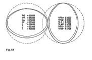
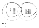
- RG normalized housing radius
- RV normalized virtual housing radius
- RA normalized outer radius of the exactly abschabenden profile
- RF normalized outer radius of the screw to be manufactured
- S normalized play of the screws with each other (gap)
- D normalized play the screw to the housing
- VPR normalized amount of profile shift
- VLR normalized amount of shift of left shaft
- VLW angle of shift of left shaft
- VRR normalized amount of shift of right shaft
- VRW angle of shift of right wave.
- Fig. 1 shows in cross-section two at a distance A from each other exactly abschabende, double-flighted screw elements according to the prior art.
- the screw elements have the same axisymmetric profile.
- the right-hand screw element is rotated by 90 ° with respect to the left-hand side.
- the points marked 1-1 indicate the pivot points of the shafts on which the screw elements are arranged.
- the profile shown is composed of several symmetrical sections. Kinks occur at the transitions of the sections (one of the kinks is indicated by an arrow with 1-2). In the area of the ridge angle KW, the product undergoes a high shear without elongation when operating a multi-screw machine with such screw elements.
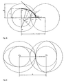
- Fig. 2a shows in cross-section a quarter of the profile of a double-start exactly abschabenden screw element (generating screw element).
- the profile is axisymmetric to the x and y axes so that the entire profile would result from mirroring the shown quarter on the x and y axes.
- the profile of the corresponding (created) The screw element then results by rotation of the profile of the generating screw element by an angle of 90 °.
- the coordinate origin marks in this and all other figures the pivot point D of the shaft. With the outer radius RA, a dashed circle was drawn around the profile.
- the housing bore is represented by a concentric circle with a radius RG which is larger than the outer radius by the clearance S.
- RG RA + S
- the screw profile after Fig. 2a consists of two arcs, which merge without kink. The coordinates of the circular arcs are in Fig. 2a specified.
- the transition from circle 1 to circle 1 'takes place in the point P FP , in which both circles affect the straight line FP.
- Fig. 2b shows by way of example a profile section of a two-speed screw element according to the invention used in three circles.
- the point D indicates the pivot point of the screw element (generating screw element).
- At a distance A from the pivot point D is the fulcrum of the corresponding screw element (generated screw element).
- a circle (inner circle) with the core radius RI and a circle (outer circle) with the outer radius RA of the screw element are shown around the pivot point D.
- Inner circle and outer circle form a circular ring. All points of the profile section as well as of the resulting overall profile of the screw element used according to the invention lie on this circular ring.
- Point P A denotes a starting point of a first circular arc 1 with the radius R 1 and the center M 1 , which lies on the connection path DP A.
- the point P A lies on the outer circle.
- Its center M 3 is on the route DP I.
- Its center M 2 is located at the distance (A / 2) -R 1 from the point P 1 and at the distance R 3 - (A / 2) from the point M 3 .
- the overall profile of the screw element (generating screw element) used according to the invention can be constructed.
- the profile of the corresponding screw element (generated screw element) results here simply by rotation of the profile of the generating screw profile at an angle of 90 ° about the pivot point D.
- Fig. 2c shows an example of screw elements used according to the invention, in which the profile sections indicated by dashed lines can not be brought to coincide with the profile sections marked by solid lines by means of axial reflection. Instead, the profiles are point symmetrical to the pivot point.
- FIG. 3 A particular embodiment of screw elements used according to the invention is exemplified in Fig. 3 shown. It is characterized in that the housing bores are made with a larger radius than the outer radius of the screw profiles and the screw profiles are displaced in pairs relative to the centers of the housing bores, the pivot points (represented by small circles) in the centers of the housing bores, however, be maintained. This surprisingly results in a further, significant reduction in energy input.
- the worm elements rotating eccentrically in this manner can be moved as desired within the housing bores.
- Fig. 3 In the case to be particularly emphasized, it is shown that the two profiles are moved parallel by the same amount in the direction of a straight line passing through the two pivot points, as perpendicularly to it, until they touch the housing contour. This ensures that the screws scrape each other exactly, but only one of the two screw crests of each shaft scrapes the housing exactly. This arrangement has a complete cleaning of all surfaces with simultaneously reduced energy input.
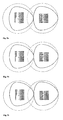
- Fig. 4 shows examples of profiles according to the invention used screw elements with columns (games).
- Fig. 4a was the gap S in the cleaning of the screws with each selected the same size as the gap D in the cleaning of the housing.
- Fig. 4b the gap S is smaller than D and in Fig. 4c and 4d vice versa D is smaller than S.
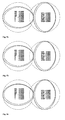
- Fig. 5 It is shown that eccentric profiles used according to the invention are also obtained by constructing a screw profile with gaps and subsequently displacing the profiles within the column.
- the profiles of Figure 5 ad are identical to the profile Figure 4d , The displacement takes place in relation to a straight line through the pivot points of the screw elements in FIG Fig. 5a at an angle of 0 °, in Fig. 5b at an angle of 30 °, in Fig. 5c at an angle of 60 ° and in Fig. 5d at an angle of 90 °.
- Fig. 5 shows examples in which both waves are shifted with the same shift vector. Basically, it is also possible to move both waves within the games with a different vector. One then obtains profiles that clean with a gap that varies during one revolution of the waves.
- Kneading elements with increased dispersing power compared with the conveying thread are obtained by arranging prismatic disks of self-cleaning profiles on the axle rotated by an offset angle relative to one another.
- An example of a kneading element with seven kneading disks arranged at an offset angle of 30 ° on the axis is shown Fig. 6b ,
- FIGS. 1 to 6 only double-flighted screw elements were treated. However, the same principles can also be applied to screw elements with three or more gears.
- Fig. 7 shows in cross section two three-flighted screw elements according to the prior art (see, eg, [1] p. 103).
- the three-string profile in Fig. 7 consists of three symmetrical sections. Kinks occur at the transitions of the sections, and the profile forms the screw crest (marked 7-1 by way of example).
- the profile rotates at a close distance to the housing and impresses with the described disadvantages of the polymer melt a pure shear.
- Fig. 8 shows a profile section of a three-flighted screw element used according to the invention. Since the profile is axisymmetric with respect to three straight lines (S1, S2, S3) arranged at an angle of 60 ° to one another, which pass through the origin of coordinates, only a 60 ° section is shown here. The entire profile results from continuous reflection of the profile curve shown on the mirror straight lines S1, S2 and S3. The profile curve is constructed in the section shown between the lines S1 and S3 of two circular arcs. For the screw results in a convergent-divergent channel, which imprints the mix over its entire circumference a combination of shear and expansion flow.
- the straight line FP runs at a distance of half the center distance from the pivot with a gradient of -1.73.
- the construction shown can be applied analogously for all ratios of external screw radius to center distance of 0.5 to 0.577.
- eccentric rotating profiles can be constructed.
- Such screw profiles are in Fig. 9 ad shown.
- the procedure is analogous to the procedure for the double-flighted profiles.
- the outer radius of the profile is reduced compared to the housing radius and moved the profile in pairs, with the pivot point is maintained centrally to the housing.
- Particularly interesting are snail profiles, where the piebalds among each other completely clean and where the housing is cleaned with only one of three combs.
- Fig. 9a For example, the production of such a profile is shown by shifting the profile horizontally to the right until the right-hand helix crest arrives at the housing contour. With this arrangement, symmetrical flights develop between the profile and the housing.
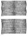
- the three-flighted profiles can be used as a continuous conveyor thread Fig. 10a or as kneading disks Fig. 10b used according to the invention.
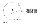
- FIG. 11 shows a profile section of an axisymmetric four-speed worm element used in the invention, which is composed of two circular segments. The design is analogous to apply for all ratios of worm outer radius to center distance of 0.5 to 0.541.
- the four-speed profiles can be used as a continuous conveyor thread Fig. 12a or as kneading disks Fig. 12b be used.
- Profiles with more than four courses used according to the invention can be produced in an analogous manner.
- the column can be varied in a similar manner and eccentric profiles are generated.
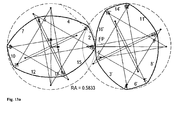
- FIG. 13a schematically an example of a screw element pair used according to the invention is shown in cross section.
- the generating screw profile is represented by the left screw profile.
- the generated screw profile is represented by the right screw profile.
- Both screw profiles consist of 16 circular arcs.
- the circular arcs of the generating and the generated screw profile are characterized by thick, solid lines, which are provided with the respective numbers of circular arcs.
- the centers of the circular arcs are represented by small circles.
- the centers of the circular arcs are connected with thin, solid lines both to the starting point and to the end point of the associated circular arc (boundary lines).
- the external screw radius is the same for the generating profile and the generated screw profile.
- the worm outer radius is characterized by a thin dashed line, in the gusset area by a thin dotted line. Due to the large number of circular arcs and due to the generation of the figures by means of a computer program, it may happen that the numbers of individual circular arcs overlap with boundary lines and are therefore difficult to read. Despite the partial poor readability of individual numbers, the structure of the profiles in connection with this description and the coordinates in the Fig. 13b nevertheless clearly.
- FIG. 13a shows pair of screw profiles used in the invention is point-symmetrical, but not axisymmetric.
- the straight line FP (dotted line) is not affected.
- Such a screw element allows particularly great freedom for the dispersing effect, since the areas before and after the combs, which are crucial for the dispersing effect, can be adapted precisely to the task, without having to take into account the geometrical restriction by the straight line FP.
- Fig. 13b shows for all circular arcs the Fig. 13a the x and y coordinates (Mx and My) of the centers, the radii R and the angles ⁇ of the circular arcs. The angles are given in radians; All other dimensions are normalized to the center distance and therefore dimensionless.
- Plastic compositions which can be extruded according to the invention with high efficiency with simultaneous product protection are, for example, suspensions, pastes, glass, ceramic compositions, metals in the form of a melt, plastics, plastic melts, polymer solutions, elastomer and rubber compositions.
- thermoplastic polymer used is preferably at least one of polycarbonate, polyamide, polyester, in particular polybutylene terephthalate and polyethylene terephthalate, polylactides, polyethers, thermoplastic polyurethane, polyacetal, fluoropolymer, in particular polyvinylidene fluoride, polyethersulfones, polyolefin, in particular polyethylene and polypropylene, polyimide, polyacrylate, in particular poly (Methyl) methacrylate, polyphenylene oxide, polyphenylene sulfide, polyether ketone, polyaryletherketone, styrene polymers, in particular polystyrene, styrene copolymers, in particular styrene-acrylonitrile copolymer, acrylonitrile-butadiene-styrene block copolymers and polyvinyl chloride.
- blends of the listed plastics are so-called blends of the listed plastics, by which the expert understands a combination of two or more plastics.
- polycarbonate and mixtures comprising polycarbonate very particularly preferably polycarbonate, for example obtained by the phase boundary process or the melt transesterification process.
- Other preferred feedstocks are rubbers.
- the rubber at least one of styrene-butadiene rubber, natural rubber, butadiene rubber, isoprene rubber, ethylene-propylene-diene rubber, ethylene-propylene rubber, butadiene-acrylonitrile rubber, hydrogenated nitrile rubber, butyl rubber is preferably used.
- a combination of two or more of the listed rubbers, or a combination of one or more rubber with one or more plastics is of course also possible.
- thermoplastics and elastomers can be used in pure form or as mixtures with fillers and reinforcing materials, in particular glass fibers, as mixtures with one another or with other polymers, or as mixtures with customary polymer additives.
- additives are added to the plastic compositions, in particular the polymer melts and mixtures of polymer melts. These may be added to the extruder as solids, liquids or solutions together with the polymer, or at least some or all of the additives may be fed to the extruder via a side stream.
- Additives can impart a variety of properties to a polymer. These may include, for example, colorants, pigments, processing aids, fillers, antioxidants, reinforcing agents, UV absorbers and light stabilizers, metal deactivators, peroxide scavengers, basic stabilizers, Nucleating agents, benzofurans and indolinones effective as stabilizers or antioxidants, mold release agents, flame retardant additives, antistatic agents, colorants and melt stabilizers. Exemplary of these are carbon black, glass fiber, clay, mica, graphite fiber, titanium dioxide, carbon fibers, carbon nanotubes, ionic liquids and natural fibers
- Extrusion of polypropylene and polypropylene copolymers shows degradation of molecular weight at high temperature. Furthermore, polypropylenes and polypropylene copolymers react with atmospheric oxygen in the autoxidation cycle to produce odorous and hence interfering low molecular weight components such as ketones, aldehydes, carboxylic acids and alcohols.
- hydrochloric acid acts catalytically in the further elimination of hydrochloric acid.
- polyesters such as e.g. Polyethylene terephthalate, Polybutylenterephtaltat, Polytrimethylenterepthalat or polylactides results in too high a temperature and water influence, a reduction in the molecular weight and displacement of the end groups in the molecule. This is especially problematic in the recycling of polyethylene terephthalate.
- Polyethylene terephthalate breaks down acetaldehyde at high temperature, which may, for example, lead to changes in taste in the contents of beverage bottles.
- thermoplastics impact-modified with diene rubbers, in particular with butadiene rubber, in particular impact-modified polystyrene types (HIPS) and impact-modified SAN (acrylonitrile-butadiene-styrene, ABS), carcinogenic butadiene and toxic vinylcyclohexene split off at too high a temperature. Furthermore, the diene rubber cross-links, so that deterioration of the mechanical properties of the product occur.
- HIPS impact-modified polystyrene types
- SAN acrylonitrile-butadiene-styrene, ABS
- thermoplastic polyurethanes In the extrusion of thermoplastic polyurethanes, too high a temperature leads to changes in the molecular structure by transurethanization and, in the presence of water, to molecular weight degradation. Both undesirably affect the properties of the thermoplastic polyurethane.
- diene rubbers such as polybutadiene (BR), natural rubber (NR) and synthetic polyisoprene (IR), butyl rubber (IIR), chlorobutyl rubber (CIIR), bromobutyl rubber (BIIR), styrene-butadiene rubber (SBR), polychloroprene (CR), butadiene-acrylonitrile rubber (NBR), partially hydrogenated butadiene-acrylonitrile rubber (HNBR), and ethylene-propylene-diene copolymers (EPDM) are formed at too high a temperature by crosslinking gel, resulting in deterioration of mechanical properties the components made from it leads.
- BR polybutadiene
- NR natural rubber
- IIR butyl rubber
- CIIR chlorobutyl rubber
- BIIR bromobutyl rubber
- SBR polychloroprene
- NBR butadiene-acrylonitrile rubber
- HNBR partially hydrogenated
- the vulcanizers e.g. Sulfur or peroxides are brought to too high temperatures for premature vulcanization. As a result, no products can be produced from these rubber mixtures.
- degassing extruders are known to those skilled in principle and described for example in [1]. Characteristic of degassing extruders are the so-called degassing mandrels. These are housings with openings through which the resulting vapors can escape. Various vent mandrels are known to operate at different pressures when the product is vented between the vent domes to form a seal between the various pressures.
- the screw elements used according to the invention are preferably used in partially filled zones and more preferably in the degassing zones.
- the product is fed to a liquid-fed degassing extruder with a so-called backward degassing.
- a liquid-fed degassing extruder with a so-called backward degassing.
- an optionally preheated polymer solution is introduced into a twin-screw extruder and foams there.
- the gases are then discharged back through the passages of the twin-screw extruder to a degassing dome.
- backward degassing is well known in the art and e.g. in [1] on pages 193-195.
- the concentration of polycarbonate in the solution in this case is preferably between 55% by mass and 95% by mass, more preferably between 65% by mass and 90% by mass, when entering the extruder.
- a liquid-fed, the degassing extruder to supply the product consists in a flash evaporation at the inlet of the extruder.
- a flash is preferred directly above the extruder, so that the UNEtgaste melt directly on the screw shafts falls.
- the vapors produced in the flash are preferably withdrawn from a separating vessel, which also lies above the extruder, by means of one or more vapor lines.
- the temperature of the polymer solution is preferably in the range of 180 ° C to 300 ° C, more preferably between 200 ° C and 250 ° C.
- the flash is preferably operated in a pressure range between 0.3 bar abs and 6 bar abs, more preferably between 0.5 bar abs and 2 bar abs.
- supplying product to a liquid-fed degassing extruder consists in a tube bundle heat exchanger at the inlet of the extruder, which is arranged above the shafts of the extruder, so that the partially degassed polymer solution emerging from the tubes can fall directly onto the shafts.
- a separating vessel in which vapors and polymer solution are separated from each other and which has at least one outlet for the vapors.
- the polymer solution is introduced through an inlet opening at the upper end of the downpipe evaporator and fed via a distributor plate to a plurality of tubes, which are heated from the outside.
- the heating is preferably carried out by means of condensing steam, a condensing organic heat carrier or a liquid organic heat carrier.
- the heat energy is introduced to evaporate solvent in the polycarbonate melt.
- solvent components evaporate and form a two-phase gas-liquid mixture. This specifically prevents overheating of the polymer melt.
- the escaping vaporous solvent causes a constant mixing and surface renewal of the polymer melt, which causes their more efficient concentration. It is supplied in this way the Ausdampfextruder a much higher concentrated polycarbonate melt, so that both the energy entry and the residence time of the polycarbonate melt in the extruder may be lower in the extruder to cause the same or even higher residual degassing of the polycarbonate melt.
- the concentration of the polymer solution in the tube bundle heat exchanger is preferably between 50 and 80% by weight.
- the heating temperature of the tubes is from 240 ° C to 360 ° C, preferably from 250 ° C to 340 ° C and most preferably from 260 ° C to 300 ° C.
- the polymer concentration at the inlet to the extruder is between 80 and 99% by weight, preferably 90 to 99% by weight.
- the pressure in the separating vessel is preferably between 0.3 bar abs and 6 bar abs, more preferably between 0.5 bar abs and 2 bar abs.
- a foam evaporator may consist of, for example, a tube bundle or a nozzle plate. From the openings of the foam evaporator, the polymer melt foams and is freed of residual solvent except for small residual contents.
- This foam evaporator is preferably arranged above the waves of the extruder so that the polymer solution emerging from the tubes can fall directly onto the waves. Between the outlet of the tube bundle heat exchanger and the extruder shafts is still a separating vessel in which vapors and polymer solution are separated from each other and which has at least one outlet for the vapors.
- the concentration of the polycarbonate solution in the inlet of the foam evaporator is between 90% by weight and 99.95% by weight.
- a foaming agent such as nitrogen, CO 2 , is added to the polycarbonate solution.
- the vapor pressure of the foaming agent together with the residual solvent is 0.1 to 100 bar, preferably 0.5 to 60 bar and particularly preferably 1 to 40 bar.
- the pressure in the separator is through the openings of the foam evaporator, the polymer solution is divided into partial streams between 0.1 and 20 mbar.
- the temperature of the polymer solution is between 250 ° C and 340 ° C.
- the pressure in the separating vessel is preferably between 0.1 and 20 mbar.
- Fig. 14 shows a preferred embodiment in which the screw elements are used in a vented extruder.
- Zone A the polycarbonate solution is added to the extruder through a flash tube 1.
- Zones C, E, GJ and L are degassing zones.
- the released there vapors are withdrawn in the degassing 3 dome.
- Zones B, D, F and H are stagnant zones where a product plug is created by a puffing element that allows adjustment of different pressures in the respective adjacent zones.
- zone K additional entraining agent is added to make the degassing in zone L more effective.
- zone M the polymer is mixed with a side stream of additives and the pressure for the filtration and die following the extruder is established.
- Fig. 15 shows a further preferred embodiment, in which the screw elements are used in a vented extruder.
- zone A the polycarbonate solution is added to the extruder through a vertical preheater 1.
- Zones C, E, GJ and L are degassing zones.
- the released there vapors are withdrawn in the degassing 3 dome.
- Zones B, D, F and H are stagnant zones where a product plug is created by a puffing element that allows adjustment of different pressures in the respective adjacent zones.
- zone K additional entraining agent is added to make the degassing in zone L more effective.
- Zone M the polymer is mixed with a side stream of additives and the pressure for the filtration and die following the extruder is established.
- Fig. 16 shows a further preferred embodiment, in which the screw elements are used in a vented extruder, with a foam evaporator at the inlet.
- zone A the polycarbonate solution is added to the extruder through a foam evaporator 1.
- the vapors are separated in separator 2 from the polycarbonate solution.
- zones B, D, F and H entraining agents are added and dispersed in each case.
- Zones C, E, F, G and J the volatiles are separated from the polymer.
- Zone K the polymer is mixed with a side stream of additives and optionally further polymer, and the pressure for the filtration and the die following the extruder is built up.
- the process according to the invention is particularly preferably used in the production and compounding of polycarbonate.
- it offers advantages especially in the color of the polycarbonate, in non-colored polycarbonate measured with the yellowness index (YI).
- the screw elements used according to the invention are particularly preferably used in the degassing zone.
- Suitable diphenols are, for example, hydroquinone, resorcinol, dihydroxydiphenyl, bis (hydroxyphenyl) alkanes, bis (hydroxyphenyl) -cycloalkanes, bis (hydroxyphenyl) sulfides, bis (hydroxyphenyl) ethers, bis (hydroxyphenyl) ketones , Bis (hydroxyphenyl) sulfones, bis (hydroxyphenyl) sulfoxides, ⁇ , ⁇ '-bis (hydroxyphenyl) diisopropylbenzenes, and their alkylated, nuclear alkylated and nuclear halogenated compounds.
- Preferred diphenols are 4,4'-dihydroxydiphenyl, 2,2-bis (4-hydroxyphenyl) -1-phenyl-propane, 1,1-bis (4-hydroxyphenyl) -phenyl-ethane, 2,2-bis- (4-hydroxyphenyl) propane, 2,4-bis (4-hydroxyphenyl) -2-methylbutane, 1,3-bis [2- (4-hydroxyphenyl) -2-propyl] benzene (bisphenol M), 2, 2-bis (3-methyl-4-hydroxyphenyl) -propane, bis (3,5-dimethyl-4-hydroxyphenyl) -methane, 2,2-bis (3,5-dimethyl-4-hydroxyphenyl) - propane, bis (3,5-dimethyl-4-hydroxyphenyl) sulfone, 2,4-bis- (3,5-dimethyl-4-hydroxyphenyl) -2-methylbutane, 1,3-bis- [2- (2-methyl) 3,5-dimethyl-4-hydroxyphenyl)
- diphenols are 4,4'-dihydroxydiphenyl, 1,1-bis (4-hydroxyphenyl) -phenyl-ethane, 2,2-bis (4-hydroxyphenyl) -propane, 2,2-bis (3,5 -dimethyl-4-hydroxyphenyl) -propane, 1,1-bis (4-hydroxyphenyl) cyclohexane and 1,1-bis (4-hydroxyphenyl) -3,3,5-trimethylcyclohexane (bisphenol TMC).
- the monochromatic chain terminators needed to control the molecular weight such as phenol or alkylphenols, in particular phenol, p-tert. Butylphenol, isoOctylphenol, cumylphenol, their chlorocarbonic acid esters or acid chlorides of monocarboxylic acids or mixtures of these chain terminators are fed either with the bisphenolate or the bisphenolates of the reaction or added at any time during the synthesis, as long as phosgene or Chlorkohlenquipreend phenomenon are present in the reaction mixture or, in the case of the acid chlorides and chloroformates as chain terminators, as long as enough phenolic end groups of the forming polymer are available.
- the chain terminator (s) are added after phosgenation at one site or at a time when phosgene is no longer present but the catalyst has not yet been metered. Alternatively, they may also be added upstream of the catalyst, together with the catalyst or in parallel.
- branching or branching mixtures are added to the synthesis.
- branching agents are added before the chain terminators.
- trisphenols, quarterphenols or acid chlorides of tri- or tetracarboxylic acids or mixtures of the polyphenols or the acid chlorides are used.
- branching compounds having three or more than three phenolic hydroxyl groups include, for example, phloroglucinol, 4,6-dimethyl-2,4,6-tri- (4-hydroxyphenyl) -hepten-2, 4,6-dimethyl-2, 4,6-tri- (4-hydroxyphenyl) -heptane, 1,3,5-tri (4-hydroxyphenyl) -benzene, 1,1,1-tri- (4-hydroxyphenyl) -ethane, tri- (4 -hydroxyphenyl) -phenylmethane, 2,2-bis (4,4-bis (4-hydroxyphenyl) cyclohexyl] -propane, 2,4-bis- (4-hydroxyphenyl-isopropyl) -phenol, tetra- (4 hydroxyphenyl) methane.
- trifunctional compounds are 2,4-dihydroxybenzoic acid, trimesic acid, cyanuric chloride and 3,3-bis (3-methyl-4-hydroxyphenyl) -2-oxo-2,3-dihydroindole.
- Preferred branching agents are 3,3-bis (3-methyl-4-hydroxyphenyl) -2-oxo-2,3-dihydroindole and 1,1,1-tri- (4-hydroxyphenyl) -ethane.
- the catalysts preferably used in the phase interface synthesis of polycarbonate are tertiary amines, especially triethylamine, tributylamine, trioctylamine, N-ethylpiperidine, N-methylpiperidine, Ni / n-propylpiperidine, quaternary ammonium salts such as tetrabutylammonium, tributylbenzylammonium, tetraethylammonium hydroxide, chloride, bromide, hydrogen sulfate, - tetrafluoroborate, as well as the ammonium compounds corresponding phosphonium compounds.
- tertiary amines especially triethylamine, tributylamine, trioctylamine, N-ethylpiperidine, N-methylpiperidine, Ni / n-propylpiperidine, quaternary ammonium salts such as tetrabutylammonium, tribu
- the catalysts may be added singly, in admixture or also side by side and sequentially to the synthesis, if appropriate also prior to phosgenation, but preferred are doses after phosgene introduction, unless an onium compound or a mixture of onium compounds is used as catalysts. In this case, addition before the phosgene dosage is preferred.
- the dosage of the catalyst or catalysts can in bulk, in an inert solvent, preferably the solvent of the polycarbonate synthesis or as an aqueous solution, in the case of tert. Amines then as their ammonium salts with acids, preferably mineral acids, in particular hydrochloric acid, take place.
- the total amount of catalysts used is from 0.001 to 10 mol% based on moles of bisphenols, preferably 0.01 to 8 mol%, particularly preferably 0.05 to 5 mol%.
- the polycarbonate synthesis can be carried out continuously or batchwise.
- the reaction can therefore be carried out in stirred tanks, tubular reactors, pumped-circulation reactors or stirred tank cascades or combinations thereof.
- it must be ensured by using the above-mentioned mixing devices that the aqueous and organic phases separate as far as possible only when the synthesis mixture has reacted, ie. contains no saponifiable chlorine of phosgene or chloroformates.
- the organic phase may consist of a solvent or mixtures of several solvents.
- Suitable solvents are chlorinated hydrocarbons (aliphatic and / or aromatic), preferably dichloromethane, trichlorethylene, 1,1,1-trichloroethane, 1,1,2-trichloroethane and chlorobenzene and mixtures thereof.
- aromatic hydrocarbons such as benzene, toluene, m / p / o-xylene, or aromatic ethers, such as anisole alone, may also be used in admixture with or in addition to chlorinated hydrocarbons.
- Another embodiment of the synthesis uses solvents which do not dissolve polycarbonate but only swell.
- solvents which are soluble in the aqueous phase such as tetrahydrofuran, 1,3 / 1,4-dioxane or 1,3-dioxolane, can also be used as solvents if the solvent partner forms the second organic phase.
- the reacted, at most still traces ( ⁇ 2 ppm) of chlorocarbonic containing at least two-phase reaction mixture is allowed to settle for phase separation.
- the aqueous alkaline phase is possibly recycled wholly or partly back into the Polycarbonatsynthese as aqueous phase or fed to the wastewater treatment, where solvent and catalyst components are separated and recycled.
- the salt is separated off after separation of the organic impurities, in particular of solvents and polymer residues, and optionally after the setting of a certain pH, for example by adding sodium hydroxide, which can be supplied to the chloralkali electrolysis, for example, while the aqueous phase optionally recycled to the synthesis.
- the organic, the polycarbonate-containing phase can now be cleaned of all contaminants alkaline, ionic or catalytic type.
- the organic phase contains even after one or more settling still shares the aqueous alkaline phase in fine droplets and the catalyst, usually a tert. Amine.
- the settling operations can be assisted by passing the settling vessel, stirred tank, coalescer or separators or combinations thereof through the organic phase, it being possible for water to be metered in each or some separation steps under certain circumstances using active or passive mixing devices.
- aqueous phase After this coarse separation of the alkaline, aqueous phase, the organic phase is washed one or more times with dilute acids, mineral, carbon hydroxycarboxylic and / or sulfonic acids. Preference is given to aqueous mineral acids, in particular hydrochloric acid, phosphorous acid and phosphoric acid or mixtures of these acids. The concentration of these acids should be in the range of 0.001 to 50% by weight, preferably 0.01 to 5% by weight.
- the organic phase is repeatedly washed with desalted or distilled water.
- acids preferably dissolved in the solvent, which is the basis of the polymer solution, may be added between these washing steps or else after the washing.
- Hydrogen chloride gas and phosphoric acid or phosphorous acid are preferably used here, which can optionally also be used as mixtures.
- the plastic compositions obtained by the process according to the invention can be provided to modify properties with the customary additives and additives (for example auxiliaries and reinforcing substances).
- additives and additives serves the extension of the useful life (eg hydrolysis or degradation stabilizers), the improvement of color stability (eg thermal and UV stabilizers), the simplification of processing (eg demulsifier, flow aids), the improvement of performance characteristics (eg Antistatic agents), improving the flame retardant, influencing the visual impression (eg organic colorants, pigments) or the adaptation of the polymer properties to certain loads (impact modifiers, finely divided minerals, fiber, quartz, glass and carbon fibers).
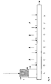
- Point B1 is the so-called turbine point. If the throughput is greater than B1, power is delivered to the screw shafts.
- the operating point B2 indicates the power requirement without throughput.
- the plastic mass used was a Newtonian flow fluid. As substance data typical values were used, as for example from the book Polymer Processing 2002, VDI-K, VDI-Verlag, Dusseldorf, 2002 on page 159 can be removed.
- the density of the plastic mass is 1000 kg / m 3 .
- the viscosity of the plastic mass is 1000 Pa * s.
- the thermal conductivity of the plastic mass is 0.2 W / m / K.
- the heat capacity of the plastic mass is 2000 J / kg / K.
- the geometry of the conveyor element according to the prior art can from the FIGS. 17a to 17c be removed.
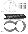
- the Figure 17a shows in cross section a quarter of a screw profile of a screw element with a Erdmenger screw profile according to the prior art.
- the circular arcs of the screw profile are characterized by thick, solid lines, which are provided with the respective numbers of circular arcs.
- the centers of the circular arcs are represented by small circles.
- the centers of the circular arcs are connected by thin, solid lines both to the starting point and to the end point of the associated circular arc.
- the straight line FP is represented by a thin, dotted line.
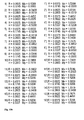
- the dimensionless outer screw radius RA is characterized by a thin, dashed line, the numerical value of which is indicated at the bottom right in the figure to four significant digits. To the right of the figure, for each arc, the radius R, the angle ⁇ , and the x and y coordinates of the arc midpoint Mx and My are given in four significant digits, respectively. This information clearly defines the screw profile.
- the screw profile is mirror-symmetrical to the x and y axes, so that the entire screw profile is obtained by mirroring the quarter shown on the x and y axes.
- Screw profiles in which one quarter of the screw profile consists of a total of n circular arcs, are referred to below as n-circle screw profiles.
- the numbering of circular arcs of an n-circle screw profile in the Figure 17a is performed such that the first n / 2 circular arcs are numbered 1 to n / 2 in ascending order and the last n / 2 circular arcs are numbered in descending order (n / 2) 'to 1'.
- Each circular arc i of the screw profile corresponds to a circular arc i 'of the screw profile.
- the Figure 17a shows a quarter of a two-speed Erdmenger screw profile according to the prior art, which is composed of 4 circular arcs.
- the angles ⁇ _1, ⁇ _2, ⁇ _2 'and ⁇ _1' depend on the external screw radius and the axial distance.
- the angle ⁇ _1 is equal to half the crest angle of a two-speed Erdmenger screw profile.
- the Erdmenger screw profile has a kink at the location of the radius R_2.
- the "size of the bend" is given by the angle ⁇ _2, ie the transition from the circular arc 1 to the circular arc 2 'takes place by rotation about the angle ⁇ _2.
- FIG. 17b shows a pair of screw elements, formed as conveying elements, the screw profile on Figure 17a based.
- the housing is represented by thin, solid lines on the left and right of the two conveyor elements.
- a possible computing grid is also shown, which can be used to calculate the flow in two- and multi-shaft extruders.
- the number of grid elements in the circumferential direction is equal to 180 and in the axial direction equal to 90.
- FIG. 17c shows a plan view of the pair of screw elements FIG. 17b .
- the free volume between the conveyor elements and the housing is provided with a possible computational grid, which can be used to calculate the flow in twin and multi-screw extruders.
- the number of grid elements in the circumferential direction is equal to 180 and in the radial direction equal to 10.
- the axes of rotation of the two screw elements are marked by small circles.
- a computational grid is used, the 320 grating elements in the circumferential direction, 160 grid elements in the axial direction and 12 grating elements in the radial direction.
- the maximum pressure build-up efficiency is 7.32%.
- the calculation grid was calculated according to FIGS. 17b and 17c used.
- the velocity and pressure field was initialized with a zero vector.
- the pressure gradient along the axes of rotation has been set to 0 so that the throughput A1 is set as throughput.
- the temperature field was initialized at 300 ° C. Both the housing wall and the surface of the two conveyor elements were assumed to be adiabatic.
- the development of the temperature field was followed over two revolutions of the extruder.
- the time step size was 0.000925926 s.
- the speed of the twin-screw extruder was 360 rpm.
- the maximum temperature in the computing area was reached.
- the maximum temperature is practically the same temperature level on the surfaces of the two conveying elements and indeed in the comb areas that just clean the housing.
- the maximum temperature is calculated to be about 400 ° C.
- FIGS. 18a to 18c out The geometry of a conveyor element used in the invention is derived from the FIGS. 18a to 18c out.
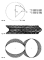
- FIG. 18a shows in cross section a quarter of a screw profile of a screw element used in the invention.
- the structure of the figure is analogous to Figure 17a and already described in detail there.
- the quarter of the screw profile consists of 2 circular arcs. Characteristic of this screw profile is further that the screw profile contains no kink and that the crest angle of the comb area, ie a region which lies on the outer screw radius, is equal to 0.
- the FIG. 18b shows a pair of screw elements, formed as conveying elements, the screw profile on FIG. 18a based.
- the housing is represented by thin, solid lines on the left and right of the two conveyor elements.
- a possible computing grid is also shown, which can be used to calculate the flow in two- and multi-shaft extruders.
- the number of grid elements in the circumferential direction is equal to 180 and in the axial direction equal to 90.
- FIG. 18c shows a plan view of the pair of screw elements FIG. 18b .
- the free volume between the conveyor elements and the housing is provided with a possible computational grid, which can be used to calculate the flow in twin and multi-screw extruders.
- the number of grid elements in the circumferential direction is equal to 180 and in the radial direction equal to 10.
- the axes of rotation of the two screw elements are marked by small circles.
- a computational grid having 320 grating elements in the circumferential direction, 160 grating elements in the axial direction and 12 grating elements in the radial direction is used.
- the maximum efficiency in pressure build-up is 9.05%.
- the performance parameter B2 is about 17% lower in the case of the conveying element used according to the invention than in the case of a conveying element with a double-flight Erdmenger screw profile according to the prior art from Example 1.
- a lower energy input reduces the temperature increase and as a consequence the undesired polymer damage.
- the calculation grid was calculated according to FIGS. 17b and 17c used.
- the velocity and pressure field was initialized with a zero vector.
- the pressure gradient along the axes of rotation has been set to 0 so that the throughput A1 is set as throughput.
- the temperature field was initialized at 300 ° C. Both the housing wall and the surface of the two conveyor elements were assumed to be adiabatic.
- the development of the temperature field was followed over two revolutions of the extruder.
- the time step size was 0.000925926 s.
- the speed of the twin-screw extruder was 360 rpm.
- the maximum temperature in the computing area was searched.
- the maximum temperature is practically the same temperature level on the surfaces of the two conveying elements and that on a surface just next to the minimized comb areas, which are currently in the gusset area, ie in the area in which the two housing bores penetrate each other.
- the maximum temperature is about 365 ° C according to calculations.
- the maximum surface temperature on the minimized comb areas just cleaning the housing is about 340 ° C according to calculations.
- Example 2 In comparison with the conveyor element according to the prior art from Example 1 is achieved with the conveyor element according to the invention used in Example 2 by about 35 ° C lower peak temperature. With regard to the comb areas, there is even a temperature difference of about 60 ° C. Assuming that the reaction rate constant of a polymer damage reaction doubles per 10 ° C increase in temperature results in about 50 times faster polymer damage in the area of the screw flights of the conveyor element according to Example 1 as in the area of the screw flights of the conveyor element according to Example 2.
Landscapes
- Engineering & Computer Science (AREA)
- Mechanical Engineering (AREA)
- Mathematical Optimization (AREA)
- Algebra (AREA)
- General Physics & Mathematics (AREA)
- Mathematical Analysis (AREA)
- Physics & Mathematics (AREA)
- Mathematical Physics (AREA)
- Pure & Applied Mathematics (AREA)
- Manufacturing & Machinery (AREA)
- Extrusion Moulding Of Plastics Or The Like (AREA)
- Processing And Handling Of Plastics And Other Materials For Molding In General (AREA)
- Gears, Cams (AREA)
Claims (14)
- Procédé d'extrusion de pâtes plastiques par recours à des éléments hélicoïdaux pour machines à plusieurs arbres hélicoïdaux dotées d'arbres hélicoïdaux tournant par paires dans le même sens et se raclant deux à deux de manière exacte et présentant deux ou plusieurs pas hélicoïdaux,
la totalité de la section transversale des profils hélicoïdaux pouvant tous être représentés par une courbe profilée à différentielle croissante,
des jeux de l'ordre de 0,1 à 0,001 par rapport au diamètre du profil hélicoïdal étant prévus entre les éléments hélicoïdaux et le boîtier et/ou entre des éléments hélicoïdaux voisins,
la totalité de la section transversale du profil hélicoïdal étant constituée de l'assemblage d'au moins quatre arcs de cercle, les arcs de cercle se prolongeant tangentiellement l'un dans l'autre en leur point initial et leur point terminal,
le procédé étant caractérisé en ce que- l'axe du profil hélicoïdal générateur et l'axe du profil hélicoïdal généré présentant un écart mutuel a,- le nombre des arcs de cercle du profil hélicoïdal généré est n,- le rayon extérieur ra du profil hélicoïdal généré est supérieur à 0 (ra > 0) et inférieur à l'écart entre les axes (ra < a),- le rayon d'âme ri du profil hélicoïdal généré est supérieur à 0 (ri > 0) et inférieur ou égal à ra (ri ≤ ra),- tous les arcs de cercle du profil hélicoïdal générateur se prolongent tangentiellement l'un dans l'autre,- les arcs de cercle forment un profil hélicoïdal fermé, autrement dit, la somme des angles αj de tous les arcs de cercle j est égale à 2π□, π représentant 3,14159,- les arcs de cercle forment un profil hélicoïdal convexe,- chacun des arcs de cercle du profil hélicoïdal générateur est situé à l'intérieur ou sur les limites d'un anneau circulaire de rayon extérieur ra et de rayon d'âme ri dont le centre est situé sur le centre de rotation du profil hélicoïdal générateur,- au moins l'un des arcs de cercle du profil hélicoïdal générateur touche le rayon extérieur ra du profil hélicoïdal généré en un point PA,- au moins l'un des arcs de cercle du profil hélicoïdal générateur touche le rayon d'âme ri du profil hélicoïdal générateur en un point PI,- le nombre des arcs de cercle n' du profil hélicoïdal généré est égal au nombre des arcs de cercle n du profil hélicoïdal générateur,- le rayon extérieur ra' du profil hélicoïdal généré est égal à la différence entre l'écart entre les axes et le rayon d'âme ri du profil hélicoïdal générateur (ra' = a - ri),- le rayon d'âme ri' du profil hélicoïdal généré est égal à la différence entre l'écart entre les axes et le rayon extérieur ra du profil hélicoïdal générateur (ri' = a - ra),- l'angle αj' de l'arc de cercle j' du profil hélicoïdal généré est égal à l'angle αj de l'arc de cercle j du profil hélicoïdal générateur, j et j' étant des nombres entiers qui traversent ensemble toutes les valeurs comprises entre 1 et le nombre n ou n' des arcs de cercle,- la somme du rayon rj' de l'arc de cercle j' du profil hélicoïdal généré et le rayon rj de l'arc de cercle j du profil hélicoïdal générateur est égale à l'écart a entre les axes, j et j' étant des nombres entiers qui traversent ensemble toutes les valeurs comprises entre 1 et le nombre n ou n' des arcs de cercle,- le centre de l'arc de cercle j' du profil hélicoïdal généré présente par rapport au centre de l'arc de cercle j du profil hélicoïdal générateur une distance égale à la distance a entre les axes et le centre de l'arc de cercle j' du profil hélicoïdal généré présente par rapport au centre de rotation du profil hélicoïdal généré une distance égale à la distance entre le centre de l'arc de cercle j du profil hélicoïdal générateur par rapport au centre de rotation du profil hélicoïdal générateur et la ligne de liaison entre le centre de l'arc de cercle j' du profil hélicoïdal généré et le centre de l'arc de cercle j du profil hélicoïdal générateur est une parallèle à la ligne de liaison entre le centre de rotation du profil hélicoïdal généré et le centre de rotation du profil hélicoïdal générateur, j et j' étant des nombres entiers qui traversent ensemble toutes les valeurs comprises entre 1 et le nombre n ou n' des arcs de cercle et- un point initial de l'arc de cercle j' du profil hélicoïdal généré est situé par rapport au centre de l'arc de cercle j' du profil hélicoïdal généré dans une direction opposée à la direction qui présente un point initial de l'arc de cercle j du profil hélicoïdal générateur par rapport au centre de l'arc de cercle j du profil hélicoïdal générateur, j et j' étant des nombres entiers qui traversent ensemble toutes les valeurs comprises entre 1 et le nombre n ou n' des arcs de cercle. - Procédé selon la revendication 1, caractérisé en ce que les éléments hélicoïdaux présentent une symétrie ponctuelle et en ce que dans une partie représentant 360°/(2.Z), les courbes profilés sont constituées de l'assemblage de deux arcs de cercle, Z étant le nombre de pas des éléments hélicoïdaux.
- Procédé selon l'une des revendications 1 ou 2, caractérisé en ce que les éléments hélicoïdaux présentent une symétrie axiale et en ce que dans une fraction représentant 360°/(2.Z), la courbe profilée est constituée d'au moins deux arcs de cercle, Z représentant le nombre de pas des éléments hélicoïdaux.
- Procédé selon la revendication 3, caractérisé en ce que dans la partie, la courbe profilée est constituée de deux arcs de cercle, les arcs de cercle se prolongeant l'un dans l'autre à différentielle croissante en un point PFP, le point PFP étant situé sur une droite FP dont la perpendiculaire au point PFP passe par le centre des deux arcs de cercle.
- Procédé selon la revendication 4, caractérisé en ce que les éléments hélicoïdaux un centre de rotation D, un point PA situé sur un cercle qui entoure le centre de rotation et dont le rayon extérieur est le rayon ra de l'élément hélicoïdal, un point PI situé sur un cercle qui entoure le centre de rotation à un rayon intérieur ri de l'élément hélicoïdal, une droite DPA qui passe par les points PA et D et une droite DPI qui passe par les points PI et D, qui, lorsque l'on utilise un système de coordonnées cartésiennes, le point D étant à l'origine et le point PA sur l'axe x, est caractérisé en ce que
la normale coupe la droite DPA au centre de l'un des arcs de cercle et la droite DPI coupe le centre de l'autre arc de cercle et en ce que la droite FP présente par rapport au centre de rotation une distance qui correspond à la moitié de la distance a entre les axes et une pente angulaire de -1/tan(π/(2.Z)). - Procédé selon l'une des revendications précédentes, caractérisé en ce que les éléments hélicoïdaux sont configurés comme éléments de mélange ou éléments de transport.
- Procédé selon l'une des revendications précédentes, caractérisé en ce que les éléments hélicoïdaux sont configurés comme éléments de pétrissage.
- Procédé selon l'une des revendications précédentes, caractérisé en ce que les éléments hélicoïdaux sont utilisés dans une zone de dégazage ou une zone de transport.
- Procédé selon l'une des revendications précédentes, caractérisé en ce que les pâtes plastiques sont des thermoplastiques ou des élastomères.
- Procédé selon la revendication 9, caractérisé en ce qu'il utilise comme thermoplastiques les polycarbonates, les polyamides, les polyesters, notamment le poly(téréphtalate de butylène) et le poly(téréphtalate d'éthylène), les polyéthers, les polyuréthanes thermoplastiques, les polyacétals, les polymères fluorés, notamment le poly(fluorure de vinylidène), les polyéthersulfones, les polyoléfines, notamment le polyéthylène et le polypropylène, les polyimides, les polyacrylates, notamment le poly(métacrylate de méthyle), le poly(oxyde de phénylène), le poly(sulfure de phénylène), les polyéthercétones, les poly(aryléthercétones), les polymères de styrène, notamment le polystyrène, les copolymères de styrène, notamment les copolymères de styrène et d'acrylonitrile, les copolymères séquencés d'acryle, nitrile, butadiène et styrène, le poly(chlorure de vinyle) ou un mélange d'au moins deux de ces thermoplastiques.
- Procédé selon la revendication 10, caractérisé en ce qu'il utilise comme thermoplastiques le polycarbonate ou un mélange de polycarbonate et d'autres polymères.
- Procédé selon la revendication 11, caractérisé en ce que le polycarbonate a été préparé par un procédé à surface frontière ou par un procédé d'estérification à l'état fondu.
- Procédé selon la revendication 9, caractérisé en ce qu'il utilise comme élastomères un caoutchouc de styrène et de butadiène, un caoutchouc naturel, un caoutchouc de butadiène, un caoutchouc d'isoprène, un caoutchouc d'éthylène, de propylène et de diène, un caoutchouc d'éthylène et de propylène, un caoutchouc de butadiène et d'acrylonitrile, un caoutchouc nitrile hydrogéné, un caoutchouc de butyle, un caoutchouc d'halogénobutyle, un caoutchouc au chloroprène, un caoutchouc à l'éthylène-acétate de vinyle, un caoutchouc de polyuréthane, un polyuréthane thermoplastique, le guttapercha, un caoutchouc à l'arylate, un caoutchouc fluoré, un caoutchouc au silicone, un caoutchouc au sulfure, un caoutchouc au chlorosulfonyle et polyéthylène ou une combinaison d'au moins deux de ces élastomères.
- Procédé selon l'une des revendications précédentes, caractérisé en ce que des substances de charge ou de renfort, des additifs polymères, des pigments organiques ou minéraux ou des mélanges de ces substances sont ajoutés au polymère.
Applications Claiming Priority (2)
| Application Number | Priority Date | Filing Date | Title |
|---|---|---|---|
| DE102008029303A DE102008029303A1 (de) | 2008-06-20 | 2008-06-20 | Schneckenelemente mit verbesserter Dispergierwirkung und geringem Energieeintrag |
| PCT/EP2009/004248 WO2009153000A1 (fr) | 2008-06-20 | 2009-06-12 | Procédé d'extrusion de matières plastiques |
Publications (2)
| Publication Number | Publication Date |
|---|---|
| EP2291271A1 EP2291271A1 (fr) | 2011-03-09 |
| EP2291271B1 true EP2291271B1 (fr) | 2013-05-01 |
Family
ID=41018355
Family Applications (3)
| Application Number | Title | Priority Date | Filing Date |
|---|---|---|---|
| EP09765548.4A Not-in-force EP2303531B1 (fr) | 2008-06-20 | 2009-06-06 | Éléments de vis sans fin à effet dispersant amélioré et à apport d'énergie réduit |
| EP13152241.9A Active EP2586584B1 (fr) | 2008-06-20 | 2009-06-06 | Éléments de vis sans fin à effet dispersant amélioré et à apport d'énergie rèduit |
| EP09765580.7A Not-in-force EP2291271B1 (fr) | 2008-06-20 | 2009-06-12 | Procédé d'extrusion de matières plastiques |
Family Applications Before (2)
| Application Number | Title | Priority Date | Filing Date |
|---|---|---|---|
| EP09765548.4A Not-in-force EP2303531B1 (fr) | 2008-06-20 | 2009-06-06 | Éléments de vis sans fin à effet dispersant amélioré et à apport d'énergie réduit |
| EP13152241.9A Active EP2586584B1 (fr) | 2008-06-20 | 2009-06-06 | Éléments de vis sans fin à effet dispersant amélioré et à apport d'énergie rèduit |
Country Status (13)
| Country | Link |
|---|---|
| US (4) | US9688002B2 (fr) |
| EP (3) | EP2303531B1 (fr) |
| JP (2) | JP5518853B2 (fr) |
| KR (1) | KR101638638B1 (fr) |
| CN (3) | CN102066065B (fr) |
| BR (1) | BRPI0915804B1 (fr) |
| CA (1) | CA2728438C (fr) |
| DE (2) | DE102008029303A1 (fr) |
| ES (3) | ES2430591T3 (fr) |
| RU (2) | RU2516172C2 (fr) |
| SG (1) | SG192414A1 (fr) |
| TW (1) | TWI530381B (fr) |
| WO (2) | WO2009152968A1 (fr) |
Families Citing this family (32)
| Publication number | Priority date | Publication date | Assignee | Title |
|---|---|---|---|---|
| JP2627842B2 (ja) | 1991-11-28 | 1997-07-09 | 日立造船株式会社 | 船舶用エンジンの給排気系の異常診断方法 |
| JP3868757B2 (ja) * | 2001-04-25 | 2007-01-17 | 株式会社神戸製鋼所 | ゴム系組成物の混練装置および混練方法 |
| JP4445478B2 (ja) * | 2006-03-10 | 2010-04-07 | 株式会社日本製鋼所 | プラスチック原料の可塑化混練押出機 |
| DE102009013418A1 (de) | 2009-03-18 | 2010-09-23 | Bayer Technology Services Gmbh | Verfahren zur Dispersion von Nanopartikeln in fluiden Medien |
| BR112012001023B1 (pt) | 2009-07-16 | 2019-04-02 | Josef A. Blach | Extrusor |
| JP5318709B2 (ja) * | 2009-08-26 | 2013-10-16 | ポリプラスチックス株式会社 | スクリューエレメントピース及びスクリュー |
| CN102741033B (zh) * | 2009-12-04 | 2015-01-07 | 联合碳化化学及塑料技术有限责任公司 | 挤出机螺杆 |
| AT509710B1 (de) | 2010-03-24 | 2011-11-15 | Josef Ing Blach | Extruder |
| TWI577530B (zh) | 2010-07-14 | 2017-04-11 | 科思創德意志股份有限公司 | 製造複合色料之方法與設備 |
| JP5406173B2 (ja) * | 2010-12-28 | 2014-02-05 | ポリプラスチックス株式会社 | 熱可塑性樹脂組成物の製造方法 |
| JP5645133B2 (ja) | 2011-07-14 | 2014-12-24 | 株式会社栗本鐵工所 | 混練撹拌装置 |
| SA112330882B1 (ar) * | 2011-09-28 | 2018-01-24 | ارلانكسيو دوتشلاند جى ام بى اتش. | جهاز لإزالة مكونات متطايرة من وسط يحتوي على بوليمر |
| CN104169063B (zh) | 2012-02-28 | 2016-08-17 | 思蒂亚工程私人有限公司 | 挤出机混合元件 |
| AT512974B1 (de) | 2012-05-23 | 2015-02-15 | Josef A Ing Blach | Mehrwellenextruder |
| JP6038557B2 (ja) * | 2012-09-06 | 2016-12-07 | トヨタ自動車株式会社 | 電極ペースト製造装置および電極ペースト製造方法 |
| TWI649180B (zh) | 2013-04-04 | 2019-02-01 | 艾朗希歐德意志有限公司 | 用於自含彈性體媒介移除揮發性組份之方法及為此目的之去揮發物設備 |
| JP6513647B2 (ja) * | 2013-06-24 | 2019-05-15 | コベストロ、ドイチュラント、アクチエンゲゼルシャフトCovestro Deutschland Ag | 多軸スクリュー式機械用のスクリューエレメント |
| JP5761871B2 (ja) | 2013-08-23 | 2015-08-12 | 株式会社日本製鋼所 | 繊維強化樹脂組成物の製造に使用される二軸押出機及び繊維強化樹脂組成物の製造方法 |
| JP6092832B2 (ja) * | 2014-10-21 | 2017-03-08 | 株式会社日本製鋼所 | 流動挙動予測装置、その流動挙動予測方法および流動挙動予測プログラム |
| DE102015014865A1 (de) * | 2015-11-17 | 2017-05-18 | Siegward Rockstedt | Mehrwellige kontinuierlich arbeitende Misch- und Knetmaschine für plastifizierbare Massen |
| EP3281767A1 (fr) * | 2016-08-11 | 2018-02-14 | Coperion GmbH | Procede et dispositif de fabrication d'une feuille pour dispositif de stockage d'energie electrique |
| CN107139424B (zh) * | 2017-07-07 | 2023-07-21 | 中国石油大学(华东) | 一种全光滑的双螺杆挤出机螺杆转子 |
| US20200247009A1 (en) * | 2017-08-31 | 2020-08-06 | Exxonmobil Chemical Patents Inc. | Methods of Making Thermoplastic Vulcanizates |
| WO2019070796A1 (fr) * | 2017-10-05 | 2019-04-11 | Corning Incorporated | Éléments de malaxage pour appareil d'extrusion et procédés de fabrication d'un corps en nid d'abeilles |
| US12076903B2 (en) * | 2017-10-05 | 2024-09-03 | Corning Incorporated | Screw elements for extrusion apparatus and methods of manufacturing a honeycomb body |
| EP3930983B1 (fr) * | 2019-02-27 | 2022-12-28 | Covestro Intellectual Property GmbH & Co. KG | Élément à vis sans fin à profil de vis sans fin non axisymétrique et son utilisation |
| CN110787748B (zh) * | 2019-11-04 | 2022-02-15 | 江阴市澄阳新技术有限公司 | 搅拌轴及具有其的反应釜 |
| CN114730348B (zh) * | 2019-11-26 | 2026-03-03 | 巴斯夫欧洲公司 | 成形体的几何形状和制造工具的优化 |
| EP4232259B1 (fr) * | 2020-10-22 | 2025-07-09 | Covestro Deutschland AG | Extrudeuse comprenant un système spécial d'éléments à vis sans fin asymétriques sur les arbres de vis sans fin |
| US20230045894A1 (en) * | 2021-08-13 | 2023-02-16 | Seattle Food Tech, Inc. | Asymmetric fluted infeeds |
| JP7075707B1 (ja) | 2021-12-28 | 2022-05-26 | 株式会社Steer Japan | 溶融混練押出装置の運転の際に必要なエネルギーを低減可能とする方法 |
| CN120493431B (zh) * | 2025-05-07 | 2026-06-12 | 宜春万申智能装备股份有限公司 | 一种盘状制粒块及其动态啮合间隙分析方法 |
Family Cites Families (33)
| Publication number | Priority date | Publication date | Assignee | Title |
|---|---|---|---|---|
| DE862668C (de) | 1944-07-07 | 1953-01-12 | Bayer Ag | Vorrichtung zum Verkneten, Gelatinieren und Verpressen von plastischen Massen |
| CA836936A (en) * | 1962-03-21 | 1970-03-17 | A. Loomans Bernard | Continuous mixer |
| US3900187A (en) * | 1973-10-29 | 1975-08-19 | Baker Perkins Inc | Continuous mixing and/or kneading machine with co-wiping single lead screws |
| US4063717A (en) * | 1977-02-01 | 1977-12-20 | E. I. Du Pont De Nemours And Company | Multivented twin-screw extruder |
| DE3206325C2 (de) | 1982-02-22 | 1985-10-10 | AUTOMATIK Apparate-Maschinenbau GmbH, 8754 Großostheim | Mehrwellige, kontinuierlich arbeitende Misch- und Knetmaschine für plastifizierbare Massen |
| DE3412258A1 (de) * | 1984-04-02 | 1985-10-10 | Werner & Pfleiderer, 7000 Stuttgart | Gleichdrall-doppelschneckenkneter mit knetscheiben |
| SU1634511A2 (ru) * | 1988-07-04 | 1991-03-15 | Тамбовское Научно-Производственное Объединение Полимерного Машиностроения "Полимермаш" | Черв чный смеситель дл переработки полимеров |
| DE3841728C1 (de) * | 1988-12-10 | 1990-03-01 | Hermann Berstorff Maschinenbau Gmbh, 30627 Hannover | Ein- oder Doppelschneckenextruder zum Einarbeiten von pulverförmigen oder faserförmigen Additiven in eine thermoplastische Kunststoffschmelze |
| DE4227906C2 (de) * | 1992-08-22 | 2000-12-21 | Krupp Kunststofftechnik Gmbh | Doppelstopfer |
| DE4240000A1 (de) * | 1992-11-27 | 1994-06-01 | Agfa Gevaert Ag | Farbfotografisches Aufzeichnungsmaterial mit einem Farbkuppler vom Pyrazoloazol-Typ |
| US5304000A (en) * | 1993-07-28 | 1994-04-19 | Apv Chemical Machinery Inc. | Methods of constructing paddle and shaft assemblies for twin screw mixer and/or processors and the resulting apparatus |
| JP2909577B2 (ja) * | 1993-10-29 | 1999-06-23 | トヨタ自動車株式会社 | 樹脂廃材の再生方法及び装置 |
| US5487602A (en) * | 1994-06-03 | 1996-01-30 | Farrel Corporation | Multi-screw, extrusion-compounding machine with modular mixing elements |
| DE4426441A1 (de) * | 1994-07-26 | 1996-02-01 | Werner & Pfleiderer | Zwei-Wellen-Schneckenmaschine, insbesondere Zwei-Wellen-Extruder |
| JPH09124797A (ja) | 1995-11-01 | 1997-05-13 | Toray Dow Corning Silicone Co Ltd | オルガノポリシロキサン生ゴムの連続的乳化方法 |
| US5816697A (en) | 1995-12-05 | 1998-10-06 | Teijin Limited | Viscous liquid stirring device and a process for producing polycarbonate by using the stirring device |
| US20020028340A1 (en) * | 1996-10-22 | 2002-03-07 | Atsushi Fujii | Soft transparent polyolefin resin sheet and method for producing the same |
| PT931640E (pt) * | 1998-01-23 | 2003-09-30 | Klockner Desma Schuhmaschinen | Dispositivo para misturar e fazer sair por injeccoes materias sinteticas formadas por multiplos componentes que reagem e que solidificam na cavidade de um molde de uma maquina de injeccao de materia sintetica |
| US6170975B1 (en) * | 1999-02-08 | 2001-01-09 | Krupp Werner & Pfleiderer | Multi-shaft extruder kneading discs, kneading disc blocks and extruder |
| DE19950917A1 (de) | 1999-10-21 | 2001-04-26 | Degussa | Doppelschneckenextruder mit neuen Schneckenelementen |
| WO2002009919A2 (fr) * | 2000-07-31 | 2002-02-07 | Babu Padmanabhan | Element fractionne d'extrudeuse a deux vis corotatives a lobes multiples |
| US6699416B2 (en) * | 2001-03-21 | 2004-03-02 | General Electric Company | Impact modifier material and method and apparatus for the production thereof |
| DE10251152B4 (de) * | 2002-10-31 | 2007-10-04 | Rehau Ag + Co. | Extrudieren von peroxidischen vernetzbaren Formteilen aus Kunststoff |
| US6908573B2 (en) * | 2003-04-17 | 2005-06-21 | General Electric | Polymeric resin blends and methods of manufacture thereof |
| CN1326684C (zh) * | 2003-10-28 | 2007-07-18 | 北京化工大学 | 挤出塑料制品内孔成型方法 |
| DE10356821A1 (de) * | 2003-12-05 | 2005-07-07 | Bayer Materialscience Ag | Verfahren zur Mischung von Polymerschmelzen mit Additiven |
| DE102004019294A1 (de) * | 2004-04-21 | 2005-11-17 | Bayer Materialscience Ag | Verfahren zur Herstellung von Polycarbonat |
| AT413269B (de) * | 2004-07-08 | 2006-01-15 | Theysohn Extrusionstechnik Ges | Gehäuse für einen doppelschneckenextruder sowie herstellungsverfahren |
| JP4707377B2 (ja) * | 2004-12-02 | 2011-06-22 | 東芝機械株式会社 | 熱可塑性樹脂原料のフィルム等の成形方法 |
| AT502105B1 (de) * | 2004-12-10 | 2007-04-15 | Gruber & Co Group Gmbh | Vorrichtung zum kalibrieren eines extrudierten kunststoffprofils |
| JP4445478B2 (ja) * | 2006-03-10 | 2010-04-07 | 株式会社日本製鋼所 | プラスチック原料の可塑化混練押出機 |
| AU2007230923A1 (en) * | 2006-03-24 | 2007-10-04 | Century-Board Usa, Llc | Extrusion of polyurethane composite materials |
| CN101200114B (zh) * | 2006-12-14 | 2011-02-16 | 王威强 | 挤出塑料熔体毛坯转移模压成型工艺 |
-
2008
- 2008-06-20 DE DE102008029303A patent/DE102008029303A1/de not_active Withdrawn
-
2009
- 2009-06-06 WO PCT/EP2009/004083 patent/WO2009152968A1/fr not_active Ceased
- 2009-06-06 CA CA2728438A patent/CA2728438C/fr active Active
- 2009-06-06 EP EP09765548.4A patent/EP2303531B1/fr not_active Not-in-force
- 2009-06-06 EP EP13152241.9A patent/EP2586584B1/fr active Active
- 2009-06-06 CN CN200980122901.5A patent/CN102066065B/zh not_active Expired - Fee Related
- 2009-06-06 JP JP2011513912A patent/JP5518853B2/ja not_active Expired - Fee Related
- 2009-06-06 US US12/997,940 patent/US9688002B2/en not_active Expired - Fee Related
- 2009-06-06 ES ES09765548T patent/ES2430591T3/es active Active
- 2009-06-06 ES ES13152241.9T patent/ES2574430T3/es active Active
- 2009-06-06 DE DE202009018259U patent/DE202009018259U1/de not_active Expired - Lifetime
- 2009-06-06 RU RU2011101759/05A patent/RU2516172C2/ru active
- 2009-06-06 BR BRPI0915804-9A patent/BRPI0915804B1/pt not_active IP Right Cessation
- 2009-06-06 CN CN201410532524.5A patent/CN104369348B/zh not_active Expired - Fee Related
- 2009-06-12 RU RU2011102012/05A patent/RU2516399C9/ru active
- 2009-06-12 SG SG2013047253A patent/SG192414A1/en unknown
- 2009-06-12 ES ES09765580T patent/ES2432218T3/es active Active
- 2009-06-12 KR KR1020107028462A patent/KR101638638B1/ko not_active Expired - Fee Related
- 2009-06-12 WO PCT/EP2009/004248 patent/WO2009153000A1/fr not_active Ceased
- 2009-06-12 CN CN200980132196.7A patent/CN102123836B/zh not_active Expired - Fee Related
- 2009-06-12 EP EP09765580.7A patent/EP2291271B1/fr not_active Not-in-force
- 2009-06-12 JP JP2011513932A patent/JP5518854B2/ja not_active Expired - Fee Related
- 2009-06-12 US US13/000,052 patent/US20110184089A1/en not_active Abandoned
- 2009-06-19 TW TW098120529A patent/TWI530381B/zh not_active IP Right Cessation
-
2017
- 2017-05-23 US US15/602,716 patent/US10029393B2/en active Active
-
2018
- 2018-10-25 US US16/170,729 patent/US10836076B2/en not_active Expired - Fee Related
Also Published As
Similar Documents
| Publication | Publication Date | Title |
|---|---|---|
| WO2009153000A1 (fr) | Procédé d'extrusion de matières plastiques | |
| EP2291278B1 (fr) | Procédé d'extrusion de masses plastiques | |
| EP2303544B1 (fr) | Éléments de vis sans fin à angle de sommet de filet réduit, utilasion et procédé | |
| EP2760658B1 (fr) | Dispositif et procédé pour éliminer les substances volatiles résiduelles issues de matières contenant des polymères | |
| EP2445950B1 (fr) | Polycarbonate doté d'une pureté extrêmement élevée, d'une couleur propre correcte et d'une résistance thermique ainsi que dispositif et procédé destinés à sa fabrication | |
| CN102066067B (zh) | 用于挤压塑性物质的方法 | |
| EP2512775B1 (fr) | Éléments de vis sans fin pour l'extrusion de matières viscoélastiques, utilisation et procédé | |
| EP3166770B1 (fr) | Éléments composé à pouvoir dispersant amélioré | |
| EP2435150B1 (fr) | Dispositif et procédé de dégazage de solutions de polycarbonate contenant une solution | |
| EP2303530B1 (fr) | Procédé d'extrusion de masses plastiques | |
| EP2255947A1 (fr) | Dispositif et procédé de mélange de masses fondues polymères dotées d'additifs | |
| HK1157703A (en) | Method for extruding plastic materials |
Legal Events
| Date | Code | Title | Description |
|---|---|---|---|
| PUAI | Public reference made under article 153(3) epc to a published international application that has entered the european phase |
Free format text: ORIGINAL CODE: 0009012 |
|
| 17P | Request for examination filed |
Effective date: 20110120 |
|
| AK | Designated contracting states |
Kind code of ref document: A1 Designated state(s): AT BE BG CH CY CZ DE DK EE ES FI FR GB GR HR HU IE IS IT LI LT LU LV MC MK MT NL NO PL PT RO SE SI SK TR |
|
| AX | Request for extension of the european patent |
Extension state: AL BA RS |
|
| DAX | Request for extension of the european patent (deleted) | ||
| 17Q | First examination report despatched |
Effective date: 20110909 |
|
| GRAP | Despatch of communication of intention to grant a patent |
Free format text: ORIGINAL CODE: EPIDOSNIGR1 |
|
| GRAS | Grant fee paid |
Free format text: ORIGINAL CODE: EPIDOSNIGR3 |
|
| GRAA | (expected) grant |
Free format text: ORIGINAL CODE: 0009210 |
|
| AK | Designated contracting states |
Kind code of ref document: B1 Designated state(s): AT BE BG CH CY CZ DE DK EE ES FI FR GB GR HR HU IE IS IT LI LT LU LV MC MK MT NL NO PL PT RO SE SI SK TR |
|
| REG | Reference to a national code |
Ref country code: GB Ref legal event code: FG4D Free format text: NOT ENGLISH |
|
| REG | Reference to a national code |
Ref country code: CH Ref legal event code: EP Ref country code: AT Ref legal event code: REF Ref document number: 609620 Country of ref document: AT Kind code of ref document: T Effective date: 20130515 |
|
| REG | Reference to a national code |
Ref country code: IE Ref legal event code: FG4D Free format text: LANGUAGE OF EP DOCUMENT: GERMAN |
|
| RAP2 | Party data changed (patent owner data changed or rights of a patent transferred) |
Owner name: BAYER INTELLECTUAL PROPERTY GMBH |
|
| REG | Reference to a national code |
Ref country code: DE Ref legal event code: R096 Ref document number: 502009007013 Country of ref document: DE Effective date: 20130627 |
|
| REG | Reference to a national code |
Ref country code: NL Ref legal event code: T3 |
|
| REG | Reference to a national code |
Ref country code: SK Ref legal event code: T3 Ref document number: E 14266 Country of ref document: SK |
|
| REG | Reference to a national code |
Ref country code: LT Ref legal event code: MG4D |
|
| PG25 | Lapsed in a contracting state [announced via postgrant information from national office to epo] |
Ref country code: IS Free format text: LAPSE BECAUSE OF FAILURE TO SUBMIT A TRANSLATION OF THE DESCRIPTION OR TO PAY THE FEE WITHIN THE PRESCRIBED TIME-LIMIT Effective date: 20130901 Ref country code: NO Free format text: LAPSE BECAUSE OF FAILURE TO SUBMIT A TRANSLATION OF THE DESCRIPTION OR TO PAY THE FEE WITHIN THE PRESCRIBED TIME-LIMIT Effective date: 20130801 Ref country code: PT Free format text: LAPSE BECAUSE OF FAILURE TO SUBMIT A TRANSLATION OF THE DESCRIPTION OR TO PAY THE FEE WITHIN THE PRESCRIBED TIME-LIMIT Effective date: 20130902 Ref country code: SE Free format text: LAPSE BECAUSE OF FAILURE TO SUBMIT A TRANSLATION OF THE DESCRIPTION OR TO PAY THE FEE WITHIN THE PRESCRIBED TIME-LIMIT Effective date: 20130501 Ref country code: GR Free format text: LAPSE BECAUSE OF FAILURE TO SUBMIT A TRANSLATION OF THE DESCRIPTION OR TO PAY THE FEE WITHIN THE PRESCRIBED TIME-LIMIT Effective date: 20130802 Ref country code: FI Free format text: LAPSE BECAUSE OF FAILURE TO SUBMIT A TRANSLATION OF THE DESCRIPTION OR TO PAY THE FEE WITHIN THE PRESCRIBED TIME-LIMIT Effective date: 20130501 Ref country code: LT Free format text: LAPSE BECAUSE OF FAILURE TO SUBMIT A TRANSLATION OF THE DESCRIPTION OR TO PAY THE FEE WITHIN THE PRESCRIBED TIME-LIMIT Effective date: 20130501 Ref country code: SI Free format text: LAPSE BECAUSE OF FAILURE TO SUBMIT A TRANSLATION OF THE DESCRIPTION OR TO PAY THE FEE WITHIN THE PRESCRIBED TIME-LIMIT Effective date: 20130501 |
|
| PG25 | Lapsed in a contracting state [announced via postgrant information from national office to epo] |
Ref country code: PL Free format text: LAPSE BECAUSE OF FAILURE TO SUBMIT A TRANSLATION OF THE DESCRIPTION OR TO PAY THE FEE WITHIN THE PRESCRIBED TIME-LIMIT Effective date: 20130501 Ref country code: CY Free format text: LAPSE BECAUSE OF FAILURE TO SUBMIT A TRANSLATION OF THE DESCRIPTION OR TO PAY THE FEE WITHIN THE PRESCRIBED TIME-LIMIT Effective date: 20130501 Ref country code: BG Free format text: LAPSE BECAUSE OF FAILURE TO SUBMIT A TRANSLATION OF THE DESCRIPTION OR TO PAY THE FEE WITHIN THE PRESCRIBED TIME-LIMIT Effective date: 20130801 Ref country code: HR Free format text: LAPSE BECAUSE OF FAILURE TO SUBMIT A TRANSLATION OF THE DESCRIPTION OR TO PAY THE FEE WITHIN THE PRESCRIBED TIME-LIMIT Effective date: 20130501 |
|
| REG | Reference to a national code |
Ref country code: ES Ref legal event code: FG2A Ref document number: 2432218 Country of ref document: ES Kind code of ref document: T3 Effective date: 20131202 |
|
| REG | Reference to a national code |
Ref country code: HU Ref legal event code: AG4A Ref document number: E017801 Country of ref document: HU |
|
| PG25 | Lapsed in a contracting state [announced via postgrant information from national office to epo] |
Ref country code: LV Free format text: LAPSE BECAUSE OF FAILURE TO SUBMIT A TRANSLATION OF THE DESCRIPTION OR TO PAY THE FEE WITHIN THE PRESCRIBED TIME-LIMIT Effective date: 20130501 |
|
| PG25 | Lapsed in a contracting state [announced via postgrant information from national office to epo] |
Ref country code: EE Free format text: LAPSE BECAUSE OF FAILURE TO SUBMIT A TRANSLATION OF THE DESCRIPTION OR TO PAY THE FEE WITHIN THE PRESCRIBED TIME-LIMIT Effective date: 20130501 Ref country code: MC Free format text: LAPSE BECAUSE OF FAILURE TO SUBMIT A TRANSLATION OF THE DESCRIPTION OR TO PAY THE FEE WITHIN THE PRESCRIBED TIME-LIMIT Effective date: 20130501 Ref country code: DK Free format text: LAPSE BECAUSE OF FAILURE TO SUBMIT A TRANSLATION OF THE DESCRIPTION OR TO PAY THE FEE WITHIN THE PRESCRIBED TIME-LIMIT Effective date: 20130501 |
|
| REG | Reference to a national code |
Ref country code: CH Ref legal event code: PL |
|
| PG25 | Lapsed in a contracting state [announced via postgrant information from national office to epo] |
Ref country code: RO Free format text: LAPSE BECAUSE OF FAILURE TO SUBMIT A TRANSLATION OF THE DESCRIPTION OR TO PAY THE FEE WITHIN THE PRESCRIBED TIME-LIMIT Effective date: 20130501 |
|
| PLBE | No opposition filed within time limit |
Free format text: ORIGINAL CODE: 0009261 |
|
| STAA | Information on the status of an ep patent application or granted ep patent |
Free format text: STATUS: NO OPPOSITION FILED WITHIN TIME LIMIT |
|
| REG | Reference to a national code |
Ref country code: IE Ref legal event code: MM4A |
|
| 26N | No opposition filed |
Effective date: 20140204 |
|
| PG25 | Lapsed in a contracting state [announced via postgrant information from national office to epo] |
Ref country code: CH Free format text: LAPSE BECAUSE OF NON-PAYMENT OF DUE FEES Effective date: 20130630 Ref country code: IE Free format text: LAPSE BECAUSE OF NON-PAYMENT OF DUE FEES Effective date: 20130612 Ref country code: LI Free format text: LAPSE BECAUSE OF NON-PAYMENT OF DUE FEES Effective date: 20130630 |
|
| REG | Reference to a national code |
Ref country code: DE Ref legal event code: R097 Ref document number: 502009007013 Country of ref document: DE Effective date: 20140204 |
|
| PG25 | Lapsed in a contracting state [announced via postgrant information from national office to epo] |
Ref country code: MT Free format text: LAPSE BECAUSE OF FAILURE TO SUBMIT A TRANSLATION OF THE DESCRIPTION OR TO PAY THE FEE WITHIN THE PRESCRIBED TIME-LIMIT Effective date: 20130501 |
|
| PG25 | Lapsed in a contracting state [announced via postgrant information from national office to epo] |
Ref country code: TR Free format text: LAPSE BECAUSE OF FAILURE TO SUBMIT A TRANSLATION OF THE DESCRIPTION OR TO PAY THE FEE WITHIN THE PRESCRIBED TIME-LIMIT Effective date: 20130501 |
|
| PG25 | Lapsed in a contracting state [announced via postgrant information from national office to epo] |
Ref country code: MK Free format text: LAPSE BECAUSE OF FAILURE TO SUBMIT A TRANSLATION OF THE DESCRIPTION OR TO PAY THE FEE WITHIN THE PRESCRIBED TIME-LIMIT Effective date: 20130501 Ref country code: LU Free format text: LAPSE BECAUSE OF NON-PAYMENT OF DUE FEES Effective date: 20130612 |
|
| REG | Reference to a national code |
Ref country code: DE Ref legal event code: R081 Ref document number: 502009007013 Country of ref document: DE Owner name: COVESTRO DEUTSCHLAND AG, DE Free format text: FORMER OWNER: BAYER INTELLECTUAL PROPERTY GMBH, 40789 MONHEIM, DE |
|
| REG | Reference to a national code |
Ref country code: FR Ref legal event code: PLFP Year of fee payment: 8 |
|
| REG | Reference to a national code |
Ref country code: NL Ref legal event code: HC Owner name: COVESTRO DEUTSCHLAND AG; DE Free format text: DETAILS ASSIGNMENT: VERANDERING VAN EIGENAAR(S), VERANDERING VAN NAAM VAN DE EIGENAAR(S); FORMER OWNER NAME: BAYER MATERIALSCIENCE AG Effective date: 20160810 |
|
| REG | Reference to a national code |
Ref country code: FR Ref legal event code: TP Owner name: COVESTRO DEUTSCHLAND AG, DE Effective date: 20161115 |
|
| REG | Reference to a national code |
Ref country code: ES Ref legal event code: PC2A Owner name: BAYER MATERIALSCIENCE AG Effective date: 20170125 |
|
| REG | Reference to a national code |
Ref country code: FR Ref legal event code: PLFP Year of fee payment: 9 |
|
| REG | Reference to a national code |
Ref country code: ES Ref legal event code: PC2A Owner name: COVESTRO DEUTSCHLAND AG Effective date: 20171219 |
|
| REG | Reference to a national code |
Ref country code: FR Ref legal event code: PLFP Year of fee payment: 10 |
|
| PGFP | Annual fee paid to national office [announced via postgrant information from national office to epo] |
Ref country code: NL Payment date: 20220527 Year of fee payment: 14 |
|
| PGFP | Annual fee paid to national office [announced via postgrant information from national office to epo] |
Ref country code: SK Payment date: 20220524 Year of fee payment: 14 Ref country code: IT Payment date: 20220526 Year of fee payment: 14 Ref country code: HU Payment date: 20220525 Year of fee payment: 14 Ref country code: GB Payment date: 20220519 Year of fee payment: 14 Ref country code: FR Payment date: 20220523 Year of fee payment: 14 Ref country code: DE Payment date: 20220517 Year of fee payment: 14 Ref country code: CZ Payment date: 20220526 Year of fee payment: 14 |
|
| PGFP | Annual fee paid to national office [announced via postgrant information from national office to epo] |
Ref country code: BE Payment date: 20220526 Year of fee payment: 14 Ref country code: AT Payment date: 20220525 Year of fee payment: 14 |
|
| PGFP | Annual fee paid to national office [announced via postgrant information from national office to epo] |
Ref country code: ES Payment date: 20220705 Year of fee payment: 14 |
|
| REG | Reference to a national code |
Ref country code: DE Ref legal event code: R119 Ref document number: 502009007013 Country of ref document: DE |
|
| REG | Reference to a national code |
Ref country code: SK Ref legal event code: MM4A Ref document number: E 14266 Country of ref document: SK Effective date: 20230612 |
|
| PG25 | Lapsed in a contracting state [announced via postgrant information from national office to epo] |
Ref country code: CZ Free format text: LAPSE BECAUSE OF NON-PAYMENT OF DUE FEES Effective date: 20230612 |
|
| REG | Reference to a national code |
Ref country code: NL Ref legal event code: MM Effective date: 20230701 |
|
| REG | Reference to a national code |
Ref country code: AT Ref legal event code: MM01 Ref document number: 609620 Country of ref document: AT Kind code of ref document: T Effective date: 20230612 |
|
| REG | Reference to a national code |
Ref country code: BE Ref legal event code: MM Effective date: 20230630 |
|
| GBPC | Gb: european patent ceased through non-payment of renewal fee |
Effective date: 20230612 |
|
| PG25 | Lapsed in a contracting state [announced via postgrant information from national office to epo] |
Ref country code: NL Free format text: LAPSE BECAUSE OF NON-PAYMENT OF DUE FEES Effective date: 20230701 |
|
| PG25 | Lapsed in a contracting state [announced via postgrant information from national office to epo] |
Ref country code: AT Free format text: LAPSE BECAUSE OF NON-PAYMENT OF DUE FEES Effective date: 20230612 |
|
| PG25 | Lapsed in a contracting state [announced via postgrant information from national office to epo] |
Ref country code: HU Free format text: LAPSE BECAUSE OF NON-PAYMENT OF DUE FEES Effective date: 20230613 Ref country code: DE Free format text: LAPSE BECAUSE OF NON-PAYMENT OF DUE FEES Effective date: 20240103 Ref country code: AT Free format text: LAPSE BECAUSE OF NON-PAYMENT OF DUE FEES Effective date: 20230612 Ref country code: GB Free format text: LAPSE BECAUSE OF NON-PAYMENT OF DUE FEES Effective date: 20230612 Ref country code: SK Free format text: LAPSE BECAUSE OF NON-PAYMENT OF DUE FEES Effective date: 20230612 |
|
| PG25 | Lapsed in a contracting state [announced via postgrant information from national office to epo] |
Ref country code: FR Free format text: LAPSE BECAUSE OF NON-PAYMENT OF DUE FEES Effective date: 20230630 Ref country code: BE Free format text: LAPSE BECAUSE OF NON-PAYMENT OF DUE FEES Effective date: 20230630 |
|
| REG | Reference to a national code |
Ref country code: ES Ref legal event code: FD2A Effective date: 20240730 |
|
| PG25 | Lapsed in a contracting state [announced via postgrant information from national office to epo] |
Ref country code: IT Free format text: LAPSE BECAUSE OF NON-PAYMENT OF DUE FEES Effective date: 20230612 |
|
| PG25 | Lapsed in a contracting state [announced via postgrant information from national office to epo] |
Ref country code: ES Free format text: LAPSE BECAUSE OF NON-PAYMENT OF DUE FEES Effective date: 20230613 |
|
| PG25 | Lapsed in a contracting state [announced via postgrant information from national office to epo] |
Ref country code: ES Free format text: LAPSE BECAUSE OF NON-PAYMENT OF DUE FEES Effective date: 20230613 |