EP2291671B1 - Elektronische lastensimulationsvorrichtung zum testen von hf-spulen - Google Patents
Elektronische lastensimulationsvorrichtung zum testen von hf-spulen Download PDFInfo
- Publication number
- EP2291671B1 EP2291671B1 EP09766242.3A EP09766242A EP2291671B1 EP 2291671 B1 EP2291671 B1 EP 2291671B1 EP 09766242 A EP09766242 A EP 09766242A EP 2291671 B1 EP2291671 B1 EP 2291671B1
- Authority
- EP
- European Patent Office
- Prior art keywords
- coil
- electric circuit
- arrangement
- magnetic resonance
- phantom
- Prior art date
- Legal status (The legal status is an assumption and is not a legal conclusion. Google has not performed a legal analysis and makes no representation as to the accuracy of the status listed.)
- Active
Links
Images


Classifications
-
- G—PHYSICS
- G01—MEASURING; TESTING
- G01R—MEASURING ELECTRIC VARIABLES; MEASURING MAGNETIC VARIABLES
- G01R33/00—Arrangements or instruments for measuring magnetic variables
- G01R33/20—Arrangements or instruments for measuring magnetic variables involving magnetic resonance
- G01R33/28—Details of apparatus provided for in groups G01R33/44 - G01R33/64
- G01R33/32—Excitation or detection systems, e.g. using radio frequency signals
- G01R33/36—Electrical details, e.g. matching or coupling of the coil to the receiver
- G01R33/3642—Mutual coupling or decoupling of multiple coils, e.g. decoupling of a receive coil from a transmission coil, or intentional coupling of RF coils, e.g. for RF magnetic field amplification
-
- G—PHYSICS
- G01—MEASURING; TESTING
- G01R—MEASURING ELECTRIC VARIABLES; MEASURING MAGNETIC VARIABLES
- G01R33/00—Arrangements or instruments for measuring magnetic variables
- G01R33/20—Arrangements or instruments for measuring magnetic variables involving magnetic resonance
- G01R33/44—Arrangements or instruments for measuring magnetic variables involving magnetic resonance using nuclear magnetic resonance [NMR]
- G01R33/48—NMR imaging systems
- G01R33/58—Calibration of imaging systems, e.g. using test probes, Phantoms; Calibration objects or fiducial markers such as active or passive RF coils surrounding an MR active material
Definitions
- the invention relates to a magnetic resonance coil testing arrangement and to a method of testing a magnetic resonance system.
- Magnetic resonance imaging is a state of the art imaging technology which allows cross-sectional viewing of objects like the human body with unprecedented tissue contrast.
- MRI is based on the principles of nuclear magnetic resonance (NMR), a spectroscopic technique used by scientists to obtain microscopic chemical and physical information about molecules.
- NMR nuclear magnetic resonance
- the basis of both NMR and MRI is the fact, that atomic nuclei with non-zero spin have a magnetic moment.
- NMR nuclear magnetic resonance
- the nuclear spin of elementary particles can resonate at a resonance frequency, if a strong DC magnetic field is applied. This magnetic resonance (MR) frequency is determined by the magnetic field.
- the magnetic field matches a selected resonance frequency only at one position in space. Only at this position the presence of these particles can be detected. By varying this position step-by-step, an image can be measured. In practice, more sophisticated algorithms are used to achieve the image in a reasonable time from e.g. 'slices' of the investigated volume.
- Typical resonance frequencies for protons are in the range from 42 MHz to 300 MHz, corresponding to magnetic flux levels in the range of 1 T to 7 T.
- the needed strong DC magnetic field (B 0 field) is typically generated by superconducting magnets.
- B 0 field is typically generated by superconducting magnets.
- a field gradient is generated using gradient coils.
- the field gradient can vary over time to achieve a scan.
- the frequency range in the gradient coils is low and reaches up to a maximum of 10 kHz.
- the RF coil To excite nuclear resonances, the RF coil generates a high frequency magnetic field at the nuclear resonance.
- 'sensor' or 'receiver' coils are placed close to the region of interest, e.g. on the patient. These coils must be oriented such that their axis points are approximately in radial direction with respect to the axis of the MRI scanner.
- a number of sensor coils are connected to a complete module, e.g. such a module may consist of 4 x 4 individual sensor coils.
- the module also includes additional electronics to process the measured signals.
- receiver-transmitter coils instead of using separate transmission and receiver coils it is also possible using combined receiver-transmitter coils. For example, only one coil arrangement can be used which can be switched between transmission and reception mode.
- MR machine manufacturers it is a goal of MR machine manufacturers to provide MR systems which ensure a reproducible system and high quality of MR images.
- High quality of MR images includes high image resolution at high image homogeneity.
- MRI phantoms are used.
- a phantom is an artificial object of known size and composition that is imaged to test, adjust or monitor an MRI system's homogeneity, imaging performance and orientation aspects.
- a phantom may for example be a container of certain size and shape filled with a material which simulates the presence of human tissue. Phantoms can be generally further characterized with respect to human tissue similarity by their dielectric constant and electrical conductivity. In general, the electrical conductivity is directly related to the electrical load of RF coils.
- the load upon an RF coil is directly related to a quality factor (Q) and impedance of RF coils.
- Q quality factor
- coil loading is generally understood here as the interaction of any object with the RF coil which causes shifts of the resonance frequency and damping of the coil's resonance and hence reduction of the quality factor because of magnetic induction and dielectric losses in the object.
- phantom material either a material with a dielectric constant and electrical conductivity which allows avoiding dielectric resonances needs to be used for testing purposes, which however has the disadvantage that such a material is not a representative of human tissue.
- a phantom material with a dielectric constant and electrical conductivity similar to the dielectric constant of human tissue needs to be used which however strongly distorts the B 1 field.
- EP 0 590 712 discloses an RF coil with an input amplifier circuit that comprises a load network for simulating an RF coil load caused by a patient. Similar networks are known from EP 0 579 300 and from Edelstein et al, Med. Phys. 11:180-185, 1984 .
- the present invention provides a magnetic resonance coil testing arrangement as defined in claim 1.
- the arrangement comprises a combination of a phantom and an electric circuit for providing an electrical load to a magnetic resonance (MR) RF coil, wherein the electric circuit is adapted for inducing the electrical load to the RF coil such that the electrical load is equivalent to an electrical load of organic tissue at the magnetic resonance frequency of the RF coil.
- the electric circuit can be either adapted to be received within the housing of an MR coil, or the arrangement is adapted for being received in a volume circumscribed by the magnetic resonance coil.
- the phantom is suitable for use with a magnetic resonance machine.
- phantoms with a low dielectric constant like for example oil phantoms are used, in order to avoid problems with chemical shifts as well as problems with dielectric resonances. Even though, such a phantom does not properly simulate human tissue, by the additional usage of the electrical circuit the magnetic resonance coil can nevertheless be electrically loaded in a desired manner.
- phantoms with a low dielectric constant e.g. lower that 10).are used.
- an electrical load can be emulated to a magnetic resonance coil, for example an MR receiving and/or transmitting coil such that it is possible to simulate large varieties of imaged object structures and conditions encountered in the usage of MR systems.
- a magnetic resonance coil for example an MR receiving and/or transmitting coil
- the invention is not only related to MRI systems, but also to MR systems in general, like NMR systems. Even though in NMR systems the requirement of 'high image quality' with high homogeneity is not available, the combined usage of a phantom and an electric circuit for emulating an electric load to the MR coil also allows here to test, tune and calibrate the NMR system with respect to many kinds of possible investigated substances.
- the invention also allows characterizing a coil without imaging in terms of signal to noise (SNR) performance. For this purpose, only the electric circuit is used for testing purposes without the phantom.
- SNR signal to noise
- a proper load is not only important for image quality tests but also for testing the coil performance. Transmitting coils can also be loaded for testing for example the reflected power.
- the electric circuit is adapted for emulating an electric load corresponding to an electronic load induced by organic tissue at the magnetic resonance frequency of the coil.
- the electric circuit comprises only passive electrical components in order to test RF properties for transmitting and/or receiving coils, said properties comprising signal to noise performances, reflected and transmitted power, etc.
- the electric circuit comprises an active electrical component, wherein the active electrical component is adapted for varying the electrical load induced to the MR coil or for limiting the interaction with the transmitting field.
- the active electrical component may comprise transistors or pin diodes which may be used to change the electrical resistance of the electric circuit.
- This can for example be performed by external control such that with one measurement setup in which the testing arrangement is permanently located within the MR coil during a testing procedure, various scenarios of electric loads can be emulated. It is even possible to change the electrical load during a measurement cycle thus emulating a dynamic behavior of the electrical load.
- This may be for example suitable in case human tissue in combination with periodically varying magnetic resonance response behavior is imaged for testing purposes like for example the human heart in order to appropriately adjust imaging pulse sequences, a gradient coil switching behavior etc.
- the active electrical components of the coil testing arrangement may be externally powered by means of electrical cables or by power induction means, or the coil testing arrangement may comprise a power source like for example an integrated battery.
- a direct control by an external device like for example the MRI machine itself, can be performed, or it is possible to manually adjust the electrical load induced by the electric circuit before the coil testing arrangement is placed in the volume circumscribed by the magnetic coil or positioned within the MR coil itself.
- Manual control may be especially suitable in case a battery powered coil testing arrangement is used in which any kind of wired connection to an external interface is avoided in order to ensure an undisturbed high quality MR system calibration.
- wireless transmission techniques can be used to control the coil testing arrangement externally.
- the active electrical component comprises a diode, wherein the active electrical component further comprises a circuit adapted for switching the diode for blocking a current flow through the diode, wherein the electric circuit further comprises an interface to the magnetic resonance machine, wherein the active electrical component is adapted for switching the diode in case the magnetic resonance machine is exciting a magnetic resonance within the volume circumscribed by the magnetic resonance coil.
- the emulation of the electric load to the MR coil is performed by means of a current flow through the diode.
- this controlled diode has the advantage, that during RF transmission for excitation of magnetic resonances the electric load induced by the active electrical component to the receiving coil can be changed or even turned off. In other words, during transmission of an RF signal for magnetic resonance excitation the active electrical component can be made transparent to the exciting RF field. This allows avoiding B 1 distortions.
- diodes PIN diodes can be used which under zero or reverse bias have a low capacitance, such that electrical currents at the RF frequency used for excitation of the magnetic resonances are blocked.
- the circuit of the active electrical component switches the diode for allowing a current flow through the diode.
- a typical PIN diode will have an RF resistance of about 1 ohm making it a good RF conductor.
- the mentioned interface is hereby required for communication of the electric circuit with the magnetic resonance machine.
- the electric circuit comprises a network of active and/or passive electrical components.
- the usage of a network of electrical components has the advantage that in a homogeneous manner over a large spatial area an electric load can be emulated by the electric circuit to the MR coil.
- the coil testing arrangement is positioned in the field of view of the MR coil wherein the electric circuit is homogeneously circumscribing this field of view parallel to the surface area defined by the MR coil itself.
- the network is formed on a printed circuit board and/or a conducting sheet material on a mechanical support.
- a printed circuit board the advantage is an easy manufacturability. Any kinds of electrical components can be easily assembled on such a printed circuit board.
- One requirement which needs to be fulfilled for all kinds of electric circuits used in the coil testing arrangement is that the electric circuit does not comprise any magnetic components since these components would further distort magnetic fields in an unwanted manner.
- the electric circuit may also consist of multiple printed circuit board layers. It is possible to use three-dimensional passive and/or active electrical components networks.
- the electric circuit comprises fixation points for fixing the electric circuit to MR coil unit and/or the phantom.
- fixation points allows to spatially position the coil testing arrangement accurately with respect to the magnetic resonance receiving and/or transmitting coil and/or patient table and/or even the MR system itself.
- the term MR system is understood as the mechanical structure comprising a quadrature body coil or magnet covers or the MR magnet itself. Accurate positioning especially of the electric circuit allows for further improvement of the quality of the electric load which is emulated to the MR coil. The reason is that the electric load emulated to the MR coil does not only depend on the electric circuit itself but also on the relative spatial position of the electric circuit with respect to the MR coil.
- the electric circuit further comprises a radio frequency transmission coil.
- a radio frequency transmission coil for example, an RF signal as it would be generated by a free-induction decay can be simulated such that testing of the RF receiver coil can be performed without using any previous RF transmission for spin excitation purposes.
- the electronic load would emulate not only the conductivity of human tissue but also its response to an MR excitation, enabling testing receiving RF coils for instance without using an external transmitting coil.
- the invention relates to a method of testing a magnetic resonance system as defined in claim 10.
- the electric circuit comprises an active electrical component, wherein the method further comprises varying by the active electrical component the electrical load induced to the MR coil.
- the electric circuit further comprises mechanical fixation points, wherein positioning the coil testing arrangement further comprises fixing the electric circuit to the phantom and/or the MR coil and/or the patient table.
- the electric circuit further comprises a radio frequency transmission coil, wherein the method further comprises transmitting by the radio frequency transmission coil a radio frequency signal to the MR coil.
- Fig. 1 is a schematic illustrating an MRI system according to the invention. Only major components over a preferred MRI system which incorporate the present invention are shown in fig. 1 .
- the magnetic resonance imaging apparatus comprises a data processing system 100, wherein the data processing system 100 typically comprises a computer screen 102 and an input device 104. Such an input device could be for example a keyboard or a mouse.
- the MRI system further comprises a memory 106 and an interface 108. The interface is adapted for communication and data exchange with typical hardware MRI components.
- Typical hardware MRI components are for example a main field control unit 130 adapted for controlling the main field of the magnet 122.
- the interface 108 is also adapted to communicate with the gradient coil unit 132, wherein respective gradient coils 124 are preferably self-shielded gradient coils for producing gradients along three mutual axis x, y and z.
- the MRI system further comprises an RF coil 128 electrically connected to an RF coil unit 134.
- the RF coil is a combined transmitter-receiver coil. Therefore, the RF coil 128 is adapted for transmission of an RF pulse.
- an RF pulse sequence is generated under control of the data processing system 100 and for example protons 1 H in the phantom 154 located in the field of view of the coil 128 are excited in a predefined manner.
- the resulting magnetic resonance imaging signal is then detected by the RF coil 128.
- a processing of the acquired RF signal for example by means of the data processing system 100.
- the data processing system 100 comprises a processor 110 which is able to execute computer program product 112 comprising computer executable instructions.
- Such instructions may for example comprise a data acquisition module 114 used for performing an imaging procedure of the phantom 154.
- the data analysis module 116 is adapted for performing data analysis of the acquired image data.
- an electric circuit 152 which in combination with the phantom 154 forms the magnetic resonance coil testing arrangement.
- the electric circuit is electrically connected to the interface 108 of the data processing system 100.
- the purpose of this electrical connection is that by means of the module 120 the data processing system 100 is able to control the behavior of emulation of an electric load by the electric circuit to the coil 128.
- an operator of the data processing system may provide the electric circuit the actual MR resonance frequency at which the MR system is operated.
- the electric circuit 152 will change its electrical properties to adapt for this certain MR resonance frequency.
- the data processing system 100 may switch the electric load of the electric circuit to 'transparency' during an excitation of the spin system of the phantom 154 and to 'emulation of organic tissue' during a subsequent MR data acquisition which includes receiving of RF signals by means of the coil 128 from the phantom 154.
- Fig. 2 is a schematic illustrating a magnetic resonance coil testing arrangement according to the invention. Further shown in fig. 2 is the MR reception coil 128, wherein the coil testing arrangement is comprised in the volume 156 circumscribed by the magnetic resonance reception coil 128.
- the MR reception coil testing arrangement consists of the phantom 154 circumscribed by the electric circuit 152.
- the electric circuit 152 is fixed to the MR reception coil 128 by fixation means 206. However, it is also possible to fix the electric circuit to the patient table and/or MR system.
- the electric circuit 152 comprises an active component 200, which may for example comprise transistors, integrated circuits etc.
- the electric circuit further comprises a further electrical component which is controlled by the active electrical component 200.
- the active electrical component 200 controls the electrical resistance of the electrical components 202.
- the resistance of the electrical components 202 may be tuned with the field strength B 0 of the main magnetic field by adjusting for example the bias current to transistors used for setting the resistance of the electrical elements comprised in the electric component 202.
- RF transmission coils 204 are additional RF transmission coils 204. These RF transmission coils can be used for transmitting an RF signal to the coil 128 thus allowing simulating the presence of any arbitrary MR signal. This allows testing the RF reception capabilities of the MR coil 128 and also the receiver chains of the MR system.
- Fig. 3 is a block diagram illustrating the interaction between a coil testing arrangement and a magnetic resonance receiving and/or transmitting coil.
- the MR coil electric circuit is denoted by the reference numeral 302 and comprises an inductivity 304.
- This inductivity 304 couples 'k' with an inductivity 308 of the MR coil.
- the inductivity 304 acts as a load to the MR coil 300.
- the electric circuit 302 further comprises a tunable resistor 306 which by changing its resistance allows to change the coupling 'k' of the electric circuit 302 to the MR and therefore the simulated load of the coil 300.
- the MR coil 300 is further characterized by a capacity 312 and a resistor 314 which in combination with the inductivity 308 provide the resonance circuit of the MR coil 300.
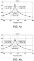
- the abscissa of the diagrams figs. 4a and 4b show the RF frequency in MHz at which the simulation was performed, whereas the ordinates of figs. 4a and 4b illustrate a logarithmic scale of the voltage measured at points 316 in fig. 3 divided by the voltage induced at point 310.
- the graphs in figs. 4a and 4b illustrate the electronic load at the RF receiver coil 300.
- Another advantage of this method is to have a coil testing arrangement as 'universal' phantom applicable for MR system tests independent on used magnetic field strength and types of RF coils.
Landscapes
- Physics & Mathematics (AREA)
- Condensed Matter Physics & Semiconductors (AREA)
- General Physics & Mathematics (AREA)
- High Energy & Nuclear Physics (AREA)
- Magnetic Resonance Imaging Apparatus (AREA)
Claims (14)
- Magnetresonanzspulen-Testanordnung (150), umfassend eine Kombination eines Phantoms (154) und einer elektrischen Schaltung (152; 302) zum Bereitstellen einer elektrischen Last für eine HF-Spule, wobei das Phantom (154) ein Behälter von bestimmter Größe und Form ist, der mit einem Material gefüllt ist, das das Vorhandensein von menschlichem Gewebe simuliert, wobei
die elektrische Schaltung ein räumliches Netzwerk von aktiven und/oder passiven elektrischen Komponenten umfasst, wobei die Kombination so angeordnet ist, dass sie im Sichtfeld der HF-Spule positioniert ist und die elektrische Schaltung (152; 302) zum Induzieren der elektrischen Last an der HF-Spule so ausgelegt ist, dass die elektrische Last einer elektrischen Last von organischem Gewebe bei der Magnetresonanzfrequenz der HF-Spule entspricht. - Anordnung (150) nach Anspruch 1, wobei die Anordnung zum Empfang in einem von der HF-Spule (128) umschriebenen Volumen (156) angepasst ist.
- Anordnung (150) nach Anspruch 1 oder 2, wobei das Netzwerk auf einer Leiterplatte, insbesondere einer mehrschichtigen Leiterplatte, ausgebildet ist.
- Anordnung (150) nach Anspruch 1, wobei die elektrische Schaltung (152; 302) nur passive elektrische Komponenten umfasst.
- Anordnung (150) nach Anspruch 1, wobei die elektrische Schaltung (152; 302) eine aktive elektrische Komponente umfasst, die zum Variieren der an die HF-Spule induzierten elektrischen Last angepasst ist.
- Anordnung (150) nach Anspruch 5, wobei die aktive elektrische Komponente eine Diode umfasst, wobei die aktive elektrische Komponente (200) eine Schaltung umfasst, die zum Schalten der Diode zum Blockieren eines Stromflusses durch die Diode angepasst ist, wobei das elektrische Schaltungsnetzwerk zum Schalten der Diode angepasst ist, falls die Magnetresonanzmaschine eine Magnetresonanz innerhalb des von der HF-Spule umschriebenen Volumens (156) anregt.
- Anordnung (150) nach einem der vorhergehenden Ansprüche, wobei die elektrische Schaltung (152; 302) Befestigungspunkte (206) zum Befestigen der elektrischen Schaltung (152; 302) an der HF-Spule und/oder dem Phantom (154) und/oder dem Patiententisch und/oder dem MR-System umfasst.
- Anordnung (150) nach Anspruch 1, wobei die elektrische Schaltung (152; 302) ferner eine Hochfrequenzübertragungsspule (204) umfasst.
- HF-Spule (128), umfassend eine Spulenprüfanordnung, wie in einem der vorhergehenden Ansprüche beansprucht.
- Verfahren zum Testen eines Magnetresonanzsystems, wobei das System eine HF-Spule (128) umfasst, wobei das Verfahren umfasst:- Bereitstellen einer HF-Spulentestanordnung (150), die eine Kombination eines Phantoms (154) und einer elektrische Schaltung (152; 302) umfasst, wobei das Phantom ein Behälter von bestimmter Größe und Form ist, der mit einem Material gefüllt ist, das die Anwesenheit von menschlichem Gewebe simuliert, wobei die elektrische Schaltung (152; 302) ein räumliches Netzwerk von aktiven und/oder passiven elektrischen Komponenten umfasst;- Positionieren der Kombination im Sichtfeld der HF-Spule, und die elektrische Schaltung (152; 302) zur Bereitstellung einer elektrischen Last für die HF-Spule (128) so angepasst ist, dass die elektrische Last einer durch organisches Gewebe induzierte elektrische Last bei der Magnetresonanzfrequenz der HF-Spule entspricht,- Testen des Magnetresonanzsystems, wobei die HF-Spule mit der HF-Spulen-Testanordnung (150) belastet ist.
- Verfahren nach Anspruch 10, wobei das Phantom (154) zur Verwendung mit einer Magnetresonanzmaschine geeignet ist.
- Verfahren nach Anspruch 10, wobei die elektrische Schaltung (152; 302) eine aktive elektrische Komponente umfasst, wobei das Verfahren ferner das Variieren der an die HF-Spule induzierten elektrischen Last durch die aktive elektrische Komponente umfasst.
- Verfahren nach einem der vorhergehenden Ansprüche 10 bis 12, wobei die elektrische Schaltung (152; 302) mechanische Fixierungspunkte (206) umfasst, wobei das Positionieren der Spulentestanordnung (150) ferner das Befestigen der elektrische Schaltung (152; 302) an dem Phantom (154) und/oder der HF-Spule (128) und/oder dem Patiententisch und/oder dem MR-System umfasst.
- Verfahren nach Anspruch 10, wobei die elektrische Schaltung (152; 302) ferner eine Hochfrequenzübertragungsspule (204) umfasst, wobei das Verfahren ferner das Senden eines Hochfrequenzsignals an die HF-Spule durch die Hochfrequenzübertragungsspule umfasst.
Priority Applications (1)
| Application Number | Priority Date | Filing Date | Title |
|---|---|---|---|
| EP09766242.3A EP2291671B1 (de) | 2008-06-20 | 2009-06-10 | Elektronische lastensimulationsvorrichtung zum testen von hf-spulen |
Applications Claiming Priority (3)
| Application Number | Priority Date | Filing Date | Title |
|---|---|---|---|
| EP08158695 | 2008-06-20 | ||
| EP09766242.3A EP2291671B1 (de) | 2008-06-20 | 2009-06-10 | Elektronische lastensimulationsvorrichtung zum testen von hf-spulen |
| PCT/IB2009/052458 WO2009153705A1 (en) | 2008-06-20 | 2009-06-10 | Electronic load simulator device for testing rf coils |
Publications (2)
| Publication Number | Publication Date |
|---|---|
| EP2291671A1 EP2291671A1 (de) | 2011-03-09 |
| EP2291671B1 true EP2291671B1 (de) | 2020-05-13 |
Family
ID=41066432
Family Applications (1)
| Application Number | Title | Priority Date | Filing Date |
|---|---|---|---|
| EP09766242.3A Active EP2291671B1 (de) | 2008-06-20 | 2009-06-10 | Elektronische lastensimulationsvorrichtung zum testen von hf-spulen |
Country Status (4)
| Country | Link |
|---|---|
| US (1) | US8633706B2 (de) |
| EP (1) | EP2291671B1 (de) |
| CN (1) | CN102066966B (de) |
| WO (1) | WO2009153705A1 (de) |
Families Citing this family (7)
| Publication number | Priority date | Publication date | Assignee | Title |
|---|---|---|---|---|
| CN101877546B (zh) * | 2010-06-18 | 2012-05-23 | 重庆大学 | 一种单相桥式整流型负载等效电路参数提取的统一方法 |
| US9201127B2 (en) * | 2010-11-26 | 2015-12-01 | General Electric Company | Apparatus for automatically testing and tuning radio frequency coil |
| CN106154196B (zh) * | 2015-03-31 | 2021-06-22 | 西门子(深圳)磁共振有限公司 | 磁共振成像系统的体线圈的检测方法和设备 |
| US10594664B2 (en) | 2017-03-13 | 2020-03-17 | At&T Intellectual Property I, L.P. | Extracting data from encrypted packet flows |
| JP6779394B2 (ja) * | 2018-01-15 | 2020-11-04 | 株式会社エム・アール・テクノロジー | Mri装置用電子ファントム及びその制御方法 |
| EP3570059B1 (de) * | 2018-05-16 | 2024-06-26 | Siemens Healthineers AG | Verfahren und mrt-vorrichtung zur qualitätsanalyse einer rf-spule |
| DE102020201104A1 (de) | 2020-01-30 | 2021-08-05 | Siemens Healthcare Gmbh | Elektronisches Phantom für Magnetresonanzvorrichtungen |
Family Cites Families (12)
| Publication number | Priority date | Publication date | Assignee | Title |
|---|---|---|---|---|
| DE69316467T2 (de) * | 1992-06-22 | 1998-07-30 | Koninkl Philips Electronics Nv | Phantom zum Simulieren der elektrischen Belastung in einem magnetischen Resonanzapparat |
| EP0579300B1 (de) * | 1992-06-22 | 1998-01-21 | Koninklijke Philips Electronics N.V. | Phantom zum Simulieren der elektrischen Belastung in einem magnetischen Resonanzapparat |
| US5387868A (en) * | 1992-09-29 | 1995-02-07 | U.S. Philips Corporation | Magnetic resonance apparatus |
| EP0590712B1 (de) | 1992-09-29 | 1997-08-20 | Koninklijke Philips Electronics N.V. | Kernspinresonanzgerät |
| US6861840B2 (en) | 2001-07-20 | 2005-03-01 | Mclean Hospital Corporation | Generation of synthetic nuclear magnetic resonance signals |
| US6867591B2 (en) | 2002-12-20 | 2005-03-15 | Medi-Physics, Inc. | NMR transfer standard |
| EP1595159A1 (de) * | 2003-02-03 | 2005-11-16 | Koninklijke Philips Electronics N.V. | Präzisionsgradientenverstärker mit mehreren ausgangsspannungspegeln |
| US7081752B2 (en) | 2003-04-04 | 2006-07-25 | General Electric Company | System and method of electrically loading radio-frequency coils using conductive polymers |
| US7215122B2 (en) | 2003-10-03 | 2007-05-08 | Invivo Corporation | Phantom for production of controllable fMRI signal |
| US7615999B2 (en) * | 2005-04-29 | 2009-11-10 | Koninklijke Philips Electronics N.V. | Method and circuit arrangement for operating multi-channel transmit/receive antenna devices |
| WO2007124320A2 (en) | 2006-04-19 | 2007-11-01 | University Of Florida Research Foundation, Inc. | Calibration of functional mri of living tissue involving a bold or boss contrast simulation phantom |
| JP2009544432A (ja) | 2006-07-28 | 2009-12-17 | コーニンクレッカ フィリップス エレクトロニクス エヌ ヴィ | Mriファントムにおいて誘電共振効果を減少するミセル溶液 |
-
2009
- 2009-06-10 CN CN200980123058.2A patent/CN102066966B/zh active Active
- 2009-06-10 EP EP09766242.3A patent/EP2291671B1/de active Active
- 2009-06-10 WO PCT/IB2009/052458 patent/WO2009153705A1/en not_active Ceased
- 2009-06-10 US US12/997,005 patent/US8633706B2/en active Active
Non-Patent Citations (1)
| Title |
|---|
| None * |
Also Published As
| Publication number | Publication date |
|---|---|
| US8633706B2 (en) | 2014-01-21 |
| WO2009153705A1 (en) | 2009-12-23 |
| CN102066966A (zh) | 2011-05-18 |
| EP2291671A1 (de) | 2011-03-09 |
| US20110163757A1 (en) | 2011-07-07 |
| CN102066966B (zh) | 2016-12-21 |
Similar Documents
| Publication | Publication Date | Title |
|---|---|---|
| Shchelokova et al. | Volumetric wireless coil based on periodically coupled split‐loop resonators for clinical wrist imaging | |
| Alecci et al. | Radio frequency magnetic field mapping of a 3 Tesla birdcage coil: experimental and theoretical dependence on sample properties | |
| EP2291671B1 (de) | Elektronische lastensimulationsvorrichtung zum testen von hf-spulen | |
| Vaughan et al. | Detunable transverse electromagnetic (TEM) volume coil for high‐field NMR | |
| CN1735814B (zh) | 用于具有多个发送通道的mr设备的高频系统及其中的mr设备 | |
| US7683623B2 (en) | RF volume coil with selectable field of view | |
| Williams et al. | A nested eight-channel transmit array with open-face concept for human brain imaging at 7 tesla | |
| JP2015039635A (ja) | 種々の形式のシムコイルを使用する磁気共鳴トモグラフィシステムの特に患者に適応した静磁場均一化方法 | |
| US7550973B2 (en) | Magnetic resonance apparatus, method and auxilliary coil element for manipulation of the B1 field | |
| JP2003180655A (ja) | Mr装置中の対象の位置を測定する方法、並びに、かかる方法を行うためのカテーテル及びmr装置 | |
| US10551466B2 (en) | Correction of a magnetic resonance transmission signal | |
| Keong Li et al. | Focused, eight‐element transceive phased array coil for parallel magnetic resonance imaging of the chest—theoretical considerations | |
| Giovannetti et al. | Design and simulation of a Helmholtz coil for magnetic resonance imaging and spectroscopy experiments with a 3T MR clinical scanner | |
| US7701211B2 (en) | Magnetic resonance imaging system and method | |
| Cheng et al. | Ultra-high field birdcage coils: A comparison study at 14.1 T | |
| Shajan et al. | Rat brain MRI at 16.4 T using a capacitively tunable patch antenna in combination with a receive array | |
| Buchanan et al. | Tabletop 700 MH z electron paramagnetic resonance imaging spectrometer | |
| Lopez Rios et al. | Design and construction of an optimized transmit/receive hybrid birdcage resonator to improve full body images of medium-sized animals in 7T scanner | |
| Horneff et al. | An EM simulation-based design flow for custom-built MR coils incorporating signal and noise | |
| JP2002529175A (ja) | Mriの勾配電磁界歪みの自動測定 | |
| JP2004305745A (ja) | 導電性ポリマーを用いて無線周波数コイルに電気的負荷を与えるためのシステム及び方法 | |
| Hartwig et al. | Decoupling and shielding numerical optimization of MRI phased-array coils | |
| Merkle et al. | Transmit B1‐field correction at 7T using actively tuned coupled inner elements | |
| Giovannetti et al. | Capacitors quality effect in magnetic resonance radiofrequency coils | |
| Fedotov et al. | A concept of volume wireless receive-only coil for 1.5 T MRI |
Legal Events
| Date | Code | Title | Description |
|---|---|---|---|
| PUAI | Public reference made under article 153(3) epc to a published international application that has entered the european phase |
Free format text: ORIGINAL CODE: 0009012 |
|
| 17P | Request for examination filed |
Effective date: 20110120 |
|
| AK | Designated contracting states |
Kind code of ref document: A1 Designated state(s): AT BE BG CH CY CZ DE DK EE ES FI FR GB GR HR HU IE IS IT LI LT LU LV MC MK MT NL NO PL PT RO SE SI SK TR |
|
| AX | Request for extension of the european patent |
Extension state: AL BA RS |
|
| DAX | Request for extension of the european patent (deleted) | ||
| RAP1 | Party data changed (applicant data changed or rights of an application transferred) |
Owner name: KONINKLIJKE PHILIPS N.V. |
|
| 17Q | First examination report despatched |
Effective date: 20160318 |
|
| STAA | Information on the status of an ep patent application or granted ep patent |
Free format text: STATUS: EXAMINATION IS IN PROGRESS |
|
| REG | Reference to a national code |
Ref country code: DE Ref legal event code: R079 Ref document number: 602009062042 Country of ref document: DE Free format text: PREVIOUS MAIN CLASS: G01R0033360000 Ipc: G01R0033580000 |
|
| GRAP | Despatch of communication of intention to grant a patent |
Free format text: ORIGINAL CODE: EPIDOSNIGR1 |
|
| STAA | Information on the status of an ep patent application or granted ep patent |
Free format text: STATUS: GRANT OF PATENT IS INTENDED |
|
| RIC1 | Information provided on ipc code assigned before grant |
Ipc: G01R 33/58 20060101AFI20191108BHEP Ipc: G01R 33/36 20060101ALI20191108BHEP |
|
| INTG | Intention to grant announced |
Effective date: 20191204 |
|
| RAP1 | Party data changed (applicant data changed or rights of an application transferred) |
Owner name: KONINKLIJKE PHILIPS N.V. |
|
| GRAS | Grant fee paid |
Free format text: ORIGINAL CODE: EPIDOSNIGR3 |
|
| GRAA | (expected) grant |
Free format text: ORIGINAL CODE: 0009210 |
|
| STAA | Information on the status of an ep patent application or granted ep patent |
Free format text: STATUS: THE PATENT HAS BEEN GRANTED |
|
| AK | Designated contracting states |
Kind code of ref document: B1 Designated state(s): AT BE BG CH CY CZ DE DK EE ES FI FR GB GR HR HU IE IS IT LI LT LU LV MC MK MT NL NO PL PT RO SE SI SK TR |
|
| REG | Reference to a national code |
Ref country code: GB Ref legal event code: FG4D |
|
| REG | Reference to a national code |
Ref country code: CH Ref legal event code: EP |
|
| REG | Reference to a national code |
Ref country code: DE Ref legal event code: R096 Ref document number: 602009062042 Country of ref document: DE |
|
| REG | Reference to a national code |
Ref country code: AT Ref legal event code: REF Ref document number: 1270994 Country of ref document: AT Kind code of ref document: T Effective date: 20200615 |
|
| REG | Reference to a national code |
Ref country code: DE Ref legal event code: R084 Ref document number: 602009062042 Country of ref document: DE |
|
| REG | Reference to a national code |
Ref country code: LT Ref legal event code: MG4D |
|
| REG | Reference to a national code |
Ref country code: NL Ref legal event code: MP Effective date: 20200513 |
|
| PG25 | Lapsed in a contracting state [announced via postgrant information from national office to epo] |
Ref country code: LT Free format text: LAPSE BECAUSE OF FAILURE TO SUBMIT A TRANSLATION OF THE DESCRIPTION OR TO PAY THE FEE WITHIN THE PRESCRIBED TIME-LIMIT Effective date: 20200513 Ref country code: GR Free format text: LAPSE BECAUSE OF FAILURE TO SUBMIT A TRANSLATION OF THE DESCRIPTION OR TO PAY THE FEE WITHIN THE PRESCRIBED TIME-LIMIT Effective date: 20200814 Ref country code: IS Free format text: LAPSE BECAUSE OF FAILURE TO SUBMIT A TRANSLATION OF THE DESCRIPTION OR TO PAY THE FEE WITHIN THE PRESCRIBED TIME-LIMIT Effective date: 20200913 Ref country code: PT Free format text: LAPSE BECAUSE OF FAILURE TO SUBMIT A TRANSLATION OF THE DESCRIPTION OR TO PAY THE FEE WITHIN THE PRESCRIBED TIME-LIMIT Effective date: 20200914 Ref country code: FI Free format text: LAPSE BECAUSE OF FAILURE TO SUBMIT A TRANSLATION OF THE DESCRIPTION OR TO PAY THE FEE WITHIN THE PRESCRIBED TIME-LIMIT Effective date: 20200513 Ref country code: NO Free format text: LAPSE BECAUSE OF FAILURE TO SUBMIT A TRANSLATION OF THE DESCRIPTION OR TO PAY THE FEE WITHIN THE PRESCRIBED TIME-LIMIT Effective date: 20200813 Ref country code: SE Free format text: LAPSE BECAUSE OF FAILURE TO SUBMIT A TRANSLATION OF THE DESCRIPTION OR TO PAY THE FEE WITHIN THE PRESCRIBED TIME-LIMIT Effective date: 20200513 |
|
| PG25 | Lapsed in a contracting state [announced via postgrant information from national office to epo] |
Ref country code: BG Free format text: LAPSE BECAUSE OF FAILURE TO SUBMIT A TRANSLATION OF THE DESCRIPTION OR TO PAY THE FEE WITHIN THE PRESCRIBED TIME-LIMIT Effective date: 20200813 Ref country code: LV Free format text: LAPSE BECAUSE OF FAILURE TO SUBMIT A TRANSLATION OF THE DESCRIPTION OR TO PAY THE FEE WITHIN THE PRESCRIBED TIME-LIMIT Effective date: 20200513 Ref country code: HR Free format text: LAPSE BECAUSE OF FAILURE TO SUBMIT A TRANSLATION OF THE DESCRIPTION OR TO PAY THE FEE WITHIN THE PRESCRIBED TIME-LIMIT Effective date: 20200513 |
|
| REG | Reference to a national code |
Ref country code: AT Ref legal event code: MK05 Ref document number: 1270994 Country of ref document: AT Kind code of ref document: T Effective date: 20200513 |
|
| REG | Reference to a national code |
Ref country code: GB Ref legal event code: 746 Effective date: 20201130 |
|
| PG25 | Lapsed in a contracting state [announced via postgrant information from national office to epo] |
Ref country code: NL Free format text: LAPSE BECAUSE OF FAILURE TO SUBMIT A TRANSLATION OF THE DESCRIPTION OR TO PAY THE FEE WITHIN THE PRESCRIBED TIME-LIMIT Effective date: 20200513 |
|
| PG25 | Lapsed in a contracting state [announced via postgrant information from national office to epo] |
Ref country code: ES Free format text: LAPSE BECAUSE OF FAILURE TO SUBMIT A TRANSLATION OF THE DESCRIPTION OR TO PAY THE FEE WITHIN THE PRESCRIBED TIME-LIMIT Effective date: 20200513 Ref country code: DK Free format text: LAPSE BECAUSE OF FAILURE TO SUBMIT A TRANSLATION OF THE DESCRIPTION OR TO PAY THE FEE WITHIN THE PRESCRIBED TIME-LIMIT Effective date: 20200513 Ref country code: IT Free format text: LAPSE BECAUSE OF FAILURE TO SUBMIT A TRANSLATION OF THE DESCRIPTION OR TO PAY THE FEE WITHIN THE PRESCRIBED TIME-LIMIT Effective date: 20200513 Ref country code: EE Free format text: LAPSE BECAUSE OF FAILURE TO SUBMIT A TRANSLATION OF THE DESCRIPTION OR TO PAY THE FEE WITHIN THE PRESCRIBED TIME-LIMIT Effective date: 20200513 Ref country code: AT Free format text: LAPSE BECAUSE OF FAILURE TO SUBMIT A TRANSLATION OF THE DESCRIPTION OR TO PAY THE FEE WITHIN THE PRESCRIBED TIME-LIMIT Effective date: 20200513 Ref country code: RO Free format text: LAPSE BECAUSE OF FAILURE TO SUBMIT A TRANSLATION OF THE DESCRIPTION OR TO PAY THE FEE WITHIN THE PRESCRIBED TIME-LIMIT Effective date: 20200513 Ref country code: CZ Free format text: LAPSE BECAUSE OF FAILURE TO SUBMIT A TRANSLATION OF THE DESCRIPTION OR TO PAY THE FEE WITHIN THE PRESCRIBED TIME-LIMIT Effective date: 20200513 |
|
| REG | Reference to a national code |
Ref country code: CH Ref legal event code: PL |
|
| REG | Reference to a national code |
Ref country code: DE Ref legal event code: R097 Ref document number: 602009062042 Country of ref document: DE |
|
| PG25 | Lapsed in a contracting state [announced via postgrant information from national office to epo] |
Ref country code: MC Free format text: LAPSE BECAUSE OF FAILURE TO SUBMIT A TRANSLATION OF THE DESCRIPTION OR TO PAY THE FEE WITHIN THE PRESCRIBED TIME-LIMIT Effective date: 20200513 Ref country code: PL Free format text: LAPSE BECAUSE OF FAILURE TO SUBMIT A TRANSLATION OF THE DESCRIPTION OR TO PAY THE FEE WITHIN THE PRESCRIBED TIME-LIMIT Effective date: 20200513 Ref country code: SK Free format text: LAPSE BECAUSE OF FAILURE TO SUBMIT A TRANSLATION OF THE DESCRIPTION OR TO PAY THE FEE WITHIN THE PRESCRIBED TIME-LIMIT Effective date: 20200513 |
|
| PLBE | No opposition filed within time limit |
Free format text: ORIGINAL CODE: 0009261 |
|
| STAA | Information on the status of an ep patent application or granted ep patent |
Free format text: STATUS: NO OPPOSITION FILED WITHIN TIME LIMIT |
|
| PG25 | Lapsed in a contracting state [announced via postgrant information from national office to epo] |
Ref country code: LU Free format text: LAPSE BECAUSE OF NON-PAYMENT OF DUE FEES Effective date: 20200610 |
|
| REG | Reference to a national code |
Ref country code: BE Ref legal event code: MM Effective date: 20200630 |
|
| 26N | No opposition filed |
Effective date: 20210216 |
|
| PG25 | Lapsed in a contracting state [announced via postgrant information from national office to epo] |
Ref country code: LI Free format text: LAPSE BECAUSE OF NON-PAYMENT OF DUE FEES Effective date: 20200630 Ref country code: IE Free format text: LAPSE BECAUSE OF NON-PAYMENT OF DUE FEES Effective date: 20200610 Ref country code: CH Free format text: LAPSE BECAUSE OF NON-PAYMENT OF DUE FEES Effective date: 20200630 |
|
| PG25 | Lapsed in a contracting state [announced via postgrant information from national office to epo] |
Ref country code: SI Free format text: LAPSE BECAUSE OF FAILURE TO SUBMIT A TRANSLATION OF THE DESCRIPTION OR TO PAY THE FEE WITHIN THE PRESCRIBED TIME-LIMIT Effective date: 20200513 Ref country code: BE Free format text: LAPSE BECAUSE OF NON-PAYMENT OF DUE FEES Effective date: 20200630 |
|
| PG25 | Lapsed in a contracting state [announced via postgrant information from national office to epo] |
Ref country code: TR Free format text: LAPSE BECAUSE OF FAILURE TO SUBMIT A TRANSLATION OF THE DESCRIPTION OR TO PAY THE FEE WITHIN THE PRESCRIBED TIME-LIMIT Effective date: 20200513 Ref country code: MT Free format text: LAPSE BECAUSE OF FAILURE TO SUBMIT A TRANSLATION OF THE DESCRIPTION OR TO PAY THE FEE WITHIN THE PRESCRIBED TIME-LIMIT Effective date: 20200513 Ref country code: CY Free format text: LAPSE BECAUSE OF FAILURE TO SUBMIT A TRANSLATION OF THE DESCRIPTION OR TO PAY THE FEE WITHIN THE PRESCRIBED TIME-LIMIT Effective date: 20200513 |
|
| PG25 | Lapsed in a contracting state [announced via postgrant information from national office to epo] |
Ref country code: MK Free format text: LAPSE BECAUSE OF FAILURE TO SUBMIT A TRANSLATION OF THE DESCRIPTION OR TO PAY THE FEE WITHIN THE PRESCRIBED TIME-LIMIT Effective date: 20200513 |
|
| PGFP | Annual fee paid to national office [announced via postgrant information from national office to epo] |
Ref country code: DE Payment date: 20250626 Year of fee payment: 17 |
|
| PGFP | Annual fee paid to national office [announced via postgrant information from national office to epo] |
Ref country code: GB Payment date: 20250617 Year of fee payment: 17 |
|
| PGFP | Annual fee paid to national office [announced via postgrant information from national office to epo] |
Ref country code: FR Payment date: 20250624 Year of fee payment: 17 |