EP2291879B1 - Festoxidbrennstoffzellensysteme mit wärmetauschern - Google Patents
Festoxidbrennstoffzellensysteme mit wärmetauschern Download PDFInfo
- Publication number
- EP2291879B1 EP2291879B1 EP09758674A EP09758674A EP2291879B1 EP 2291879 B1 EP2291879 B1 EP 2291879B1 EP 09758674 A EP09758674 A EP 09758674A EP 09758674 A EP09758674 A EP 09758674A EP 2291879 B1 EP2291879 B1 EP 2291879B1
- Authority
- EP
- European Patent Office
- Prior art keywords
- modular
- fuel cell
- heat exchange
- oxidant
- packet
- Prior art date
- Legal status (The legal status is an assumption and is not a legal conclusion. Google has not performed a legal analysis and makes no representation as to the accuracy of the status listed.)
- Not-in-force
Links
- 239000000446 fuel Substances 0.000 title claims abstract 39
- 239000007787 solid Substances 0.000 title claims abstract 10
- 239000003792 electrolyte Substances 0.000 claims abstract 18
- 238000000034 method Methods 0.000 claims abstract 13
- 230000000712 assembly Effects 0.000 claims abstract 5
- 238000000429 assembly Methods 0.000 claims abstract 5
- 239000007800 oxidant agent Substances 0.000 claims 29
- 230000001590 oxidative effect Effects 0.000 claims 29
- 239000012530 fluid Substances 0.000 claims 3
- 238000003487 electrochemical reaction Methods 0.000 claims 2
- UFHFLCQGNIYNRP-UHFFFAOYSA-N Hydrogen Chemical compound [H][H] UFHFLCQGNIYNRP-UHFFFAOYSA-N 0.000 claims 1
- QVGXLLKOCUKJST-UHFFFAOYSA-N atomic oxygen Chemical compound [O] QVGXLLKOCUKJST-UHFFFAOYSA-N 0.000 claims 1
- 239000002184 metal Substances 0.000 claims 1
- 239000001301 oxygen Substances 0.000 claims 1
- 229910052760 oxygen Inorganic materials 0.000 claims 1
- 230000004888 barrier function Effects 0.000 abstract 1
Images

Classifications
-
- H—ELECTRICITY
- H01—ELECTRIC ELEMENTS
- H01M—PROCESSES OR MEANS, e.g. BATTERIES, FOR THE DIRECT CONVERSION OF CHEMICAL ENERGY INTO ELECTRICAL ENERGY
- H01M8/00—Fuel cells; Manufacture thereof
- H01M8/02—Details
- H01M8/0271—Sealing or supporting means around electrodes, matrices or membranes
- H01M8/0273—Sealing or supporting means around electrodes, matrices or membranes with sealing or supporting means in the form of a frame
-
- H—ELECTRICITY
- H01—ELECTRIC ELEMENTS
- H01M—PROCESSES OR MEANS, e.g. BATTERIES, FOR THE DIRECT CONVERSION OF CHEMICAL ENERGY INTO ELECTRICAL ENERGY
- H01M8/00—Fuel cells; Manufacture thereof
- H01M8/04—Auxiliary arrangements, e.g. for control of pressure or for circulation of fluids
- H01M8/04007—Auxiliary arrangements, e.g. for control of pressure or for circulation of fluids related to heat exchange
- H01M8/04014—Heat exchange using gaseous fluids; Heat exchange by combustion of reactants
-
- H—ELECTRICITY
- H01—ELECTRIC ELEMENTS
- H01M—PROCESSES OR MEANS, e.g. BATTERIES, FOR THE DIRECT CONVERSION OF CHEMICAL ENERGY INTO ELECTRICAL ENERGY
- H01M8/00—Fuel cells; Manufacture thereof
- H01M8/04—Auxiliary arrangements, e.g. for control of pressure or for circulation of fluids
- H01M8/04007—Auxiliary arrangements, e.g. for control of pressure or for circulation of fluids related to heat exchange
- H01M8/04067—Heat exchange or temperature measuring elements, thermal insulation, e.g. heat pipes, heat pumps, fins
- H01M8/04074—Heat exchange unit structures specially adapted for fuel cell
-
- H—ELECTRICITY
- H01—ELECTRIC ELEMENTS
- H01M—PROCESSES OR MEANS, e.g. BATTERIES, FOR THE DIRECT CONVERSION OF CHEMICAL ENERGY INTO ELECTRICAL ENERGY
- H01M8/00—Fuel cells; Manufacture thereof
- H01M8/04—Auxiliary arrangements, e.g. for control of pressure or for circulation of fluids
- H01M8/04223—Auxiliary arrangements, e.g. for control of pressure or for circulation of fluids during start-up or shut-down; Depolarisation or activation, e.g. purging; Means for short-circuiting defective fuel cells
- H01M8/04268—Heating of fuel cells during the start-up of the fuel cells
-
- H—ELECTRICITY
- H01—ELECTRIC ELEMENTS
- H01M—PROCESSES OR MEANS, e.g. BATTERIES, FOR THE DIRECT CONVERSION OF CHEMICAL ENERGY INTO ELECTRICAL ENERGY
- H01M8/00—Fuel cells; Manufacture thereof
- H01M8/24—Grouping of fuel cells, e.g. stacking of fuel cells
- H01M8/241—Grouping of fuel cells, e.g. stacking of fuel cells with solid or matrix-supported electrolytes
- H01M8/2425—High-temperature cells with solid electrolytes
- H01M8/2432—Grouping of unit cells of planar configuration
-
- H—ELECTRICITY
- H01—ELECTRIC ELEMENTS
- H01M—PROCESSES OR MEANS, e.g. BATTERIES, FOR THE DIRECT CONVERSION OF CHEMICAL ENERGY INTO ELECTRICAL ENERGY
- H01M8/00—Fuel cells; Manufacture thereof
- H01M8/24—Grouping of fuel cells, e.g. stacking of fuel cells
- H01M8/2465—Details of groupings of fuel cells
- H01M8/247—Arrangements for tightening a stack, for accommodation of a stack in a tank or for assembling different tanks
- H01M8/2475—Enclosures, casings or containers of fuel cell stacks
-
- H—ELECTRICITY
- H01—ELECTRIC ELEMENTS
- H01M—PROCESSES OR MEANS, e.g. BATTERIES, FOR THE DIRECT CONVERSION OF CHEMICAL ENERGY INTO ELECTRICAL ENERGY
- H01M8/00—Fuel cells; Manufacture thereof
- H01M8/10—Fuel cells with solid electrolytes
- H01M8/12—Fuel cells with solid electrolytes operating at high temperature, e.g. with stabilised ZrO2 electrolyte
- H01M2008/1293—Fuel cells with solid oxide electrolytes
-
- Y—GENERAL TAGGING OF NEW TECHNOLOGICAL DEVELOPMENTS; GENERAL TAGGING OF CROSS-SECTIONAL TECHNOLOGIES SPANNING OVER SEVERAL SECTIONS OF THE IPC; TECHNICAL SUBJECTS COVERED BY FORMER USPC CROSS-REFERENCE ART COLLECTIONS [XRACs] AND DIGESTS
- Y02—TECHNOLOGIES OR APPLICATIONS FOR MITIGATION OR ADAPTATION AGAINST CLIMATE CHANGE
- Y02E—REDUCTION OF GREENHOUSE GAS [GHG] EMISSIONS, RELATED TO ENERGY GENERATION, TRANSMISSION OR DISTRIBUTION
- Y02E60/00—Enabling technologies; Technologies with a potential or indirect contribution to GHG emissions mitigation
- Y02E60/30—Hydrogen technology
- Y02E60/50—Fuel cells
Definitions
- the present invention relates to solid oxide fuel cells and, more particularly, to systems and methods for managing the thermal energy produced by the electrochemical reactions within a reaction chamber.
- Solid oxide fuel cells are one type of fuel cell that work at very high temperatures, typically between 700 °C and 1000 °C.
- Solid oxide fuel cells can have multiple geometries, but are typically configured in a planar geometry.
- an electrolyte is sandwiched between a single anode electrode and a single cathode electrode.
- the sandwiched electrolyte is used as a partition between a fuel gas, such as hydrogen, which is supplied to a partition on the anode electrode side, and an air or oxygen gas, which is supplied to the partition on the cathode electrode side.
- a typical solid oxide fuel cell system approximately one half of the kinetic energy of reactants, such as fuel and oxygen, is converted into electricity and the other half is converted to thermal energy, which causes a significant temperature increase within the SOFC system.
- reactants In order to trigger fast electrochemical reactions, the reactants often must be heated to a high temperature.
- the reactants In order to trigger fast electrochemical reactions, the reactants often must be heated to a high temperature.
- the reactants In a system using a thin yttria-partially stabilized zirconia (3YSZ) electrolyte, the reactants have to be heated to approximately 725°C to obtain an effective reaction. With such an initial temperature of reactants, the peak temperature within the fuel cell for a stoichiometric hydrogen-air system can rise to more than 1000°C.
- U.S. 2004/0170879A1 discloses a shape memory alloy structure that is connected to a fuel cell for thermal management.
- U.S. 2005/0014046A1 discloses an internal bipolar heat exchanger that is used to remove the heat from an anode side of an individual cell to heat the cathode flow of another cell.
- a fluid heat exchanger is disclosed for transferring heat between fuel cell units and a heat exchanger fluid flow, which flows in a direction perpendicular to the electrolyte surface.
- a reformer reactor is disclosed that is connected to a fuel cell for helping the thermal management at the system level.
- an internal reformer is disclosed for use in thermal management of a fuel cell.
- the present invention relates to embodiments of stack designs for solid oxide fuel cell (SOFC) systems exhibiting high efficiency and a relatively narrow distribution of operating temperature across the electrolyte of the SOFC.
- SOFC solid oxide fuel cell
- a modular solid oxide fuel cell system comprises: (i) a housing; (ii) at least one modular fuel cell packet comprising:
- the SOFC systems comprise preheating chambers that are interposed between active SOFC packets, such as planar electrolyte electrode assemblies within SOFCs, to provide internal heat exchange, which reduces or eliminates the need for an inefficient external preheating system.
- active SOFC packets such as planar electrolyte electrode assemblies within SOFCs
- the overall system efficiency can be significantly increased.
- preheating the air allows for a reduced flow rate, which also increases the system efficiency and reliability.
- the preheating channels can also act as barriers between each single fuel cell packet, which aids in isolating damage within a single fuel cell device.
- the present invention provides a modular solid oxide fuel cell system comprising a housing, at least one modular fuel cell packet, and a plurality of modular oxidant heat exchange packets.
- the at least one modular fuel cell packet comprises a fuel cell frame, a first electrode assembly comprising a first planar electrolyte sheet having a plurality of anodes disposed on a first surface of the first electrolyte sheet and a plurality of cathodes disposed on an opposed second surface of the first electrolyte sheet, and a second electrode assembly comprising a second planar electrolyte sheet having a plurality of anodes disposed on a first surface of the second electrolyte sheet and a plurality of cathodes disposed on an opposed second surface of the second electrolyte sheet.
- the fuel cell frame can support the first and second electrode assemblies such that they are separated from one another and such that the respective first surfaces of the first and second electrolyte sheets face each other and define an anode chamber.
- the fuel cell frame can further define a fuel inlet in fluid communication with the anode chamber.
- the housing can support the at least one modular fuel cell packet and the plurality of modular heat exchange packets.
- the pair of modular heat exchange packets can be positioned in spaced opposition and define an oxidant chamber therebetween.
- a modular fuel cell packet can be positioned within the oxidant chamber in spaced relation to the pair of modular heat exchange packets.
- the outlet of the pair of modular heat exchange packets is in fluid communication with the oxidant chamber
- the present invention provides a method for generating electrical power that comprises providing a modular solid oxide fuel cell system comprising a housing, at least one modular fuel cell packet, and a plurality of modular oxidant heat exchange packets.
- the method can further comprise positioning at least two of the plurality of modular oxidant heat exchange packets within the housing in spaced relation to each other and positioning one of the at least one modular fuel cell packets within the housing and in between the at least two modular oxidant heat exchange packets.
- the at least one modular fuel cell packets is in spaced relation to each of the at least two modular oxidant heat exchange packets.
- the method comprises supplying an oxidant stream to the oxidant inlet of at least one of the modular oxidant heat exchange packets, and supplying a fuel stream to the fuel inlet of the at least one modular fuel cell packet.
- the method comprises using thermal energy generated by the at least one fuel cell packet to preheat the oxidant stream.
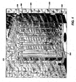
- FIG. 1 is a cut-away view of a modular solid oxide fuel cell system within an operating environment, according to one embodiment of the present invention.
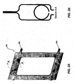
- FIG. 2A illustrates a fuel cell frame of a modular fuel cell packet, according to another embodiment of the present invention.
- FIG. 2B is a cross-sectional view of Section A-A of the fuel cell packet frame of FIG. 2A .
- FIG. 3 illustrates a modular fuel cell packet, according to one embodiment of the present invention.
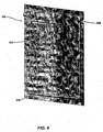
- FIG. 4 illustrates a side wall of a modular oxidant heat exchange packet, according to other embodiment of the present invention.
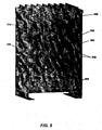
- FIG. 5 is a perspective, cross-sectional view of a modular solid oxide fuel cell system with modular oxidant heat exchange packets arranged therein, according to one exemplary embodiment of the present invention.
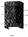
- FIG. 6 is a perspective, cross-sectional view of a modular solid oxide fuel cell system with modular fuel cell packets and modular heat exchange packets arranged therein, according to another exemplary embodiment of the present invention.
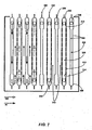
- FIG. 7 illustrates oxidant and fuel flow within a modular solid oxide fuel cell.
- Ranges can be expressed herein as from “about” one particular value, and/or to "about” another particular value. When such a range is expressed, another embodiment includes from the one particular value and/or to the other particular value. Similarly, when values are expressed as approximations, by use of the antecedent "about,” it will be understood that the particular value forms another embodiment. It will be further understood that the endpoints of each of the ranges are significant both in relation to the other endpoint, and independently of the other endpoint.
- the present invention provides systems and methods for managing temperature distribution within a modular solid oxide fuel cell device, and increasing overall system efficiency. These systems and methods can, in various embodiments, increase the efficiency of a solid oxide fuel cell system by utilizing thermal energy produced in reactions within the fuel cell device to preheat air and/or fuel gases entering the fuel cell device, thereby reducing and/or eliminating the need for an external preheating system.
- a modular solid oxide fuel cell system 10 comprises a housing 100, at least one modular fuel cell packet 200, and at least one modular oxidant heat exchange packet 300.
- a plurality of modular fuel cell packets 200 and a plurality of modular oxidant heat exchange packets 300 can be arranged within the housing 100 in an alternating array of fuel cell packets and oxidant heat exchange packets.
- the fuel cell packets and heat exchange packets can be arranged such that each fuel cell packet is positioned in between two heat exchange packets. Therefore, in this configuration, a minimum number of packets are 1 fuel cell packet, and 2 heat exchange packets. The maximum number of packets is determined by the amount of output power required from the solid oxide fuel cell system.
- Each fuel cell packet 200 incorporates a hermetically isolated fuel chamber situated inside the fuel cell packet that is formed between the two fuel cell devices (also referred to an electrode assemblies herein). More specifically, a fuel cell packet 200, according to various embodiments, can comprise a fuel cell packet frame 202 and at least one electrode assembly (i.e., a fuel cell device) 210.
- each fuel cell device 210 is a multi-cell device- i.e., each fuel cell device 210 comprises a plurality of arrayed fuel cells. In this particular embodiment, each fuel cell device is a planar, electrolyte supported fuel cell array.
- the fuel cell frame can be made of substantially rectangular stamped sheets of various materials.
- the fuel cell frame may be manufactured, for example, from stainless steel sheets 203, such as E-bright, or 446-stainless steel.
- a fuel cell frame may be made from glass, glass ceramic, fully or partially stabilized zirconia.
- the coefficients of thermal expansion (CTE) of the frame material is close to that of the or the electrolyte material.
- each frame can be manufactured as a sheet and can have a substantially rectangular aperture 202A defined therein the inner portion of the sheet; thus, each sheet can define an inner periphery and an outer periphery.
- the sheet can be stamped, for example, in the portion of the sheet lying between the inner periphery and outer periphery, such as to form a well.
- the well can be shaped such that when the sheets 203 are adjoined, face-to-face, they make substantially full contact along portions of the outer periphery, but are at a spaced distance from each other along portions of the inner periphery.
- a fuel inlet 204 can be in fluid communication with the well formed in the lower portion of the fuel cell frame, such as shown in Figure 2A .
- a fuel outlet 206 can be in fluid communication with the well formed in the upper portion of the fuel cell frame.
- a fuel cell packet 200 can comprise at least one fuel cell device 210 (also referred to as electrode assembly herein).
- an electrode assembly can comprise an electrolyte sheet 212 that can be a substantially planar sheet with a first surface and an opposing second surface.
- a plurality of anodes 214 can be disposed on the first surface and a plurality of cathodes 216 can be disposed on the opposed second surface, forming a multi-cell fuel cell device.
- a second electrode assembly can be similarly formed.
- the fuel cell frame 202 can support the first and second electrode assemblies 210 such that the first and second electrode assemblies (i.e., fuel cell devices) 210 are separated from one another at a spaced distance.
- the first and second electrode assemblies 210 are supported by the frame 202 such that the respective first surfaces of the first and second electrode assemblies 210 face each other and define an anode chamber 220 (i.e., fuel chamber).
- the fuel cell frame 202 can be formed of a stamped material (or, alternatively, can be made from glass or glass ceramic) in such a manner that portions of the sheets of the fuel cell frame are at a spaced distance d from each other along the inner periphery. This distance d made be, for example, 0.5 mm or more. A typical distance may be, for example 1 mm to 7mm.
- the direction of fuel flow in the fuel cell packets 200 is substantially in the direction of gravity.
- the frames 202 of fuel cell packets may be fabricated, for example, from formed stainless steel alloy with a wall thickness of no more than 1 mm, for example 0.25 mm -1 mm.
- the plurality of cathodes react 216 with an oxidant, such as oxygen-containing air, to produce oxygen ions.
- the plurality of anodes 214 use the oxygen ions produced by the cathode 216 to react with fuel (such as, but not limited to, hydrogen gas) to produce water and electricity.
- the electrolyte sheet 212 acts as a membrane or barrier, separating the oxidant on the cathode side from the fuel on the anode side. In this configuration, the electrolyte sheet 212 can also serve as an electrical insulator that prevents electrons resulting from the oxidation reaction on the anode side from reaching the cathode side.
- the electrolyte sheet 212 can be configured to conduct the oxygen ions, produced by the cathodes 216, to the anodes 214.
- a modular solid oxide fuel cell system further comprises a plurality of modular oxidant heat exchange packets 300.
- a modular oxidant heat exchange packet can comprise a body having a pair of opposed, spaced side walls 302 that are respectively positioned to define an interior volume 301 (i.e., air chamber), also referred to as a heat exchange cavity herein.
- Figure 4 illustrates a side wall 302 of an exemplary modular oxidant heat exchange packet 300.
- the walls 302 of the modular oxidant heat exchange packet may be manufactured, for example, from stainless steel such as E-bright, or 446 stainless steel, or a nickel alloy, or may be made from glass, glass ceramic, fully or partially stabilized zirconia.
- the walls 302 may be fabricated from formed stainless steel alloy with a thickness not greater than 1 mm.
- the walls 302 may be formed, for example, from formed stainless steel alloy with a wall thickness of no more than 1 mm, for example 0.1 mm to 1 mm.
- the walls 302 of the heat exchange packets 300 may comprise two formed alloy structures (walls) that abut each other, but not constrained such that each stamp/form can slip relative to each other under conditions of thermal gradients.
- a portion of the side walls can be formed to define an oxidant inlet 306 in communication with the interior volume (internal air chamber) 301, which serves as an oxidant preheating chamber (i.e., heat exchange chamber).
- the side walls 302 can further define at least one outlet 308 in communication with the interior volume 301.
- the outlet is a substantially horizontal slit defined in the lower portion of the side wall 302.
- the oxidant outlet 308 is similar in shape to the oxidant inlet 306.
- the heat exchange packets 300 do not need to be hermetically sealed, and do not need to be CTE matched to the fuel cell devices.
- the heat exchange packets 300 may be comprised of a frame and two planar electrolyte sheets, the electrolyte sheets being arranged substantially parallel to one another, such that the cavity between them defines a an internal air chamber 301 that serves as an oxidant *(air) heat exchange chamber.
- a plurality of modular oxidant heat exchange packets 300 can be supported by the housing 100.
- at least two heat exchange packets 300 can be positioned within the housing 100 in spaced opposition with each other, to define an oxidant chamber 310 therebetween.
- the modular oxidant heat exchange packets 300 are positioned substantially vertically within the housing, such as shown in Figure 5 .
- the housing 100 can similarly support at least one modular fuel cell packet, such as shown in Figures 6 and 7 .
- the at least one modular fuel cell packet 200 is positioned in between and in spaced relation to a pair of modular oxidant heat exchange packets 300 (e.g., within the oxidant chamber 310 ), thus forming cathode reaction chamber(s) 310A situated between the walls of the fuel cell packets 200 and the walls of the heat exchange packets 300. That is, the heat exchange packet 300 faces the cathode side(s) of the fuel cell devices 210 of the modular fuel cell packets 200.
- Spaces (wall to wall) between adjacent packets may be, for example, of about 0.5 mm to 7 mm, more preferably 1 mm to 5 mm.
- a modular solid oxide fuel cell device can comprise "n" fuel cell packets and "n + 1" modular oxidant heat exchange packets.
- a modular solid oxide fuel cell device can comprise one (1) modular fuel cell packets and two (2) modular oxidant heat exchange packets.
- "n” can be at least two (2), such that a modular solid oxide fuel cell device can comprise at least two (2) modular fuel cell packets and at least three (3) modular oxidant heat exchange packets.
- a modular solid oxide fuel cell can comprise any number of modular fuel cell packets and any number of modular oxidant heat exchange packets and is not intended to be limited to the specific numbers referred to herein.
- FIG 7 illustrates schematically the exemplary flow of an oxidant, such as air, and fuel within a modular solid oxide fuel cell system that utilizes heat exchange packets similar to that shown in Figure 4A.
- air enters the device via the oxidant inlet 306 of at least one of the modular oxidant heat exchange packets 300.
- the air flows downwardly (i.e., in direction of gravity) through the heat exchange packet (i.e., through the interior volume 301 formed therein) and exits the oxidant chamber via the outlet 308.
- the air then passes through the oxidant chamber 310 (and thus through the cathode reaction chamber 310A ) along the cathode side or surface of the modular fuel cell packet positioned next to the heat exchange packet.
- the air or oxidant reacts with the cathodes 216 to produce oxygen ions, which are conducted through the electrolyte sheet 212 to the anode side or surface.
- Fuel such as but not limited to hydrogen gas, enters the modular fuel cell packet 200, specifically into the anode chamber 220, via the fuel inlet 204.
- the fuel reacts with the oxygen ions at the anodes to form water and electricity.
- the products of this reaction (e.g., exhaust gas) exit the anode chamber via the outlet 206.
- the air passing through the interior volume 304 of the heat exchange packet can exit via the outlets 308 defined in each side wall 302 of the respective heat exchange packet.
- air can pass through the oxidant chamber 310 along the cathode side of each of the fuel cell packets 200 that faces the respective heat exchange packet 300.
- the walls of the fuel cell packet 200 and the walls of the adjacent respective heat exchange packets (oxidant heat exchange packets) 300 provide, in part, cathode reaction chambers 310A in which air flows between the walls of the fuel cell packet 200 and the walls of the adjacent respective heat exchange packets 300.
- the heat exchange packets 300 help control and/or minimize thermal gradients within the fuel cell packet(s) 200 and the fuel cell stack by transferring thermal energy generated by the fuel cell packet(s) 200 to cooler air within the heat exchange packets oxidant heat exchange packet(s) 300, for example by utilizing a radiant susceptor and spreader. That is, the walls of the heat exchange packets act as radient susceptors by radiant heat absorption, and then spread the heat and provide it to the oxidant inside the interior volume 301 of the heat exchange packets 300.
- the heat is:
- the air (or fuel in an alternate embodiment not described herein) is first preheated in by the heat release from the electrode assembly 210.
- the heat is first radiantly transferred from the fuel cell devices 210 or the side walls of the fuel packet(s) 200 to the alloy wall surface(s) of the heat exchange packet(s) 300, then is conductively spread throughout the walls of the heat exchange packet(s) 300, and finally transferred to the incoming air via convection and to a lesser extent gas phase conduction.
- the temperature gradient can be maintained within 50 °C, more preferably within 35 °C, and most preferably within 25 °C.
- the oxidant must be at a predetermined temperature in order to react with the cathodes, or in order to allow for a faster and/or more efficient electrochemical reaction with the cathodes.
- the fuel may also need to be at a predetermined temperature in order to react with the oxygen ions to produce the electricity.
- the predetermined temperature of the supplied fuel, air, or both can be any temperature greater than 600 °C, such as approximately 600 °C-1000 °C.
- the predetermined temperature of the fuel, air, or both can be in the range of from about 650 °C to about 900 °C, preferably 700 °C to about 900 °C, or 650 °C -800 °C.
- the air or oxidant that is initially provided to the modular fuel cell system can be preheated to a specific predetermined temperature.
- heat is generated along the electrolyte sheets 212 of the modular fuel cell packets 200 by the reaction of the fuel with the oxygen ions.
- the thermal energy produced can be conducted through the side walls of each of the modular heat exchange packets 300 to preheat the air passing therethrough.
- the modular heat exchange packets 300 can be comprised of a material having a predetermined thermal conductivity. Therefore, in one embodiment, the thermal energy that is produced by the reactions of the fuel cell packets can be used to preheat the oxidant, which is needed to produce the reactions.
- the oxidant can be preheated by an external preheating means in order to initially start the process.
- the modular solid oxide fuel cell system can be substantially self-sustaining without the need for external heating means for either the oxidant or the fuel or both.
- relatively cooler air can be brought into the fuel cell system via the inlets of the heat exchange packets 300, and this air can be progressively heated as it passes therethrough and can reach the necessary predetermined temperature by the time that the air passes along and reacts with the cathodes 216.
- each of the packets can expand at varying rates without interfering with the other packets.
- the modular heat exchange packets have walls that can comprise a material having a higher coefficient of thermal expansion (CTE) than that of the frame of the modular fuel cell packets, for instance.
- CTE coefficient of thermal expansion
- the modular heat exchange packets may experience larger thermal gradients than those experienced by the fuel cell packets, and thus can move independently of the fuel cell packets and avoid interfering therewith
Landscapes
- Engineering & Computer Science (AREA)
- Chemical & Material Sciences (AREA)
- Life Sciences & Earth Sciences (AREA)
- Manufacturing & Machinery (AREA)
- Sustainable Development (AREA)
- Sustainable Energy (AREA)
- Chemical Kinetics & Catalysis (AREA)
- Electrochemistry (AREA)
- General Chemical & Material Sciences (AREA)
- Combustion & Propulsion (AREA)
- Fuel Cell (AREA)
Claims (15)
- Modulares Festoxid-Brennstaffzellensystem, das Folgendes umfasst:ein Gehäuse;wenigstens ein modulares Brerinstoffzellenpaket, das Folgendes umfasst:einen Brennstoffzellenrahmen;eine erste Elektrodenbaugruppe, die ein erstes planares Elektrolytblech mit mehreren auf einer ersten Fläche des ersten Elektrolytblechs angeordneten Anoden und mehreren auf einer gegenüberliegenden zweiten Fläche des ersten Elektrolytblechs angeordneten Kathoden umfasst; undeine zweite Elektrodenbaugruppe, die ein zweites planares Elektrolytblech mit mehreren auf einer ersten Fläche des zweiten Elektrolytblechs angeordneten Anoden und mehreren auf einer gegenüberliegenden zweiten Fläche des zweiten Elektrolytblechs angeordneten Kathoden umfasst,wobei der Brennstoffzellenrahmen die erste und die zweite Elektrodenbaugruppe so trägt, dass die jeweilige erste und zweite Elektrodenbaugruppe voneinander getrennt sind, und so, dass die jeweilige erste Fläche der ersten und zweiten Elektrolytbleche jeweils einander zugewandt sind und eine Anodenkammer definieren, wobei der Brennstoffzellenrahmen ferner einen Brennstoffeinlass in Fluidverbindung mit der Anodenkammer definiert; undmehrere modulare Oxidationsmittel-Wärmetauscherpakete, wobei jedes Wärmetauscherpaket einen Körper mit einem Paar gegenüberliegender, beabstandeter Seitenwände umfasst, wobei der Körper ferner ein Innenvolumen, einen Oxidationsmitteleinlass in Verbindung mit dem Innenvolumen und wenigstens einen Auslass in Verbindung mit dem Innenvolumen definiert,wobei das Gehäuse das wenigstens eine modulare Brennstoffzellenpaket und die mehreren modularen Wärmetauscherpakete trägt, wobei ein Paar modularer Wärmetauscherpakete der mehreren modularen Wärmetauscherpakete in einer beabstandeten Gegenüberlage positioniert sind und eine Oxidationsmittelkammer dazwischen definieren, wobei ein modulares Brennstoffzellenpaket des wenigstens einen modularen Brennstoffzellenpakets in der Oxidationsmittelkammer in einer beabstandeten Beziehung zu dem Paar modularen Wärmetauscherpaketen positioniert ist; und wobei der Auslass des Paares von modularen Wärmetauscherpaketen in Fluidverbindung mit der Oxidationsmittelkammer ist.
- Modulares Festoxid-Brennstoffzellensystem nach Anspruch 1, das "n" Brennstoffzellenpakete und "n + 1" modulare Oxidationsmittel-Wärmetauscherpakete umfasst, wobei "n" wenigstens 2 ist.
- Modulares Festoxid-Brennstoffzellensystem nach Anspruch 1, wobei das Paar gegenüberliegender, beabstandeter Seitenwände in Strahlungswärmeverbindung mit Wärme ist, die von dem wenigstens einen modularen Brennstoffzellenpaket emittiert wird, und wobei das Paar gegenüberliegender, beabstandeter Seitenwände Oxidationsmittel vorheizt, das durch das Innenvolumen des Wärmetauscherpakets fließt.
- Modulares Festoxid-Brennstoffzellensystem nach Anspruch 1, wobei die mehreren modularen Wärmetauscherpakete ausgestanztes Metall umfassen.
- Modulares Festoxid-Brennstoffzellensystem nach Anspruch 1, wobei jedes der modularen Wärmetauscherpakete und das wenigstens eine modulare Brennstoffzellenpaket in beabstandeter Gegenüberlage von wenigstens 0,75 Zoll positioniert sind.
- Verfahren zum Erzeugen von elektrischem Strom, das Folgendes beinhaltet:Bereitstellen eines modularen Festoxid-Brennstoffzellensystems, das Folgendes umfasst:ein Gehäuse;wenigstens ein modulares Brennstoffzellenpaket, das Folgendes umfasst: einen Brennstoffzellenrahmen, eine erste Elektrodenbaugruppe, die ein erstes planares Elektrolytblech mit mehreren auf einer ersten Fläche des ersten Elektrolytblechs ausgebildeten Anoden und mehreren auf einer gegenüberliegenden zweiten Fläche des ersten Elektrolytblechs angeordneten Kathoden umfasst, und eine zweite Elektrodenbaugruppe, die ein zweites planares Elektrolytblech mit mehreren auf einer ersten Fläche des zweiten Elektrolytblechs angeordneten Anoden und mehreren auf einer gegenüberliegenden zweiten Fläche des zweiten Elektrolytblechs angeordneten Kathoden umfasst, wobei der Brennstoffzellenrahmen die erste und die zweite Elektrodenbaugruppe so trägt, dass die erste und zweite Elektrodenbaugruppe jeweils voneinander getrennt sind, und so, dass die jeweiligen ersten Flächen des ersten und zweiten Elektrolytblechs jeweils einander zugewandt sind und eine Anodenkammer definieren, wobei der Brennstoffzellenrahmen ferner einen Brennstoffeinlass in Fluidverbindung mit der Anodenkammer definiert; undmehrere modulare Oxidationsmittel-Wärmetauscherpakete, wobei jedes Wärmetauscherpaket einen Körper mit einem Paar gegenüberliegender, beabstandeter Seitenwände umfasst, wobei der Körper ferner ein Innenvolumen, einen Oxidationsmitteleinlass in Verbindung mit dem Innenvolumen und wenigstens einen Auslass in Verbindung mit dem Innenvolumen definiert;Positionieren von wenigstens zwei der mehreren modularen Oxidationsmittel-Wärmetauscherpakete in dem Gehäuse in einer beabstandeten Beziehung zueinander;Positionieren von einem des wenigstens einen modularen Brennstoffzellenpakets in dem Gehäuse und zwischen den wenigstens zwei modularen Oxidationsmittel-Wärmetauscherpaketen, wobei das wenigstens eine modulare Brennstoffzellenpaket in beabstandeter Beziehung zu jedem der wenigstens zwei modularen Oxidationsmittel-Wärmetauscherpakete ist;zuführen eines Oxidationsmittelstroms zu dem Oxidationsmitteleinlass von wenigstens einem der modularen Oxidationsmittel-Wärmetauscherpakete; undZuführen eines Brennstoffstroms zum Brennstoffeinlass des wenigstens einen modularen Brennstoffzellenpakets.
- Verfahren nach Anspruch 6, wobei der Oxidationsmittelstrom durch das Innenvolumen des wenigstens einen modularen Oxidationsmittel-Wärmetauscherpakets, durch den Auslass des wenigstens einen modularen Oxidationsmittel-Wärmetauscherpakets in die Oxidationsmittelkammer fließt, die zwischen dem wenigstens einen modularen Oxidationsmittel-Wärmetauscherpaket und dem wenigstens einen modularen Brennstoffzellenpaket definiert ist, und wobei der Brennstoffstrom durch den Brennstoffeinlass in die Anodenkammer des wenigstens einen modularen Oxidationsmittel-Wärmetauscherpakets fließt, wobei das Verfahren ferner das Erzeugen einer elektrochemischen Reaktion entlang wenigstens dem Elektrodenblech in Verbindung mit der Oxidationsmittelkammer beinhaltet, die zwischen dem wenigstens einen modularen Oxidationsmittel-Wärmetauscherpaket und dem wenigstens einen modularen Brennstoffzellenpaket definiert wird.
- Verfahren nach Anspruch 7, wobei die elektrochemische Reaktion Wärmeenergie erzeugt, wobei das Verfahren ferner das thermische Übertragen wenigstens eines Teils der Wärmeenergie zu dem wenigstens einen modularen Wärmetauscherpaket beinhaltet.
- Verfahren nach Anspruch 8, das ferner das Vorheizen des Oxidationsmittelstroms auf eine vorbestimmte Temperatur mit wenigstens einem Teil der zu dem wenigstens einen modularen Wärmetauscherpaket übertragenen Wärmeenergie beinhaltet.
- Verfahren nach Anspruch 9, wobei die vorbestimmte Temperatur höher als 700 °C ist.
- Verfahren nach Anspruch 9, wobei die vorbestimmte Temperatur im Bereich von 700 °C bis 800 °C liegt.
- Verfahren nach Anspruch 6, das ferner das Vorheizen des Oxidationsmittelstroms vor dem Zuführen des Oxidationsmittelstroms zum Oxidationsmitteleinlass beinhaltet.
- Verfahren nach Anspruch 6, wobei das Oxidationsmittel sauerstoffhaltige Luft umfasst.
- Verfahren nach Anspruch 6, wobei der Brennstoff Wasserstoffgas umfasst.
- Verfahren nach Anspruch 6, wobei das modulare Festoxid-Brennstoffzellensystem "n" Brennstoffzellenpakete und "n + 1" modulare Oxidationsmittel-Wärmetauscherpakete umfasst, und wobei "n" wenigstens 2 ist.
Applications Claiming Priority (2)
| Application Number | Priority Date | Filing Date | Title |
|---|---|---|---|
| US13053108P | 2008-05-30 | 2008-05-30 | |
| PCT/US2009/003118 WO2009148510A1 (en) | 2008-05-30 | 2009-05-20 | Solid oxide fuel cell systems with heat exchangers |
Publications (2)
| Publication Number | Publication Date |
|---|---|
| EP2291879A1 EP2291879A1 (de) | 2011-03-09 |
| EP2291879B1 true EP2291879B1 (de) | 2012-01-04 |
Family
ID=41258158
Family Applications (1)
| Application Number | Title | Priority Date | Filing Date |
|---|---|---|---|
| EP09758674A Not-in-force EP2291879B1 (de) | 2008-05-30 | 2009-05-20 | Festoxidbrennstoffzellensysteme mit wärmetauschern |
Country Status (7)
| Country | Link |
|---|---|
| US (1) | US20110070507A1 (de) |
| EP (1) | EP2291879B1 (de) |
| JP (1) | JP5400141B2 (de) |
| CN (1) | CN102047482A (de) |
| AT (1) | ATE540443T1 (de) |
| TW (1) | TW201011965A (de) |
| WO (1) | WO2009148510A1 (de) |
Families Citing this family (3)
| Publication number | Priority date | Publication date | Assignee | Title |
|---|---|---|---|---|
| CA2853969C (en) * | 2011-11-02 | 2016-10-04 | Ngk Spark Plug Co., Ltd. | Fuel cell with integrated heat exchanger |
| CN102881936B (zh) * | 2012-09-28 | 2014-12-17 | 引峰新能源科技(上海)有限公司 | 紧凑安全型燃料电池系统 |
| FR3040210B1 (fr) * | 2015-08-20 | 2019-09-06 | Hutchinson | Ensemble modulaire pour stockeur ou batterie |
Family Cites Families (18)
| Publication number | Priority date | Publication date | Assignee | Title |
|---|---|---|---|---|
| US5169730A (en) * | 1990-07-25 | 1992-12-08 | Westinghouse Electric Corp. | Electrochemical cell apparatus having an exterior fuel mixer nozzle |
| DE4430958C1 (de) * | 1994-08-31 | 1995-10-19 | Forschungszentrum Juelich Gmbh | Feststoffelektrolyt-Hochtemperatur-Brennstoffzelle und Brennstoffzellen-Anordnung |
| US5750278A (en) * | 1995-08-10 | 1998-05-12 | Westinghouse Electric Corporation | Self-cooling mono-container fuel cell generators and power plants using an array of such generators |
| WO2001089017A1 (en) * | 2000-05-18 | 2001-11-22 | Corning Incorporated | High performance solid electrolyte fuel cells |
| EP1371104B1 (de) * | 2001-03-17 | 2005-11-02 | Bayerische Motoren Werke Aktiengesellschaft | Brennstoffzelle mit integriertem wärmetauscher |
| FR2827427B1 (fr) * | 2001-07-12 | 2003-11-28 | Commissariat Energie Atomique | Pile a combustile a gestion thermique optimisee |
| US20030096147A1 (en) * | 2001-11-21 | 2003-05-22 | Badding Michael E. | Solid oxide fuel cell stack and packet designs |
| US20060166053A1 (en) * | 2001-11-21 | 2006-07-27 | Badding Michael E | Solid oxide fuel cell assembly with replaceable stack and packet modules |
| US20030176951A1 (en) * | 2002-01-09 | 2003-09-18 | Demarchi Julian A. | System integrating a reformer and a fuel cell system |
| US6858341B2 (en) * | 2002-05-21 | 2005-02-22 | Idatech, Llc | Bipolar plate assembly, fuel cell stacks and fuel cell systems incorporating the same |
| US20040028972A1 (en) * | 2002-08-12 | 2004-02-12 | General Electric Company | Method and apparatus for fuel cell thermal management |
| DE10323883A1 (de) * | 2003-05-26 | 2004-12-30 | Siemens Ag | Elektrochemische Batterie |
| JP4986376B2 (ja) * | 2003-11-26 | 2012-07-25 | 京セラ株式会社 | 燃料電池組立体 |
| US7687090B2 (en) * | 2004-11-30 | 2010-03-30 | Corning Incorporated | Fuel cell device assembly and frame |
| CN101069319A (zh) * | 2004-11-30 | 2007-11-07 | 康宁股份有限公司 | 燃料电池叠层组件 |
| JP4652041B2 (ja) * | 2004-12-16 | 2011-03-16 | 東京瓦斯株式会社 | 横縞方式の固体酸化物形燃料電池バンドル |
| JP4943037B2 (ja) * | 2005-07-27 | 2012-05-30 | 京セラ株式会社 | 燃料電池モジュール |
| CN101292374B (zh) * | 2005-08-17 | 2011-03-09 | Utc电力公司 | 用于进行便携式功率发生的固体氧化物燃料电池堆 |
-
2009
- 2009-05-20 AT AT09758674T patent/ATE540443T1/de active
- 2009-05-20 US US12/993,370 patent/US20110070507A1/en not_active Abandoned
- 2009-05-20 JP JP2011511615A patent/JP5400141B2/ja not_active Expired - Fee Related
- 2009-05-20 EP EP09758674A patent/EP2291879B1/de not_active Not-in-force
- 2009-05-20 WO PCT/US2009/003118 patent/WO2009148510A1/en not_active Ceased
- 2009-05-20 CN CN2009801209543A patent/CN102047482A/zh active Pending
- 2009-05-29 TW TW098117934A patent/TW201011965A/zh unknown
Also Published As
| Publication number | Publication date |
|---|---|
| WO2009148510A1 (en) | 2009-12-10 |
| CN102047482A (zh) | 2011-05-04 |
| TW201011965A (en) | 2010-03-16 |
| JP5400141B2 (ja) | 2014-01-29 |
| JP2011522376A (ja) | 2011-07-28 |
| EP2291879A1 (de) | 2011-03-09 |
| US20110070507A1 (en) | 2011-03-24 |
| ATE540443T1 (de) | 2012-01-15 |
Similar Documents
| Publication | Publication Date | Title |
|---|---|---|
| US20110117466A1 (en) | Solid Oxide Fuel Cell Systems | |
| US9054352B2 (en) | Solid oxide fuel cell stack with uniform flow distribution structure and metal sealing member | |
| US10396389B2 (en) | Fuel cell stack | |
| US20070281194A1 (en) | Portable fuel cell assembly | |
| JP6620236B2 (ja) | 反応器スタック(hte)又は燃料電池(sofc)のステージとして組み込まれた交換器を用いる高温での水の(共)電気分解(soec)又は発電のための方法 | |
| EP1673831B1 (de) | Integrierter brennstoffzellenstapel und katalytische verbrennungsvorrichtung, baugruppe und benutzungsverfahren | |
| US8021794B2 (en) | Fuel cell with cross-shaped reformer | |
| JP5122319B2 (ja) | 固体酸化物形燃料電池 | |
| EP2291879B1 (de) | Festoxidbrennstoffzellensysteme mit wärmetauschern | |
| JP4513281B2 (ja) | 燃料電池 | |
| KR20130016140A (ko) | 튜브형 고체산화물 연료전지 스택 및 그 제작 방법 | |
| US9444117B2 (en) | Proton exchange membrane fuel cell with open pore cellular foam | |
| JP2007200710A (ja) | 固体酸化物形燃料電池スタック | |
| JP2008311112A (ja) | 燃料電池スタック | |
| JP5315400B2 (ja) | 固体酸化物形燃料電池スタック | |
| US20110091785A1 (en) | Flat-plate solid oxide fuel cell | |
| KR101346727B1 (ko) | 튜브형 고체산화물 연료전지 스택 및 그 제작 방법 | |
| JP4544055B2 (ja) | 燃料電池 | |
| JP5216197B2 (ja) | 燃料電池発電システム | |
| JP2025097632A (ja) | 電気化学スタック、ホットモジュール及び水素製造装置 | |
| JP2025097628A (ja) | 電気化学スタック、ホットモジュール及び水素製造装置 | |
| CN121311982A (zh) | 堆叠模块及其使用方法 | |
| JPS61148767A (ja) | 溶融炭酸塩型燃料電池 |
Legal Events
| Date | Code | Title | Description |
|---|---|---|---|
| PUAI | Public reference made under article 153(3) epc to a published international application that has entered the european phase |
Free format text: ORIGINAL CODE: 0009012 |
|
| 17P | Request for examination filed |
Effective date: 20101216 |
|
| AK | Designated contracting states |
Kind code of ref document: A1 Designated state(s): AT BE BG CH CY CZ DE DK EE ES FI FR GB GR HR HU IE IS IT LI LT LU LV MC MK MT NL NO PL PT RO SE SI SK TR |
|
| AX | Request for extension of the european patent |
Extension state: AL BA RS |
|
| DAX | Request for extension of the european patent (deleted) | ||
| GRAP | Despatch of communication of intention to grant a patent |
Free format text: ORIGINAL CODE: EPIDOSNIGR1 |
|
| GRAS | Grant fee paid |
Free format text: ORIGINAL CODE: EPIDOSNIGR3 |
|
| GRAA | (expected) grant |
Free format text: ORIGINAL CODE: 0009210 |
|
| AK | Designated contracting states |
Kind code of ref document: B1 Designated state(s): AT BE BG CH CY CZ DE DK EE ES FI FR GB GR HR HU IE IS IT LI LT LU LV MC MK MT NL NO PL PT RO SE SI SK TR |
|
| REG | Reference to a national code |
Ref country code: GB Ref legal event code: FG4D |
|
| REG | Reference to a national code |
Ref country code: CH Ref legal event code: EP |
|
| REG | Reference to a national code |
Ref country code: AT Ref legal event code: REF Ref document number: 540443 Country of ref document: AT Kind code of ref document: T Effective date: 20120115 |
|
| REG | Reference to a national code |
Ref country code: IE Ref legal event code: FG4D |
|
| REG | Reference to a national code |
Ref country code: DE Ref legal event code: R096 Ref document number: 602009004583 Country of ref document: DE Effective date: 20120308 |
|
| REG | Reference to a national code |
Ref country code: NL Ref legal event code: VDEP Effective date: 20120104 |
|
| PG25 | Lapsed in a contracting state [announced via postgrant information from national office to epo] |
Ref country code: SI Free format text: LAPSE BECAUSE OF FAILURE TO SUBMIT A TRANSLATION OF THE DESCRIPTION OR TO PAY THE FEE WITHIN THE PRESCRIBED TIME-LIMIT Effective date: 20120104 |
|
| LTIE | Lt: invalidation of european patent or patent extension |
Effective date: 20120104 |
|
| PG25 | Lapsed in a contracting state [announced via postgrant information from national office to epo] |
Ref country code: IS Free format text: LAPSE BECAUSE OF FAILURE TO SUBMIT A TRANSLATION OF THE DESCRIPTION OR TO PAY THE FEE WITHIN THE PRESCRIBED TIME-LIMIT Effective date: 20120504 Ref country code: LT Free format text: LAPSE BECAUSE OF FAILURE TO SUBMIT A TRANSLATION OF THE DESCRIPTION OR TO PAY THE FEE WITHIN THE PRESCRIBED TIME-LIMIT Effective date: 20120104 Ref country code: BG Free format text: LAPSE BECAUSE OF FAILURE TO SUBMIT A TRANSLATION OF THE DESCRIPTION OR TO PAY THE FEE WITHIN THE PRESCRIBED TIME-LIMIT Effective date: 20120404 Ref country code: NO Free format text: LAPSE BECAUSE OF FAILURE TO SUBMIT A TRANSLATION OF THE DESCRIPTION OR TO PAY THE FEE WITHIN THE PRESCRIBED TIME-LIMIT Effective date: 20120404 Ref country code: BE Free format text: LAPSE BECAUSE OF FAILURE TO SUBMIT A TRANSLATION OF THE DESCRIPTION OR TO PAY THE FEE WITHIN THE PRESCRIBED TIME-LIMIT Effective date: 20120104 Ref country code: HR Free format text: LAPSE BECAUSE OF FAILURE TO SUBMIT A TRANSLATION OF THE DESCRIPTION OR TO PAY THE FEE WITHIN THE PRESCRIBED TIME-LIMIT Effective date: 20120104 Ref country code: NL Free format text: LAPSE BECAUSE OF FAILURE TO SUBMIT A TRANSLATION OF THE DESCRIPTION OR TO PAY THE FEE WITHIN THE PRESCRIBED TIME-LIMIT Effective date: 20120104 |
|
| PG25 | Lapsed in a contracting state [announced via postgrant information from national office to epo] |
Ref country code: LV Free format text: LAPSE BECAUSE OF FAILURE TO SUBMIT A TRANSLATION OF THE DESCRIPTION OR TO PAY THE FEE WITHIN THE PRESCRIBED TIME-LIMIT Effective date: 20120104 Ref country code: FI Free format text: LAPSE BECAUSE OF FAILURE TO SUBMIT A TRANSLATION OF THE DESCRIPTION OR TO PAY THE FEE WITHIN THE PRESCRIBED TIME-LIMIT Effective date: 20120104 Ref country code: GR Free format text: LAPSE BECAUSE OF FAILURE TO SUBMIT A TRANSLATION OF THE DESCRIPTION OR TO PAY THE FEE WITHIN THE PRESCRIBED TIME-LIMIT Effective date: 20120405 Ref country code: PT Free format text: LAPSE BECAUSE OF FAILURE TO SUBMIT A TRANSLATION OF THE DESCRIPTION OR TO PAY THE FEE WITHIN THE PRESCRIBED TIME-LIMIT Effective date: 20120504 Ref country code: PL Free format text: LAPSE BECAUSE OF FAILURE TO SUBMIT A TRANSLATION OF THE DESCRIPTION OR TO PAY THE FEE WITHIN THE PRESCRIBED TIME-LIMIT Effective date: 20120104 |
|
| REG | Reference to a national code |
Ref country code: AT Ref legal event code: MK05 Ref document number: 540443 Country of ref document: AT Kind code of ref document: T Effective date: 20120104 |
|
| PG25 | Lapsed in a contracting state [announced via postgrant information from national office to epo] |
Ref country code: CY Free format text: LAPSE BECAUSE OF FAILURE TO SUBMIT A TRANSLATION OF THE DESCRIPTION OR TO PAY THE FEE WITHIN THE PRESCRIBED TIME-LIMIT Effective date: 20120104 |
|
| PG25 | Lapsed in a contracting state [announced via postgrant information from national office to epo] |
Ref country code: DK Free format text: LAPSE BECAUSE OF FAILURE TO SUBMIT A TRANSLATION OF THE DESCRIPTION OR TO PAY THE FEE WITHIN THE PRESCRIBED TIME-LIMIT Effective date: 20120104 Ref country code: CZ Free format text: LAPSE BECAUSE OF FAILURE TO SUBMIT A TRANSLATION OF THE DESCRIPTION OR TO PAY THE FEE WITHIN THE PRESCRIBED TIME-LIMIT Effective date: 20120104 Ref country code: EE Free format text: LAPSE BECAUSE OF FAILURE TO SUBMIT A TRANSLATION OF THE DESCRIPTION OR TO PAY THE FEE WITHIN THE PRESCRIBED TIME-LIMIT Effective date: 20120104 Ref country code: SE Free format text: LAPSE BECAUSE OF FAILURE TO SUBMIT A TRANSLATION OF THE DESCRIPTION OR TO PAY THE FEE WITHIN THE PRESCRIBED TIME-LIMIT Effective date: 20120104 Ref country code: RO Free format text: LAPSE BECAUSE OF FAILURE TO SUBMIT A TRANSLATION OF THE DESCRIPTION OR TO PAY THE FEE WITHIN THE PRESCRIBED TIME-LIMIT Effective date: 20120104 |
|
| PLBE | No opposition filed within time limit |
Free format text: ORIGINAL CODE: 0009261 |
|
| STAA | Information on the status of an ep patent application or granted ep patent |
Free format text: STATUS: NO OPPOSITION FILED WITHIN TIME LIMIT |
|
| PG25 | Lapsed in a contracting state [announced via postgrant information from national office to epo] |
Ref country code: IT Free format text: LAPSE BECAUSE OF FAILURE TO SUBMIT A TRANSLATION OF THE DESCRIPTION OR TO PAY THE FEE WITHIN THE PRESCRIBED TIME-LIMIT Effective date: 20120104 Ref country code: SK Free format text: LAPSE BECAUSE OF FAILURE TO SUBMIT A TRANSLATION OF THE DESCRIPTION OR TO PAY THE FEE WITHIN THE PRESCRIBED TIME-LIMIT Effective date: 20120104 |
|
| 26N | No opposition filed |
Effective date: 20121005 |
|
| PG25 | Lapsed in a contracting state [announced via postgrant information from national office to epo] |
Ref country code: MC Free format text: LAPSE BECAUSE OF NON-PAYMENT OF DUE FEES Effective date: 20120531 |
|
| PG25 | Lapsed in a contracting state [announced via postgrant information from national office to epo] |
Ref country code: AT Free format text: LAPSE BECAUSE OF FAILURE TO SUBMIT A TRANSLATION OF THE DESCRIPTION OR TO PAY THE FEE WITHIN THE PRESCRIBED TIME-LIMIT Effective date: 20120104 |
|
| REG | Reference to a national code |
Ref country code: DE Ref legal event code: R097 Ref document number: 602009004583 Country of ref document: DE Effective date: 20121005 |
|
| REG | Reference to a national code |
Ref country code: IE Ref legal event code: MM4A |
|
| PG25 | Lapsed in a contracting state [announced via postgrant information from national office to epo] |
Ref country code: MK Free format text: LAPSE BECAUSE OF FAILURE TO SUBMIT A TRANSLATION OF THE DESCRIPTION OR TO PAY THE FEE WITHIN THE PRESCRIBED TIME-LIMIT Effective date: 20120104 |
|
| PG25 | Lapsed in a contracting state [announced via postgrant information from national office to epo] |
Ref country code: IE Free format text: LAPSE BECAUSE OF NON-PAYMENT OF DUE FEES Effective date: 20120520 Ref country code: ES Free format text: LAPSE BECAUSE OF FAILURE TO SUBMIT A TRANSLATION OF THE DESCRIPTION OR TO PAY THE FEE WITHIN THE PRESCRIBED TIME-LIMIT Effective date: 20120415 |
|
| PG25 | Lapsed in a contracting state [announced via postgrant information from national office to epo] |
Ref country code: MT Free format text: LAPSE BECAUSE OF FAILURE TO SUBMIT A TRANSLATION OF THE DESCRIPTION OR TO PAY THE FEE WITHIN THE PRESCRIBED TIME-LIMIT Effective date: 20120104 |
|
| PGFP | Annual fee paid to national office [announced via postgrant information from national office to epo] |
Ref country code: DE Payment date: 20130530 Year of fee payment: 5 Ref country code: GB Payment date: 20130528 Year of fee payment: 5 |
|
| PGFP | Annual fee paid to national office [announced via postgrant information from national office to epo] |
Ref country code: FR Payment date: 20130606 Year of fee payment: 5 |
|
| REG | Reference to a national code |
Ref country code: CH Ref legal event code: PL |
|
| PG25 | Lapsed in a contracting state [announced via postgrant information from national office to epo] |
Ref country code: LI Free format text: LAPSE BECAUSE OF NON-PAYMENT OF DUE FEES Effective date: 20130531 Ref country code: CH Free format text: LAPSE BECAUSE OF NON-PAYMENT OF DUE FEES Effective date: 20130531 |
|
| PG25 | Lapsed in a contracting state [announced via postgrant information from national office to epo] |
Ref country code: TR Free format text: LAPSE BECAUSE OF FAILURE TO SUBMIT A TRANSLATION OF THE DESCRIPTION OR TO PAY THE FEE WITHIN THE PRESCRIBED TIME-LIMIT Effective date: 20120104 |
|
| PG25 | Lapsed in a contracting state [announced via postgrant information from national office to epo] |
Ref country code: LU Free format text: LAPSE BECAUSE OF NON-PAYMENT OF DUE FEES Effective date: 20120520 |
|
| PG25 | Lapsed in a contracting state [announced via postgrant information from national office to epo] |
Ref country code: HU Free format text: LAPSE BECAUSE OF FAILURE TO SUBMIT A TRANSLATION OF THE DESCRIPTION OR TO PAY THE FEE WITHIN THE PRESCRIBED TIME-LIMIT Effective date: 20090520 |
|
| REG | Reference to a national code |
Ref country code: DE Ref legal event code: R119 Ref document number: 602009004583 Country of ref document: DE |
|
| GBPC | Gb: european patent ceased through non-payment of renewal fee |
Effective date: 20140520 |
|
| REG | Reference to a national code |
Ref country code: FR Ref legal event code: ST Effective date: 20150130 |
|
| REG | Reference to a national code |
Ref country code: DE Ref legal event code: R119 Ref document number: 602009004583 Country of ref document: DE Effective date: 20141202 |
|
| PG25 | Lapsed in a contracting state [announced via postgrant information from national office to epo] |
Ref country code: DE Free format text: LAPSE BECAUSE OF NON-PAYMENT OF DUE FEES Effective date: 20141202 |
|
| PG25 | Lapsed in a contracting state [announced via postgrant information from national office to epo] |
Ref country code: GB Free format text: LAPSE BECAUSE OF NON-PAYMENT OF DUE FEES Effective date: 20140520 Ref country code: FR Free format text: LAPSE BECAUSE OF NON-PAYMENT OF DUE FEES Effective date: 20140602 |