EP2292085B1 - Contrôle d'outil de prise de mouvement de tracteur - Google Patents
Contrôle d'outil de prise de mouvement de tracteur Download PDFInfo
- Publication number
- EP2292085B1 EP2292085B1 EP10175443A EP10175443A EP2292085B1 EP 2292085 B1 EP2292085 B1 EP 2292085B1 EP 10175443 A EP10175443 A EP 10175443A EP 10175443 A EP10175443 A EP 10175443A EP 2292085 B1 EP2292085 B1 EP 2292085B1
- Authority
- EP
- European Patent Office
- Prior art keywords
- controller
- implement
- tractor
- engaged
- power take
- Prior art date
- Legal status (The legal status is an assumption and is not a legal conclusion. Google has not performed a legal analysis and makes no representation as to the accuracy of the status listed.)
- Active
Links
- 0 CCC1CC*CC1 Chemical compound CCC1CC*CC1 0.000 description 3
- TVSBRLGQVHJIKT-UHFFFAOYSA-N CC(C)C1CCCC1 Chemical compound CC(C)C1CCCC1 TVSBRLGQVHJIKT-UHFFFAOYSA-N 0.000 description 1
Images

Classifications
-
- A—HUMAN NECESSITIES
- A01—AGRICULTURE; FORESTRY; ANIMAL HUSBANDRY; HUNTING; TRAPPING; FISHING
- A01F—PROCESSING OF HARVESTED PRODUCE; HAY OR STRAW PRESSES; DEVICES FOR STORING AGRICULTURAL OR HORTICULTURAL PRODUCE
- A01F15/00—Baling presses for straw, hay or the like
- A01F15/08—Details
- A01F15/0841—Drives for balers
- A01F15/085—Drives for balers for round balers
Definitions
- the present invention relates generally to agricultural round balers attached to agricultural tractors or other primary sources or motive power, and more particularly to baler systems and methods for automating the operation of the tractor power take-off (PTO).
- PTO tractor power take-off
- balers incorporate de-clutching mechanism for discrete components within the baler. Others may rely on the operator disengaging the tractor PTO while the tailgate is being opened and closed for bale ejection (see EP-A-1813146 ).
- PTO-driven machines may require adjustments to vehicle travel speed based on the conditions encountered by the machine. For example, the amount of incoming crop material may overwhelm the capacity of a round baler if the baler is pulled too quickly through a windrow. It is desirable for an operator to be informed of the torque being provided to the implement in order to better manage implement travel speed.
- the control system for a tractor may further connect discrete controllers on the tractor and a connected implement so that actions managed by the implement-mounted controller may be coordinated with and used to initiate actions in the tractor-mounted controller.
- the control system for the power take-off on an agricultural vehicle may be responsive to signals initiated in a controller disposed on a connected implement, such as a baler.
- the control system may sense the change in position of the tailgate on a round baler and may initiate an appropriate change in the operating status of the PTO powering the baler.
- the control system for the PTO of a tractor powering a connected round baler may manage operation of the PTO based on the position of the baler crop pick-up.
- the control system for a tractor PTO powering a connected baler may receive a torque input threshold from a baler-mounted controller and may subsequently manage PTO torque within the torque input threshold.
- the control system may receive a running torque value from a sensor located on the tractor or the baler.
- the control system for the PTO of a tractor powering a connected round baler may manage operation of the PTO based on the operational status of the baler wrapper.
- the automated control system for a tractor PTO may respond to inputs from an implement-mounted controller and may provide operator acknowledgement interlock to prevent unanticipated actuation of the PTO.
- the control system for a tractor PTO receiving inputs from an implement-mounted control system may be durable in construction, inexpensive of manufacture, carefree of maintenance, easily assembled, and simple and effective to use.
- the control system for managing the operation of a tractor PTO may be using input conditions occurring in a connected baler. Baler conditions such as tailgate position, crop pickup position, bale wrapper status, and driveline torque are sensed in the baler, and communicated to an implement-mounted controller whereupon control signals are initiated and communicated to a tractor-mounted controller to manage operation of the tractor's PTO. Safety may be maintained through the use of operator acknowledgements in order to prevent unexpected engagement of the PTO and a manual override capability allows an operator to suspend automated operation at any time.
- FIG. 1 there is illustrated an agricultural tractor 10 having a pair of front wheels 12 and a pair of rear wheels 14 supporting a chassis.
- An operator's cab 18 is provided on the chassis from which the tractor can be comfortably operated.
- An engine 19 provides motive power to move the tractor 10 and for powering connected implements.
- Power take-off (PTO) 20 is provided to selectively transfer motive power from engine 19 to a connected implement, such as baler 50, shown.
- the drive of a PTO 20 on a tractor is well-known in agricultural machinery, and may be selectively driven at one of a number of pre-determined shaft speeds, typically 540, 750, 1000 or 1400 rpm, which are usual in practice.
- the PTO drive shaft 21 receives input power from the engine by means of a hydraulically actuated clutch, to which pressure is admitted from the hydraulic circuit of the tractor via a solenoid valve.
- a controller 100 on the tractor receives input from an operator interface whereupon the controller 100 initiates a control signal which actuates the solenoid valve and thus the PTO clutch 26 thereby changing the operational status of the PTO drive shaft 21. This arrangement enables the operator to selectively control operation of the PTO.
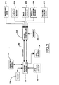
- baler 50 is shown to include an implement controller 200 and several sensors for monitoring operation of the baler.
- Monitoring sensors include an emergency stop input 210, tailgate position sensor 220, crop pickup position sensor 230, bale wrapper position sensor 240, and a bale size monitor 250 which allow implement controller 200 to sense the position of various baler sub-systems.
- More advanced balers may include servos or other actuator devices that may be configured to receive control action signals from implement controller 200 thus allowing the controller 200 to monitor and manage actions within the implement.
- Such advanced control systems are not essential to the implement of the present invention and are thus not discussed further herein, other than noting that the present invention may be implemented on an implement control system that monitors and manages key implement sub-systems.
- the tractor controller 100 and the baler controller 200 are preferrably digital controllers.
- Each of the controllers includes a digital control and communication interface which enables the controllers to communicate over a shared electronic controller area network communications bus 150.
- the communications bus is also referred to herein as a CAN bus. Further information on the CAN bus systems is provided in U.S. Patent No. 6,907,331 issued to Paquet, the descriptive portions being incorporated herein by reference. While a serial communications protocol is described, use of other protocols (e.g., parallel) are equally suitable and thus are not precluded by this invention.
- existing sensors on the implement which provide input to implement controller 200 are used as inputs for the PTO clutch control 26 on the tractor in a manner that will change the state of the PTO (operating or non-operating) in response to conditions in the implement.
- Communication between the implement controller 200 and the tractor controller 100 is enabled by a CAN bus 150 which extends from tractor to implement.
- tailgate position sensor 220 senses the movement and directs a signal to the implement controller 200.
- Implement controller 200 communicating with the tractor controller 100, directs the cessation of the PTO by disengagement of the PTO clutch.
- controller 200 When the tailgate is lowered, again sensed by tailgate position sensor 220, controller 200 will initiate a signal to tractor controller 100 to re-activate the PTO.
- the state of the PTO operation can be altered based on the position of the crop pick-up unit 56, sensed by crop pick-up position sensor 230, operation of the bale wrapper 52, completion of the wrapping process being sensed by wrapper sensor 240 indicating that PTO operation should be suspended in preparation of the tailgate opening.
- An implement protection feature can easily be incorporated by enabling the maximum torque rating of a powered implement to be input into the control system as a pre-selected value, either stored in an on-implement memory module 205 for access by the implement controller 200 or manually entered using the operator interface 110 on the tractor and stored in the tractor controller memory 105 or in the on-implement memory module 205. Operation of the implement above the maximum torque generally indicates that a problem exists within the implement, such as a crop material jam.
- the tractor controller 100 by monitoring the PTO torque from PTO torque sensor 102, can initiate a signal to disengage the PTO clutch 26 to suspend operation of the PTO when the torque being delivered to the implement exceeds a pre-selected value.
- Implement operational efficiency can be improved by providing an indication of the torque being supplied to the implement by the PTO in relation to the pre-selected torque threshold. Such an indication could then be observed by an operator and used to adjust tractor-implement ground speed to maintain operation of the implement as close to the torque threshold as possible thereby maximizing implement utilization efficiency. It is noted that such protective features may find utility on numerous PTO-driven implements, and is thus not limited to application on agricultural round balers.
- operator safety in a system incorporating the invention is improved by programming the tractor controller 100 to require an operator acknowledgement input (via the operator interface 110) before tractor controller 100 initiates a signal to engage the PTO drive clutch.
- Such an interlock prevents an inadvertent or unexpected actuation of the PTO drive.
- Further improvements in safety are provided by incorporating an implement-mounted emergency stop switch 210 which is capable of suspending operating of the tractor PTO when activated.
- the emergency stop switch 210 provides an input to the baler controller 200 which is then communicated to the tractor controller 100 where a PTO disengage signal is generated to disengage the PTO clutch.
Landscapes
- Life Sciences & Earth Sciences (AREA)
- Environmental Sciences (AREA)
- Agricultural Machines (AREA)
- Harvester Elements (AREA)
Claims (15)
- Système de commande, destiné à gérer le fonctionnement d'une prise de force (20) sur un tracteur agricole (10) actionnant un outil accouplé, ladite prise de force (20) pouvant être commandée entre un état embrayé et un état débrayé, le dit système de commande comprenant :- un actionneur agencé sur ledit tracteur (10) destiné à déplacer ladite prise de force (20) entre ledit état embrayé et ledit état débrayé,- un premier contrôleur (100) disposé sur ledit tracteur (10) et configuré pour engendrer un signal d'actionneur qui fait déplacer ledit actionneur entre les dits états embrayé et débrayé,- au moins un capteur de position de partie mobile (220, 230, 240, 250) disposé sur l'outil, ledit au moins un capteur de position (220, 230, 240, 250) étant configuré pour engendrer un signal de position d'outil correspondant à des changements dans une position de partie d'outil entre une première et une seconde position,- un second contrôleur (200) disposé sur ledit outil, ledit second système de contrôleur étant configuré pour recevoir ledit signal de position d'outil du dit au moins un capteur de position (220, 230, 240, 250) et produire au moins un signal de sortie d'outil en réaction, etcaractérisé en ce que ledit système de commande comprend en plus un bus de communication (150) reliant ledit premier contrôleur (100) au dit second contrôleur (200) et configuré pour transmettre des signaux entre le premier et le second contrôleurs (100, 200), moyennant quoi ledit premier contrôleur (100) est configuré pour recevoir ledit au moins un signal de sortie d'outil et engendrer un changement dans l'état de la prise de force (20), et dans lequel ledit capteur de position de partie mobile (220, 230, 240, 250) n'est pas un capteur de position de capot actionné manuellement.
- Système de commande selon la revendication 1, caractérisé en ce que ledit actionneur est un mécanisme d'accouplement (26) mobile entre des positions embrayée et débrayée correspondant respectivement aux dits états embrayé et débrayé, sous l'effet du dit signal d'actionneur.
- Système de commande selon la revendication 1 ou 2, caractérisé en ce que ledit outil est une presse à balles rondes (50) comportant un capot arrière, ledit capot arrière étant mobile entre des positions ouverte et fermée, ledit au moins un capteur de position (220) est configuré pour détecter ladite position du capot arrière, et en ce que lesdites positions ouverte et fermée correspondent respectivement aux dites première et seconde positions.
- Système de commande selon l'une quelconque des revendications précédentes, caractérisé en ce que ledit outil est une presse à balles rondes (50) comportant un dispositif de ramassage (56) de produit de récolte, ledit dispositif de ramassage étant mobile entre des positions levée et abaissée, ledit au moins un capteur de position (230) étant configuré pour détecter ladite position du dispositif de ramassage, et en ce que lesdites positions levée et abaissée correspondent respectivement aux dites première et seconde positions.
- Système de commande selon l'une quelconque des revendications précédentes, caractérisé en ce que ledit outil est une presse à balles rondes (50), comportant un dispositif pour envelopper les balles, ledit dispositif d'enveloppement étant mobile entre une position d'enveloppement et une position d'attente, ledit au moins un capteur de position (240) est configuré pour détecter la position du dit dispositif d'enveloppement, et en ce que lesdites positions d'enveloppement et d'attente correspondent respectivement aux dites première et seconde positions.
- Système de commande selon l'une quelconque des revendications précédentes, comprenant en plus un bouton d'arrêt d'urgence (210), disposé sur ledit outil, le dit bouton d'arrêt (210) ayant des sorties correspondant à un état d'arrêt et un état de marche, ledit bouton d'arrêt (210) étant connecté au dit second contrôleur (200) et configuré de telle sorte que, lorsque ledit signal d'état d'arrêt est reçu par ledit second contrôleur (200) et communiqué au dit premier contrôleur (100), ladite prise de force (20) est débrayée.
- Système de commande selon l'une quelconque des revendications précédentes, caractérisé en ce que ledit bus de communication (150) est un réseau de communication numérique, le système de commande comprenant en plus un module de mémoire (105, 205) connecté au dit premier contrôleur (100) ou au dit second contrôleur (200) et un capteur de couple (102) disposé sur le tracteur (10), ledit module de mémoire (105, 205) étant configuré pour stocker une valeur présélectionnée correspondant à un seuil de couple, ledit capteur de couple (102) générant une valeur de couple en cours et ledit premier contrôleur (100) engendrant ledit signal d'actionneur pour débrayer ladite prise de force (20) lorsque ladite valeur de couple en cours est égale ou supérieure audit seuil de couple.
- Système de commande selon la revendication 7, comprenant en plus une interface de conducteur (110) comportant un afficheur, ledit afficheur étant configuré pour indiquer ladite valeur de couple en cours à un conducteur de tracteur, caractérisé en ce que ledit afficheur est configuré pour indiquer ladite valeur de couple en cours par rapport à ladite valeur présélectionnée et en ce que ledit bus de communication (150) transmet des signaux de façon bidirectionnelle entre les dits premier et second contrôleurs (100, 200) et/ou l'interface du conducteur (110) sert d'entrée d'acceptation du conducteur avant que le tracteur (10) ne déclenche un signal pour embrayer ledit actionneur.
- Procédé de commande de la prise de force (20) sur un tracteur agricole (10), ledit tracteur (10) comportant une presse à balles rondes accouplée (50) à celui-ci et actionnée par ladite prise de force (20), le dit procédé de commande comprenant les étapes consistant à:- prévoir un actionneur agencé sur ledit tracteur (10) destiné à déplacer ladite prise de force (20) entre un état embrayé et un état débrayé,- prévoir un premier contrôleur (100) disposé sur ledit tracteur (10) et configuré pour engendrer un signal d'actionneur qui fait déplacer ledit actionneur entre les dits états embrayé et débrayé,- prévoir au moins un capteur de position de partie mobile (220, 230, 240, 250) disposé sur l'outil, ledit au moins un capteur de position (220, 230, 240, 250) étant configuré pour engendrer un signal de position d'outil correspondant à des changements dans une position de partie d'outil entre une première et une seconde position;- prévoir un second contrôleur (200) disposé sur ledit outil, ledit second système de contrôleur étant configuré pour recevoir ledit signal de position d'outil du dit au moins un capteur de position (220, 230, 240, 250) et produire au moins un signal de sortie d'outil en réaction; etcaractérisé en ce que le procédé comprend en plus les étapes consistant à :- un bus de communication (150) reliant ledit premier contrôleur (100) au dit second contrôleur (200) et configuré pour transmettre des signaux entre le premier et le second contrôleurs (100, 200);- faire fonctionner ledit tracteur et l'outil accouplé,- changer la position de la presse à balles de la première position à la seconde position,- détecter, par au moins ledit un capteur de position (220, 230, 240), le changement de position de la presse à balles et initier le signal de position d'outil, dans lequel ledit capteur de position de pièce mobile (220, 230, 240, 250) n'est pas un capteur de position de capot actionné manuellement,- recevoir par ledit second contrôleur (200) le signal de position d'outil,- communiquer via ledit bus de communication (150) entre ledit second contrôleur (200) et ledit premier contrôleur (100) en réponse au dit signal de position d'outil, et- engendrer par le dit premier contrôleur (100), en réponse à la communication avec ledit second contrôleur (200), un signal de sortie configuré pour modifier l'état de la prise de force.
- Procédé selon la revendication 9, caractérisé en ce que ledit actionneur est un mécanisme d'accouplement (26) mobile entre des positions embrayée et débrayée correspondant respectivement aux états embrayé et débrayé, en réaction au dit signal d'actionneur.
- Procédé selon l'une des revendications 9 ou 10, caractérisé en ce que ladite presse à balles rondes (50) comprend un capot arrière étant mobile entre des positions ouverte et fermée, ledit au moins un capteur de position (220) est configuré pour détecter ladite position du capot arrière, et en ce que lesdites positions ouverte et fermée correspondent respectivement aux dites première et seconde positions.
- Procédé selon les revendications 9 à 11, caractérisé en ce que cette presse à balles rondes (50) comporte un dispositif de ramassage (56) de produit de récolte, ledit dispositif de ramassage est mobile entre des positions levée et abaissée, ledit au moins un capteur de position (230) étant configuré pour détecter ladite position du dispositif de ramassage, et en ce que lesdites positions levée et abaissée correspondent respectivement aux dites première et seconde positions.
- Procédé selon les revendications 9 à 12, caractérisé en ce que cette presse à balles rondes (50) comporte un dispositif pour envelopper les balles, ledit dispositif d'enveloppement étant mobile entre une position d'enveloppement et une position d'attente, ledit au moins un capteur de position (240) étant configuré pour détecter la position du dit dispositif d'enveloppement, et en ce que lequel lesdites positions d'enveloppement et d'attente correspondent respectivement aux dites première et seconde positions.
- Procédé selon les revendications 9 à 13, comprenant en outre les étapes consistant à :- prévoir un bouton d'arrêt d'urgence (210) sur ladite presse à balles (50) ayant des sorties correspondant à un état d'arrêt et un état de marche,- déclencher un arrêt d'urgence par l'actionnement du bouton d'arrêt d'urgence (210),- recevoir par ledit second contrôleur (200) la sortie correspondant à l'état d'arrêt,- communiquer via ledit bus de communication (150) entre ledit second contrôleur (200) et ledit premier contrôleur (100) correspondant à l'état d'arrêt d'urgence; et- engendrer par le dit premier contrôleur (100), en réponse à la communication avec ledit second contrôleur (200), un signal de sortie configuré pour modifier l'état de la prise de force et débrayer la prise de force.
- Procédé selon les revendications 9 à 14, comprenant les étapes consistant à :- prévoir un module de mémoire (105, 205) connecté audit premier contrôleur (100) ou au dit second contrôleur (200), ledit module de mémoire (105, 205) étant configuré pour enregistrer une valeur présélectionnée correspondant à un seuil de couple,- prévoir un capteur de couple (102) disposé sur ledit tracteur (10), ledit capteur de couple (102) générant une valeur de couple en cours,- entrer ladite valeur de couple présélectionnée dans ledit module de mémoire (105, 205),- détecter par ledit capteur de couple (102) le couple en cours de ladite prise de force (20),- comparer au moyen du dit premier contrôleur (100) ladite valeur de couple en cours et ladite valeur présélectionnée, et- engendrer par ledit premier contrôleur (100) un signal d'actionneur pour débrayer ladite prise de force (20) lorsque ladite valeur du couple en cours est égale ou supérieure à ladite valeur de couple présélectionnée.
Applications Claiming Priority (1)
| Application Number | Priority Date | Filing Date | Title |
|---|---|---|---|
| US12/555,008 US8311709B2 (en) | 2009-09-08 | 2009-09-08 | Implement initiated control of tractor power take-off (PTO) |
Publications (3)
| Publication Number | Publication Date |
|---|---|
| EP2292085A1 EP2292085A1 (fr) | 2011-03-09 |
| EP2292085B1 true EP2292085B1 (fr) | 2012-03-14 |
| EP2292085B2 EP2292085B2 (fr) | 2020-09-09 |
Family
ID=43031473
Family Applications (1)
| Application Number | Title | Priority Date | Filing Date |
|---|---|---|---|
| EP10175443.0A Active EP2292085B2 (fr) | 2009-09-08 | 2010-09-06 | Contrôle d'outil de prise de mouvement de tracteur |
Country Status (3)
| Country | Link |
|---|---|
| US (1) | US8311709B2 (fr) |
| EP (1) | EP2292085B2 (fr) |
| AT (1) | ATE548910T1 (fr) |
Families Citing this family (26)
| Publication number | Priority date | Publication date | Assignee | Title |
|---|---|---|---|---|
| US8206205B2 (en) * | 2009-05-12 | 2012-06-26 | Deere & Company | Method of unplugging control for a feeding system |
| DE102011102525A1 (de) * | 2011-05-26 | 2012-11-29 | Maschinenfabrik Bernard Krone Gmbh | Kombination aus einem Zugfahrzeug und einer landwirtschaftlichen Aufsammelpresse |
| DE102013100793A1 (de) * | 2013-01-28 | 2014-07-31 | Usines Claas France S.A.S. | Kombination aus einem Zugfahrzeug und einer davon gezogenen landwirtschaftlichen Erntemaschine |
| US8776679B1 (en) * | 2013-03-15 | 2014-07-15 | Cnh Industrial Canada, Ltd. | Semi-automatic bale ejection sequence |
| US20140261023A1 (en) * | 2013-03-15 | 2014-09-18 | Cnh Industrial America Llc | Bale forming control system and method |
| BE1021141B1 (nl) | 2013-04-15 | 2016-01-08 | Cnh Industrial Belgium Nv | Vliegwielopstartsysteem |
| DE102013104934A1 (de) * | 2013-05-14 | 2014-11-20 | Usines Claas France S.A.S. | Kombination aus einem Zugfahrzeug und einer landwirtschaftlichen Ballenpresse |
| NL2011682C2 (en) * | 2013-10-28 | 2015-04-29 | Forage Innovations Bv | Bale forming apparatus and method with overload protection. |
| US9008920B1 (en) * | 2013-12-05 | 2015-04-14 | Cnh Industrial America Llc | Baler automatic stopping sequence |
| US9980437B2 (en) | 2014-03-25 | 2018-05-29 | CNH Industrial American LLC | Baling system having a bale position sensor |
| US10316492B2 (en) * | 2014-07-31 | 2019-06-11 | Cnh Industrial America Llc | Active force/vibration feedback control method and apparatus for a movable machine |
| JP2016049029A (ja) * | 2014-08-28 | 2016-04-11 | 株式会社Ihiスター | 農作業機、走行車、および、農作業車両システム |
| US9883626B2 (en) * | 2015-10-02 | 2018-02-06 | Deere & Company | Controlling an agricultural vehicle based on sensed inputs |
| DE102017200528A1 (de) * | 2017-01-13 | 2018-07-19 | Zf Friedrichshafen Ag | Antriebsstrang eines Fahrzeuges |
| DE102017127824B3 (de) * | 2017-11-24 | 2018-12-13 | B. Strautmann & Söhne GmbH u. Co. KG | Selbstfahrende Arbeitsmaschine mit wenigstens zwei Steuerungseinrichtungen |
| JP6854258B2 (ja) * | 2018-03-30 | 2021-04-07 | ヤンマーパワーテクノロジー株式会社 | 作業車両 |
| EP3569055B1 (fr) * | 2018-05-18 | 2021-04-07 | Deere & Company | Presse à balles rondes |
| US10645857B2 (en) | 2018-07-27 | 2020-05-12 | Cnh Industrial America Llc | Implement control system having a manual override |
| US11596105B2 (en) | 2019-10-30 | 2023-03-07 | Cnh Industrial America Llc | Drive system for an agricultural baler |
| US11589514B2 (en) | 2019-10-30 | 2023-02-28 | Cnh Industrial America Llc | Pickup drive system for an agricultural baler |
| US11320006B2 (en) * | 2020-01-17 | 2022-05-03 | Zimeno, Inc. | Power takeoff control |
| US11974522B2 (en) * | 2020-12-23 | 2024-05-07 | Cnh Industrial America Llc | Method and control system for controlling baler power-take-off speed |
| GB202114623D0 (en) | 2021-10-13 | 2021-11-24 | Agco Int Gmbh | Baling apparatus |
| US12304308B2 (en) | 2022-09-19 | 2025-05-20 | Ford Global Technologies, Llc | Methods and systems for operating a peripheral device of a vehicle |
| US12025189B1 (en) | 2023-02-07 | 2024-07-02 | Cnh Industrial America Llc | In-line compact baler declutch mechanism |
| EP4635290A1 (fr) * | 2024-04-16 | 2025-10-22 | Kverneland Group Ravenna S.r.l. | Procédé de formation d'une balle par une presse à balles, système agricole et presse à balles |
Family Cites Families (41)
| Publication number | Priority date | Publication date | Assignee | Title |
|---|---|---|---|---|
| NL7811964A (nl) | 1978-12-08 | 1980-06-10 | Lely Nv C Van Der | Trekker. |
| US4296596A (en) | 1979-03-29 | 1981-10-27 | Sperry Corporation | Automatic bale ejection drive |
| US4715012A (en) | 1980-10-15 | 1987-12-22 | Massey-Ferguson Services N.V. | Electronic tractor control |
| US4306403A (en) | 1980-10-17 | 1981-12-22 | Deere & Company | Overload sensor for a cotton harvester unit drive |
| DE3468615D1 (en) * | 1984-01-27 | 1988-02-18 | Deere John | Rotobaler with means for raising the tension in the belts |
| US4674403A (en) * | 1985-08-27 | 1987-06-23 | New Holland Inc. | Semi-automatic baler control and indicator system |
| US5136831A (en) * | 1986-08-04 | 1992-08-11 | Hay & Forage Industries | Continuous round baler and method |
| EP0264493B1 (fr) * | 1986-10-21 | 1989-12-20 | Ford New Holland N.V. | Presse à balles rondes |
| US4899651A (en) * | 1988-10-11 | 1990-02-13 | Ford New Holland, Inc. | Apron tensioning system for round balers |
| US5557510A (en) | 1993-11-29 | 1996-09-17 | Gehl Company | Control system for a large round baler |
| US5740044A (en) | 1995-06-16 | 1998-04-14 | Caterpillar Inc. | Torque limiting power take off control and method of operating same |
| GB9623784D0 (en) | 1996-11-15 | 1997-01-08 | Massey Ferguson Sa | PTQ shaft monitoring & control system |
| DE19701421A1 (de) | 1997-01-17 | 1998-07-23 | Welger Geb | Rundballenpresse für landwirtschaftliche Halmgüter |
| DE19725699C2 (de) * | 1997-06-18 | 2000-11-02 | Lely Welger Maschinenfabrik Gm | Rundballenpresse für landwirtschaftliche Erntegüter |
| US5839362A (en) * | 1997-07-21 | 1998-11-24 | Hay & Forage Industries | Single cylinder hydraulic tension control system for round balers |
| DE19748748C2 (de) | 1997-11-05 | 2000-06-15 | Lely Welger Maschinenfabrik Gm | Kanalballenpresse mit einer Regeleinrichtung |
| US6173225B1 (en) | 1999-04-20 | 2001-01-09 | Case Corporation | Power takeoff control system |
| GB2362127B (en) | 2000-05-13 | 2002-05-22 | Ford New Holland Nv | Method and apparatus for controlling a tractor/baler combination |
| US6553902B2 (en) * | 2000-06-29 | 2003-04-29 | New Holland North America, Inc. | Method for calculating a value relating to a feed rate of crop entering a baler |
| US6430904B1 (en) | 2001-05-09 | 2002-08-13 | Deere & Company | Platform auger torque sensing brake activation |
| EP1273217A1 (fr) * | 2001-07-03 | 2003-01-08 | Lely Enterprises AG | Machine agricole |
| DE10145407C2 (de) | 2001-09-14 | 2003-11-13 | Walterscheid Gmbh Gkn | Antriebsanordnung und Verfahren zum Festsetzen mindestens eines Arbeitsaggregats |
| DE10145643C1 (de) | 2001-09-15 | 2002-11-07 | Case Steyr Landmaschinentechni | Regelung für den Antrieb einer Zapfwelle an einem Landfahrzeug |
| GB0213197D0 (en) | 2002-06-10 | 2002-07-17 | Cnh Belgium Nv | Vehicle control system and apparatus therefor |
| US6758292B2 (en) | 2002-08-12 | 2004-07-06 | Deere & Company | Interlock system and a detent switch therefor |
| DE10241216A1 (de) | 2002-09-06 | 2004-03-18 | Deere & Company, Moline | Nachweiseinrichtung zum Nachweis eines Gutstaus in einer Erntemaschine |
| US7048106B2 (en) | 2004-03-26 | 2006-05-23 | Cnh America Llc | Power take-off control system and method |
| US7416068B2 (en) | 2004-11-03 | 2008-08-26 | Borgwarner Inc. | Power take-off clutch control system |
| DE102005002880A1 (de) | 2005-01-21 | 2006-08-17 | Deere & Company, Moline | Antriebsanordnung einer landwirtschaftlichen Arbeitsmaschine |
| GB0507928D0 (en) | 2005-04-20 | 2005-05-25 | Cnh Belgium Nv | Input device for agricultural vehicle information display |
| US7399255B1 (en) | 2005-06-10 | 2008-07-15 | Polaris Industries Inc. | Engine and transmission control system and method for a vehicle accessory |
| US7404355B2 (en) * | 2006-01-31 | 2008-07-29 | Deere & Company | Tractor and baler combination with automatic baling and tractor halt control |
| US7699734B2 (en) * | 2007-03-13 | 2010-04-20 | Agco Corporation | Drive belt removal apparatus in confined spaces |
| DE102007032309A1 (de) * | 2007-07-11 | 2009-01-15 | Deere & Company, Moline | Bedienvorrichtung |
| US20090223197A1 (en) * | 2008-03-06 | 2009-09-10 | Kohlbeck Cyril D | Leaf bailer |
| DE102008018541A1 (de) * | 2008-04-12 | 2009-10-15 | Deere & Company, Moline | Kombination aus einem landwirtschaftlichen Gerät und einem Träger- oder Zugfahrzeug mit einem Sensor zur Erfassung des Öffnungszustands einer Abdeckung und einer automatischen Abschaltung der Zapfwelle |
| DE102008041075A1 (de) * | 2008-08-07 | 2010-02-11 | Deere & Company, Moline | Antriebsanordnung und Verfahren zum Antrieb eines landwirtschaftlichen Arbeitsgeräts |
| US7963734B2 (en) * | 2008-08-14 | 2011-06-21 | Ernest Robert Bruha | Bale handling implement |
| US7849791B2 (en) * | 2008-11-10 | 2010-12-14 | Cnh America Llc | Optimized baler tailgate cycle |
| US7871028B2 (en) * | 2009-01-30 | 2011-01-18 | Roy Marschall | Chopper unit for baled vegetable material such as straw |
| US8051771B2 (en) * | 2009-06-30 | 2011-11-08 | Cnh America Llc | Belt routing in a round baler |
-
2009
- 2009-09-08 US US12/555,008 patent/US8311709B2/en active Active
-
2010
- 2010-09-06 EP EP10175443.0A patent/EP2292085B2/fr active Active
- 2010-09-06 AT AT10175443T patent/ATE548910T1/de active
Also Published As
| Publication number | Publication date |
|---|---|
| US8311709B2 (en) | 2012-11-13 |
| EP2292085A1 (fr) | 2011-03-09 |
| ATE548910T1 (de) | 2012-03-15 |
| US20110060507A1 (en) | 2011-03-10 |
| EP2292085B2 (fr) | 2020-09-09 |
Similar Documents
| Publication | Publication Date | Title |
|---|---|---|
| EP2292085B1 (fr) | Contrôle d'outil de prise de mouvement de tracteur | |
| US8577559B2 (en) | Drive arrangement and process for the drive of an agricultural implement | |
| BE1019006A3 (nl) | Een tractor met een stuurinrichting. | |
| US7640721B2 (en) | Tractor and baler combination with automatic baling and steering control | |
| US11172619B2 (en) | Agricultural baling machine clutch control | |
| US8517158B2 (en) | Agricultural implement and a vehicle combination having a sensor to detect the open condition of a cover | |
| US11871701B2 (en) | Baling machine including a drive-transferring driveline | |
| GB2486730A (en) | A control system for a power takeoff (PTO) stub of an agricultural tractor | |
| EP1595734A1 (fr) | Sytème de contrôle, notamment pour un tracteur | |
| US7186201B2 (en) | Active combine rotor deceleration | |
| US11950539B2 (en) | Agricultural system | |
| US11968929B2 (en) | Agricultural system | |
| EP4165962B1 (fr) | Appareil de mise en balles | |
| KR20240050667A (ko) | 베일러 장착 트랙터의 구동장치 및 구동방법 | |
| US20250133999A1 (en) | System and method for determining the clutch status of an agricultural baler |
Legal Events
| Date | Code | Title | Description |
|---|---|---|---|
| PUAI | Public reference made under article 153(3) epc to a published international application that has entered the european phase |
Free format text: ORIGINAL CODE: 0009012 |
|
| AK | Designated contracting states |
Kind code of ref document: A1 Designated state(s): AL AT BE BG CH CY CZ DE DK EE ES FI FR GB GR HR HU IE IS IT LI LT LU LV MC MK MT NL NO PL PT RO SE SI SK SM TR |
|
| AX | Request for extension of the european patent |
Extension state: BA ME RS |
|
| GRAP | Despatch of communication of intention to grant a patent |
Free format text: ORIGINAL CODE: EPIDOSNIGR1 |
|
| 17P | Request for examination filed |
Effective date: 20110909 |
|
| GRAS | Grant fee paid |
Free format text: ORIGINAL CODE: EPIDOSNIGR3 |
|
| GRAA | (expected) grant |
Free format text: ORIGINAL CODE: 0009210 |
|
| AK | Designated contracting states |
Kind code of ref document: B1 Designated state(s): AL AT BE BG CH CY CZ DE DK EE ES FI FR GB GR HR HU IE IS IT LI LT LU LV MC MK MT NL NO PL PT RO SE SI SK SM TR |
|
| REG | Reference to a national code |
Ref country code: GB Ref legal event code: FG4D |
|
| REG | Reference to a national code |
Ref country code: AT Ref legal event code: REF Ref document number: 548910 Country of ref document: AT Kind code of ref document: T Effective date: 20120315 Ref country code: CH Ref legal event code: EP |
|
| REG | Reference to a national code |
Ref country code: IE Ref legal event code: FG4D |
|
| REG | Reference to a national code |
Ref country code: DE Ref legal event code: R096 Ref document number: 602010001043 Country of ref document: DE Effective date: 20120510 |
|
| REG | Reference to a national code |
Ref country code: NL Ref legal event code: VDEP Effective date: 20120314 |
|
| PG25 | Lapsed in a contracting state [announced via postgrant information from national office to epo] |
Ref country code: HR Free format text: LAPSE BECAUSE OF FAILURE TO SUBMIT A TRANSLATION OF THE DESCRIPTION OR TO PAY THE FEE WITHIN THE PRESCRIBED TIME-LIMIT Effective date: 20120314 Ref country code: LT Free format text: LAPSE BECAUSE OF FAILURE TO SUBMIT A TRANSLATION OF THE DESCRIPTION OR TO PAY THE FEE WITHIN THE PRESCRIBED TIME-LIMIT Effective date: 20120314 Ref country code: NO Free format text: LAPSE BECAUSE OF FAILURE TO SUBMIT A TRANSLATION OF THE DESCRIPTION OR TO PAY THE FEE WITHIN THE PRESCRIBED TIME-LIMIT Effective date: 20120614 |
|
| LTIE | Lt: invalidation of european patent or patent extension |
Effective date: 20120314 |
|
| PG25 | Lapsed in a contracting state [announced via postgrant information from national office to epo] |
Ref country code: LV Free format text: LAPSE BECAUSE OF FAILURE TO SUBMIT A TRANSLATION OF THE DESCRIPTION OR TO PAY THE FEE WITHIN THE PRESCRIBED TIME-LIMIT Effective date: 20120314 Ref country code: GR Free format text: LAPSE BECAUSE OF FAILURE TO SUBMIT A TRANSLATION OF THE DESCRIPTION OR TO PAY THE FEE WITHIN THE PRESCRIBED TIME-LIMIT Effective date: 20120615 Ref country code: FI Free format text: LAPSE BECAUSE OF FAILURE TO SUBMIT A TRANSLATION OF THE DESCRIPTION OR TO PAY THE FEE WITHIN THE PRESCRIBED TIME-LIMIT Effective date: 20120314 |
|
| REG | Reference to a national code |
Ref country code: AT Ref legal event code: MK05 Ref document number: 548910 Country of ref document: AT Kind code of ref document: T Effective date: 20120314 |
|
| PG25 | Lapsed in a contracting state [announced via postgrant information from national office to epo] |
Ref country code: CY Free format text: LAPSE BECAUSE OF FAILURE TO SUBMIT A TRANSLATION OF THE DESCRIPTION OR TO PAY THE FEE WITHIN THE PRESCRIBED TIME-LIMIT Effective date: 20120314 |
|
| PG25 | Lapsed in a contracting state [announced via postgrant information from national office to epo] |
Ref country code: CZ Free format text: LAPSE BECAUSE OF FAILURE TO SUBMIT A TRANSLATION OF THE DESCRIPTION OR TO PAY THE FEE WITHIN THE PRESCRIBED TIME-LIMIT Effective date: 20120314 Ref country code: RO Free format text: LAPSE BECAUSE OF FAILURE TO SUBMIT A TRANSLATION OF THE DESCRIPTION OR TO PAY THE FEE WITHIN THE PRESCRIBED TIME-LIMIT Effective date: 20120314 Ref country code: EE Free format text: LAPSE BECAUSE OF FAILURE TO SUBMIT A TRANSLATION OF THE DESCRIPTION OR TO PAY THE FEE WITHIN THE PRESCRIBED TIME-LIMIT Effective date: 20120314 Ref country code: SI Free format text: LAPSE BECAUSE OF FAILURE TO SUBMIT A TRANSLATION OF THE DESCRIPTION OR TO PAY THE FEE WITHIN THE PRESCRIBED TIME-LIMIT Effective date: 20120314 Ref country code: IS Free format text: LAPSE BECAUSE OF FAILURE TO SUBMIT A TRANSLATION OF THE DESCRIPTION OR TO PAY THE FEE WITHIN THE PRESCRIBED TIME-LIMIT Effective date: 20120714 Ref country code: PL Free format text: LAPSE BECAUSE OF FAILURE TO SUBMIT A TRANSLATION OF THE DESCRIPTION OR TO PAY THE FEE WITHIN THE PRESCRIBED TIME-LIMIT Effective date: 20120314 Ref country code: SE Free format text: LAPSE BECAUSE OF FAILURE TO SUBMIT A TRANSLATION OF THE DESCRIPTION OR TO PAY THE FEE WITHIN THE PRESCRIBED TIME-LIMIT Effective date: 20120314 Ref country code: BE Free format text: LAPSE BECAUSE OF FAILURE TO SUBMIT A TRANSLATION OF THE DESCRIPTION OR TO PAY THE FEE WITHIN THE PRESCRIBED TIME-LIMIT Effective date: 20120314 |
|
| PG25 | Lapsed in a contracting state [announced via postgrant information from national office to epo] |
Ref country code: SK Free format text: LAPSE BECAUSE OF FAILURE TO SUBMIT A TRANSLATION OF THE DESCRIPTION OR TO PAY THE FEE WITHIN THE PRESCRIBED TIME-LIMIT Effective date: 20120314 Ref country code: PT Free format text: LAPSE BECAUSE OF FAILURE TO SUBMIT A TRANSLATION OF THE DESCRIPTION OR TO PAY THE FEE WITHIN THE PRESCRIBED TIME-LIMIT Effective date: 20120716 |
|
| PLBI | Opposition filed |
Free format text: ORIGINAL CODE: 0009260 |
|
| PLAX | Notice of opposition and request to file observation + time limit sent |
Free format text: ORIGINAL CODE: EPIDOSNOBS2 |
|
| 26 | Opposition filed |
Opponent name: OCTROOIBUREAU VAN DER LELY N.V. Effective date: 20121213 |
|
| PG25 | Lapsed in a contracting state [announced via postgrant information from national office to epo] |
Ref country code: AT Free format text: LAPSE BECAUSE OF FAILURE TO SUBMIT A TRANSLATION OF THE DESCRIPTION OR TO PAY THE FEE WITHIN THE PRESCRIBED TIME-LIMIT Effective date: 20120314 Ref country code: NL Free format text: LAPSE BECAUSE OF FAILURE TO SUBMIT A TRANSLATION OF THE DESCRIPTION OR TO PAY THE FEE WITHIN THE PRESCRIBED TIME-LIMIT Effective date: 20120314 Ref country code: DK Free format text: LAPSE BECAUSE OF FAILURE TO SUBMIT A TRANSLATION OF THE DESCRIPTION OR TO PAY THE FEE WITHIN THE PRESCRIBED TIME-LIMIT Effective date: 20120314 |
|
| REG | Reference to a national code |
Ref country code: DE Ref legal event code: R026 Ref document number: 602010001043 Country of ref document: DE Effective date: 20121213 |
|
| PG25 | Lapsed in a contracting state [announced via postgrant information from national office to epo] |
Ref country code: MC Free format text: LAPSE BECAUSE OF NON-PAYMENT OF DUE FEES Effective date: 20120930 Ref country code: ES Free format text: LAPSE BECAUSE OF FAILURE TO SUBMIT A TRANSLATION OF THE DESCRIPTION OR TO PAY THE FEE WITHIN THE PRESCRIBED TIME-LIMIT Effective date: 20120625 |
|
| PLBB | Reply of patent proprietor to notice(s) of opposition received |
Free format text: ORIGINAL CODE: EPIDOSNOBS3 |
|
| REG | Reference to a national code |
Ref country code: IE Ref legal event code: MM4A |
|
| PG25 | Lapsed in a contracting state [announced via postgrant information from national office to epo] |
Ref country code: IE Free format text: LAPSE BECAUSE OF NON-PAYMENT OF DUE FEES Effective date: 20120906 Ref country code: BG Free format text: LAPSE BECAUSE OF FAILURE TO SUBMIT A TRANSLATION OF THE DESCRIPTION OR TO PAY THE FEE WITHIN THE PRESCRIBED TIME-LIMIT Effective date: 20120614 |
|
| PG25 | Lapsed in a contracting state [announced via postgrant information from national office to epo] |
Ref country code: MT Free format text: LAPSE BECAUSE OF FAILURE TO SUBMIT A TRANSLATION OF THE DESCRIPTION OR TO PAY THE FEE WITHIN THE PRESCRIBED TIME-LIMIT Effective date: 20120314 Ref country code: AL Free format text: LAPSE BECAUSE OF FAILURE TO SUBMIT A TRANSLATION OF THE DESCRIPTION OR TO PAY THE FEE WITHIN THE PRESCRIBED TIME-LIMIT Effective date: 20120314 |
|
| PG25 | Lapsed in a contracting state [announced via postgrant information from national office to epo] |
Ref country code: TR Free format text: LAPSE BECAUSE OF FAILURE TO SUBMIT A TRANSLATION OF THE DESCRIPTION OR TO PAY THE FEE WITHIN THE PRESCRIBED TIME-LIMIT Effective date: 20120314 |
|
| RAP2 | Party data changed (patent owner data changed or rights of a patent transferred) |
Owner name: CNH INDUSTRIAL ITALIA S.P.A. |
|
| PG25 | Lapsed in a contracting state [announced via postgrant information from national office to epo] |
Ref country code: SM Free format text: LAPSE BECAUSE OF FAILURE TO SUBMIT A TRANSLATION OF THE DESCRIPTION OR TO PAY THE FEE WITHIN THE PRESCRIBED TIME-LIMIT Effective date: 20120314 Ref country code: LU Free format text: LAPSE BECAUSE OF NON-PAYMENT OF DUE FEES Effective date: 20120906 |
|
| REG | Reference to a national code |
Ref country code: DE Ref legal event code: R082 Ref document number: 602010001043 Country of ref document: DE Representative=s name: PATENTANWAELTE WALLACH, KOCH & PARTNER, DE |
|
| PG25 | Lapsed in a contracting state [announced via postgrant information from national office to epo] |
Ref country code: HU Free format text: LAPSE BECAUSE OF FAILURE TO SUBMIT A TRANSLATION OF THE DESCRIPTION OR TO PAY THE FEE WITHIN THE PRESCRIBED TIME-LIMIT Effective date: 20100906 |
|
| REG | Reference to a national code |
Ref country code: DE Ref legal event code: R081 Ref document number: 602010001043 Country of ref document: DE Owner name: CNH INDUSTRIAL ITALIA S.P.A., IT Free format text: FORMER OWNER: CNH ITALIA S.P.A., TURIN, IT Effective date: 20140623 Ref country code: DE Ref legal event code: R082 Ref document number: 602010001043 Country of ref document: DE Representative=s name: PATENTANWAELTE WALLACH, KOCH & PARTNER, DE Effective date: 20140623 Ref country code: DE Ref legal event code: R082 Ref document number: 602010001043 Country of ref document: DE Representative=s name: PATENTANWAELTE WALLACH, KOCH, DR. HAIBACH, FEL, DE Effective date: 20140623 |
|
| RDAF | Communication despatched that patent is revoked |
Free format text: ORIGINAL CODE: EPIDOSNREV1 |
|
| APBM | Appeal reference recorded |
Free format text: ORIGINAL CODE: EPIDOSNREFNO |
|
| APBP | Date of receipt of notice of appeal recorded |
Free format text: ORIGINAL CODE: EPIDOSNNOA2O |
|
| APAH | Appeal reference modified |
Free format text: ORIGINAL CODE: EPIDOSCREFNO |
|
| PLAB | Opposition data, opponent's data or that of the opponent's representative modified |
Free format text: ORIGINAL CODE: 0009299OPPO |
|
| R26 | Opposition filed (corrected) |
Opponent name: OCTROOIBUREAU VAN DER LELY N.V. Effective date: 20121213 |
|
| REG | Reference to a national code |
Ref country code: FR Ref legal event code: CD Owner name: CNH INDUSTRIAL ITALIA S.P.A. Effective date: 20150313 |
|
| REG | Reference to a national code |
Ref country code: CH Ref legal event code: PL |
|
| APBQ | Date of receipt of statement of grounds of appeal recorded |
Free format text: ORIGINAL CODE: EPIDOSNNOA3O |
|
| REG | Reference to a national code |
Ref country code: FR Ref legal event code: PLFP Year of fee payment: 6 |
|
| PG25 | Lapsed in a contracting state [announced via postgrant information from national office to epo] |
Ref country code: LI Free format text: LAPSE BECAUSE OF NON-PAYMENT OF DUE FEES Effective date: 20140930 Ref country code: CH Free format text: LAPSE BECAUSE OF NON-PAYMENT OF DUE FEES Effective date: 20140930 Ref country code: MK Free format text: LAPSE BECAUSE OF FAILURE TO SUBMIT A TRANSLATION OF THE DESCRIPTION OR TO PAY THE FEE WITHIN THE PRESCRIBED TIME-LIMIT Effective date: 20120314 |
|
| PLAB | Opposition data, opponent's data or that of the opponent's representative modified |
Free format text: ORIGINAL CODE: 0009299OPPO |
|
| R26 | Opposition filed (corrected) |
Opponent name: OCTROOIBUREAU VAN DER LELY N.V. Effective date: 20121213 |
|
| REG | Reference to a national code |
Ref country code: FR Ref legal event code: PLFP Year of fee payment: 7 |
|
| REG | Reference to a national code |
Ref country code: FR Ref legal event code: PLFP Year of fee payment: 8 |
|
| PLAB | Opposition data, opponent's data or that of the opponent's representative modified |
Free format text: ORIGINAL CODE: 0009299OPPO |
|
| R26 | Opposition filed (corrected) |
Opponent name: OCTROOIBUREAU VAN DER LELY N.V. Effective date: 20121213 |
|
| REG | Reference to a national code |
Ref country code: FR Ref legal event code: PLFP Year of fee payment: 9 |
|
| APBU | Appeal procedure closed |
Free format text: ORIGINAL CODE: EPIDOSNNOA9O |
|
| REG | Reference to a national code |
Ref country code: DE Ref legal event code: R084 Ref document number: 602010001043 Country of ref document: DE |
|
| REG | Reference to a national code |
Ref country code: DE Ref legal event code: R082 Ref document number: 602010001043 Country of ref document: DE Representative=s name: MEISSNER BOLTE PATENTANWAELTE RECHTSANWAELTE P, DE Ref country code: DE Ref legal event code: R082 Ref document number: 602010001043 Country of ref document: DE Representative=s name: KROHER - STROBEL RECHTS- UND PATENTANWAELTE PA, DE Ref country code: DE Ref legal event code: R082 Ref document number: 602010001043 Country of ref document: DE Representative=s name: KROHER STROBEL RECHTS- UND PATENTANWAELTE PART, DE |
|
| PUAH | Patent maintained in amended form |
Free format text: ORIGINAL CODE: 0009272 |
|
| STAA | Information on the status of an ep patent application or granted ep patent |
Free format text: STATUS: PATENT MAINTAINED AS AMENDED |
|
| REG | Reference to a national code |
Ref country code: DE Ref legal event code: R082 Ref document number: 602010001043 Country of ref document: DE Representative=s name: KROHER - STROBEL RECHTS- UND PATENTANWAELTE PA, DE Ref country code: DE Ref legal event code: R082 Ref document number: 602010001043 Country of ref document: DE Representative=s name: KROHER STROBEL RECHTS- UND PATENTANWAELTE PART, DE |
|
| 27A | Patent maintained in amended form |
Effective date: 20200909 |
|
| AK | Designated contracting states |
Kind code of ref document: B2 Designated state(s): AL AT BE BG CH CY CZ DE DK EE ES FI FR GB GR HR HU IE IS IT LI LT LU LV MC MK MT NL NO PL PT RO SE SI SK SM TR |
|
| REG | Reference to a national code |
Ref country code: DE Ref legal event code: R102 Ref document number: 602010001043 Country of ref document: DE |
|
| REG | Reference to a national code |
Ref country code: GB Ref legal event code: 746 Effective date: 20240816 |
|
| PGFP | Annual fee paid to national office [announced via postgrant information from national office to epo] |
Ref country code: DE Payment date: 20250926 Year of fee payment: 16 |
|
| PGFP | Annual fee paid to national office [announced via postgrant information from national office to epo] |
Ref country code: IT Payment date: 20250922 Year of fee payment: 16 |
|
| PGFP | Annual fee paid to national office [announced via postgrant information from national office to epo] |
Ref country code: GB Payment date: 20250923 Year of fee payment: 16 |
|
| PGFP | Annual fee paid to national office [announced via postgrant information from national office to epo] |
Ref country code: FR Payment date: 20250925 Year of fee payment: 16 |