EP2292182A1 - Système d'implantation d'un implant - Google Patents
Système d'implantation d'un implant Download PDFInfo
- Publication number
- EP2292182A1 EP2292182A1 EP10180841A EP10180841A EP2292182A1 EP 2292182 A1 EP2292182 A1 EP 2292182A1 EP 10180841 A EP10180841 A EP 10180841A EP 10180841 A EP10180841 A EP 10180841A EP 2292182 A1 EP2292182 A1 EP 2292182A1
- Authority
- EP
- European Patent Office
- Prior art keywords
- envelope
- implant
- inches
- sleeve
- tab
- Prior art date
- Legal status (The legal status is an assumption and is not a legal conclusion. Google has not performed a legal analysis and makes no representation as to the accuracy of the status listed.)
- Withdrawn
Links
Images


















Classifications
-
- A—HUMAN NECESSITIES
- A61—MEDICAL OR VETERINARY SCIENCE; HYGIENE
- A61F—FILTERS IMPLANTABLE INTO BLOOD VESSELS; PROSTHESES; DEVICES PROVIDING PATENCY TO, OR PREVENTING COLLAPSING OF, TUBULAR STRUCTURES OF THE BODY, e.g. STENTS; ORTHOPAEDIC, NURSING OR CONTRACEPTIVE DEVICES; FOMENTATION; TREATMENT OR PROTECTION OF EYES OR EARS; BANDAGES, DRESSINGS OR ABSORBENT PADS; FIRST-AID KITS
- A61F2/00—Filters implantable into blood vessels; Prostheses, i.e. artificial substitutes or replacements for parts of the body; Appliances for connecting them with the body; Devices providing patency to, or preventing collapsing of, tubular structures of the body, e.g. stents
- A61F2/0004—Closure means for urethra or rectum, i.e. anti-incontinence devices or support slings against pelvic prolapse
- A61F2/0031—Closure means for urethra or rectum, i.e. anti-incontinence devices or support slings against pelvic prolapse for constricting the lumen; Support slings for the urethra
- A61F2/0036—Closure means for urethra or rectum, i.e. anti-incontinence devices or support slings against pelvic prolapse for constricting the lumen; Support slings for the urethra implantable
- A61F2/0045—Support slings
-
- A—HUMAN NECESSITIES
- A61—MEDICAL OR VETERINARY SCIENCE; HYGIENE
- A61B—DIAGNOSIS; SURGERY; IDENTIFICATION
- A61B17/00—Surgical instruments, devices or methods
- A61B17/00234—Surgical instruments, devices or methods for minimally invasive surgery
-
- A—HUMAN NECESSITIES
- A61—MEDICAL OR VETERINARY SCIENCE; HYGIENE
- A61B—DIAGNOSIS; SURGERY; IDENTIFICATION
- A61B17/00—Surgical instruments, devices or methods
- A61B17/04—Surgical instruments, devices or methods for suturing wounds; Holders or packages for needles or suture materials
- A61B17/06—Needles ; Sutures; Needle-suture combinations; Holders or packages for needles or suture materials
- A61B17/06066—Needles, e.g. needle tip configurations
- A61B17/06109—Big needles, either gripped by hand or connectable to a handle
-
- A—HUMAN NECESSITIES
- A61—MEDICAL OR VETERINARY SCIENCE; HYGIENE
- A61F—FILTERS IMPLANTABLE INTO BLOOD VESSELS; PROSTHESES; DEVICES PROVIDING PATENCY TO, OR PREVENTING COLLAPSING OF, TUBULAR STRUCTURES OF THE BODY, e.g. STENTS; ORTHOPAEDIC, NURSING OR CONTRACEPTIVE DEVICES; FOMENTATION; TREATMENT OR PROTECTION OF EYES OR EARS; BANDAGES, DRESSINGS OR ABSORBENT PADS; FIRST-AID KITS
- A61F2/00—Filters implantable into blood vessels; Prostheses, i.e. artificial substitutes or replacements for parts of the body; Appliances for connecting them with the body; Devices providing patency to, or preventing collapsing of, tubular structures of the body, e.g. stents
- A61F2/0063—Implantable repair or support meshes, e.g. hernia meshes
-
- A—HUMAN NECESSITIES
- A61—MEDICAL OR VETERINARY SCIENCE; HYGIENE
- A61B—DIAGNOSIS; SURGERY; IDENTIFICATION
- A61B17/00—Surgical instruments, devices or methods
- A61B17/34—Trocars; Puncturing needles
- A61B17/3468—Trocars; Puncturing needles for implanting or removing devices, e.g. prostheses, implants, seeds, wires
-
- A—HUMAN NECESSITIES
- A61—MEDICAL OR VETERINARY SCIENCE; HYGIENE
- A61B—DIAGNOSIS; SURGERY; IDENTIFICATION
- A61B17/00—Surgical instruments, devices or methods
- A61B2017/00743—Type of operation; Specification of treatment sites
- A61B2017/00805—Treatment of female stress urinary incontinence
-
- A—HUMAN NECESSITIES
- A61—MEDICAL OR VETERINARY SCIENCE; HYGIENE
- A61B—DIAGNOSIS; SURGERY; IDENTIFICATION
- A61B17/00—Surgical instruments, devices or methods
- A61B17/04—Surgical instruments, devices or methods for suturing wounds; Holders or packages for needles or suture materials
- A61B17/06—Needles ; Sutures; Needle-suture combinations; Holders or packages for needles or suture materials
- A61B17/06004—Means for attaching suture to needle
- A61B2017/06019—Means for attaching suture to needle by means of a suture-receiving lateral eyelet machined in the needle
-
- A—HUMAN NECESSITIES
- A61—MEDICAL OR VETERINARY SCIENCE; HYGIENE
- A61B—DIAGNOSIS; SURGERY; IDENTIFICATION
- A61B17/00—Surgical instruments, devices or methods
- A61B17/04—Surgical instruments, devices or methods for suturing wounds; Holders or packages for needles or suture materials
- A61B17/06—Needles ; Sutures; Needle-suture combinations; Holders or packages for needles or suture materials
- A61B17/06004—Means for attaching suture to needle
- A61B2017/06042—Means for attaching suture to needle located close to needle tip
-
- A—HUMAN NECESSITIES
- A61—MEDICAL OR VETERINARY SCIENCE; HYGIENE
- A61B—DIAGNOSIS; SURGERY; IDENTIFICATION
- A61B17/00—Surgical instruments, devices or methods
- A61B17/04—Surgical instruments, devices or methods for suturing wounds; Holders or packages for needles or suture materials
- A61B17/06—Needles ; Sutures; Needle-suture combinations; Holders or packages for needles or suture materials
- A61B2017/06052—Needle-suture combinations in which a suture is extending inside a hollow tubular needle, e.g. over the entire length of the needle
-
- A—HUMAN NECESSITIES
- A61—MEDICAL OR VETERINARY SCIENCE; HYGIENE
- A61B—DIAGNOSIS; SURGERY; IDENTIFICATION
- A61B17/00—Surgical instruments, devices or methods
- A61B17/04—Surgical instruments, devices or methods for suturing wounds; Holders or packages for needles or suture materials
- A61B17/06—Needles ; Sutures; Needle-suture combinations; Holders or packages for needles or suture materials
- A61B17/06066—Needles, e.g. needle tip configurations
- A61B2017/06076—Needles, e.g. needle tip configurations helically or spirally coiled
-
- A—HUMAN NECESSITIES
- A61—MEDICAL OR VETERINARY SCIENCE; HYGIENE
- A61B—DIAGNOSIS; SURGERY; IDENTIFICATION
- A61B17/00—Surgical instruments, devices or methods
- A61B17/04—Surgical instruments, devices or methods for suturing wounds; Holders or packages for needles or suture materials
- A61B17/06—Needles ; Sutures; Needle-suture combinations; Holders or packages for needles or suture materials
- A61B17/06166—Sutures
- A61B2017/06171—Sutures helically or spirally coiled
-
- A—HUMAN NECESSITIES
- A61—MEDICAL OR VETERINARY SCIENCE; HYGIENE
- A61F—FILTERS IMPLANTABLE INTO BLOOD VESSELS; PROSTHESES; DEVICES PROVIDING PATENCY TO, OR PREVENTING COLLAPSING OF, TUBULAR STRUCTURES OF THE BODY, e.g. STENTS; ORTHOPAEDIC, NURSING OR CONTRACEPTIVE DEVICES; FOMENTATION; TREATMENT OR PROTECTION OF EYES OR EARS; BANDAGES, DRESSINGS OR ABSORBENT PADS; FIRST-AID KITS
- A61F2230/00—Geometry of prostheses classified in groups A61F2/00 - A61F2/26 or A61F2/82 or A61F9/00 or A61F11/00 or subgroups thereof
- A61F2230/0002—Two-dimensional shapes, e.g. cross-sections
- A61F2230/0017—Angular shapes
- A61F2230/0019—Angular shapes rectangular
-
- A—HUMAN NECESSITIES
- A61—MEDICAL OR VETERINARY SCIENCE; HYGIENE
- A61F—FILTERS IMPLANTABLE INTO BLOOD VESSELS; PROSTHESES; DEVICES PROVIDING PATENCY TO, OR PREVENTING COLLAPSING OF, TUBULAR STRUCTURES OF THE BODY, e.g. STENTS; ORTHOPAEDIC, NURSING OR CONTRACEPTIVE DEVICES; FOMENTATION; TREATMENT OR PROTECTION OF EYES OR EARS; BANDAGES, DRESSINGS OR ABSORBENT PADS; FIRST-AID KITS
- A61F2240/00—Manufacturing or designing of prostheses classified in groups A61F2/00 - A61F2/26 or A61F2/82 or A61F9/00 or A61F11/00 or subgroups thereof
- A61F2240/001—Designing or manufacturing processes
-
- A—HUMAN NECESSITIES
- A61—MEDICAL OR VETERINARY SCIENCE; HYGIENE
- A61F—FILTERS IMPLANTABLE INTO BLOOD VESSELS; PROSTHESES; DEVICES PROVIDING PATENCY TO, OR PREVENTING COLLAPSING OF, TUBULAR STRUCTURES OF THE BODY, e.g. STENTS; ORTHOPAEDIC, NURSING OR CONTRACEPTIVE DEVICES; FOMENTATION; TREATMENT OR PROTECTION OF EYES OR EARS; BANDAGES, DRESSINGS OR ABSORBENT PADS; FIRST-AID KITS
- A61F2250/00—Special features of prostheses classified in groups A61F2/00 - A61F2/26 or A61F2/82 or A61F9/00 or A61F11/00 or subgroups thereof
- A61F2250/0058—Additional features; Implant or prostheses properties not otherwise provided for
- A61F2250/0085—Identification means; Administration of patients
- A61F2250/0087—Identification means; Administration of patients colour-coded
-
- Y—GENERAL TAGGING OF NEW TECHNOLOGICAL DEVELOPMENTS; GENERAL TAGGING OF CROSS-SECTIONAL TECHNOLOGIES SPANNING OVER SEVERAL SECTIONS OF THE IPC; TECHNICAL SUBJECTS COVERED BY FORMER USPC CROSS-REFERENCE ART COLLECTIONS [XRACs] AND DIGESTS
- Y10—TECHNICAL SUBJECTS COVERED BY FORMER USPC
- Y10S—TECHNICAL SUBJECTS COVERED BY FORMER USPC CROSS-REFERENCE ART COLLECTIONS [XRACs] AND DIGESTS
- Y10S128/00—Surgery
- Y10S128/25—Artificial sphincters and devices for controlling urinary incontinence
-
- Y—GENERAL TAGGING OF NEW TECHNOLOGICAL DEVELOPMENTS; GENERAL TAGGING OF CROSS-SECTIONAL TECHNOLOGIES SPANNING OVER SEVERAL SECTIONS OF THE IPC; TECHNICAL SUBJECTS COVERED BY FORMER USPC CROSS-REFERENCE ART COLLECTIONS [XRACs] AND DIGESTS
- Y10—TECHNICAL SUBJECTS COVERED BY FORMER USPC
- Y10T—TECHNICAL SUBJECTS COVERED BY FORMER US CLASSIFICATION
- Y10T29/00—Metal working
- Y10T29/49—Method of mechanical manufacture
- Y10T29/49995—Shaping one-piece blank by removing material
Definitions
- the invention relates generally to a system for implanting a device such as a surgical mesh at an anatomical site in the body of a patient. More particularly, the invention relates to a surgical mesh enclosed within an envelope and a system for delivering the envelope and mesh to an anatomical site in the patient's body.
- surgical mesh may be used to support and/or reinforce a damaged or weakened portion in the body of a patient.
- the surgical mesh must additionally be sufficiently porous to allow for growth of tissue through the mesh after implantation.
- the healing tissue grows through porous openings in, for example, an implanted synthetic mesh, thereby assimilating the tissue with the mesh and adding structural integrity to the tissue.
- Surgical meshes may be produced with yarns including monofilament and multifilament yarns. Multifilament yarns have small void areas or interstitial spaces between the yarn filaments.
- the yarns in the surgical mesh may be made of materials such as polypropylene, polyesters, and co-polymers thereof. Such polymeric materials typically do not have surface structures that are absorbent or adsorbent; thus, meshes made out of such materials are unable to absorb drugs.
- the crevices and voids of the surgical mesh may harbor bacteria or other pathogens that contaminate the surgical mesh during implantation.
- the bacteria or other pathogens harbored in the mesh are introduced to the anatomical site where the surgical mesh is implanted.
- the anatomical site being repaired is poorly accessible to antimicrobial drugs applied intraoperatively to combat bacteria or other pathogens that may be picked up and introduced to the anatomical site during the surgery to implant the mesh.
- the present invention relates to devices, delivery systems and methods for implanting an implant, such as a sling, at an anatomical site in the body of a patient, such as at the mid-urethra, and methods of making such devices and delivery systems.
- the devices and delivery systems are relatively inexpensive, provide effective therapy, and their use requires minimal training.
- the devices, delivery systems, and methods of the invention can be used to treat female urinary incontinence, including stress incontinence.
- the benefits of the invention described herein include a delivery system that minimizes or prevents contamination of the implant and minimizes or prevents contamination of the patient's tissue while simultaneously introducing a therapeutic agent or drug such as an antibiotic to the patient's tissues during delivery of the implant to the anatomical site.
- the system allows the operator to adjust and position the implant at the anatomical site in the patient's body and to maintain the correct position of the implant at the anatomical site during and after removal of the delivery system.
- the system provides a simple means for attaching the implant to a delivery assembly.
- the delivery assembly can be used for a plurality of surgical approaches to the urethra such as a transvaginal and a transabdominal approach (e.g., percutaneous) and assists the operator in accurate positioning of the implant at the anatomical site in the patient's body.
- the invention includes a system for implanting an implant in a body.
- the delivery system includes a delivery assembly and an attachment piece.
- the delivery system further includes an envelope having an inner surface and an outer surface enclosing the implant.
- At least one of the inner or outer surface of the envelope includes at least one therapeutic agent, for example, an antimicrobial drug, such as an antibiotic.
- the material used to make the envelope is an absorbent material..
- the material used to make the envelope is selected from the group including polypropylene, polyethylene, polyester, polytetrafluoroethylene (e.g., TEFLON ® ), TYVEK ® , MYLAR ® , and co-polymers, thereof.
- the envelope may be coated on the inner or the outer surface with a hydrophilic or a hydrophobic agent.
- the coating may be selected from the group consisting of synthetic coatings and natural coatings, one or more of which may be an absorbent coating.
- the envelope includes a tearable region such as a region of the envelope having apertures, for example, slits or cuts.
- a tearable material i.e., a material that may be pulled apart into pieces by application of some force, such as a material having a highly oriented molecular orientation, for example, a linear molecular orientation.
- the envelope is a composite of a first material and a second material, for example, a composite of a tearable material and a material that does not tear.
- the tearable region may include a seam where a first material of a first side and a second material of a second side are coupled to form an envelope.
- the tearable region may include an external tab that is adjacent the envelope outer surface. When the tab is pulled the envelope tears.
- the tearable region includes an internal tab that is enclosed within the inner surface of the envelope. The internal tab tears the envelope when pulled.
- the envelope includes at least two sleeves.
- the two sleeves may include at least one pull tab.
- the sleeves include at least one hinge section.
- the hinge section of one sleeve may be coupled to the hinge section of the other sleeve.
- the system includes a spacer, such as a clamp, for joining two or more sleeves.
- the clamp may include a bulk material, a balloon or a pressure sensor.
- the envelope includes at least one positioning member for positioning the implant at the anatomical site in the body of the patient.
- the envelope includes at least one attachment piece.
- an antimicrobial drug for example, an antibiotic
- an antimicrobial drug is disposed on the inner surface of the envelope.
- an antimicrobial drug is disposed on the outer surface of the envelope.
- the envelope may be manufactured from absorbent materials and the drug may be absorbed through this absorbent material to both the inner and outer surfaces of the envelope.
- the drug such as an antibiotic
- the drug may be bonded to or may associate with the envelope material or with the one or more coatings applied to the inner or outer surface of the envelope.
- the one or more surface coatings may be absorbent and absorb the drug. The release and delivery of the drug from the envelope surface to the anatomical site of the patient's body will depend, in part, on the bonding affinity shared by the drug and the coating. When the bond is relatively weak, the drug will be released from the envelope more readily than when the bond is relatively strong.
- the system according to the invention includes the envelope configured to enclose an implant, and a spacer disposed on at least one of said inner surface or outer surfaces of the envelope that is useful for positioning the implant at an anatomical site in the body of a patient.
- the spacer includes a bulk material, such as a hydrogel, polyethylene, or cellulose.
- the spacer includes a balloon that may be filled with a gas or liquid.
- the spacer is a clamp including a first member and a second member. The thickness of, for example, the first member may provide the spacer thickness that is useful for positioning the implant.
- the system according to the invention includes a pressure sensor positioned, for example, at the spacer, for determining the amount of tension applied to the implant after the implant is positioned in the body.
- the pressure sensor may reveal the amount of tension applied to the envelope or alternatively the amount of tension applied to the implant.
- the system according to the invention includes an envelope including two sleeves configured to enclose the implant, and a clamp for coupling together the two sleeves.
- the clamp includes a first member and a second member.
- a portion of the sleeves overlaps and the clamp secures together the overlapping portions of the sleeves.
- the clamp may releasably couple the sleeves.
- the sleeves may be the same or different lengths. In one embodiment the two or more sleeves are the same length.
- the system according to the invention includes the envelope enclosing the implant, the envelope further includes at least one tab joined at a first or second end of the envelope for positioning the implant in the body.
- the tab is a positioning member for positioning the implant in the body of the patient.
- the envelope may include two or more sleeves and a hinge.
- the envelope having two or more sleeves and/or a hinge includes at least one attachment piece.
- each sleeve may include a hinge section, the hinge sections of two sleeves may be coupled to one another.
- an attachment piece for joining an implant, such as a sling, to a delivery assembly.
- the attachment piece includes a first member bonded to the implant.
- the first member engageable with a second member wherein the first member is seated in the second member to join the implant to the delivery assembly.
- the first member of the attachment piece includes an appendage to which the implant is bonded.
- the appendage and the first member may be manufactured from polyethylene and may be bonded to the implant by an adhesive, by suturing, or by heat bonding.
- the appendage includes a free end that is bonded to the implant.
- the system includes a delivery assembly for delivering an implant to an anatomical site in the body of a patient.
- the delivery assembly includes a retractable point, a delivery handle including a proximal button, and a distal button.
- the proximal and distal buttons are operatively joined to the retractable point.
- Each of the proximal button and the distal button move the retractable point from a first position to a second position.
- the delivery assembly further includes a cannula having a lumen.
- the cannula may include an arc.
- the retractable point of the delivery assembly may be positioned in the lumen of the cannula.
- the delivery assembly may further include a dilator tube and an extender button positioned on the elongated body portion of the delivery handle.
- the extender button is operatively joined to the dilator tube and extends and retracts the dilator tube from the distal end of the elongated body portion of the delivery handle.
- the dilator tube includes a hollow member.
- the hollow member further includes a rigid ring attached to the wall of the hollow member.
- the dilator tube includes a conical tip.
- the conical tip includes a hinge and the hinge may be a portion of the wall of the tube.
- the first member of the attachment piece is sized and shaped to fit within the lumen of the dilator tube.
- the first member includes a first and second portion enclosed by the dilator tube when the first member and dilator tube are anchored together.
- the first member includes a first end having a slit. In one embodiment, when the first member is anchored in the dilator tube, the appendage is positioned between the conical tip and the tube.
- the conical tip is sized and shaped to be seated on the first portion of the first member to anchor the first member to the dilator tube. In yet another embodiment, when the first member and the dilator tube are engaged, the first portion of the first member extends from the lumen of the dilator tube.
- the conical tip is positioned at the tissue piercing end of the delivery assembly and may also include an aperture. The aperture may provide an opening through which a cannula may emerge.
- the invention in another aspect, relates to a method for positioning an implant at an anatomical site in the body of a patient.
- a system in this method, includes an implant and an envelope.
- the envelope is configured to enclose the implant and includes a drug disposed on at least one of an inner or an outer surface of the envelope.
- the system is inserted in the patient's body to an anatomical site to be treated.
- the drug is released from the envelope and delivered to the anatomical site in the patient's body.
- the implant is positioned at the anatomical site and the envelope is removed from the patient's body. After removal of the envelope, the implant remains where it was positioned at the anatomical site.
- the implant is positioned at the mid-urethra of the patient to treat, for example, female urinary incontinence.
- the envelope has a visible indication mark on or at least visible from the envelope outer surface to assist the operator positioning the implant at the anatomical site in the body of the patient.
- the surgical mesh may be, for example, a sling or other type of mesh that is shaped to fit the mid-urethra of a female patient.
- the invention includes a method of positioning an implant at an anatomical site in the body of a patient.
- a system includes an envelope having at least two sleeves enclosing an implant, and a clamp that couples the sleeves together. The system is inserted into the patient's body and positioned at the anatomical site to be treated. Once the system enclosing the implant is positioned, the clamp is unfastened and removed from the patient's body followed by uncoupling and removal of the sleeves from the patient's body. The implant remains positioned at the anatomical site to be treated in the patient's body.
- the invention is a method for positioning an implant at an anatomical site in the body of a patient.
- a system including an envelope having a lumen sized to enclose the implant and a tab disposed at each of a first end and a second end of the envelope.
- the operator inserts the system in the body of the patient, grasps the tabs disposed at each of the first and second ends of the envelope, positions the implant in the body, and removes the envelope from the body.
- the tab includes a positioning member for positioning the envelope enclosing an implant in the patient's body.
- the envelope may include a visual indication mark or a positioning mark for positioning the implant in the patient's body.
- the invention is a method for delivering an implant to an anatomical site in the body of a patient.
- the operator attaches the implant to the attachment piece, and the attachment piece is secured to the delivery assembly.
- the attachment piece is pre-attached to the envelope
- the operator attaches the pre-attached attachment piece and envelope onto the delivery assembly, to form the delivery system.
- the delivery assembly includes a handle, a retractable point, a proximal button, and a distal button.
- the delivery assembly further includes a dilator tube and an extender button. The retractable point is extended by actuating or moving either the proximal or the distal button.
- the implant attached to the delivery assembly provides the delivery system, and the delivery system is introduced into the body of the patient and positioned at the anatomical site.
- the implant is detached from the delivery assembly and the delivery assembly is withdrawn.
- the delivery assembly is introduced into the body of the patient then the implant is attached to the delivery assembly and positioned at the anatomical site. Thereafter the implant is detached from the delivery assembly and the delivery assembly is withdrawn from the body of the patient.
- the method further includes grasping the tabs at the end of the envelope and tearing the envelope to remove it from the implant and then from the body.
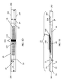
- FIG. 1A illustrates a perspective view of a delivery system for implanting an implant in a body.
- FIG. 1B illustrates a top view of a longitudinal section of one embodiment of a system for implanting an implant in a body.
- FIG. 1C illustrates a cross section at 1C-1C of the system for implanting an implant in a body, illustrated in FIG. 1A .
- FIG. 2A illustrates a top view of a longitudinal section of another embodiment of the system for implanting an implant in a body where drugs are absorbed by a surface coating on the inside of an envelope.
- FIG. 2B illustrates a cross section at 2B-2B of the system for implanting an implant in a body illustrated in FIG. 2A .
- FIG. 3A illustrates another embodiment of the longitudinal section of the system illustrated in FIG. 2A including apertures to permit the inside surface of the envelope to contact a drug solution and a tear feature.
- FIG. 3B illustrates a cross section at 3B-3B of the system for implanting an implant in a body illustrated in FIG. 3A .
- FIG. 4A illustrates a first side of a system for implanting an implant.
- FIG. 4B illustrates a second side of a system for implanting an implant.
- FIG. 4C illustrates the side view of a system for implanting an implant in a body including the first side illustrated in FIG. 4A and the second side illustrated in FIG. 4B .
- FIG. 4D illustrates a system for implanting an implant in a body including the first side illustrated in FIG. 4A and the second side illustrated in FIG. 4B .
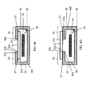
- FIG. 4E illustrates another embodiment of a system for implanting an implant in a body including the first side illustrated in FIG. 4A and the second side illustrated in FIG. 4B .
- FIG. 4F illustrates a cross section at 4F-4F of the system for implanting an implant in a body illustrated in FIG. 4E .
- FIG. 4G illustrates a cross section of another embodiment of a system for implanting an implant in a body including the first side illustrated in FIG. 4A and the second side illustrated in FIG. 4B .
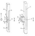
- FIG. 5A illustrates a side view of an embodiment of a system according to the invention including a clamp.
- FIG. 5B illustrates a side view of one embodiment of a clamp according to the invention.
- FIG. 5C illustrates a side view of another embodiment of a clamp according to the invention.
- FIG. 5D illustrates a top view of an embodiment of a system according to the invention including a clamp illustrated in FIG. 5A .
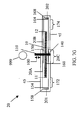
- FIG. 5E illustrates a side view of another embodiment of a system according to the invention for implanting an implant in a body including a bulk material disposed on the surface of the envelope.
- FIG. 5F illustrates a side view of another embodiment of a system according to the invention for implanting an implant in a body including a balloon on the surface of the envelope.
- FIG. 5G illustrates the system for implanting an implant in a body illustrated in FIG. 5F with the balloon filled.
- FIG. 5H illustrates an embodiment of the clamp illustrated in FIG. 5A including a filled balloon.
- FIG. 5I illustrates an embodiment of the clamp illustrated in FIG. 5A where the first member of the clamp includes a bulk material.
- FIG. 6 illustrates an embodiment of the system illustrated in FIGS. SF-SG for implanting an implant in a body.
- FIG. 7A illustrates another embodiment of the system for implanting an implant in a body.
- FIG. 7B illustrates the system shown in FIG. 7A including a surgical mesh.
- FIG. 7C illustrates the system shown in FIG. 7B .
- FIG. 7D illustrates a cross-section at 7D-7D of the embodiment of the system illustrated in FIG. 7C .
- FIG. 7E illustrates another embodiment of the system illustrated in FIG. 7C for implanting an implant in a body.
- FIG. 7F is a side view of another embodiment of the system for implanting an implant in a body.
- FIG. 7G illustrates another embodiment of the system illustrated in FIG. 7F for implanting an implant in a body.
- FIG. 8A illustrates one embodiment of a system for implanting an implant in a body.
- FIG. 8B illustrates a sleeve for use in the system illustrated in FIG. 8A for implanting an implant in a body.
- FIG. 8C illustrates another embodiment of the sleeve for use in the system illustrated in FIG. 8A for implanting an implant in a body.
- FIG. 8D illustrates another embodiment of the sleeve for use in the system illustrated in FIG. 8A for implanting an implant in a body.
- FIG. 8E illustrates another sleeve for use in the system illustrated in FIG. 8A for implanting an implant in a body.
- FIG. 8F illustrates making a system for implanting an implant in a body illustrated in FIG. 8A .
- FIG. 8G illustrates a top view of a system for implanting an implant in a body illustrated in FIG. 8A .
- FIG. 8H illustrates a side view of the system for implanting an implant in a body illustrated in FIG. 8A .
- FIG. 8I illustrates another view of the system for implanting an implant in a body illustrated in FIG. 8H .
- FIG. 8J illustrates another embodiment of the sleeve illustrated in FIG. 8D .
- FIG. 8K illustrates another embodiment of the system for implanting an implant in a body illustrated in FIG. 8G .
- FIG. 9A illustrates another embodiment of the system for implanting an implant in a body illustrated in FIG. 8A , where the implant is a sling.
- FIG. 9B illustrates another embodiment of the system for implanting an implant in a body illustrated in FIG. 9A .
- FIG. 9C illustrates another embodiment of the system for implanting an implant in a body illustrated in FIG. 9A .
- FIG. 9D illustrates another embodiment of the system for implanting an implant in a body illustrated in FIG. 9A .
- FIG. 9E illustrates another embodiment of the system for implanting an implant in a body illustrated in FIG. 8G .
- FIG. 10A illustrates one embodiment of a system for implanting an implant in a body.
- FIG. 10B illustrates a sleeve for use in the system illustrated in FIG. 10A for implanting an implant in a body.
- FIG. 10C illustrates a sleeve for use in the system illustrated in FIG. 10A for implanting an implant in a body.
- FIG. 10D illustrates a sleeve for use in the system illustrated in FIG. 10A for implanting an implant in a body.
- FIG. 10E illustrates a sleeve for use in the system illustrated in FIG. 10A for implanting an implant in a body.
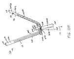
- FIG. 10F illustrates another embodiment of a system for implanting an implant in a body illustrated in FIG. 10A , where the implant is a sling.
- FIG. 11A illustrates an embodiment of the attachment piece according to the invention.
- FIG. 11B illustrates an embodiment of an implant secured to the attachment piece illustrated in FIG. 11A .
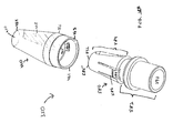
- FIG. 11C illustrates a perspective view of an embodiment of an implant-delivery member such as an attachment piece for delivering an implant to a body.
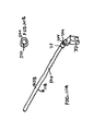
- FIG. 11D illustrates a side view of the embodiment of FIG. 11C .
- FIG. 11E illustrates a top plan view of the embodiment of FIG. 11C .
- FIG. 11F illustrates a bottom plan view of the embodiment of FIG. 11C .
- FIG. 11G illustrates a rear view of the embodiment of FIG. 11C .
- FIG. 11H illustrates a front view of the embodiment of FIG. 11C .
- FIG. 11I illustrates a perspective view of another embodiment of an implant-delivery member such as an attachment piece for delivering an implant to a body.
- FIG. 11J illustrates a side view of the embodiment of FIG. 11I .
- FIG. 11K illustrates a top plan view of the embodiment of FIG. 11I .
- FIG. 11L illustrates a bottom plan view of the embodiment of FIG. 11I .
- FIG. 11M illustrates a rear view of the embodiment of FIG. 11I .
- FIG. 11N illustrates a front view of the embodiment of FIG. 11I .
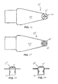
- FIG. 12A illustrates an embodiment of the dilator tube according to the invention.
- FIG. 12B illustrates another embodiment of the dilator tube illustrated in FIG. 12A .
- FIG. 13 illustrates an embodiment of the dilator tube and cannula according to the invention.
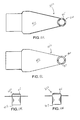
- FIGS. 14 - 17 illustrate an embodiment of the steps according to the method of the invention for seating and securing the attachment piece to the dilator tube.
- FIG. 18A illustrates another embodiment of the attachment piece according to the invention.
- FIG. 18B illustrates assembly of the attachment piece illustrated in FIG. 18A .
- FIG. 19A illustrates an embodiment of the deliveryassembly according to the invention.
- FIG. 19B illustrates a perspective view of an embodiment of a handle for delivering an implant to a body.
- FIG. 19C illustrates a front view of the embodiment of FIG. 19B .
- FIG. 19D illustrates a rear view of the embodiment of FIG. 19B .
- FIG. 19E illustrates a side view of the embodiment of FIG. 19B .
- FIG. 19F illustrates the opposing side view of the embodiment shown in FIG. 19E .
- FIG. 19G illustrates a top plan view of the embodiment of FIG. 19B .
- FIG. 19H illustrates a bottom plan view of the embodiment of FIG. 19B .
- FIG. 20A illustrates an embodiment of the dilator tube and bushing according to the invention.
- FIG. 20B illustrates a cross-section at 20B-20B of the embodiment of the dilator tube illustrated in FIG. 20A
- FIG. 20C illustrates an embodiment of the dilator tube illustrated in FIG. 19A in an extended position from the handle.
- FIG. 20D illustrates an embodiment of the dilator tube illustrated in FIG. 19A with the dilator tube in a retracted position in the lumen of the handle.
- FIG. 20E illustrates an embodiment of the dilator tube illustrated in FIG. 13 .
- FIG. 21A illustrates an embodiment of the cannula according to the invention.
- FIG. 21B illustrates a cross-section at 21B-21B of the embodiment of the cannula illustrated in FIG. 21C .
- FIG. 21C illustrates an embodiment of the cannula with the dilator tube retracted.
- FIG. 22A illustrates an embodiment of the retractable point according to the invention.
- FIG. 22B illustrates a cross-section of the retractable point according to the invention.
- FIG. 22C illustrates the retractable point, illustrated in FIG. 22A , extended from the cannula.
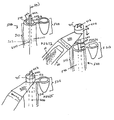
- FIG. 23A illustrates two positions of an embodiment of the proximal and distal buttons and two positions of the cannula retractor button on the handle according to the invention.
- FIG. 23B illustrates three positions of an embodiment of the proximal and distal buttons and two positions of the cannula notch and two positions of the cannula retractor button on the handle according to the invention.
- FIG. 23C illustrates another embodiment of the cannula notch illustrated in FIG. 23B .
- FIG. 23D illustrates an embodiment of an implant with a coupling ring.
- FIG. 23C illustrates another embodiment of an implant with a coupling ring.
- the invention described herein is a system for implanting an implant into the body of a patient.
- the system includes an implant 10, an envelope 20 enclosing the implant, an attachment piece 350 for attaching the envelope 20 or implant 10 to a delivery assembly 650, and a delivery assembly 650 for delivering the implant 10 to an anatomical site in the body of a patient.
- the delivery assembly 650 has a delivery handle 700, a dilator tube 500, and a cannula 600.
- the invention relates to an envelope for enclosing the implant.
- the envelope includes a therapeutic drug, such as an antibiotic, on the outer surface, the inner surface, or both the outer and inner surface of the envelope.
- the system includes an implant 10, for example, a surgical mesh or a surgical sling, surrounded by or enclosed within an envelope 20.
- the envelope 20 may be likened to a pouch or a sleeve that surrounds the mesh 10.
- the envelope 20 has a lumen 185, and the envelope 20 is, for example, a tube that encloses the mesh 10.
- the envelope 20 has an inner surface 30 and an outer surface 40.
- the width 24 of the envelope 20, as measured between the first side 203 and the second side 204 of envelope 20, may have a range from about 0.2 inches to 2.0 inches, preferably between about 0.5 inches and about 0.8 inches, and most preferably 0.6 inches.
- the longitudinal axis 22 of the envelope 20, measured from the first end 201 to the second end 202 of envelope 20, ranges from about 3.9 inches to about 27.6 inches, preferably between about 11.8 inches and about 23.6 inches, most preferably 19.7 inches.
- the first and second ends 201 and 202 are opened.
- the first and second ends 201 and 202 may be closed by, for example, a heat sealed bond.
- the implant is a surgical mesh 10.
- the surgical mesh 10 may be fabricated from one or more yarns and the yarns maybe made from one or more materials.
- Non-limiting materials that may be employed include polypropylene, polyesters, polyolefins, polytetrafluoroethylene, polyethylene, polyurethanes, nylons, and co-polymers thereof as described in U.S. Patent No. 6,042,592 , the disclosure of which is incorporated by reference herein.
- the surgical mesh 10 may be a hybrid of synthetic materials and tissues; the implant 10 may be directed to slings described in, for example, U.S.S.N. 09/916,983 , the entire disclosure of which is incorporated by reference herein.
- the surgical mesh 10 may also be made for absorbable materials, such as, polyglycolic acid, polylactic acid and other suitable absorbable materials.
- the yarn may include a plurality of filaments, alternatively, a monofilament yarn may be employed.
- the mesh is a polypropylene monofilament tricot mesh for use in surgical applications.
- each yarn may have void areas between yarn filaments.
- the process used to fabricate the mesh 10 may create crevices in the mesh 10.
- Multifilament yarns have multiple voids or interstitial spaces between the yarn filaments.
- Mesh 10, according to the invention may be produced according to a variety of fabrication processes known to the skilled artisan including, but not limited to, knitting, weaving, or braiding. Meshes fabricated using multifilament yarns may have both crevices and interstitial voids.
- the surgical mesh 10 is enclosed within the envelope 20 that surrounds the surgical mesh 10.
- the envelope 20 surrounding the mesh 10 reduces the likelihood that the mesh 10 will become contaminated with foreign matter such as bacteria during the procedure placing the mesh at an anatomical site in the body of the patient.
- the implant 10 is a sling, for example, the sling 10 described in U.S. patent application entitled “Medical Slings” by Gellman et al., attorney docket number (BSC-205), cofiled with the instant application, the entire disclosure of which is hereby incorporated by reference in its entirety.
- the longitudinal axis 13 of the sling 10 may range from about 3.9 inches to about 24.0 inches, or between about 15.7 inches to about 19.7 inches, preferably about 17.7 inches.
- the width 14 of the sling 10 is between about 0.39 inches and about 1 inch, preferably about 0.43 inches.
- the thickness 15 of the sling 10 ranges between about 0.0025 inch and about 0.1 inch, preferably between about 0.001 inch and 0.01 inch.
- the thickness of the material used to make the envelope 20 may range from about 0.0001 inch to about 0.01 inch, preferably 0.0003 inch thick.
- the envelope has a first side 21 and a second side 23 opposite to first side 21. The distance between the first side 21 and the second side 23 of envelope 20 ranges between about 0.0027 inches to about 0.12 inches.
- the envelope 20 may be used to assist in handling the sling 10 and/or to assist in adjusting the sling 10 during surgical placement.
- the envelope 20 aides in preventing the sling 10 from stretching or becoming misshapen due to the sling 10's handling prior to placement of the sling 10 at the anatomical site within the body of the patient.
- the invention provides a system for delivering the implant 10 having a drug delivery feature.
- the drug is delivered to the anatomical site in the patient's body and may be selected according to the physician's preference.
- Exemplary drugs are preferably soluble in water or other biologically inert solution, and include but are not limited to antimicrobials and antibiotics, such as neomycin and sulfa drugs, and anti-inflammatory agents such as steroidal or non-steroidal anti-inflammatory agents.
- the drug is released to the patient tissues upon contact with the tissues.
- the drugs that are delivered to the patient tissue surfaces when accessing and inserting the envelope 20 are active upon contact with the patient's tissue during implantation of the implant.
- the drug delivery system includes the envelope 20 that is made from one or more absorbent material such as, for example, a sponge-like material.
- the envelope 20 may be pre-soaked in a solution containing a drug such as an antibiotic prior to surgical implantation of the implant 10 in a patient's body. Soaking the envelope 20 in a solution containing the drug just prior to surgery, coats the outer surface 40 of the envelope 20 with the drug. Pre-soaking the envelope in a solution of the drug is advantageous because the inside of the patient's body tissues are wiped with the drug-coated envelope 20 when the envelope 20 is inserted into the patient's body during surgical implantation of the implant 10. Alternatively, the drug in the drug solution in which the envelope is soaked, penetrates the absorbent material and coats the inner surface 30 of the absorbent envelope 20.
- the envelope 20 is made from a non-wettable material such as polypropylene, polyethylene, polyester, polytetrafluoroethylene, TYVEK®, MYLAR®, or co-polymers thereof.
- Polytetrafluoroethylene is suitable for use in accordance with the present invention is available from DuPont (Wilmington, Delaware, under the trade designation TEFLON®). These non-wettable materials do not uptake any liquids, for example, solutions of drugs.
- the inner surface 30 and/or the outer surface 40 of the envelope 20 is pretreated with a substance that is wettable such as, for example, a wettable coating composition.
- the wettable coating composition may be a synthetic coating such as, for example, polyvinylperilidone (PVP) or a natural coating such as, for example, collagen.
- the coating may be a physically absorbent material such as, for example, a cellulose sponge material.
- the wettable coating composition may be hydrophilic, which absorbs hydrophilic drugs. In one embodiment, the hydrophilic drug associates with the hydrophilic coating. Alternatively, a hydrophobic drug is disposed on an envelope 20, the envelope 20 including a hydrophobic coating. In some embodiments, a hydrophilic coating traps the hydrophobic drug on the surface of the envelope.
- a hydrophobic coating may be applied to one or more surfaces of the envelope 20.
- Hydrophobic coatings may be used in conjunction with hydrophobic drugs. Where the association between the hydrophobic coating of the envelope 20 and the drug is weak, the drug will be readily released to the tissue surface contacted by the envelope 20. Alternatively, a stronger association between the coating and the drug, i.e., a stronger bonding affinity, may provide a slower release of the drug.
- the coating applied to the surface of the envelope 20 may have an ionic charge.
- drugs having a complimentary charge will bond to the charged coating applied to the surface of envelope 20 when the coating and the drug are exposed to one another.
- the strength of bonding between the drug and the coating will influence how readily the drug is released from the surface of the envelope 20. Where the ionic bonding between the coating on the envelope 20 and the drug is weak, the drug will release more readily. Covalent bonding between the surface coating of the envelope 20 and the drug will diminish drug release.
- the inner surface 30 of the envelope 20 has an inner surface coating 35 and the outer surface 40 of the envelope 20 has an outer surface coating 45.
- the inner surface coating 35 and the outer surface coating 45 may be selected from synthetic and natural coatings.
- the synthetic or natural coatings may be selected from the group consisting of a hydrophilic agent, a hydrophobic agent, and a physically absorbent material, for example, a cellulose sponge material.
- only one of the surfaces of the envelope 20 is coated, for example only the inner surface 30 of envelope 20 is coated.
- the outer surface 40 of envelope 20 is coated.
- the envelope 20 with a coated surface may be dipped into a solution containing a drug, for example, a hydrophilic drug, just prior to surgery.
- the drug in solution bonds to the hydrophilic coating on envelope 20.
- the hydrophilic coating and the hydrophilic drug are mixed to form a single coating.
- the hydrophilic coating may be disposed on the outer surface 40, the inner surface 30, or both the outer surface 40 and the inner surface 30 of the envelope 20.
- the envelope contains a pre-loaded drug or drug and coating mixture.
- the envelope 20 is not coated, but when dipped into a drug solution just prior to the surgery the drug coats the surface of the envelope 20 and/or a sufficient amount of drug, for example, between about 0.5 ml to about 3 ml, is trapped within the envelope 20.
- the inner surface coating 35 of the envelope 20 may be hydrophobic.
- the hydrophobic coating is mixed with a drug that is also hydrophobic. Thereafter the premixed hydrophobic coating and hydrophobic drug combination mixture is disposed on the inner surface 30 of the envelope 20.
- FIG. 2B is a cross section of the embodiment of the system including an implant 10 illustrated FIG. 2A.
- FIG. 2B illustrates that inner surface coating 35 is disposed on the inner surfaces 30 of the first side 21 and the second side 23 of envelope 20, in another embodiment a drug and coating combination may dispose thereon.
- the outer surface 40 of the envelope 20 is coated with the hydrophobic coating and drug combination mixture.
- Hydrophilic coatings may be water soluble and suitable water soluble hydrophilic coatings are available from Boston Scientific Corp., Natick, MA, under the trade designations HydroPlus and HydroPass.
- Hyoscymine sulfate may be used in accordance with the invention that is available under the trade designation CYTOSPAZ from Polymedica (Woburn, MA).
- Ketrolac tromethamine is available under the trade designation Toradol from Roche Pharmaceuticals (Nutley, NJ).
- Hydrophilic drugs that may be employed in accordance with the invention include oxybutynin chloride, lidocaine, ketorolac, and hyoscymine sulfate. Suitable hydrophobic drugs include ibuprofen, ketoprofen, and diclofenac.
- Hydrophobic coatings that may be employed in accordance with the invention include polytetrafluoroethylene, silicon, and Pyrelene.
- one or more apertures 50 are introduced into the envelope 20.
- the apertures 50 may be for example, cuts or slits.
- the apertures 50 extend through the envelope 20 and are disposed through at least the first side 21 of the envelope 20.
- the apertures 50 are introduced on all sides of the envelope 20.
- the apertures 50 allow drug access to the inner surface 30 of envelope 20. For example, when the envelope 20 is soaked in a solution containing a drug, the drug enters the lumen 185 of the envelope 20 via the apertures 50 and associates with the inner surface coating 35.
- the outer surface 40 and inner surface 30 of the envelope 20 are coated with an ionic coating composition.
- the envelope 20 having apertures 50 is soaked in a solution containing a drug bearing a charge complementary to the charge of the ionic coating composition, both the outer surface coating 45 and the inner surface coating 35 bond with the drug.
- FIG. 3B shows that in one embodiment, the inner surface 30 of the first side 21 of the envelope 20 includes an inner surface coating 35 and the first side 21 outer surface 40 includes an outer surface coating 45.
- FIG. 3B also shows that the second side 23 of the envelope 20 inner surface 30 includes an inner surface coating 35 and the second side 23 outer surface 40 includes an outer surface coating 45.
- apertures 50 are present on at least the first side 21 of envelope 20.
- a drug contacts the inner surface 30 of the envelope 20 when it flows through the apertures 50 into the lumen 185 of envelope 20.
- the drug associates with the inner surface coating 35.
- the outer surface coating 45 bonds with the drug when, for example, the envelope 20 is submerged in a solution containing the drug.
- the one or more apertures 50 disposed on the envelope 20 are, for example, slits disposed through the envelope 20.
- the apertures 50 are disposed in the envelope 20 to provide an opening on envelope 20 to permit drugs to enter the lumen 185 of envelope 20 and contact the inner surface 30 of the envelope 20.
- the apertures 50 range in size from about 1/16 inch to about 1/4 inch in greatest dimension and permit fluid exchange in and out of the lumen 185 of the envelope 20.
- the material used to manufacture the envelope 20 is porous, for example, polytetrafluoroethylene or polyethylene material and may be stretched so that the pores measure about 1 micron or greater.
- the one or more apertures 50 may be disposed so as to permit a solution to flow into the lumen 185 of the envelope 20 but not flow out, i.e., a one way channel.
- the one or more apertures 50 disposed through the envelope 20 may be pores or slits. Such apertures 50 may range in size from about 1 micron to about 1/4 inch in largest dimension.
- a relatively large aperture 50 for example, between about 1/16 inch and about 1/4 inch in largest dimension enables the drug containing solution to readily enter into and contact the inner surface 30 of the envelope 20 when the envelope 20 is soaked in the solution containing the drug. Some of the solution also escapes from the envelope 20.
- the one ore more apertures 50 are too small, i.e. about 5 microns, to permit the solution to escape from the envelope 20.
- the envelope 20 may also include a tear feature 60.
- the tear feature 60 assists the operator in opening the envelope 20 for placement of the mesh 10 enclosed by the envelope 20 inside the patient's body.
- the tear feature 60 may be a series of perforations through the envelope 20. The series of perforations through the envelope 20 weakens the portion of the envelope 20 where the tears are disposed such that the tear feature 60 permits the operator to open the envelope 20 by applying minimal force to the envelope 20.
- the tear feature 60 is disposed about the entire perimeter of the envelope 20.
- the tear feature 60 may be disposed along only a portion of the perimeter of the envelope 20.
- the tear feature 60 perforations may double as the apertures 50 that permit the solution in which the envelope 20 is immersed to enter the lumen 185 of the envelope 20 and to contact the inner surface 30 of the envelope 20.
- the apertures 50 permit the drug solution to penetrate through the envelope 20 to the lumen 185 to contact the inner surface 30 of the envelope 20 when the envelope 20 is soaked in the drug solution.
- the tear feature 60 includes a material that may be easily torn open.
- easily torn materials include, but are not limited to, for example, a material with a molecular orientation such as a linear low density polyethylene or linear polytetrafluoroethylene (e.g. TEFLON®).
- the entire envelope 20 may be manufactured from these materials.
- only one or more portions of the envelope 20 are manufactured from such "tearable" materials and/or construction methods, i.e., sections comprising linear low density polyethylene and/or a series of perforations or apertures 50 over a region of the envelope.
- the tear feature 60 also includes an envelope 20 with tabs 188 and 198 that may be torn away, as described in detail below in accordance with, for example, FIGS. 8A-8K and 9A-9E .
- the tear feature 60 is a strip of material disposed about the entire perimeter of the width 24 of envelope 20. The strip of material may be positioned, for example, against the inner surface 30 of the envelope. This strip of material protrudes from one or more areas of the envelope 20 where it may be accessed and torn away, unraveling at least a portion of the perimeter of envelope 20.
- the envelope is a composite of two or more materials.
- the first side 21 of envelope 20 includes a first material and the second side 23 of envelope 20 includes a second material that is different from the first material.
- FIG. 4C illustrates a side view of an envelope 20 wherein the first side 21 includes a first material and the second side 23 includes a second material and the sides, 21 and 23, are aligned and coupled at a seam 27 to form envelope 20.
- the first material of the first side 21 of envelope 20 is selected from the group of tearable materials, that includes, for example, polypropylene, nylon, a material with a molecular orientation such as a linear low-density polyethylene or other available flexible films.
- the second material on the second side 23 of envelope 20 may be a material that does not tear, for example, polytetrafluoroethylene, TYVEK®, MYLAR® or other materials such as, for example, thermoplastics.
- the composite envelope 20 may be formed of two different materials that do not tear, for example, a first side 21 having TYVEK® and a second side 23 having MYLAR®.
- the composite envelope 20 may be formed of two materials that tear, such as a first side 21 of polyethylene and a second side 23 of polypropylene.
- FIG. 4A illustrates a first side 21
- FIG. 4B illustrates a second side 23 of the envelope 20 illustrated in FIG. 4C
- width 241 of the first side 21 measured from the upper side 931 to the lower side 941 ranges from about 0.2 inches to about 2.0 inches, or between about 0.5 inches and about 0.8 inches and, preferably, 0.6 inches.
- the longitudinal axis 221 of the first side 21, measured from the first end 911 to the second end 921, as illustrated in FIG. 4A ranges in length from about 3.9 inches to about 27.6 inches, or between about 11.8 inches and about 23.6, preferably 19.7 inches. Referring again to FIG.
- the first side 21 and the second side 23 of the envelope 20 may be cut to the same dimensions and the first side 21 may be placed on top of and aligned with the second side 23.
- the first side 21 upper side 931 and the second side 23 upper side 932 are adjacent (not shown)
- the first side 21 lower side 941 and the second side 23 lower side 942 are adjacent
- the first side 21 first end 911 and the second side 23 first end 912 are adjacent
- the first side 21 second end 921 and the second side 23 second end 922 are adjacent.
- An envelope 20 may be formed by, for example, heat bonding around the perimeter of the aligned first side 21 and second side 23, to form seam 27 around the four sides of the aligned first side 21 and second side 23.
- a first seam (not shown) is formed between the first side 21 upper side 931 and the second side 23 upper side 932 and a second seam 27 is formed between the first side 21 lower side 941 and the second side 23 lower side 942, thereafter the interior of envelope 20 includes a lumen 185 with an open first end 201 and an open second end 202.
- the second side 23 that is adjacent to the first side 21 may include a melt liner.
- a melt liner is a layer or a portion of a layer that when added to the first side 21 and/or the second side 23 aids in forming the seam 27 between the first side 21 and the second side 23, when, for example, the sides 21 and 23 are exposed to a desirable temperature range.
- Suitable melt liners that may be employed include, for example, low density polyethylene, polyurethane, and polyester.
- the second side 23 includes a material that cannot tear, for example, TYVEK®.
- the first side 21 and the second side 23 are coupled with an adhesive to form seam 27.
- Suitable adhesives include, for example, urethane based and polyester based (i.e., elastomeric) adhesives.
- seam 27 forms the tearable region of the composite envelope 20.
- the second side 23 is larger in dimension than the first side 21.
- the dimensions of the second side 23 width 242 measures about 0.8 inches and the second side 23 longitudinal axis 222 measure about 27.6 inches.
- the dimensions of the first side 21 width 241 measures about 0.5 inches and the longitudinal axis 221 measures about 27 inches.
- the first side 21 has a top side 21a and a bottom side 21b (not shown) and the first side 21 is placed on top of the second side 23. In another embodiment, the first side 21 is placed in the center of the second side 23.
- the second side 23 has a top side 23a and a bottom side 23b.
- FIG. 4E and 4F shows that a portion of the excess material along the width 242 of the second side 23, shown in FIG. 4D , is folded to lie on the top side 21 a of the first side 21.
- the folded portion 26 of the upper side 932 of the second side 23 is coupled to the top side 21 a of the first side 21 to form a first seam 27, and the folded portion 26 of the lower side 942 of the second side 23 is also coupled to the top side 21a of the first side 21, to form a second seam 27.
- the folded portion 26 of the second side 23 folded on the top side 21a of the first side 21 includes adhesive, which couples the second side 23 top side 23a to the first side 21 top side 21a, to form an envelope 20 having a lumen 185.
- the second side 23 top side 23a that is adjacent to the first side 21 top side 21a, contains a melt liner.
- the melt liner joins the folded portions 26 of the second side 23 to the first side 21, by, for example, introducing heat to the folded portions 26 to bond the second side 23 to the first side 21 top side 21a, to form the seam 27.
- the first material of the first side 21 and the second material of the second side 23 are coupled by heat bonding in the folded portions 26, to form a seam 27.
- the first material of the first side 21 is tearable, i.e., a linear low density polyethylene, and the second material of the second side 23 is not tearable, for example, MYLAR®).
- the folded portion 26 of the second side 23 top side 23a is coupled to the first side 21 top side 21 a at the upper side 932, to form a first seam 27, and at the lower side 942 of the second side 23, to form a second seam 27.
- the first side 21 and the second side 23 form envelope 20, the envelope 20 having a lumen 185.
- the tearable material of the first side 21 coupled at about the upper side 932 and the lower side 942 of the second side 23 at folded portions 26, is torn at the seams 27 and separated from the second side 23.
- the tearable region may include the area of the envelope where a material that does not tear is coupled to a material that does tear.
- FIG.4G illustrates an embodiment where the first side 21 bottom side 21b is coupled to the second side 23 bottom side 23b at about the folded portions 26 to form a first seam 27 and a second seam 27 of envelope 20.
- first material on the first side 21 is not tearable and the second material on the second side 23 is tearable, the second side 23 tears at the seams 27 when the first side 21 is separated from the second side 23.
- the invention features an envelope 20 having a spacer 100, the envelope 20 enclosing the implant 10.
- the spacer 100 is a protrusion on at least one external surface of the envelope 20, having one or more pre-selected dimensions to aid in positioning the implant 10 at an anatomical site in the body of a patient.
- the envelope 20 encloses an implant 10 such as a mid-urethral sling 10.
- the spacer 100 is used to adjust the placement of the sling 10 inside the patient's body.
- the spacer 100 having pre-selected dimensions, is used to provide a reference distance between the envelope 20, which encloses the sling 10 and the patient's urethra 999.
- the operator is able to reference the relative distance between the envelope 20 surrounding the sling 10 and the patient's urethra 999 by the known pre-selected dimensions of the spacer 100.
- the operator may also adjust the sling 10 relative to the tension that is applied to the spacer 100.
- an envelope 20 including a tear feature 60 such as described in relation to FIGS. 3A-3B , also has a spacer 100, the spacer may provide tension adjustment.
- the tear feature 60 simplifies removal of the envelope 20 after the sling 10 is positioned.
- the spacer 100 illustrated in FIG. 5A is fastened around the perimeter of envelope 20.
- the spacer 100 is a clamp 110 that may be fastened around the envelope 20.
- the clamp 110 spacer 100 may be releasably coupled to the envelope 20.
- the clamp 110 has a first member 120 and a second member 130.
- the first member 120 has a proximal end 120a and a distal end 120b, and at least a first exterior face 121 extending therebetween and a first thickness 105.
- the clamp 110 also has a first interior face 122.
- the second member 130 has a proximal end 130a and a distal end 130b, and at least a second exterior face 131 extending therebetween and a second thickness 106.
- the proximal end 120a of the first member 120 and the proximal end 130a of the second member 130 are engageable such as by coupling, and the distal end 120b of the first member 120 and the distal end 130b of the second member 130 are engageable by coupling.
- the clamp 110 further includes a hinge 140.
- Hinge 140 of clamp 110 joins the first member 120 and the second member 130 of clamp 110.
- the proximal end 120a of first member 120 and the proximal end 130a of second member 130 couple by coupling mechanisms such as a tongue and groove, peg and hole, or other mechanisms for coupling known to the skilled person.
- the clamp 110 is sized to encircle the envelope 20.
- the length of the first interior face 122 of the first member 120 of clamp 110 and the length of the second interior face 132 of the second member 130 of clamp 110 ranges from about 0.2 inches to 2.0 inches.
- the dimensions of interior face 122 of clamp 110 and interior face 132 of clamp 110 are selected in accordance with the dimensions of the envelope 20.
- the width 125 of the first member 120 and the width of the second member 130 of the clamp 110 may range between about 0.2 inches and about 0.8 inches, preferably between about 0.4 inches and about 0.6 inches.
- the length 127 of the first member 120 of the clamp 110 may range from about 0.2 inches to 2.0 inches.
- the thickness 105 of the first member 120 of clamp 110 may range between about 0.007 inches and about 0.12 inches.
- the spacer 100 includes the first member 120.
- the thickness 105 of the first member 120 of spacer 100 establishes the distance between the envelope 20 enclosing the sling 10 and the patients urethra 999 or the patients bladdemeck. Where the first member 120 is the spacer, the thickness 105 of spacer 100 may measure between about 0.007 inches and about 0.8 inches, preferably between about 0.2 inches to about 0.6 inches.
- the length of the first member 120 measured by the distance between the proximal 120a and distal ends 120b of the first member 120, may be sized to complement the length of the patients urethra 999, generally between about 0.2 inches and 1.2 inches.
- the spacer 100 may include a bulk material 112 disposed on the first side 21 of the envelope 20.
- the bulk material 112 may be, for example, polyethylene or a hydrogel, such as, sodium carboxymethylcellulose, phosphate buffered saline (PBS), or combinations thereof.
- PBS phosphate buffered saline
- the bulk material 112 may be disposed on the entire surface of the first side 21 of envelope 20.
- the bulk material 112 may be disposed on only a portion of the first side 21 of envelope 20.
- the bulk material 112 is disposed at the midpoint between the first end 201 and the second end 202 of the longitudinal axis of the first side 21 of envelope 20.
- the bulk material 112 may be disposed between about 0.1 inches to about 0.4 inches, preferably between about 0.2 inches to about 0.3 inches to each side of the midpoint of the longitudinal axis.
- the bulk material 112 of the spacer 100 may be disposed across the width 24 of the first side 21 of the envelope 20, i.e., between the top side 203 and the bottom side 204 of the envelope 20.
- the width 24 of the envelope 20 is adjacent the urethra 999 or the bladdemeck.
- a spacer 100 provides a reference distance between the envelope 20 and the patient's urethra 999 or the patient's bladdemeck.
- the bulk material 112 should be disposed about between about 0.2 inches to about 1.2 inches along the width 24 of envelope 20, because the spacer 100 should be equal to or smaller than the length of the female urethra, and generally, the maximum length of the female urethra is 1.2 inches.
- the thickness 103 of the bulk material 112 disposed on the first side 21 may range from about 0.007 inches to about 0.8 inches, preferably between about 0.2 inches to about 0.6 inches.
- the spacer 100 includes a balloon 111.
- the balloon 111 is part of and integral with the envelope 20.
- the spacer 100, balloon 111 is joined to the envelope, for example, by adhesives.
- the balloon 111 is positioned on the inner surface 30 of the first side 21 of envelope 20. In another embodiment, the balloon 111 is positioned on the outer surface 40 of the first side of envelope 20. The balloon 111 may be disposed along the entire length of the first side 21 of envelope 20. Alternatively, as shown in FIGS. 5F-5G , the balloon 111 may be disposed on only a portion of the first side 21 of envelope 20.
- the longitudinal axis 107 of balloon 111 is between about 1.2 inches to about 4.0 inches about the midpoint of the longitudinal axis 22 of the envelope 20.
- the width 104 of the balloon 111 measures between about 0.4 inches to about 1.2 inches.
- the longitudinal axis 107 of balloon 111 is between about 0.2 inches to about 0.8 inches, preferably between about 0.4 inches and 0.6 inches, about the midpoint of the longitudinal axis 22 of the envelope 20, and the width 104 of the balloon 111 is between about 0.4 inches to about 1.2 inches.
- the width 104 of balloon 111 is equal to or smaller than the length of the female urethra, generally equal to or less than 1.2 inches. In another embodiment, the width 104 of the balloon 111 is the same as the width 24 of the envelope 20.
- the balloon 111 may be made from the same materials as the envelope 20. These materials include, but are not limited to, for example, an absorbent material, such as a sponge-like material, or polypropylene, polyethylene, polyester, polytetrafluoroethylene or copolymers thereof. Alternatively, the balloon 111 may be made of a different material than the material used to make the envelope 20. The balloon 111 may be placed on the envelope 20 according to methods known to the skilled person, for example, by gluing, sewing, tying, or melting onto a surface of envelope 20. In one embodiment, the balloon 111 is filled with a fluid or a gas and then joined to the exterior surface 40 of the first side 21 of the envelope 20. Alternatively, the balloon 111 may be filled with a gas or liquid after the balloon 111 is joined to the envelope 20. In yet another embodiment, the balloon 111 is integral with, i.e., fabricated in the envelope 20 when the envelope 20 is fabricated.
- an absorbent material such as a sponge-like material, or polypropy
- the balloon 111 may be filled with a gas or a fluid, for example, water, sterilized water, saline, or a bulk material such as, for example, polyethylene or a hydrogel, such as, sodium carboxymethylcellulose, PBS phosphate buffered saline, or combinations thereof.
- the balloon 111 may be filled to a thickness 103 between about 0.08 inches to about 0. 8 inches, preferably about 0.2 inches to about 0.6 inches.
- the extent of inflation of the balloon 111 may vary according to operator preference, the size of the patient, the anatomical location where the balloon is positioned, or other factors.
- the balloon 111 is filled by the operator prior to commencing the surgical procedure.
- the balloon 111 is filled after the envelope 20 enclosing the implant 10 is introduced into the anatomical site of the patient's body.
- the balloon 111 may be filled by inserting a needle coupled to a syringe into the balloon 111 and injecting the contents of the syringe, e.g., air, water, sterilized water, saline, bulk material, or a combination thereof, into the balloon 111.
- the balloon 111 may include a valve and the balloon is subsequently filled by injecting the contents of the syringe into the balloon 111.
- the balloon 111 is pre-filled and pre-attached to envelope 20.
- the clamp 110 includes a balloon 111 or a bulk material 112.
- the first exterior face 121 of the first member 120 includes a balloon 111.
- the thickness of spacer 100 includes a combination of the thickness 105 of the first member 120 and the thickness 103 of the balloon, bulk material, or other spacer device.
- the thickness of the spacer 100 includes the first member 120 thickness 105 and the balloon 111 thickness 103 or the first member 120 thickness 105 and the bulk material 112 thickness 103, respectively, as shown in FIGS. 5H and 5I .
- the spacer 100 thickness measures between about 0.007 inches to about 0.8 inches, preferably between 0.08 inches and 0.7 inches, preferably between about 0.2 inches to about 0.6 inches.
- the balloon 111 may be disposed on the first exterior face 121 of the first member.
- the bulk material 112 may be disposed on the first exterior face 121 of the first member 120.
- the balloon or bulk material entirely covers the first member 120 first exterior face 121.
- the spacer 100 is positioned adjacent to the urethra 999 or bladdemeck.
- the urethra length is generally up to 3 cm, about 1.2 inches.
- the balloon or the bulk material are positioned to cover between about 0.2 inches and about 1.2 inches of the length 127 of the first member 120 to form spacer 100.
- the balloon 111 and the bulk material 112 are positioned to cover between about 0.2 inch and about 0.8 inch of the width 125 of first member 120.
- the balloon 111 or the bulk material 112 covers the width 125 of the first member 120.
- the clamp 110 includes a pressure sensitive mechanism, i.e., a pressure sensor 101.
- the clamp 110 includes the pressure sensor 101 on the exterior face 121 of the first member 120.
- the first exterior face 121 of the first member 120 includes the spacer 100, such as, a balloon 111, and the pressure sensor 101.
- the pressure sensor 101 indicates the pressure applied to the spacer 100.
- the spacer 100 disposed on envelope 20 as shown in FIG. 5G includes the pressure sensor 101.
- the pressure sensor 101 is employed during the surgical procedure to measure and/or indicate the pressure applied to the urethra 999 or bladdemeck by the spacer 100.
- the spacer 100 is adjacent (i.e., disposed on or joined to) the envelope 20 enclosing the implant 10.
- tension is applied to the envelope 20 to adjust the distance between the urethra 999 or bladdemeck and the sling 10.
- a target pressure range may be set in the pressure indicator or pressure gauge.
- the pressure sensor 101 may be, for example, a tube that is connected at one end of the tube to the spacer 100 and at the other end of the tube to a pressure indicator.
- the pressure sensor 101 When the appropriate level of tension is applied to the spacer 100, the pressure sensor 101 indicates that the targeted pressure range is achieved.
- the pressure sensor 101 may indicate that this pressure is achieved by various indicator means, such as, for example, sound, digital readout, mechanical indicators, and fluid displacement (i.e., a manometer).
- various indicator means such as, for example, sound, digital readout, mechanical indicators, and fluid displacement (i.e., a manometer).
- a gap created by the spacer 100 is left between the sling 10 and the urethra 999 and there is no load present between the sling 10 and the urethra 999.
- the spacer 100 is a clamp 110 fastened around the permimeter of envelope 20, the clamp 110 is released from envelope 20 prior to removing the envelope 20 from the anatomical site in the patient's body.
- the envelope 20 and/or the clamp 110 are tinted. In one embodiment, only a portion of the envelope 20 is tinted, for example, about the longitudinal axis 22 of envelope 20.
- the envelope 20 and the clamp 110 may be the same color or alternatively, they may be tinted differently.
- a pattern or design is applied to on the envelope 20 and/or the clamp 110.
- the envelope 20 is tinted blue which is visible under the light from a cytoscope that is used when implanting the sling 10 into the body of the patient.
- the envelope 20 is tinted black.
- a spacer, a clamp, a tinted area or other indication mark provides a visual indication of the placement of the sling 10.
- the visual indication may be employed to inform the operator about the orientation of the sling 10, for example, whether the sling 10 is facing up, facing down or is twisted.
- the visual indication mark is on the center of the envelope 20 enclosing the sling 10.
- a visual indication of clamp 110 is aligned with the urethra 999.
- the envelope including a balloon 111 includes an outer surface coating 45 on the outer surface 40 of the envelope 20.
- a therapeutic drug may be associated such as, for example, bonded with the outer surface coating 45.
- the envelope 20 with the spacer 100 may further include one or more drugs and/or one or more coatings as described above (see FIGS. 1A , 1B , 2A, 2B , 3A, and 3B and corresponding text).
- the invention is a system for delivering an implant enclosed in an envelope.
- the envelope 20 has two or more sleeves 20A, 20B that are positioned such that one end of the first sleeve 20A overlaps an adjacent end of the second sleeve 20B.
- the two sleeves 20A, 20B enclose the implant 10.
- first sleeve 20A has a proximal end 154 including a tab 158 and a distal end 150.
- the tab 158 seals the proximal end 154 of the first sleeve 20A.
- the tab 158 is a positioning member for positioning the envelope 20 at the anatomical site in the body of the patient.
- the distal end 150 of first sleeve 20A is adjacent to the proximal end 160 of second sleeve 20B.
- the distal end 164 of second sleeve 20B includes a tab 168.
- tab 168 seals the distal end 164 of second sleeve 20B.
- the tab 168 is a positioning member for positioning the envelope 20 at the anatomical site in the body of the patient.
- first sleeve 20A measured from the distal end 150 to the proximal end 154, may range from about 2.0 inches to about 15.4 inches, preferably 11.0 inches.
- the length of second sleeve 20B measured from the proximal end 160 to the distal end 164, may range from about 2.0 inches to about 15.4 inches, preferably 11.0 inches.
- the first and second sleeves 20A and 20B are of equal length from their distal end to proximal end.
- FIG. 7B shows an implant 10, for example, a mid-urethral sling, a portion of which is placed into the distal end 150 of first sleeve 20A and a portion of which is placed into the proximal end 160 of second sleeve 20B.
- the length of the sling 10, i.e., the distance from the proximal end 11 to the distal end 12 of the sling 10, may range from about 4.0 inches to about 24.0 inches, or between about 16.0 inches to about 20.0 inches, preferably about 18.0 inches.
- FIG. 7C shows one embodiment of the envelope 20 including first sleeve 20A and second sleeve 20B enclosing the implant 10.
- the proximal end 160 of sleeve 20B is inserted into the distal end 150 of sleeve 20A to form an overlap region 20C of the first and second sleeves 20A, 20B.
- the overlap region 20C of first sleeve 20A and second sleeve 20B may range in length from about 0.4 inches to about 3.2 inches, preferably between 0.8 inches and 1.6 inches.
- FIG. 7D illustrates one embodiment of a cross section of region 20C of the envelope 20 where the proximal end 160 of second sleeve 20B is enclosed by the distal end 150 of first sleeve 20A.
- the length of the overlap region 20C, the length of the sling 10, and the length of first sleeve 20A and second sleeve 20B are selected to provide a section 172 of the sleeve 20A, from the proximal end 11 of the sling 10 to the proximal end of the 154 of sleeve 20A, that is at least 1 inch in length.
- section 174 of the sleeve 20B is at least inch in length.
- the sections 172 and 174 are grasped by the operator and assist in removal of the envelope 20 from the patient's body without disturbing the position of the implant of sling 10, as described below.
- the width 24 of the envelope 20 measured between the top side 203 and the bottom side 204 of envelope 20 may range from about 0.2 inches to about 2.0 inches, or between about 0.5 inches and about 0.8 inches, preferably 0.6 inches.
- the clamp 110 is used to fasten the sleeves 20A and 20B in the overlap region 20C such that the sleeves 20A and 20B are secured in place and the implant 10 remains inside the envelope 20.
- the clamp 110 is positioned and secured about the perimeter of the overlap region 20C of envelope 20.
- the first member 120 and the second member 130 of clamp 110 are closely aligned and positioned to provide enough compressive force to secure the region 20C and prevent separation of first sleeve 20A and second sleeve 20B during a procedure in which the envelope 20 is positioned at the anatomical site in the patient's body.
- the clamp 110 or other fastener releasably couples sleeves 20A and 20B and after the envelope 20 including clamp 110 is positioned in the patient's body, the clamp 110 is unfastened and removed. Thereafter sleeves 20A and 20B are removed and sling 10 remains positioned at the anatomical site in the patient's body.
- Alternative fasteners may be employed to secure the implant inside the sleeves of the envelope such as, for example, hemostats, needle graspers, and spring loaded clamps.
- FIG. 7F shows a sideview of the envelope 20 illustrated in FIG. 7E .
- the envelope 20 includes two sleeves 20A and 20B and a clamp 110.
- the clamp 110 is employed to couple the sleeves 20A and 20B, enclosing the implant 10.
- the proximal end 160 of sleeve 20B inside the distal end 150 of sleeve 20A forms overlap region 20C.
- the clamp 110 is placed around the perimeter of the overlap region 20C. In this view, a hinge 140 of clamp 110 is visible from the side view of the envelope 20.
- the invention includes a method for positioning the sling 10 at an anatomical site in a patient's body, for example, positioning a mid-urethral sling for the treatment of female urinary incontinence.
- the clamp 110 is placed at about the mid point of the sling 10, for example, as illustrated in FIGS. 7E and 7F .
- the physician may use the clamp 110 to indicate placement of the envelope enclosing the sling 10.
- the clamp 110 is positioned directly under the patient's urethra 999.
- the clamp 110 may further include the spacer 100. As described above, in relation to, for example, FIGS.
- the spacer 100 may include the thickness 105 of the first member 120 of clamp 110, alternatively or in addition, the thickness of the spacer 100 on the clamp 110 may include the thickness 103 of a balloon 111 or the thickness 103 of the bulk material 112.
- the operator may use the spacer 100 to adjust the tension of the sling 10 during its placement.
- the clamp 110 further includes a pressure sensor, for example, the pressure sensors 101 described above in conjunction with FIGS. 5B , 5F , 5G and 5H .
- the pressure sensor 101 is used by the operator to aid in positioning the sling 10 and applying the proper tension to the sling 10.
- the operator positions the envelope 20, shown in FIGS. 7E and 7F , including first sleeve 20A, and second sleeve 20B, the sling 10, and the clamp 110, at the anatomical site in the body of the patient.
- clamp 110 may be uncoupled, released from the envelope 20, and removed from the body of the patient. Thereafter, the operator may remove second sleeve 20B and first sleeve 20A from the body of the patient by grasping and pulling sleeve sections 174 and 172, respectively.
- first sleeve 20A and second sleeve 20B causes no change in sling 10 position.
- the placement and/or tension of the sling 10 remains the same as the placement and tension of the sling 10 when the operator placed the sling 10 at the anatomical site in the body, prior to removal of first sleeve 20A and second sleeve 20B.
- the envelope 20 including first sleeve 20A, second sleeve 20B, the sling 10, and the clamp 110 shown in FIG. 7G also includes an outer surface coating 45 disposed on the outer surface of envelope 20.
- the envelope 20 including sleeves 20A, 20B and the clamp 110 may further include one or more drugs and/or one or more coatings as described above (see FIGS. 1A , 1B , 2A, 2B , 3A, and 3B and corresponding text).
- the invention includes a system for delivering an envelope and an implant.
- the system includes the envelope 20 including two or more sleeves 20A, 20B and one or more tabs 188, 198, 208, 218.
- the tabs 188, 198, 208, and 218 simplify placement and/or removal of the envelope 20 from inside the body of the patient.
- the system includes an envelope 20 including the first sleeve 20A, the second sleeve 20B, tabs 188, 198 and an envelope hinge 200.
- the envelope 20 encloses the implant 10.
- FIG. 8B illustrates the first sleeve 20A of the envelope 20 shown in FIG. 8A .
- the first sleeve 20A includes an inner surface 30, an outer surface 40, a proximal end 154, and a distal end 150.
- the first sleeve 20A has a first lumen 185A.
- the length of the first sleeve 20A between the proximal end 154 and the distal end 150, along the longitudinal axis 22A, is between about 4.0 inches and about 28.0 inches, preferably about 20.0 inches.
- the perpendicular axis 24A of first sleeve 20A measures between about 0.2 inches to about 2.0 inches, preferably between about 0.4 inches and about 0.8 inches, preferably about 0.6 inches.
- two angles are cut into the first sleeve 20A, as indicated by the arrow 172 and arrow 174.
- the angles 172 and 174 are cut in the range of from about 20° to about 100°, or about 30° to about 70°, preferably about 60°, from the longitudinal axis 22A of the sleeve 20A illustrated in FIG. 8B .
- the two angles 172 and 174 are cut into the first sleeve 20A at a distance of between about 0.01 inch and about 0.05 inch, preferably about 0.04 inch.
- the distance cut into the first sleeve 20A is equivalent to the thickness of the sleeve 20A material.
- the angles 172 and 174 and the placement therefor may simplify tearing the envelope 20 with the tab 188, as described below, by, for example, providing a starting point for the tear.
- the distal end 150 portion of sleeve 20A is trimmed along the longitudinal axis 22A from the distal end 150 to angle 172 and from the distal end 150 to the angle 174.
- the amount of the first sleeve 20A that is trimmed along the longitudinal axis 22A from the distal end 150 to each respective angle is substantially the same.
- the distal end 150 portion has a top section 150A and a bottom section 150B as illustrated in FIGS. 8C and 8D .
- the longitudinal axis 22A of first sleeve 20A from the angle 174 to the end 150 of top section 150A may measure between about 2.0 inches to about 14.0 inches, preferably about 10.0 inches.
- the width of top section 150A is sized so that it is equal to or smaller then the inner diameter of a first lumen 185A of the first sleeve 20A of envelope 20. For example, the width of top section 150A may measure between about 0.1 inches and about 2.0 inches.
- a tab 188 may be joined to the end of top section 150A.
- the tab 188 may be shaped to complement the width of the end 150 of top section 150A.
- Tab 188 may include, for example, adhesive that is adhered to the end 150 of the top section 150A.
- the tab 188 may include a paperboard that is joined to the top section 150A by an adhesive, staple, heat bonding or other means known to the skilled person. It is contemplated that tab 188 may include various medical grade materials that may be joined to the top section 150A of first sleeve 20A, such as, for example TYVEK®.
- the end 150 of top section 150A may be shaped into a tab 188.
- the tab 188 may have a texture embossed on the material of sleeve 20A or 20B, or an additional layer of the sleeve 20A or 20B material may be joined to the end 150 to form tab 188.
- the additional layer may be tinted.
- the top section 150A coupled to tab 188, is pulled into a first lumen 185A of first sleeve 20A toward the proximal end 154 of first sleeve 20A.
- the width of top section 150A is preferably sized so that is equal to or smaller then the inner diameter of the first lumen 185A, so that sleeve 20A lays flat when the top section 150A is pulled inside the first lumen 185A.
- the top section 150A is not fully pulled into the sleeve 20A, such that an overlap region 150C of the top section 150A remains on the outer surface 40 of the first sleeve 20A.
- the overlap region 150C ranges between about 0.04 inches to about 1.2 inches, preferably about 0.3 inches.
- the length of the bottom section 150B, measured from the angle 172 and the angle 174 along the longitudinal axis 22A to the distal end 150 of the bottom section 150B, may measure between about 2.0 inches to about 14.0 inches, preferably about 10.0 inches.
- FIG. 8E illustrates the second sleeve 20B of the envelope 20 shown in FIG. 8A .
- the second sleeve 20B has an inner surface 30, an outer surface 40, a proximal end 160, and a distal end 164.
- the second sleeve 20B includes a second lumen 185B.
- the length of the second sleeve 20B between the proximal end 160 and the distal end 164, along the longitudinal axis 22B, is between about 4.0 inches and about 28.0 inches, preferably about 20.0 inches.
- the perpendicular axis 24B of second sleeve 20B measures between about 0.2 inches to about 2.0 inches, preferably between about 0.4 inches and about 0.8 inches, preferably about 0.6 inches.
- two angles represented by the arrow 172 and the arrow 174 are cut into the second sleeve 20B at the range of from about20° to about 100°, or about 30° to about 70°, preferably about 60°, from the longitudinal axis 22B of second sleeve 20B.
- the two angles 172 and 174 are cut into the second sleeve 20B at a distance of between about 0.01 inch and about 0.05 inch, preferably about 0.04 inch.
- the second sleeve 20B is trimmed along the longitudinal axis 22B from the proximal end 160 to the angle 172 and from the proximal end 160 to the angle 174.
- the amount of the second sleeve 20B that is trimmed along the longitudinal axis 22B from the proximal end 160 to each respective angle, 172 and 174, is substantially the same.
- the second sleeve 20B second lumen 185B includes a tube-like structure. After the tube-like second sleeve 20B is trimmed, the proximal end 160 includes a top section 160A and a bottom section 160B, as illustrated in FIG. 8E .
- the longitudinal axis 22B of second sleeve 20B from the angle 172 and the angle 174 to the end of top section 160B may measure between about 2.0 inches to about 14.0 inches, preferably about 10.0 inches.
- top section 160A is preferably sized so that is equal to or smaller then the inner diameter of the second lumen 185B, so that sleeve 20B lays flat when the top section 160A is pulled inside the second lumen 185B.
- the width of top section 160A may measure between about 0.1 inch and about 2.0 inches.
- a tab 198 is coupled to the end of top section 160A.
- the tab 198 may be shaped to complement the width of the end 160 of top section 160A and tab 198 may be constructed as described above with reference to tab 188.
- Top section 160A, coupled to tab 198, is pulled into the second lumen 185B of second sleeve 20B toward the distal end 164 of sleeve 20B.
- the top section 160A is not fully pulled into the second sleeve 20B, such that an overlap region 160C of top section 160A remains on the outer surface 40 of the second sleeve 20B.
- the overlap region 160C ranges between about 0.04 inches to about 1.2 inches, preferably about 0.3 inches.
- the length of bottom section 160B, measured from the angle 172 and the angle 174 along the longitudinal axis 22B to the proximal end 160 of the bottom section 160B may measure between about 2.0 inches to about 14.0 inches, preferably about 10.0 inches.
- the bottom section 150B of the first sleeve 20A is placed at about a 90° angle relative to the longitudinal axis 22A of the first sleeve 20A.
- the bottom section 160B of the second sleeve 20B is placed at about a 90° angle relative to longitudinal axis 22B of the second sleeve 20B.
- the sleeves 20A and 20B are aligned in proximity to one another such that the bottom sections 150B and 160B of sleeves 20A and 20B, respectively, face one another.
- the bottom sections 150B and 160B are joined to one another by adhesive, staples, heat bonding or other means known to the skilled person to form hinge 200.
- the proximal end 154 of first sleeve 20A and the distal end 164 of the second sleeve 20B are positioned on opposite ends of the envelope 20 formed by sleeve 20A and sleeve 20B.
- the bottom sections 150B and 160B of sleeve 20A and sleeve 20B form the hinge 200 of the envelope 20.
- the envelope 20 has a proximal end 154 and a distal end 164, formed by the proximal end 154 and distal end 164 of sleeve 20A and 20B, respectively.
- the length of envelope 20, measured along the longitudinal axis 22 from proximal end 154, which is equivalent to the first end 201, to distal end 164, which is equivalent to the second end 202 ranges between about 4.0 inches to about 28.0 inches, or between about 12.0 inches and about 24.0 inches, most preferably 20.0 inches.
- the overlap region 160C of sleeve 20B of envelope 20 may lay on top of the overlap region 150C of sleeve 20A of envelope 20.
- the length of overlap region 160C that is adjacent the remaining tube-like portion of the first sleeve 20A, i.e., 160C', may range between about 0.02 inches to about 0.06 inches, preferably 0.04 inches.
- the overlap regions protect the implant 10 inside of envelope 20, the envelope 20 including sleeves 20A and 20B.
- the overlap regions 150C and 160C of the envelope 20 prevents sling stretching caused by, for example, a hemostat used in the surgery.
- the angles represented by the arrow 212 and the arrow 214 are cut into the proximal end 154 of first sleeve 20A, and sleeve 20A is trimmed substantially as illustrated to form a narrow portion at the end of sleeve 20A.
- the proximal end 154 has a top section 154A and a bottom section 154B (not shown). The top section 154A and the bottom section 154B are separated from one another.
- the longitudinal axis of first sleeve 20A from the angle 212 to the proximal end 154 of top section 154A may measure between about 0.6 inches to about 4.0 inches, preferably between about 1.2 inches and about 2.0 inches.
- the perpendicular axis of top section 154A may measure between about 0.1 inch and about 2.0 inches.
- the perpendicular axis of top section 154A is equal to the width of the top section 150A of sleeve 20A, this enables the top section 150A to easily tear apart from the envelope. Referring to FIGS.
- a tab 208 may be used to join the proximal top section 154A and the proximal bottom section 154B.
- the tab 208 may include adhesive tape, glued paperboard, or other materials, as described above with reference to tab 188, that are capable of coupling together the top and bottom sections, 154A and 154B respectively.
- tab 188 may be accessed and pulled through this opening, while the tab 208 remains at the end 154 of sleeve 20A.
- the distal end 164 of sleeve 20B is trimmed at angles 212, 214 substantially as illustrated in FIG. 8J to form a narrow portion at each end of envelope 20.
- a distal top section 164A and a distal bottom section 164B are formed. Because the distal top section 164A and the distal bottom section 164B are separated, pulling the top section 160A coupled to tab 198 through the inner 30 surface of sleeve 20B through the second lumen of sleeve 20B toward the distal end 164 is simplified.
- a tab 218 is employed to couple the distal top section 164A and the distal bottom section 164B to one another.
- the tab 218 may be placed at the end 164 of sleeve 20B to leave an opening between the distal top and bottom sections, 154A and 164B, where tab 198 may be accessed and pulled.
- sleeves 20A and 20B are joined to form envelope 20.
- the first lumen 185A and the second lumen 185B form the single lumen 185 of the envelope 20.
- the joined bottom sections 150B and 160B of sleeves 20A and 20B form hinge 200 of envelope 20.
- Various methods may be employed to join bottom sections 150B and 160B, for example, heat bonding, adhesives, or staples.
- Alternative medical grade materials capable of coupling the sections together such as, for example, TYVEK® may be employed.
- the length of hinge 200 may range between about 2.0 inches to about 14.0 inches in length. The hinge 200 may be trimmed to a shorter length that may be grasped by the operator during the method of implanting the implant, described below in accordance with FIGS. 9B-9D .
- FIG. 9A illustrates one embodiment of the implant 10 positioned within the lumen 185 of the envelope 20.
- the overlap regions 150C and 160C cover the implant 10 enclosed within envelope 20.
- the implant 10 is placed within the envelope 20 after sleeves 20A and 20B are joined at hinge 200, but prior to tabs 208 and 218 being joined to the envelope 20.
- the implant for example a sling 10, may be manually inserted into lumen 185 of envelope 20.
- the sling 10 is placed within the first lumen 185A of the first sleeve 20A manually and/or with the aid of a grasping device.
- sleeve 20B is joined with sleeve 20A to form envelope 20, with the hinge 200.
- the remaining portion of sling 10 may be placed within the second lumen 185B of sleeve 20B prior to or after forming hinge 200.
- the invention includes a method for positioning the implant at an anatomical site in the body of a patient.
- the operator positions the envelope 20 enclosing sling 10, illustrated for example in FIG. 9A , at the anatomical site, for example, the urethra 999 or bladdemeck.
- the operator accesses the tab 208 coupled to proximal top section 154A of envelope 20.
- tab 208 coupled to the proximal end 154 is removed by the operator thereby uncoupling proximal top section 154A from the proximal bottom section 154B.
- the operator grasps hinge 200 and simultaneously pulls the tab 188 in the direction indicated by arrow 189.
- the force on tab 188 coupled to the top section 150A tears the envelope 20 along the top portion of the first sleeve 20A.
- the top section 150A of sleeve 20A is torn away from the envelope 20 in a single piece to expose the implant sling 10.
- Tab 188, the top section 150A, the top of sleeve 20A, and the proximal top section 154A are torn away from the envelope 20 and the implant sling 10 is exposed.
- the exposed portion of the sling 10 is adjacent the urethra 999.
- the distal end 164 coupled to tab 218 is similarly removed (not shown) and the distal top section 164A and the distal bottom section 164B are uncoupled.
- the operator grasps hinge 200 and simultaneously pulls tab 198.
- the force exerted on tab 198 coupled to the top section 160A tears these portions of sleeve 20B away from the envelope 20.
- tab 198, the top section 160A, the top of sleeve 20B, and the distal top section 164A are removed from envelope 20. The portion of the sling 10 previously enclosed is thereby exposed.
- the hinge 200 is removed along with the remainder of envelope 20, and the sling 10 remains inside the body of the patient at the anatomical site where the sling 10 was positioned by the operator, for example, at the anatomical site of the urethra 999.
- the sleeves 20A and 20B described in accordance with FIGS. 8D and 8E further include a cut 220A and a cut 220B disposed along the perpendicular axis of, the first sleeve 20A and the second sleeve 20B respectively.
- the cuts 220A and 220B may be disposed upon the top surface of sleeve 20A, 20B.
- the cut 220A may be sized so that it is equal to or longer then the perpendicular axis of the tab 188 and equal to or longer then the perpendicular axis of the top section 150A, enabling the tab 188 and top section 150A to be easily pulled through cut 220A.
- the tab 188 coupled to the top section 150A may be pulled through the cut 220A so that the tab 188 or the tab 188 and at least a portion of top section 150A is adjacent the outer surface 40 of envelope 20.
- the cut 220B may similarly be sized with respect to the perpendicular axis of the tab 198 and the top section 160A.
- the tab 198 coupled to the top section 160A may be pulled though the cut 220B so that the tab 198 or the tab 198 and at least a portion of top section 160A is adjacent the outer surface 40 of envelope 20.
- the tabs 188 and 198 are readily accessible from the proximal end 154 and the distal end 164 of envelope 20, the tabs 188 and 198 may be pulled to expose the implant 10 housed inside envelope 20 as described above with reference to FIG. 9D .
- the ends 154 and 164 do not need to be removed from envelope 20 prior to pulling the tabs 188 and 198.
- the invention provides an envelope 20 illustrated in FIG. 10A .
- the envelope 20 includes a sleeve 20C, and tabs 188 and 198, that are adjacent the outer surface 40 of the envelope 20.
- the sleeve 20C is provided, the longitudinal axis 22C of sleeve 20C, from the first end 201 to the second end 202, measures from about 12.0 inches to about 84.0 inches in length, and is preferably about 50.0 inches in length.
- the sleeve 20C width 24C as measured between the side 203 and the side 204, may have a range from about 0.2 inches to about 2.0 inches, preferably between about 0.5 inches and about 0.8 inches in length, and most preferably 0.6 inches.
- Sleeve 20C includes a lumen 185.
- sleeve 20C includes a top side 234 and a bottom side 236.
- a cut 220C is made about perpendicular to the longitudinal axis 22C of sleeve 20C.
- Cut 220C has a first side 221C and a second side 222C.
- the length of cut 220C, measured from the first side 221C to the second side 222C, is preferably equal to or less then the width of sleeve 20C. In some embodiments, cut 220C ranges from approximately 0.2 inches to about 2.0 inches in length.
- a diagonal cut 224 may be made through the bottom side 236 of sleeve 20C. Cut 224 has a top side 225 and a bottom side 226.
- the diagonal cut 224 is made at an angle of between about 85° and about 5°, preferably about 45° relative to cut 220C.
- the length between the diagonal cut 224 top side 225 and the first side 221C of cut 220C will vary according to the width 24C of sleeve 20C and the angle of diagonal line 224, in one embodiment this length ranges from about 0.1 inches to about 1.5 inches, and is preferably 0.3 inches.
- the distance between the diagonal cut 224 bottom side 226 and the second side 222C of cut 220C will similarly vary, and in one embodiment this length ranges from about 0.1 inches to about 1.5 inches, and is preferably 0.3 inches.
- diagonal cut 224 is perforated along its length.
- the first end 201 of sleeve 20C is trimmed to form a first top 201A and a first bottom 201B of sleeve 20C, such that where trimmed the lumen 185 has two separate pieces, 201A and 201B.
- the second end 202 of sleeve 20C is trimmed to form two separate pieces, namely, the second top 202A and second bottom 202B.
- the first top 201A is trimmed such that its width is equal to or less then the inner diameter of sleeve 20C, i.e. the lumen 185.
- the second top 202A is trimmed to a width that is equal to or less then the diameter of lumen 185.
- the free end of the first top 201A includes a tab 188.
- the free end of the second top 202A includes a tab 198.
- Tabs 188 and 198, that are connected to the first top 201A and the second top 202A respectively, may be constructed as described above with reference to tab 188 and FIG. 8C .
- the tab 188 joined to the end of the first top 201A is folded into the lumen 185 and laced through lumen 185.
- the tab 188 joined to the first top 201A are pulled through cut 220C, so that the tab 188 and/or a portion of the first top 201A is exposed on the outer surface 40 of sleeve 20C.
- the tab 198 joined to the end of the second top 202A is folded into the lumen 185 and laced through lumen 185. Thereafter, the tab 198 joined to the second top 202A is folded into lumen 185 and laced through lumen 185, where finally it is pulled through cut 220C, such that tab 198 and/or a portion of the second top 202A is also exposed on the outer surface 40 of sleeve 20C. After both tabs adjacent to top sections are laced through lumen 185 and pulled out cut 220C, the first top 201A is adjacent the second top 202A and both are enclosed within cut 220C. In one embodiment, as illustrated in FIGS.
- a diagonal cut 224 is placed on the sleeve 20C.
- the diagonal cut 224 may simplify lacing the tab 188 and first top 201A and the tab 198 and second top 202A through lumen 185 and into cut 220C.
- a single cut for example a diagonal cut 224 or a cut 220C, is disposed through only one side, i.e., either the top side 234 or the bottom side 236 of the sleeve 20C.
- a tab 208 is placed at the free end of the first bottom 201B, similarly, a tab 218 is placed at the free end of the second bottom 202B.
- the tabs 208 and 218 may be made of adhesive tape, glued paperboard, or other materials as described above with reference to tab 188 and FIG. 8C .
- the tabs 208 and 218 may be employed in positioning the envelope inside the body of a patient.
- FIG. 10F illustrates one embodiment of the implant 10 positioned within lumen 185 of the envelope 20, described above with reference to FIGS. 10A-10E .
- the envelope includes a material that is easily torn includes a material that is easily torn.
- Such easily torn materials are described above with reference to FIGS. 1A , 1B , 2A, 2B , 3A, and 3B and may include, for example, a material with a molecular orientation, such as a linear low density polyethylene.
- the implant 10 may be placed within lumen 185 of envelope 20 manually or with the aid of a grasping device. In one embodiment, the implant 10 is placed into the lumen 185 after both tabs 188 and 198 and/or both the first top 201A and the second top 202A are laced through cut 220C of sleeve 20C.
- the envelope 20 encloses the implant 10, for example, a mid-urethral sling.
- the invention includes a method for positioning the implant at an anatomical site in the body of a patient.
- the length of the first top 201A and the length of the first bottom 201B align to enable tabs 188 and 208 to lie about adjacent when envelope 20 lays flat.
- Eyelets or holes positioned through the first top 201A and the first botton 201B of envelope 20 align to form a coupling ring 355, described below with reference to FIGS. 23D and 23F, which may be attached to the delivery assembly 650 cannula 600 for implantation in the patient's body.
- eyelets positioned through the second top 202A and second bottom 202B align to form a coupling ring 355 that may be employed to implant the envelope 20 in the patient's body.
- the operator positions the envelope 20 enclosing sling 10 at the anatomical site, for example as illustrated in FIGS. 10A and 10F , the urethra 999.
- the bottom side 236 of the envelope 20 is adjacent the urethra.
- the tabs 188 and 198 and the associated portions of the first top 201A and the second top 202A, respectively, are visible from the patients vagina.
- the operator positions the tabs 208 and 218 so that they are on the external part of the patient's body, for example, the tabs 208 and 218 are external to the patient's pelvis or abdomen.
- the operator accesses the tab 188 joined to the first top 201A and tab 198 joined to the second top 202B, which are located in the area of the patients vagina.
- the operator grasps tab 188 coupled to the first top 201A and pulls the tab 188 in the direction of 190.
- the force on tab 188 coupled to the first top 201A tears a portion of the top side 234 of envelope 20.
- the operator grasps tab 198 coupled to the second top 202A and pulls the tab 198 in the direction of 190.
- the force on tab 198 coupled to the second top 202A tears the remaining portion of the top side 234 of envelope 20.
- the operator pulls the tab 208 to remove the bottom side 236 of envelope 20 from the body of the patient.
- the bottom side 236 may be split into two pieces, for example, in the area of diagonal cut 224, accordingly, in such cases both the tab 208 coupled to the first bottom 201B and the tab 198 coupled to the second bottom 202B will be pulled away from the direction of the patients body.
- the implant 10 longitudinal axis is at least equal to the length of the envelope 20.
- the implant 10 may be held within the envelope 20 by the tabs 208 and 218, for example, where the tabs are adhesive, the implant may be held within the envelope 20 by the tabs 208 and 218 disposed at each end of the envelope 20.
- the operator may uncouple the tabs 208 and 218, freeing implant 10. According to this method of the invention, the tabs 208 and 218 are uncoupled prior to removing the envelope 20 from the body of the patient.
- the invention in another aspect, relates to an attachment piece 350 for attaching the sling 10 or the envelope 20 enclosing the sling 10, to a delivery assembly 650.
- the attachment piece 350 includes a first member 400, such as a cylinder member 400.
- the cylinder member 400 of attachment piece 350 is engageable with a dilator tube member 500 of a delivery assembly 650, as described below.
- the cylinder member 400 is hollow having a least one lumen 418 and is substantially cylindrical surrounded by a wall 414.
- the cylinder member 400 further includes a first portion 410 at one end of the cylinder, and a second portion 420 at the opposite end of the cylinder.
- the height of cylinder member 400 is in the range of 0.1 to 1.0 inches, preferably 0.3 inches, and has an outer diameter in the range of 0.1 inches to 0.6 inches, preferably 0.19 inches.
- Cylinder member 400 is manufactured from materials such as, for example, polyethylene/ethylene vinyl acetate (EVA) blend, polyethylene, nylon, polypropylene, and thermoplastic FEP.
- EVA polyethylene/ethylene vinyl acetate
- the cylinder member 400 is divided into a first portion 410 at one end of the cylinder and a second portion 420 at the end opposite to the first portion 410.
- the length of the first portion 410 is 20-40% and the length of the second portion 420 at the opposite end of the cylinder is 60-80% of the total length of the cylinder member 400.
- an appendage 430 extends laterally outward from the wall 414 of the cylinder member 400 at the interface 412 of the first portion 410 of the cylinder member 400 and the second portion 420 of the cylinder member 400 as shown in FIG. 11A .
- cylinder member 400 further includes an appendage 430 which extends from the side of the cylinder member 400 at about one-third of the distance along the long axis of the cylinder member 400 from a first end 415 to a second end 417.
- Appendage 430 is substantially flat.
- the shape of appendage 430 permits appendage 430 to flex up or down, depending on which direction it is moved through the body of the patient.
- Appendage 430 conforms to the shape of the delivery assembly dilator tube when the cylinder member 400 is moved through the patient's tissue, described below.
- Appendage 430 is bonded, such as molded or otherwise securely attached, to the cylinder member 400.
- Appendage 430 measures in the range of about 0.2 to 1.0 inches in width and 0.5 to 2.0 inches in length, preferably, 0.6 inches by 1.0 inches.
- Materials used in the manufacture of appendage 430 include, but are not limited to, polyethylene/ethylene vinyl acetate blend, polyethylene, nylon, polypropylene, and thermoplastic FEP.
- the appendage 430 is manufactured from materials that are sufficiently flexible to pass through the patient's tissue without tearing, or otherwise traumatizing the tissue.
- the appendage 430 is bonded to the cylinder member 400 by an adhesive, heat sealing, or other means known to the skilled person. In one embodiment, the cylinder member 400 is heat bonded to the envelope 20 material.
- appendage 430 and cylinder member 400 are manufactured as a single piece, for example, by injection molding.
- a free end 435 of appendage 430 is attachable to the free end 436 of an envelope or sleeve 20 enclosing the implant 10, for example, an implantable sling 10 used for treatment of female urinary incontinence.
- the free end 435 of appendage 430 is attachable to, for example, a free end 434 of the implantable device 10.
- the free end 434 is bonded, or otherwise securely attached, to the cylinder member 400.
- the implantable device 10 is bonded, or otherwise securely attached, to the cylinder member 400.
- the implantable device 10 is not clamped, clipped, or pierced. Accordingly, the implantable device 10 other than being bonded to a member 400, is free to be manipulated in a plurality of planes when it is introduced into the patient's body.
- the free end 435 of the appendage 430 and the free end 436 of the envelope 20, are attached by, for example, heat bonding, suturing or adhesive bonding. If heat is used to bond the appendage 430 to the envelope 20, the glass transition range of the materials used to manufacture the appendage 430 and the envelope 20 must be similar to permit a satisfactory bond joint.
- the appendage 430 and the envelope 20 are manufactured from the same materials, for example, the material used to manufacture appendage 430 and envelope 20 may be polyethylene.
- a dilator tube 500 includes an elongated hollow member 510 and a tip 520, for example, a conical tip.
- the elongated hollow member 510 is 4.0 to 14.0 inches, preferably 8.0 inches in length, and 0.2 to 0.4 inches, preferably 0.25 inches, in outer diameter.
- the lumen of the elongated hollow member 510 is 0.1 to 0.7 inches in diameter, preferably 0.19 inches in diameter and is enclosed by tube wall 516.
- Tube wall 516 is 0.01 to 0.08 inches thick, preferably 0.03 inches.
- the hollow elongated member 510 terminates at end 560 where it abuts the conical tip 520.
- Materials used to manufacture dilator tube 500 include, but are not limited to, polyethylene, polypropylene, and nylon.
- the conical tip 520 is hollow and cone-shaped.
- the base 514 of the conical tip 520 is configured to abut the end 560 of the elongated hollow member 510.
- the conical tip 520 includes an aperture 402.
- the wall 516 of dilator tube 500 includes a cut 512 which is substantially perpendicular to the long axis of elongated hollow member 510 and is positioned near or substantially adjacent to the base 514 of the conical tip 520.
- the cut 512 forms the distal end 560 of the elongated member 510 and extends through nearly the entire circumference of the wall of dilator tube 500 but stops short of severing the conical tip 520 from the elongated hollow member 510 of the dilator tube 500. Accordingly, a flap 518 of wall 516 remains joining the conical tip 520 to the elongated member 510.
- the flap 518 thus acts as a hinge, as illustrated in FIG. 13 , permitting at least 90°, preferably 180° of articulation of the conical tip 520 relative to the long axis of the elongated member 510.
- Other means of attaching the conical tip 520 to the wall 516 other than those illustrated are also contemplated by the invention and are not limited to those illustrated.
- a cannula 600 is inserted into the lumen 540 of the elongated hollow member 510 of the dilator tube 500.
- the cannula 600 may be advanced in the lumen 540 of the hollow member 510 until the end 602 of the cannula 600 emerges from an opening 542 formed at the end of the elongated hollow member 510 substantially adjacent the hinge 518.
- the top 415 of the cylinder member 400 includes one or more slits 416 which extend through the top 415 into the lumen 418 of the cylinder member 400.
- the slits 416 through the top 415 of cylinder member 400 may be in the shape of an "X.”
- Embodiments of the slits 416 are not limited to those illustrated and may include, for example, Y-shape, V-shape, O-shape, or curvilinear.
- the top 415 of the cylinder has a conical shape, which is slit by the one or more slits 416.
- the shape of the top 415 and/or the slits 416 provide the cylinder member 400 with a shape that assures that there is one way to place the cylinder member 400 into the lumen 540 of dilator tube 500. Additional means or shapes that ensure one way placement of member 400 may be employed.
- the member 400 is shaped as a cylinder so that it mates with the lumen 540 of the hollow member 510 of dilator tube 500. Accordingly, other suitable mating dilator tube 500 lumen 540 and cylinder member 400 shapes may be selected, such as, for example, square, triangle, rectangle, or star.
- the slits 416 permit one-way assembly of cylinder member 400 over the cannula 600, described below.
- the second portion 420 of the cylinder member 400 is cylindrical in shape and hollow.
- the height of the second portion 420 is 0.07 to 0.7 inches, preferably 0.2 inches, or 2-3 times the height of the first portion 410 of the cylinder member 400.
- the dimensions of the second portion 420 are configured to enable the second portion 420 to be seated within the lumen 540 of the dilator tube 500, described below.
- the dimensions of the first portion 410 and the second portion 420 of cylinder member 400 may be configured to permit the cylinder member 400 to enter the lumen 540 of dilator tube 500 one way, i.e., so that the second portion 420 is inserted into the dilator tube 500 lumen 540.
- the free end 417 of the second portion 420 of cylinder member 400 has a chamfered edge to permit its ease of location in the lumen 540 of dilator tube 500.
- the cylinder member 400 attached by appendage 430 to an implant device such as the envelope 20 enclosing the sling 10, is introduced into the lumen 540 of the elongated member 510 of the dilator tube 500.
- the cylinder member 400 is seated into the lumen 540 of the elongated member 510 of dilator tube 500 thereby anchoring the cylinder 400 to the dilator tube 500.
- the cannula 600 is introduced from the lumen 540 of the dilator tube 500 into the lumen 418 of the hollow cylinder member 400 until the end 602 of the cannula 600 emerges from the top 415 of the cylinder member 400 through the slit 416 as illustrated in FIG. 15 .
- the conical tip 520 of the dilator tube 500 is rotated over the top of the first portion 410 of the cylinder member 400.
- the appendage 430 of the cylinder member 400 is trapped between the distal end 542 of the elongated member 510 of dilator tube 500 and the bottom 514 of the conical tip 520 of dilator tube 500.
- the conical tip 520 encloses the first portion 410 of the cylinder member 400 thereby joining the sling 10, or the envelope 20 and the sling 10, by the appendage 430 to the dilator tube 500 of the delivery assembly 650.
- the cannula 600 can be further extended through the slits 416 in the top 415 of the cylinder member 400, and through the aperture 402 at the end of conical tip 520.
- the conical tip 520 is fixed in position and can not move laterally thereby locking the sling 10 to the dilator tube 500 of the delivery assembly 650.
- the attachment piece 350 includes a cone 460 and a collet 580.
- the cone 460 is bonded to the implant 10 or envelope 20 by adhesive bonding, heat bonding, suturing, or any other bonding means known to the skilled person.
- the width 24 of the first end 201 of envelope 20 is heat bonded about a portion of the outer diameter of cone 460 at attachment site 466.
- width 24 of the first end 201 of envelope 20 covers about one half of the outer circumference of cone 460 at attachment site 466.
- the cone 460 and collet 580 are manufactured from materials such as polypropylene, nylon, acrylonitrile butadiene styrene (ABS), polycarbonate, preferably polyethylene or polyethylene/ethylene vinyl acetate blend to permit heat bonding to the sleeve.
- ABS acrylonitrile butadiene styrene
- the cone 460 and collet 580 may be manufactured by injection molding.
- the collet 580 is generally cylindrical, includes a lumen 590 and measures about 0.3 inches to 0.9 inches, preferably about 0.6 inches in length and 0.1 inches to 0.7 inches, preferably 0.3 inches in diameter at the widest point.
- a first end portion 582 of the collet 580, illustrated in FIG. 18A is a hollow cylinder and occupies about 25-50% of the length of the collet 580.
- the second end portion 584 of the collet 580, illustrated in FIG. 18A is tapered from the first end portion 582 to the second end 585 of the collet 580.
- the first end portion 582 of the collet 580 is inserted into the lumen 540 of the elongated hollow member 510 of the dilator tube 500 and bonded into the dilator tube.
- the cone 520 may be removed from the dilator tube 500.
- An aperture 592 is positioned at end 585 of the collet 580. The tapering of the collet 580 enables ease of passage through tissues in the patient's body when the attachment piece 350 is advanced without the cone 460 in place.
- a pair of cantilever locking tabs 586 are positioned on the outside surface of the tapered second portion 584 of the collet 580.
- the cantilever locking tabs 586 deflect inward when an exterior force is applied and the tabs 586 return to their original position to provide a snap engagement with a corresponding locking receptacle 462 on the cone 460, described below.
- a stabilizing bump 588 is provided on the cantilever locking tab 586 to stabilize the cantilever locking tabs 586 when the tabs 586 are engaged with the cone 460.
- the stabilizing bump 588 locks the collet 580 onto the cone 460.
- the cone 460 of the attachment piece 350 includes a substantially rectangular locking receptacle 462 positioned in the wall 463 in the lumen 465 side near the first end 461 of the cone 460.
- the cantilever locking tabs 586 in the collet 580 engage the locking receptacle 462 to secure the collet 580 to the cone 460.
- the number of locking receptacles 462 on the collet 580 are at least as many as the number of cantilever locking tabs 586 positioned on the cone 460.
- the locking receptacle 462 is a continuous receptacle (not shown) that encircles the wall 463 on the lumen 465 side of the cone 460.
- the cone 460 tapers from the cone first end 461 to a cone second end 464.
- an aperture 470 is positioned at the second end 464.
- the taper of the cone 460 parallels the taper of the second portion 584 of the collet 580.
- the similar tapers of the cone 460 and the second portion 584 of the collet 580 enable the second end 584 of the collet 580 to fit snugly within the lumen 465 of the cone 460.
- the cone 460 includes a surface 468 on the outside surface of the cone 460 for attachment of the implant 10 or sleeve 20.
- the second end portion 584 of collet 580 is introduced into the lumen 465 of the cone 460.
- the cantilever locking tabs 586 and stabilizing bump 588 fit into the corresponding locking receptacles 462 on the cone 460 to secure the collet 580 to the cone 460.
- the interface between the cone 460 and collet 580 must be sufficiently secure to withstand between about a 0.5 pound to about a 10 pound, preferably a four pound separation force.
- a cannula 600 may be introduced through the lumen 590 of the collet 580, the lumen 465 of the cone 460, the aperture 592 of the collet 580, and the aperture 470 of the cone 460.
- cannula 600 is sized to fit snugly inside lumen 590 of the collet 580.
- the presence of cannula 600 in lumen 590 of the collet 580 prevents locking tabs 586 from deflecting inward.
- the cannula 600 and the attachment piece 350 including the cone 460 and the collet 580 may be used to introduce the implant 10 or envelope 20 joined to the cone 460 into the body of the patient.
- the collet 580 With the collet 580 locked to the cone 460, the collet 580 can not be removed from the cone 460 without deflecting the locking tabs 586.
- the cone 460 provides a smooth transition from the leading cannula 600 to the dilatation feature of the collet 580.
- the cantilever tabs 586 With the cannula 600 inserted in the attachment piece 350, the cantilever tabs 586 are fully engaged in the receptacle 462 of the cone 460 locking the cone and collet of the attachment piece 350 together preventing the cantilever tabs 586 from deflecting until the attachment piece 350 is removed from the cannula 600.
- the cone 460 includes an orientation key to permit assembly of the cone 460 to a predetermined orientation on the collet 580 during assembly of the attachment piece 350.
- the invention is a method for attaching a medical device 10, such as a sling implant 10 for the treatment of female urinary incontinence, to a delivery assembly 650.
- a medical device such as a sling implant 10 for the treatment of female urinary incontinence
- the cylinder member 400 is pre-attached via appendage 430 to the implant 10 or to the envelope 20 enclosing the implant 10.
- An operator such as a physician, seats the second portion 420 of the cylinder member 400 into the lumen 540 of the elongated hollow member 510 of the dilator tube 500 to anchor the cylinder member 400 in the dilator tube 500.
- Conical tip 520 is rotated about hinge 518 until the conical tip 520 is seated over the first portion 410 of the cylinder member 400.
- the cannula 600 is advanced towards the top 415 of the cylinder member 400 until the end 602 of the cannula 600 emerges through slits 416 in the top 415 of the cylinder member 400.
- the cannula 600 is further advanced until the end 602 of the cannula 600 emerges through the aperture 402 in the conical tip 520.
- the delivery system 2 of the invention includes a delivery assembly 650.
- the delivery assembly 650 includes the dilator tube 500,the cannula 600, a retractable point 740, and a delivery handle 700.
- the retractable point 740 is operatively joined through the distal end 714 of the handle 700 to button 713 and button 715, described below, on the handle 700.
- the dilator tube 500 is operatively joined to an extender button 717 positioned on an elongated member 710 of the handle 700.
- handle 700 includes the elongated member 710 having a proximal end 712 that is furthest from the conical tip 520 of the dilator tube 500, and a distal end 714 that is closest to the conical tip 520 of the dilator tube 500.
- Elongated member 710 of the handle 700 has at least one lumen 709, illustrated in FIG. 20D , which parallels the long axis of the handle 700.
- Elongated member 710 is about 4.0 inches to 14.0 inches, preferably 8.0 inches in length and about 0.5 inches to 5.0 inches, preferably 1.5 inches in diameter.
- Handle 700 has a proximal button 713, a distal button 715, and an extender button 717.
- the proximal button 713 is positioned on the surface of the elongated member 710 at the proximal end 712 on one side of the handle 700.
- the distal button 715 is positioned on the elongated member 710 at the distal end 714 of the elongated member 710 on the same side of the handle 700 as the proximal button 713.
- the extender button 717 is positioned on a side other than the side of the handle 700 on which the proximal button 713 and distal button 715 are positioned. For example, referring to FIG.
- the extender button 717 is positioned on the side of the elongated member 710 of the handle 700 opposite to the side of the elongated member 710 on which the proximal button 713 and the distal button 715 are positioned.
- the extender button 717, proximal button 713, and the distal button 715 are positioned on the same side of the handle 700.
- the dilator tube 500 slides in and out of and extends outwardly from the distal end 714 of the elongated member 710 of the handle 700.
- the conical tip 520 of the dilator tube 500 is positioned at the distal end of the dilator tube 500.
- a bushing 724 is inserted into the proximal end 726 of the dilator tube 500.
- a cuff 718 is attached to the extender button 717 and rings the exterior of the proximal end 726 of dilator tube 500.
- extender button 717 and cuff 718 are manufactured as a single unit by, for example, injection molding.
- the bushing 724 is sized so that the dilator tube 500 fits snugly inside cuff 718.
- the bushing 724 maintains dilator tube 500 inside cuff 718 and retains dilator tube 500 inside the handle 700.
- the dilator tube 500 is manually slideably moveable by the extender button 717 from a first position, illustrated in FIG. 20C , in which the dilator tube 500 is in a first or extended position from the distal end 714 of the elongated member 710 of the handle 700, to a second or retracted position, illustrated in FIG. 20D , in which the proximal end 726 of the dilator 500 is withdrawn into the lumen 709 of the elongated member 710 of the handle 700 to a position substantially adjacent the proximal end 712 of the elongated member 710 of the handle 700.
- a rigid ring 523 is attached to the inside wall in the lumen 540 of the dilator tube 500 approximately 0.5 to 3.0 inches, preferably 1.3 inches from the end 542 of the elongated hollow member 510.
- the rigid ring 523 serves as a guide for passage of the cannula 600 in the lumen 540 of the dilator tube 500.
- more than one rigid ring 523 is present in the elongated member 510 of dilator tube 500 and/or within conical tip 520 of dilator tube 500.
- the rigid rings 523 guide and stabilize cannula 600 placement within the lumen of dilator tube 500 and the rigid ring 523 may be placed to direct cannula 600 into the center of dilator tube 500.
- the rigid rings 523 are tapered to an angle and become gradually flush with the inner diameter of the dilator tube 500 lumen, to assist in positioning cannula 600 within dilator tube 500.
- the rigid ring 523 is an insert such as a tubular insert that may be inserted into, for example, the elongated member 510 and/or the conical tip 520 of dilator tube 500.
- the outer diameter of such an insert may closely correspond to the inner diameter of the elongated member 510 in one embodiment, the outer diameter of the insert is about 0.2 inches and the inner diameter is about 0.14 inches.
- the insert is joined to the elongated member 510 by, for example, heat bonding.
- the cannula 600 is a second hollow elongated tube 604. The cannula 600 is inserted within the lumen 540 of the dilator tube 500, illustrated in FIG. 21B.
- the tube 604 of cannula 600 forms an arc from the cannula tip 602 at the distal end of the cannula 600, to about 10-75% of the length of tube 604.
- cannula 600 forms an arc with the concave surface of the arc on the same side of the cannula 600 as buttons 713 and 715 of the handle 700.
- the arc of the cannula 600 is selected to optimize the ease of insertion of the delivery system through the patient's tissues to position the implant 10 at the appropriate anatomical site.
- Cannula 600 is about 4.0 inches to about 14.0 inches, preferably 8.0 inches in length, and about 0.05 inches to about 0.3 inches, preferably 0.13 inches in diameter. Cannula 600 is approximately the same length as the dilator tube 500. In the most extended first position of dilator tube 500, substantially the entire length of the cannula 600 is surrounded by the dilator tube 500 as illustrated in FIG. 20C . When the dilator tube 500 is in its most retracted second position, approximately 20-50% of the cannula 600 is surrounded by the dilator tube 500 as illustrated in FIG. 21C . Cannula 600 is rigid and is manufactured from materials, such as stainless steel, plated carbon steel, or coated carbon steel.
- the retractable point 740 includes an elongated member 742 with a tapered end 744 at the distal end 741 of the elongated member 742.
- the elongated member 742 of the retractable point 740 is about 4.0 inches to about 14.0 inches, preferably 8.0 inches in length and 0.03 inches to about 0.1 inches, preferably 0.06 inches in diameter.
- the elongated member 742 of the retractable point 740 traces an arc corresponding to the arc of the cannula 600.
- the retractable point 740 is positioned in the lumen 610 of the cannula 600 as illustrated in FIG. 22B .
- the retractable point 740 is moveable from an extended first position illustrated in FIG. 22C to a retracted second position illustrated in FIG. 20C .
- the proximal button 713 and the distal button 715 on the handle 700 are each operatively joined to the retractable point 740 and are moveable through two positions, a first position A and second position B.
- first position A the tapered end 744 of the retractable point 740 is retracted into the cannula 600.
- the tapered end 744 of the retractable point 740 is extended from the distal end 602 of the cannula 600, for example, as illustrated in FIG. 22C .
- buttons 713 and 715 are spring biased to the first position from the second position requiring the operator to manually hold the button 713 or 715 to maintain the button in the second position to extend the tapered end 744 from the distal end 602 of the cannula 600.
- a projection 707, located under button 713 is pushed toward the distalend 714 of delivery handle 700, which moves bar 705 forward toward distal end 714.
- Retractable point 740 is housed inside bar 705 and is secured inside bar 705 by bolt 743.
- the portion of the cannula 600 near the distal end 602 of the cannula 600 includes a locking notch 615 to permit attachment of a coupling ring 355 to the cannula 600.
- the coupling ring illustrated in FIGS. 23D and 23F, is a loop attached to an end of the implant 10, or a hole or an eyelet positioned in the end of the implant 10, for coupling to the cannula notch 615.
- the loop may be formed by, for example, a suture or a wire, and a loop may be anchored to the end of the implant 10 by, for example, adhesive, heat sealing, being bolted to the end of the implant 10, being threaded through the implant 10, or by other available attachment means.
- a coupling ring 355 is positioned through one or more ends of an envelope 20 to permit joining the envelope 20 to the locking notch 615 of cannula 600.
- button 713 and button 715 have three position buttons, position A, position B and position C.
- position A of button 713 and button 715 the notch 615 is in the open, unlocked position ready to receive a coupling ring 355.
- position B of button 713 and button 715 the notch 615 is in the closed, locked position, as illustrated in FIG. 23C .
- position B the coupling ring 355 is locked in the notch.
- position C of button 713 and button 715 the retractable point 740 is extended from the distal end 602 of the cannula 600.
- Position C of the button 713 and button 715 is spring-biased to position B such that the operator must hold the button in position C to extend the retractable point 740.
- the cannula 600 or the distal end portion of the cannula 600 is detachable from the delivery assembly 650.
- Another aspect of the invention includes a method for delivering an implantable device 10 to an anatomical site in the body using the delivery assembly 650 according to the invention.
- An anatomical site includes, for example, the mid-urethra, prostate or neck of the urinary bladder.
- a transvaginal approach is used with the envelope 20 enclosing implant 10, such as , for example, a PINNACLE Sling manufactured by Boston Scientific Corporation, Natick, MA.
- the sling 10 is secured to the delivery assembly 650 by first bonding the sling 10 to the cylinder member 400 by heat bonding, adhesive or by other methods known to the skilled person.
- the dilator tube 500 is placed in the extended position illustrated in FIG.
- FIG. 20C by moving extender button 717 on the delivery handle 700 from position E to position D illustrated in FIG. 23A .
- the conical tip 520 of the dilator tube 500 is manually opened to the position illustrated in FIG. 20C (also see FIG. 11A ).
- the second portion 420 of the cylinder member 400 is seated in the lumen 540 of the hollow elongated member 510 of the dilator tube 500, as illustrated in FIGS. 14 and 15 .
- Conical tip 520 is manually rotated over the first portion 410 of the cylinder member 400, as shown in FIG. 16 .
- the sling 10 is attached by attachment piece 350 to the delivery assembly 650 as shown in FIG. 17 .
- the dilator tube 500 is moved from the extended position illustrated in FIG. 20C to the retracted position illustrated in FIG. 21C , by moving button 717 from position D to position E illustrated in FIG. 23A .
- the operator grasps the handle 700 and, in the transvaginal approach, advances the distal end 602 of the cannula 600 transvaginally to emerge through the rectus fascia, abdominal fasica and the abdominal wall in the region of the pubic tubercle of the patient.
- the dilator tube 500 is advanced over the cannula 600 by moving extender button 717 from the first position E to the second position D thereby advancing the dilator tube 500 distally over the cannula 600.
- the cannula 600 and dilator tube 500 are further advanced in the patient's tissues until the sling 10 extends through the rectus fascia.
- the sling 10 is disconnected from the attachment piece 350 by, for example, cutting, and the cannula 600 and dilator tube 500 are withdrawn from the patient. The procedure is repeated on the opposite side of the patient.
- the lumen 709 of delivery handle 700 has one or more locking regions in which dilator tube 500 may be locked in place as the operator moves dilator tube 500 from the first position E to the second position D.
- the operator may use both cannula 600 and dilator tube 500 to push through the rectus fascia, abdominal fascia and the abdominal wall when traversing from the vagina to the region to the pubic tubercle of the patient during the procedure.
- the sling 10 may be attached to the delivery assembly 650 prior to moving the dilator 500 and cannula 600 through the patient's tissue.
- the sling 10 may be attached to the delivery assembly 650 only after the tissue has been initially penetrated.
- the mid-urethra is approached percutaneously through the abdominal wall, abdominal fascia, and the rectus fascia rather than transvaginally as described above.
- the dilator tube 500 is advanced over the cannula 600 by moving extender button 717 on the handle 700 from first position E to the second position D.
- the extender button 717 is reversibly moveable through a plurality of positions from the first position E to the second position D.
- the proximal button 713 is moved from position A to position B to extend the tapered end 744 of the retractable point 740 beyond the distal end 602 of the cannula 600.
- the cannula 600 By firmly grasping the handle 700, the cannula 600, with retractable point 740 extended and dilator tube 500 extended, is advanced through the rectus fascia in the region of the pubic tubercle.
- the cannula 600 and dilator tube 500 are advanced until they emerge from an incision in the vaginal wall.
- the sling 10, attached to the attachment piece 350, is secured to the delivery assembly 650 as described above.
- the cannula 600 and dilator tube 500 with the attached sling 10 are pulled back into the incision until the sling 10 is placed in the correct position in the region of the mid-urethra. Once positioning of the sling 10 is confirmed, the sling 10 is disconnected from the attachment piece 350 and stabilized with forceps.
- the cannula 600 and the dilator tube 500 are withdrawn from the body. The same steps are repeated on the opposite side of the vagina.
- Another embodiment of the method for implanting an implant 10 at an anatomical site in the body of a patient includes the steps of providing an implant 10 enclosed in an envelope 20.
- the method further includes coating the envelope 20 with at least one drug, such as an antibiotic, on the inner surface, the outer surface, or both the inner and outer surface of the envelope.
- the method according to the invention may further include the step of providing a therapeutic drug dispersed on the envelope to the patients tissues.
- the method of the invention may further include the steps of positioning the implant 10 enclosed within the envelope 20 at the anatomical site in the body, and removing the envelope 20 while the implant 10 remains positioned at the anatomical site in the body of the patient.
- the method of the invention may further include tearing the envelope 20 at the tearable region 50 of the envelope 20, and removing the envelope 20 from the body.
- the method of the invention includes the step of providing a spacer 100 to position the implant 10 at the target anatomical site in the patient's body.
- the method may further include the step of measuring the tension applied to the sling 10 by a pressure sensor 101.
Landscapes
- Health & Medical Sciences (AREA)
- Life Sciences & Earth Sciences (AREA)
- General Health & Medical Sciences (AREA)
- Animal Behavior & Ethology (AREA)
- Engineering & Computer Science (AREA)
- Biomedical Technology (AREA)
- Heart & Thoracic Surgery (AREA)
- Veterinary Medicine (AREA)
- Public Health (AREA)
- Surgery (AREA)
- Urology & Nephrology (AREA)
- Cardiology (AREA)
- Oral & Maxillofacial Surgery (AREA)
- Vascular Medicine (AREA)
- Transplantation (AREA)
- Nuclear Medicine, Radiotherapy & Molecular Imaging (AREA)
- Medical Informatics (AREA)
- Molecular Biology (AREA)
- Prostheses (AREA)
- Materials For Medical Uses (AREA)
- Surgical Instruments (AREA)
Applications Claiming Priority (3)
| Application Number | Priority Date | Filing Date | Title |
|---|---|---|---|
| US27484301P | 2001-03-09 | 2001-03-09 | |
| US28686301P | 2001-04-26 | 2001-04-26 | |
| EP20020723361 EP1365688B1 (fr) | 2001-03-09 | 2002-03-07 | Systeme d'implantation d'une bandelette |
Related Parent Applications (1)
| Application Number | Title | Priority Date | Filing Date |
|---|---|---|---|
| EP02723361.8 Division | 2002-03-07 |
Publications (1)
| Publication Number | Publication Date |
|---|---|
| EP2292182A1 true EP2292182A1 (fr) | 2011-03-09 |
Family
ID=26957111
Family Applications (3)
| Application Number | Title | Priority Date | Filing Date |
|---|---|---|---|
| EP10180841A Withdrawn EP2292182A1 (fr) | 2001-03-09 | 2002-03-07 | Système d'implantation d'un implant |
| EP02723374A Expired - Lifetime EP1365679B1 (fr) | 2001-03-09 | 2002-03-07 | Echarpes medicales |
| EP07016188A Expired - Lifetime EP1913896B1 (fr) | 2001-03-09 | 2002-03-07 | Procède de fabrication d' une écharpe médicale |
Family Applications After (2)
| Application Number | Title | Priority Date | Filing Date |
|---|---|---|---|
| EP02723374A Expired - Lifetime EP1365679B1 (fr) | 2001-03-09 | 2002-03-07 | Echarpes medicales |
| EP07016188A Expired - Lifetime EP1913896B1 (fr) | 2001-03-09 | 2002-03-07 | Procède de fabrication d' une écharpe médicale |
Country Status (7)
| Country | Link |
|---|---|
| US (12) | US7235043B2 (fr) |
| EP (3) | EP2292182A1 (fr) |
| JP (4) | JP4298296B2 (fr) |
| AU (1) | AU2002254157B2 (fr) |
| CA (1) | CA2439212C (fr) |
| DE (1) | DE60223502T2 (fr) |
| WO (1) | WO2002071931A1 (fr) |
Cited By (1)
| Publication number | Priority date | Publication date | Assignee | Title |
|---|---|---|---|---|
| US12109099B1 (en) | 2020-09-04 | 2024-10-08 | Athena Surgical, LLC | Surgical implant delivery system and related methods |
Families Citing this family (451)
| Publication number | Priority date | Publication date | Assignee | Title |
|---|---|---|---|---|
| US6599235B2 (en) | 1997-03-18 | 2003-07-29 | American Medical Systems Inc. | Transvaginal bone anchor implantation device |
| US6039686A (en) | 1997-03-18 | 2000-03-21 | Kovac; S. Robert | System and a method for the long term cure of recurrent urinary female incontinence |
| US6382214B1 (en) * | 1998-04-24 | 2002-05-07 | American Medical Systems, Inc. | Methods and apparatus for correction of urinary and gynecological pathologies including treatment of male incontinence and female cystocele |
| US6478773B1 (en) | 1998-12-21 | 2002-11-12 | Micrus Corporation | Apparatus for deployment of micro-coil using a catheter |
| US8465494B2 (en) * | 1998-12-01 | 2013-06-18 | Atropos Limited | Apparatus for inserting a surgical device at least partially through a wound opening |
| US6835185B2 (en) * | 1998-12-21 | 2004-12-28 | Micrus Corporation | Intravascular device deployment mechanism incorporating mechanical detachment |
| US6602280B2 (en) | 2000-02-02 | 2003-08-05 | Trivascular, Inc. | Delivery system and method for expandable intracorporeal device |
| US7740637B2 (en) | 2000-02-09 | 2010-06-22 | Micrus Endovascular Corporation | Apparatus and method for deployment of a therapeutic device using a catheter |
| EP1665991B1 (fr) | 2000-06-05 | 2017-12-13 | Boston Scientific Limited | Dispositifs pour le traitment de l'incontinence urinaire |
| FR2811218B1 (fr) | 2000-07-05 | 2003-02-28 | Patrice Suslian | Dispositif implantable destine a corriger l'incontinence urinaire |
| US6638211B2 (en) * | 2000-07-05 | 2003-10-28 | Mentor Corporation | Method for treating urinary incontinence in women and implantable device intended to correct urinary incontinence |
| US7025063B2 (en) | 2000-09-07 | 2006-04-11 | Ams Research Corporation | Coated sling material |
| US6702827B1 (en) | 2000-10-06 | 2004-03-09 | American Medical Systems | Sling adjustment and tensioning accessory |
| US20060205995A1 (en) | 2000-10-12 | 2006-09-14 | Gyne Ideas Limited | Apparatus and method for treating female urinary incontinence |
| GB0025068D0 (en) | 2000-10-12 | 2000-11-29 | Browning Healthcare Ltd | Apparatus and method for treating female urinary incontinence |
| US8167785B2 (en) | 2000-10-12 | 2012-05-01 | Coloplast A/S | Urethral support system |
| AU2002217880A1 (en) * | 2000-11-15 | 2002-05-27 | Scimed Life Systems, Inc. | Device and method for treating female urinary incontinence |
| US6582443B2 (en) | 2000-12-27 | 2003-06-24 | Ams Research Corporation | Apparatus and methods for enhancing the functional longevity and for facilitating the implantation of medical devices |
| US7229453B2 (en) | 2001-01-23 | 2007-06-12 | Ams Research Corporation | Pelvic floor implant system and method of assembly |
| US6641525B2 (en) * | 2001-01-23 | 2003-11-04 | Ams Research Corporation | Sling assembly with secure and convenient attachment |
| US6802807B2 (en) | 2001-01-23 | 2004-10-12 | American Medical Systems, Inc. | Surgical instrument and method |
| US20020161382A1 (en) * | 2001-03-29 | 2002-10-31 | Neisz Johann J. | Implant inserted without bone anchors |
| US6612977B2 (en) | 2001-01-23 | 2003-09-02 | American Medical Systems Inc. | Sling delivery system and method of use |
| US7070556B2 (en) | 2002-03-07 | 2006-07-04 | Ams Research Corporation | Transobturator surgical articles and methods |
| US20020147382A1 (en) | 2001-01-23 | 2002-10-10 | Neisz Johann J. | Surgical articles and methods |
| DE10105592A1 (de) * | 2001-02-06 | 2002-08-08 | Achim Goepferich | Platzhalter zur Arzneistofffreigabe in der Stirnhöhle |
| US8915927B2 (en) | 2001-03-09 | 2014-12-23 | Boston Scientific Scimed, Inc. | Systems, methods and devices relating to delivery of medical implants |
| US9149261B2 (en) | 2001-03-09 | 2015-10-06 | Boston Scientific Scimed, Inc. | Systems, methods and devices relating to delivery of medical implants |
| US8033983B2 (en) * | 2001-03-09 | 2011-10-11 | Boston Scientific Scimed, Inc. | Medical implant |
| WO2002071931A1 (fr) * | 2001-03-09 | 2002-09-19 | Scimed Life Systems, Inc. | Echarpes medicales |
| US7364541B2 (en) | 2001-03-09 | 2008-04-29 | Boston Scientific Scimed, Inc. | Systems, methods and devices relating to delivery of medical implants |
| GB0108088D0 (en) | 2001-03-30 | 2001-05-23 | Browning Healthcare Ltd | Surgical implant |
| US6761733B2 (en) | 2001-04-11 | 2004-07-13 | Trivascular, Inc. | Delivery system and method for bifurcated endovascular graft |
| US6733521B2 (en) | 2001-04-11 | 2004-05-11 | Trivascular, Inc. | Delivery system and method for endovascular graft |
| US7037255B2 (en) | 2001-07-27 | 2006-05-02 | Ams Research Corporation | Surgical instruments for addressing pelvic disorders |
| US7407480B2 (en) | 2001-07-27 | 2008-08-05 | Ams Research Corporation | Method and apparatus for correction of urinary and gynecological pathologies, including treatment of incontinence cystocele |
| US20040073235A1 (en) * | 2001-10-01 | 2004-04-15 | Lund Robert E. | Surgical article |
| US6648921B2 (en) | 2001-10-03 | 2003-11-18 | Ams Research Corporation | Implantable article |
| US20100016943A1 (en) | 2001-12-20 | 2010-01-21 | Trivascular2, Inc. | Method of delivering advanced endovascular graft |
| US6911003B2 (en) | 2002-03-07 | 2005-06-28 | Ams Research Corporation | Transobturator surgical articles and methods |
| US7357773B2 (en) | 2002-03-07 | 2008-04-15 | Ams Research Corporation | Handle and surgical article |
| US8968178B2 (en) | 2002-03-07 | 2015-03-03 | Ams Research Corporation | Transobturator surgical articles and methods |
| WO2003075792A1 (fr) * | 2002-03-07 | 2003-09-18 | Ams Research Corporation | Articles chirurgicaux trans-obturateurs et procedes associes |
| AU2003229899A1 (en) * | 2002-04-11 | 2003-10-27 | Gyne Ideas Limited | Apparatus and method for treating female urinary incontinence |
| WO2003092546A2 (fr) * | 2002-04-30 | 2003-11-13 | Cook Urological Inc. | Bandelette de soutien de tissus |
| AU2003234212A1 (en) | 2002-05-07 | 2003-11-11 | Ams Research Corporation | Urethral prosthesis with tensioning member |
| USD534650S1 (en) | 2002-05-16 | 2007-01-02 | Ams Research Corporation | Handle for a surgical instrument |
| ES1058519Y (es) * | 2004-10-06 | 2005-04-01 | Maroto Jesus Romero | Malla para el tratamiento quirurgico de la incontinencia urinaria. |
| US8097007B2 (en) | 2002-08-02 | 2012-01-17 | C. R. Bard, Inc. | Self-anchoring sling and introducer system |
| US7371245B2 (en) | 2002-08-02 | 2008-05-13 | C R Bard, Inc | Transobturator introducer system for sling suspension system |
| US7637384B2 (en) * | 2002-08-09 | 2009-12-29 | Crown Packaging Technology, Inc. | Tamper evident closure with locking band and container therefor |
| CA2495314C (fr) * | 2002-08-14 | 2012-07-24 | Boston Scientific Limited | Implant medical |
| EP1531737B1 (fr) | 2002-08-14 | 2008-12-17 | Boston Scientific Limited | Systemes et dispositifs relatifs a la pose d'implants medicaux |
| EP1803415B1 (fr) * | 2002-08-14 | 2016-06-01 | Boston Scientific Limited | Implant médical |
| ES2287516T3 (es) * | 2002-09-19 | 2007-12-16 | Atropos Limited | Sistema retractor de herida. |
| US8317816B2 (en) | 2002-09-30 | 2012-11-27 | Acclarent, Inc. | Balloon catheters and methods for treating paranasal sinuses |
| USD543626S1 (en) | 2002-11-27 | 2007-05-29 | Ams Research Corporation | Handle for a surgical instrument |
| US6808486B1 (en) * | 2002-12-03 | 2004-10-26 | Pat O'Donnell | Surgical instrument for treating female urinary stress incontinence |
| CA2510570A1 (fr) | 2002-12-17 | 2004-07-22 | Boston Scientific Limited | Espaceur pour systeme de mise en place de d'attelle |
| US6893222B2 (en) * | 2003-02-10 | 2005-05-17 | United Technologies Corporation | Turbine balancing |
| EP3170459A1 (fr) | 2003-03-11 | 2017-05-24 | Covidien LP | Appareil d'application d'agrafes à mâchoire inclinée |
| GB0307082D0 (en) | 2003-03-27 | 2003-04-30 | Gyne Ideas Ltd | Drug delivery device and method |
| FR2852813B1 (fr) * | 2003-03-28 | 2005-06-24 | Analytic Biosurgical Solutions | Introducteur et guide perforateur pour la mise en place d'une bandelette dans le corps humain |
| US7494495B2 (en) | 2003-03-28 | 2009-02-24 | Coloplast A/S | Method and implant for curing cystocele |
| EP1610714A2 (fr) | 2003-03-28 | 2006-01-04 | Analytic Biosurgical Solutions - ABISS | Implant pour le traitement de la rectocele et dispositif pour la mise en place de cet implant |
| US20040199052A1 (en) | 2003-04-01 | 2004-10-07 | Scimed Life Systems, Inc. | Endoscopic imaging system |
| US7273448B2 (en) * | 2003-04-24 | 2007-09-25 | Ams Research Corporation | Male urethral prosthesis |
| US20040215054A1 (en) * | 2003-04-24 | 2004-10-28 | Siegel Steven W. | Male urethral prosthesis |
| WO2004096088A2 (fr) | 2003-04-25 | 2004-11-11 | Boston Scientific Limited | Systemes et methodes d'introduction et de mise en place de fronde |
| ITRM20030210A1 (it) * | 2003-04-30 | 2004-11-01 | Mauro Cervigni | Protesi da impiegarsi nella terapia chirurgica del prolasso |
| US7632291B2 (en) | 2003-06-13 | 2009-12-15 | Trivascular2, Inc. | Inflatable implant |
| US7361138B2 (en) * | 2003-07-31 | 2008-04-22 | Scimed Life Systems, Inc. | Bioabsorbable casing for surgical sling assembly |
| AU2003259832A1 (en) * | 2003-08-14 | 2005-03-10 | Boston Scientific Limited | Medical slings |
| US8545386B2 (en) | 2003-08-14 | 2013-10-01 | Boston Scientific Scimed, Inc. | Surgical slings |
| US20050038452A1 (en) * | 2003-08-14 | 2005-02-17 | Scimed Life Systems, Inc. | Medical slings |
| DE60327474D1 (de) * | 2003-08-14 | 2009-06-10 | Boston Scient Ltd | Medizinische schlinge |
| US8337386B2 (en) * | 2003-08-14 | 2012-12-25 | Boston Scientific Scimed, Inc. | Surgical slings |
| US7303525B2 (en) * | 2003-08-22 | 2007-12-04 | Ams Research Corporation | Surgical article and methods for treating female urinary incontinence |
| US7347812B2 (en) | 2003-09-22 | 2008-03-25 | Ams Research Corporation | Prolapse repair |
| AU2004279388B2 (en) * | 2003-10-03 | 2010-10-14 | Boston Scientific Limited | Systems for a delivering a medical implant to an anatomical location in a patient |
| US20050101834A1 (en) * | 2003-11-10 | 2005-05-12 | Merade Bryon L. | Readily implantable sling |
| US7261723B2 (en) * | 2003-11-12 | 2007-08-28 | Ethicon, Inc. | Surgical instrument and method for the treatment of urinary incontinence |
| WO2005048850A2 (fr) | 2003-11-17 | 2005-06-02 | Scimed Life Systems, Inc. | Systemes et procedes pour associer un implant medical a un dispositif de pose |
| US7922654B2 (en) | 2004-08-09 | 2011-04-12 | Boston Scientific Scimed, Inc. | Fiber optic imaging catheter |
| AU2005228956B2 (en) | 2004-03-23 | 2011-08-18 | Boston Scientific Limited | In-vivo visualization system |
| US11832793B2 (en) | 2004-03-23 | 2023-12-05 | Boston Scientific Scimed, Inc. | Vivo visualization system |
| WO2005094721A1 (fr) * | 2004-03-30 | 2005-10-13 | Proxy Biomedical Limited | Reseau chirurgical traite comprenant des fibres monofilaments |
| US7419497B2 (en) | 2004-04-21 | 2008-09-02 | Acclarent, Inc. | Methods for treating ethmoid disease |
| US7410480B2 (en) | 2004-04-21 | 2008-08-12 | Acclarent, Inc. | Devices and methods for delivering therapeutic substances for the treatment of sinusitis and other disorders |
| US9399121B2 (en) * | 2004-04-21 | 2016-07-26 | Acclarent, Inc. | Systems and methods for transnasal dilation of passageways in the ear, nose or throat |
| US7803150B2 (en) | 2004-04-21 | 2010-09-28 | Acclarent, Inc. | Devices, systems and methods useable for treating sinusitis |
| US9554691B2 (en) * | 2004-04-21 | 2017-01-31 | Acclarent, Inc. | Endoscopic methods and devices for transnasal procedures |
| US20070167682A1 (en) | 2004-04-21 | 2007-07-19 | Acclarent, Inc. | Endoscopic methods and devices for transnasal procedures |
| US8932276B1 (en) | 2004-04-21 | 2015-01-13 | Acclarent, Inc. | Shapeable guide catheters and related methods |
| US20060063973A1 (en) | 2004-04-21 | 2006-03-23 | Acclarent, Inc. | Methods and apparatus for treating disorders of the ear, nose and throat |
| US8702626B1 (en) | 2004-04-21 | 2014-04-22 | Acclarent, Inc. | Guidewires for performing image guided procedures |
| US9101384B2 (en) * | 2004-04-21 | 2015-08-11 | Acclarent, Inc. | Devices, systems and methods for diagnosing and treating sinusitis and other disorders of the ears, Nose and/or throat |
| US8764729B2 (en) | 2004-04-21 | 2014-07-01 | Acclarent, Inc. | Frontal sinus spacer |
| US7654997B2 (en) | 2004-04-21 | 2010-02-02 | Acclarent, Inc. | Devices, systems and methods for diagnosing and treating sinusitus and other disorders of the ears, nose and/or throat |
| US10188413B1 (en) | 2004-04-21 | 2019-01-29 | Acclarent, Inc. | Deflectable guide catheters and related methods |
| US8894614B2 (en) | 2004-04-21 | 2014-11-25 | Acclarent, Inc. | Devices, systems and methods useable for treating frontal sinusitis |
| US20190314620A1 (en) | 2004-04-21 | 2019-10-17 | Acclarent, Inc. | Apparatus and methods for dilating and modifying ostia of paranasal sinuses and other intranasal or paranasal structures |
| US8864787B2 (en) | 2004-04-21 | 2014-10-21 | Acclarent, Inc. | Ethmoidotomy system and implantable spacer devices having therapeutic substance delivery capability for treatment of paranasal sinusitis |
| US9351750B2 (en) | 2004-04-21 | 2016-05-31 | Acclarent, Inc. | Devices and methods for treating maxillary sinus disease |
| US7361168B2 (en) * | 2004-04-21 | 2008-04-22 | Acclarent, Inc. | Implantable device and methods for delivering drugs and other substances to treat sinusitis and other disorders |
| US20060004323A1 (en) | 2004-04-21 | 2006-01-05 | Exploramed Nc1, Inc. | Apparatus and methods for dilating and modifying ostia of paranasal sinuses and other intranasal or paranasal structures |
| US8747389B2 (en) | 2004-04-21 | 2014-06-10 | Acclarent, Inc. | Systems for treating disorders of the ear, nose and throat |
| US20070208252A1 (en) * | 2004-04-21 | 2007-09-06 | Acclarent, Inc. | Systems and methods for performing image guided procedures within the ear, nose, throat and paranasal sinuses |
| US7559925B2 (en) | 2006-09-15 | 2009-07-14 | Acclarent Inc. | Methods and devices for facilitating visualization in a surgical environment |
| US7462175B2 (en) | 2004-04-21 | 2008-12-09 | Acclarent, Inc. | Devices, systems and methods for treating disorders of the ear, nose and throat |
| US8146400B2 (en) | 2004-04-21 | 2012-04-03 | Acclarent, Inc. | Endoscopic methods and devices for transnasal procedures |
| US9089258B2 (en) | 2004-04-21 | 2015-07-28 | Acclarent, Inc. | Endoscopic methods and devices for transnasal procedures |
| US7500945B2 (en) | 2004-04-30 | 2009-03-10 | Ams Research Corporation | Method and apparatus for treating pelvic organ prolapse |
| US7811222B2 (en) | 2004-04-30 | 2010-10-12 | Ams Research Corporation | Method and apparatus for treating pelvic organ prolapse |
| US7351197B2 (en) | 2004-05-07 | 2008-04-01 | Ams Research Corporation | Method and apparatus for cystocele repair |
| US8439820B2 (en) * | 2004-05-06 | 2013-05-14 | Boston Scientific Scimed, Inc. | Systems and methods for sling delivery and placement |
| US8062206B2 (en) | 2004-05-07 | 2011-11-22 | Ams Research Corporation | Method and apparatus for treatment of vaginal anterior repairs |
| GB0411360D0 (en) | 2004-05-21 | 2004-06-23 | Mpathy Medical Devices Ltd | Implant |
| US20050278037A1 (en) * | 2004-06-11 | 2005-12-15 | Analytic Biosurgical Solutions-Abiss | Implant for the treatment of cystocele and rectocele |
| EP1765218B1 (fr) | 2004-06-14 | 2014-06-11 | Boston Scientific Limited | Bandelette implantable pour le traitement de l'incontinence urinaire |
| EP1778125B1 (fr) * | 2004-07-28 | 2012-05-23 | Ethicon, Inc. | Implant medical a effraction minimale, dispositif d'insertion et procede d'utilisation correspondants |
| US20060052800A1 (en) * | 2004-09-03 | 2006-03-09 | Secant Medical, Llc | Surgical tool for incontinence sling implantation |
| CA2580931C (fr) | 2004-09-23 | 2013-05-07 | Tyco Healthcare Group Lp | Dispositif d'application d'agrafes et agrafe de ligature |
| US7819886B2 (en) | 2004-10-08 | 2010-10-26 | Tyco Healthcare Group Lp | Endoscopic surgical clip applier |
| JP4783372B2 (ja) * | 2004-10-08 | 2011-09-28 | タイコ ヘルスケア グループ エルピー | 外科用クリップを付与するための装置 |
| JP5047799B2 (ja) | 2004-10-08 | 2012-10-10 | タイコ ヘルスケア グループ リミテッド パートナーシップ | 内視鏡外科用クリップ取付器 |
| US8500624B2 (en) * | 2004-10-25 | 2013-08-06 | Boston Scientific Scimed, Inc. | Systems and methods for sling delivery and placement |
| EP2198786B1 (fr) * | 2004-10-25 | 2011-11-23 | Boston Scientific Limited | Systèmes d'introduction et de mise en place de bandelette |
| US20060149121A1 (en) * | 2005-01-03 | 2006-07-06 | Hughett James D Sr | Instrument guide and method for use |
| US8029528B2 (en) * | 2005-01-03 | 2011-10-04 | Atricure, Inc. | Instrument guide and method for use |
| US20060173468A1 (en) * | 2005-01-28 | 2006-08-03 | Marc Simmon | Obturator introducer with snare |
| US20060241653A1 (en) * | 2005-02-04 | 2006-10-26 | Jones Daniel B | Surgical hook instrument for gastric band closing |
| US7914437B2 (en) | 2005-02-04 | 2011-03-29 | Ams Research Corporation | Transobturator methods for installing sling to treat incontinence, and related devices |
| ES2573672T3 (es) * | 2005-02-04 | 2016-06-09 | Boston Scientific Scimed Inc. | Diseño de aguja para sling transobturador masculino |
| US20060199996A1 (en) * | 2005-03-04 | 2006-09-07 | Ricardo Caraballo | Sling for supporting and occluding a tissue and method of using the same |
| US9364229B2 (en) | 2005-03-15 | 2016-06-14 | Covidien Lp | Circular anastomosis structures |
| US7942890B2 (en) * | 2005-03-15 | 2011-05-17 | Tyco Healthcare Group Lp | Anastomosis composite gasket |
| US20090204129A1 (en) * | 2005-03-22 | 2009-08-13 | Leslie Fronio | Bioactive wide-weave mesh |
| AU2006226961A1 (en) * | 2005-03-22 | 2006-09-28 | Tyco Healthcare Group, Lp | Mesh implant |
| US20060252993A1 (en) * | 2005-03-23 | 2006-11-09 | Freed David I | Medical devices and systems |
| WO2006108145A1 (fr) | 2005-04-06 | 2006-10-12 | Boston Scientific Scimed, Inc. | Systemes, dispositifs, et procedes de traitement de troubles du plancher pelvien |
| FR2884409B1 (fr) * | 2005-04-15 | 2009-10-02 | Sofradim Production Sa | Ensemble pour traitement chirurgical d'un prolapsus, par exemple cystocele ; et implant adapte pour un tel traitement |
| US20060281967A1 (en) * | 2005-04-22 | 2006-12-14 | Sofradim Production | Prosthetic safeguard for support implants |
| US7393320B2 (en) | 2005-04-29 | 2008-07-01 | Ams Research Corporation | Pelvic floor health articles and procedures |
| US20100016888A1 (en) * | 2005-05-05 | 2010-01-21 | Allison Calabrese | Surgical Gasket |
| US20100012703A1 (en) * | 2005-05-05 | 2010-01-21 | Allison Calabrese | Surgical Gasket |
| US8951225B2 (en) | 2005-06-10 | 2015-02-10 | Acclarent, Inc. | Catheters with non-removable guide members useable for treatment of sinusitis |
| WO2007002012A1 (fr) | 2005-06-21 | 2007-01-04 | Ams Research Corporation | Dispositif destine a la fixation d'une bandelette sous-uretrale a l'os pubien |
| WO2007002071A1 (fr) * | 2005-06-21 | 2007-01-04 | Ams Research Corporation | Appareil pour fixer une attelle urétrale à l'os pubien |
| CA2550752C (fr) * | 2005-06-28 | 2014-09-09 | Sherwood Services Ag | Dispositif tunnel d'ivs a eclairage |
| EP1909687A1 (fr) | 2005-07-13 | 2008-04-16 | Boston Scientific Scimed, Inc. | Système d ancrage en fronde à ajustement serré et procédés apparentés |
| BRPI0613622A2 (pt) * | 2005-07-21 | 2017-05-02 | Fmc Biopolymer As | dispositivo médico |
| WO2007014241A1 (fr) | 2005-07-25 | 2007-02-01 | Boston Scientific Scimed, Inc. | Systeme de reparation du plancher pelvien |
| CA2615130A1 (fr) | 2005-07-26 | 2007-02-08 | Ams Research Corporation | Procedes et systemes pour le traitement du prolapsus |
| WO2007018532A1 (fr) * | 2005-08-03 | 2007-02-15 | Boston Scientific Scimed, Inc. | Systèmes, appareils et méthodes concernant un support résistant en forme de fronde pour traiter l'incontinence urinaire |
| US20100241105A1 (en) * | 2005-08-04 | 2010-09-23 | C.R. Bard, Inc. | System for introducing implants |
| JP2009515564A (ja) | 2005-08-04 | 2009-04-16 | シー・アール・バード・インコーポレイテツド | 骨盤インプラントシステムおよび方法 |
| US7935046B2 (en) * | 2005-08-11 | 2011-05-03 | Boston Scientific Scimed, Inc. | Systems, methods and devices relating to a removable sleeve for an implantable sling |
| WO2007027592A1 (fr) * | 2005-08-29 | 2007-03-08 | Ams Research Corporation | Systeme de positionnement d'un support maille chez un patient |
| US8114113B2 (en) | 2005-09-23 | 2012-02-14 | Acclarent, Inc. | Multi-conduit balloon catheter |
| US7878970B2 (en) * | 2005-09-28 | 2011-02-01 | Boston Scientific Scimed, Inc. | Apparatus and method for suspending a uterus |
| US7738401B2 (en) * | 2005-10-20 | 2010-06-15 | At&T Intellectual Property I, L.P. | System and method for overlaying a hierarchical network design on a full mesh network |
| US20070089433A1 (en) * | 2005-10-20 | 2007-04-26 | Smurfit-Stone Container Enterprises, Inc. | Methods and systems for monitoring a shelf life of a product stored within a container |
| WO2007059199A2 (fr) | 2005-11-14 | 2007-05-24 | C.R. Bard, Inc. | Systeme d'ancrage en fronde |
| US7637860B2 (en) * | 2005-11-16 | 2009-12-29 | Boston Scientific Scimed, Inc. | Devices for minimally invasive pelvic surgery |
| EP1971344B1 (fr) * | 2006-01-09 | 2010-09-22 | Pantarhei Bioscience B.V. | Procédé de traitement d'un trouble vasculaire aigu |
| US9144483B2 (en) | 2006-01-13 | 2015-09-29 | Boston Scientific Scimed, Inc. | Placing fixation devices |
| US20070179518A1 (en) * | 2006-02-02 | 2007-08-02 | Becker Bruce B | Balloon Catheters and Methods for Treating Paranasal Sinuses |
| US8059625B2 (en) * | 2006-02-03 | 2011-11-15 | Motorola Mobility, Inc. | Distributed architecture and methods for broadcast/multicast service |
| US20070191957A1 (en) * | 2006-02-07 | 2007-08-16 | Spinemedica Corporation | Spinal implants with cooperating suture anchors |
| US8170686B2 (en) * | 2006-03-14 | 2012-05-01 | Boston Scientific Scimed, Inc. | Heatable sling support for an anatomical location |
| EP1993473A4 (fr) * | 2006-03-15 | 2011-01-26 | Bard Inc C R | Implants destinés au traitement de troubles pelviens inférieurs |
| WO2007109508A1 (fr) | 2006-03-16 | 2007-09-27 | Boston Scientific Limited | Système et procédé pour traiter un prolapsus de paroi tissulaire |
| US8900324B2 (en) * | 2006-03-16 | 2014-12-02 | Boston Scientific Scimed, Inc. | System and method for treating tissue wall prolapse |
| USD625009S1 (en) | 2006-03-24 | 2010-10-05 | Tyco Healthcare Group Lp | Surgical clip applier |
| USD629101S1 (en) | 2006-03-24 | 2010-12-14 | Tyco Healthcare Group Lp | Surgical clip applier |
| US20070241510A1 (en) * | 2006-04-12 | 2007-10-18 | Dileo Anthony | Filter seating monitor |
| WO2007134005A1 (fr) * | 2006-05-15 | 2007-11-22 | Mayo Foundation For Medical Education And Research | Dispositifs et procédés de traitement des voies nasales |
| US8190389B2 (en) | 2006-05-17 | 2012-05-29 | Acclarent, Inc. | Adapter for attaching electromagnetic image guidance components to a medical device |
| WO2007137226A2 (fr) | 2006-05-19 | 2007-11-29 | Ams Research Corporation | Procédé et articles pour traiter l'incontinence urinaire d'effort |
| US20080009667A1 (en) * | 2006-06-08 | 2008-01-10 | Ams Research Corporation | Methods and apparatus for prolapse repair and hysterectomy |
| BRPI0712194A2 (pt) * | 2006-06-16 | 2012-03-06 | Ams Research Corporation | Implantes pélvico e cirúrgico combinação ferramenta cirúrgica útil para implantar um implante pélvico métodos de tratamento de uma condição pélvica, e de prolapso vaginal, e, método para manipular um implante cirúrgico |
| US20090259092A1 (en) * | 2006-06-22 | 2009-10-15 | Ogdahl Jason W | Adjustable Sling and Method of Treating Pelvic Conditions |
| WO2007149593A2 (fr) | 2006-06-22 | 2007-12-27 | Ams Research Corporation | Ensembles de fronde d'incontinence à tension réglable |
| US20080004702A1 (en) * | 2006-06-29 | 2008-01-03 | Spinemedica Corporation | Spinal implants with cooperating anchoring sutures |
| US20110021868A1 (en) * | 2006-07-11 | 2011-01-27 | James Browning | Tissue Repair Device |
| WO2008033950A2 (fr) | 2006-09-13 | 2008-03-20 | C. R. Bard, Inc. | Système de soutien urétral |
| US9820688B2 (en) | 2006-09-15 | 2017-11-21 | Acclarent, Inc. | Sinus illumination lightwire device |
| FR2906131B1 (fr) * | 2006-09-21 | 2009-04-24 | Cl Medical Sarl | Ensemble chirurgical de traitement de l'incontinence urinaire chez l'homme |
| WO2008042438A2 (fr) * | 2006-10-03 | 2008-04-10 | Boston Scientific Scimed, Inc. | Systèmes, dispositifs et procédés destinés au traitement de troubles du plancher pelvien |
| RU2483697C2 (ru) | 2006-10-18 | 2013-06-10 | Колопласт А/С | Имплантируемые устройства для лечения недержания и способы их применения |
| US8951185B2 (en) | 2007-10-26 | 2015-02-10 | Ams Research Corporation | Surgical articles and methods for treating pelvic conditions |
| WO2008057261A2 (fr) | 2006-10-26 | 2008-05-15 | Ams Research Corporation | Instruments chirurgicaux et procédés de traitement de troubles pelviens |
| WO2008058163A2 (fr) | 2006-11-06 | 2008-05-15 | Caldera Medical, Inc. | Implants et procédures de traitement de troubles du plancher pelvien |
| WO2008067317A2 (fr) * | 2006-11-27 | 2008-06-05 | Prosurg, Inc. | Méthode et appareil destinés à soutenir des organes du corps, et notamment l'urètre et le col de la vessie |
| US8439687B1 (en) | 2006-12-29 | 2013-05-14 | Acclarent, Inc. | Apparatus and method for simulated insertion and positioning of guidewares and other interventional devices |
| US8684907B2 (en) * | 2007-02-26 | 2014-04-01 | Jay S. Hortenstine | Adjustable incontinence apparatus |
| AU2008221334B2 (en) | 2007-02-28 | 2013-08-15 | Boston Scientific Scimed, Inc. | Apparatus and method for organ suspension |
| EP2124831B1 (fr) | 2007-03-15 | 2016-07-06 | Ortho-Space Ltd. | Dispositifs prothétiques |
| US7871352B2 (en) * | 2007-04-02 | 2011-01-18 | GM Global Technology Operations LLC | Eight speed automatic transmission |
| AT505002B1 (de) * | 2007-04-23 | 2008-10-15 | Ami Gmbh | Einrichtung zur verwendung bei der behandlung eines hämorrhoidenprolaps |
| AU2008246135A1 (en) * | 2007-04-28 | 2008-11-06 | The Board Of Trustees Of The Leland Stanford Junior University | Dynamic and adjustable support devices |
| US8118757B2 (en) | 2007-04-30 | 2012-02-21 | Acclarent, Inc. | Methods and devices for ostium measurement |
| US8485199B2 (en) | 2007-05-08 | 2013-07-16 | Acclarent, Inc. | Methods and devices for protecting nasal turbinate during surgery |
| US20090030409A1 (en) * | 2007-07-27 | 2009-01-29 | Eric Goldfarb | Methods and devices for facilitating visualization in a surgical environment |
| AU2008287326A1 (en) | 2007-08-14 | 2009-02-19 | Curant, Inc. | Devices for supporting, elevating, or compressing internal structures |
| FR2919996B1 (fr) * | 2007-08-17 | 2010-09-10 | Cl Medical | Implant de soutien de l'uretre d'un homme et ensemble chirurgical de traitement de l'incontinence urinaire chez un homme comprenant un tel implant |
| US8465515B2 (en) * | 2007-08-29 | 2013-06-18 | Ethicon Endo-Surgery, Inc. | Tissue retractors |
| BRPI0817018A2 (pt) | 2007-09-21 | 2015-03-24 | Ams Res Corp | Ferramenta para inserção cirúrgica, combinação de ferramenta com uma extensão de um implante, e, método para implantar um implante em um paciente |
| US20090099579A1 (en) * | 2007-10-16 | 2009-04-16 | Tyco Healthcare Group Lp | Self-adherent implants and methods of preparation |
| US8206280B2 (en) | 2007-11-13 | 2012-06-26 | C. R. Bard, Inc. | Adjustable tissue support member |
| US9090737B2 (en) * | 2007-11-13 | 2015-07-28 | Surmodics, Inc. | Viscous terpolymers as drug delivery platform |
| US10206821B2 (en) | 2007-12-20 | 2019-02-19 | Acclarent, Inc. | Eustachian tube dilation balloon with ventilation path |
| US20090171141A1 (en) * | 2007-12-27 | 2009-07-02 | Chu Michael S H | Anterior Repair - Needle Path and Incision Sites |
| US8430807B2 (en) | 2007-12-28 | 2013-04-30 | Boston Scientific Scimed, Inc. | Devices and methods for treating pelvic floor dysfunctions |
| US9078728B2 (en) * | 2007-12-28 | 2015-07-14 | Boston Scientific Scimed, Inc. | Devices and methods for delivering female pelvic floor implants |
| US9282958B2 (en) | 2007-12-28 | 2016-03-15 | Boston Scientific Scimed, Inc. | Devices and method for treating pelvic dysfunctions |
| US20090182190A1 (en) * | 2008-01-11 | 2009-07-16 | Ams Research Corporation | Surgical Tools and Methods for Treating Incontinence and Related Pelvic Conditions |
| US9044235B2 (en) | 2008-02-18 | 2015-06-02 | Covidien Lp | Magnetic clip for implant deployment device |
| US9393093B2 (en) | 2008-02-18 | 2016-07-19 | Covidien Lp | Clip for implant deployment device |
| US8317808B2 (en) | 2008-02-18 | 2012-11-27 | Covidien Lp | Device and method for rolling and inserting a prosthetic patch into a body cavity |
| US8758373B2 (en) | 2008-02-18 | 2014-06-24 | Covidien Lp | Means and method for reversibly connecting a patch to a patch deployment device |
| US9301826B2 (en) | 2008-02-18 | 2016-04-05 | Covidien Lp | Lock bar spring and clip for implant deployment device |
| US9393002B2 (en) | 2008-02-18 | 2016-07-19 | Covidien Lp | Clip for implant deployment device |
| US9833240B2 (en) | 2008-02-18 | 2017-12-05 | Covidien Lp | Lock bar spring and clip for implant deployment device |
| US8808314B2 (en) | 2008-02-18 | 2014-08-19 | Covidien Lp | Device and method for deploying and attaching an implant to a biological tissue |
| CA2715740C (fr) | 2008-02-18 | 2014-05-27 | Polytouch Medical Ltd. | Dispositif et procede pour deployer et faire tenir une piece sur un tissu biologique |
| US9398944B2 (en) | 2008-02-18 | 2016-07-26 | Covidien Lp | Lock bar spring and clip for implant deployment device |
| US9034002B2 (en) | 2008-02-18 | 2015-05-19 | Covidien Lp | Lock bar spring and clip for implant deployment device |
| US8182432B2 (en) | 2008-03-10 | 2012-05-22 | Acclarent, Inc. | Corewire design and construction for medical devices |
| US8870743B2 (en) * | 2008-04-08 | 2014-10-28 | Boston Scientific Scimed, Inc. | Pelvic floor mesh and incontinence sling |
| US20090263451A1 (en) * | 2008-04-18 | 2009-10-22 | Warsaw Orthopedic, Inc. | Anti-Inflammatory and/or Analgesic Agents for Treatment of Myofascial Pain |
| US8629172B2 (en) | 2008-04-18 | 2014-01-14 | Warsaw Orthopedic, Inc. | Methods and compositions for treating post-operative pain comprising clonidine |
| US20090263443A1 (en) * | 2008-04-18 | 2009-10-22 | Warsaw Orthopedics, Inc. | Methods for treating post-operative effects such as spasticity and shivering with clondine |
| US8722079B2 (en) | 2008-04-18 | 2014-05-13 | Warsaw Orthopedic, Inc. | Methods for treating conditions such as dystonia and post-stroke spasticity with clonidine |
| US9125917B2 (en) * | 2008-04-18 | 2015-09-08 | Warsaw Orthopedic, Inc. | Fluocinolone formulations in a biodegradable polymer carrier |
| US8420114B2 (en) * | 2008-04-18 | 2013-04-16 | Warsaw Orthopedic, Inc. | Alpha and beta adrenergic receptor agonists for treatment of pain and / or inflammation |
| US9289409B2 (en) * | 2008-04-18 | 2016-03-22 | Warsaw Orthopedic, Inc. | Sulindac formulations in a biodegradable material |
| US9132085B2 (en) * | 2008-04-18 | 2015-09-15 | Warsaw Orthopedic, Inc. | Compositions and methods for treating post-operative pain using clonidine and bupivacaine |
| US8846068B2 (en) * | 2008-04-18 | 2014-09-30 | Warsaw Orthopedic, Inc. | Methods and compositions for treating post-operative pain comprising a local anesthetic |
| US8883768B2 (en) * | 2008-04-18 | 2014-11-11 | Warsaw Orthopedic, Inc. | Fluocinolone implants to protect against undesirable bone and cartilage destruction |
| USRE48948E1 (en) | 2008-04-18 | 2022-03-01 | Warsaw Orthopedic, Inc. | Clonidine compounds in a biodegradable polymer |
| US8956641B2 (en) | 2008-04-18 | 2015-02-17 | Warsaw Orthopedic, Inc. | Alpha adrenergic receptor agonists for treatment of inflammatory diseases |
| US8956636B2 (en) | 2008-04-18 | 2015-02-17 | Warsaw Orthopedic, Inc. | Methods and compositions for treating postoperative pain comprosing ketorolac |
| US9072727B2 (en) | 2008-04-18 | 2015-07-07 | Warsaw Orthopedic, Inc. | Alpha adrenergic receptor agonists for treatment of degenerative disc disease |
| US8889173B2 (en) * | 2008-04-18 | 2014-11-18 | Warsaw Orthopedic, Inc. | Alpha adrenergic receptor agonists for treatment of pain and/or inflammation |
| US20090264477A1 (en) * | 2008-04-18 | 2009-10-22 | Warsaw Orthopedic, Inc., An Indiana Corporation | Beta adrenergic receptor agonists for treatment of pain and/or inflammation |
| JP2011519296A (ja) * | 2008-04-23 | 2011-07-07 | ザ ジョンズ ホプキンス ユニバーシティー | 腸保定のための成形弾性バリアおよび使用の方法 |
| US20090281526A1 (en) * | 2008-05-09 | 2009-11-12 | Tyco Healthcare Group Lp | Negative Pressure Wound Therapy Apparatus Including a Fluid Line Coupling |
| USD595408S1 (en) * | 2008-05-15 | 2009-06-30 | Generic Medical Devices, Inc. | Handle for use with medical instruments |
| EP2296566A4 (fr) * | 2008-06-06 | 2013-01-02 | Simpirica Spine Inc | Méthodes et appareil de mise en place d'éléments de contrainte de l'apophyse épineuse |
| US20100015049A1 (en) * | 2008-07-16 | 2010-01-21 | Warsaw Orthopedic, Inc. | Methods and compositions for treating postoperative pain comprising nonsteroidal anti-inflammatory agents |
| US8557271B2 (en) * | 2008-07-16 | 2013-10-15 | Warsaw Orthopedic, Inc. | Drug depot implantable within a joint |
| US8202531B2 (en) * | 2008-07-23 | 2012-06-19 | Warsaw Orthopedic, Inc. | Drug depots having one or more anchoring members |
| US9492375B2 (en) | 2008-07-23 | 2016-11-15 | Warsaw Orthopedic, Inc. | Foam carrier for bone grafting |
| ES2700863T3 (es) | 2008-07-30 | 2019-02-19 | Acclarent Inc | Dispositivos de localización del ostium paranasal |
| US8727963B2 (en) | 2008-07-31 | 2014-05-20 | Ams Research Corporation | Methods and implants for treating urinary incontinence |
| US9017243B2 (en) | 2008-08-25 | 2015-04-28 | Ams Research Corporation | Minimally invasive implant and method |
| WO2010027796A1 (fr) | 2008-08-25 | 2010-03-11 | Ams Research Corporation | Implant minimalement invasif et son procédé |
| EP2323724A1 (fr) * | 2008-09-18 | 2011-05-25 | Acclarent, Inc. | Procédés et appareil de traitement de troubles d'oto-rhino-laryngologie |
| US9492593B2 (en) * | 2008-09-24 | 2016-11-15 | Poly-Med, Inc. | Absorbable, permeability-modulated barrier composites and applications thereof |
| AU2009305958B9 (en) | 2008-10-20 | 2013-07-11 | Covidien Lp | A device for attaching a patch to a biological tissue |
| KR101719512B1 (ko) * | 2008-10-27 | 2017-04-04 | 에이엠에스 리서치 코포레이션 | 신축자재한 요소를 갖는 앵커 시스템 및 외과 수술용 바늘 |
| US9623222B2 (en) * | 2008-10-30 | 2017-04-18 | Warsaw Orthopedic, Inc. | Drug depot with anchor |
| US8449573B2 (en) | 2008-12-05 | 2013-05-28 | Boston Scientific Scimed, Inc. | Insertion device and method for delivery of a mesh carrier |
| US8491458B2 (en) * | 2008-12-05 | 2013-07-23 | Boston Scientific Scimed, Inc. | Medical device to deliver pelvic floor implant |
| US9415197B2 (en) | 2008-12-23 | 2016-08-16 | Surmodics, Inc. | Implantable suction cup composites and implants comprising same |
| US8974808B2 (en) * | 2008-12-23 | 2015-03-10 | Surmodics, Inc. | Elastic implantable composites and implants comprising same |
| US8951546B2 (en) * | 2008-12-23 | 2015-02-10 | Surmodics Pharmaceuticals, Inc. | Flexible implantable composites and implants comprising same |
| US20100168807A1 (en) * | 2008-12-23 | 2010-07-01 | Burton Kevin W | Bioactive terpolymer compositions and methods of making and using same |
| US8980317B2 (en) | 2008-12-23 | 2015-03-17 | Warsaw Orthopedic, Inc. | Methods and compositions for treating infections comprising a local anesthetic |
| CA2747608A1 (fr) | 2009-01-05 | 2010-07-08 | Caldera Medical, Inc. | Implants et procedes de soutien de structures anatomiques |
| WO2010081029A1 (fr) | 2009-01-08 | 2010-07-15 | Rotation Medical, Inc. | Systèmes implantables de protection des tendons et trousses et procédés associés |
| CA2748894C (fr) | 2009-02-10 | 2018-11-13 | Ams Research Corporation | Articles chirurgicaux et methodes de traitement de l'incontinence urinaire |
| US20100228097A1 (en) * | 2009-03-04 | 2010-09-09 | Warsaw Orthopedic, Inc. | Methods and compositions to diagnose pain |
| US20100226959A1 (en) * | 2009-03-04 | 2010-09-09 | Warsaw Orthopedic, Inc. | Matrix that prolongs growth factor release |
| US20100241155A1 (en) | 2009-03-20 | 2010-09-23 | Acclarent, Inc. | Guide system with suction |
| US9179910B2 (en) | 2009-03-20 | 2015-11-10 | Rotation Medical, Inc. | Medical device delivery system and method |
| US20100239632A1 (en) | 2009-03-23 | 2010-09-23 | Warsaw Orthopedic, Inc. | Drug depots for treatment of pain and inflammation in sinus and nasal cavities or cardiac tissue |
| US7978742B1 (en) | 2010-03-24 | 2011-07-12 | Corning Incorporated | Methods for operating diode lasers |
| US7988027B2 (en) * | 2009-03-31 | 2011-08-02 | Tyco Healthcare Group Lp | Crimp and release of suture holding buttress material |
| US8435290B2 (en) | 2009-03-31 | 2013-05-07 | Acclarent, Inc. | System and method for treatment of non-ventilating middle ear by providing a gas pathway through the nasopharynx |
| US8968334B2 (en) | 2009-04-17 | 2015-03-03 | Boston Scientific Scimed, Inc. | Apparatus for delivering and anchoring implantable medical devices |
| US9125716B2 (en) | 2009-04-17 | 2015-09-08 | Boston Scientific Scimed, Inc. | Delivery sleeve for pelvic floor implants |
| US20100274295A1 (en) * | 2009-04-24 | 2010-10-28 | Warsaw Orthopedic, Inc. | Medical implant configured to deliver a therapeutic substance |
| US8333791B2 (en) * | 2009-04-24 | 2012-12-18 | Warsaw Orthopedic, Inc. | Medical implant with tie configured to deliver a therapeutic substance |
| US8998803B2 (en) | 2009-04-30 | 2015-04-07 | Boston Scientific Scimed, Inc. | Dissection and retraction device for vaginal sacral colpopexy |
| US9022954B2 (en) * | 2009-05-12 | 2015-05-05 | The Board Of Trustees Of The University Of Illinois | Device for measuring real-time pressure exerted by a support surface on a perineal artery |
| US12471975B2 (en) | 2009-06-04 | 2025-11-18 | Rotation Medical, Inc. | Methods and apparatus for deploying sheet-like materials |
| JP5662427B2 (ja) | 2009-06-04 | 2015-01-28 | ローテーション メディカル インコーポレイテッドRotation Medical,Inc. | 目的の組織にシート状材料を固定するための装置 |
| JP5718912B2 (ja) | 2009-06-04 | 2015-05-13 | ローテーション メディカル インコーポレイテッドRotation Medical,Inc. | 移植物搬送システム及び搬送システムを準備する方法 |
| US8911474B2 (en) | 2009-07-16 | 2014-12-16 | Howmedica Osteonics Corp. | Suture anchor implantation instrumentation system |
| US8617583B2 (en) | 2009-07-17 | 2013-12-31 | Warsaw Orthopedic, Inc. | Alpha adrenergic receptor agonists for prevention or treatment of a hematoma, edema, and/or deep vein thrombosis |
| US8653029B2 (en) | 2009-07-30 | 2014-02-18 | Warsaw Orthopedic, Inc. | Flowable paste and putty bone void filler |
| US8231891B2 (en) | 2009-07-31 | 2012-07-31 | Warsaw Orthopedic, Inc. | Implantable drug depot for weight control |
| US20110040309A1 (en) * | 2009-08-14 | 2011-02-17 | Dlugos Jr Daniel F | Implantable restriction device with spacer |
| CA2769666C (fr) | 2009-08-17 | 2018-02-13 | Arie Levy | Moyen et procede pour relier de maniere reversible un implant a un dispositif de deploiement |
| WO2011021083A1 (fr) | 2009-08-17 | 2011-02-24 | PolyTouch Medical, Inc. | Dispositif de déploiement de pièce articulée et procédé d'utilisation |
| CA2812775C (fr) | 2009-08-20 | 2015-09-29 | Howmedica Osteonics Corp. | Instrumentation souple, necessaire et methode applicables au ligament croise anterieur du genou |
| US9254159B2 (en) * | 2009-09-04 | 2016-02-09 | Empire Technology Development Llc | Medical instruments for diaplasis |
| US20110082479A1 (en) * | 2009-10-07 | 2011-04-07 | Jack Friedlander | Apparatus, method and system for the deployment of surgical mesh |
| US20110097375A1 (en) | 2009-10-26 | 2011-04-28 | Warsaw Orthopedic, Inc. | Formulation for preventing or reducing bleeding at a surgical site |
| US8597192B2 (en) | 2009-10-30 | 2013-12-03 | Warsaw Orthopedic, Inc. | Ultrasonic devices and methods to diagnose pain generators |
| US9301750B2 (en) | 2009-11-03 | 2016-04-05 | Boston Scientific Scimed, Inc. | Device and method for delivery of mesh-based devices |
| US9414902B2 (en) | 2009-11-04 | 2016-08-16 | Boston Scientific Scimed, Inc. | Method for treating prolapse and incontinence |
| WO2011063412A2 (fr) * | 2009-11-23 | 2011-05-26 | Ams Research Corporation | Implant à motifs et procédé |
| US9060837B2 (en) * | 2009-11-23 | 2015-06-23 | Ams Research Corporation | Patterned sling implant and method |
| WO2011079222A2 (fr) | 2009-12-23 | 2011-06-30 | Boston Scientific Scimed, Inc. | Méthode moins traumatique de pose de dispositifs à maillage dans le corps humain |
| US20110160740A1 (en) * | 2009-12-28 | 2011-06-30 | Acclarent, Inc. | Tissue Removal in The Paranasal Sinus and Nasal Cavity |
| US9993441B2 (en) | 2009-12-30 | 2018-06-12 | Surmodics, Inc. | Controlled release matrix barrier structure for subcutaneous medical devices |
| AU2010339416B2 (en) | 2009-12-30 | 2013-10-17 | Boston Scientific Scimed, Inc. | Implantable sling systems and methods |
| AU2015203672B9 (en) * | 2009-12-30 | 2017-03-23 | Boston Scientific Scimed, Inc. | Elongate implant system and method for treating pelvic conditions |
| AU2010339575B2 (en) | 2009-12-30 | 2013-04-18 | Boston Scientific Scimed, Inc. | Elongate implant system and method for treating pelvic conditions |
| AU2016262724B2 (en) * | 2009-12-30 | 2018-04-26 | Boston Scientific Scimed, Inc. | Elongate implant system and method for treating pelvic conditions |
| AU2013206298B2 (en) * | 2009-12-30 | 2015-04-02 | Boston Scientific Scimed, Inc. | Elongate implant system and method for treating pelvic conditions |
| WO2011082287A1 (fr) | 2009-12-30 | 2011-07-07 | Ams Research Corporation | Systèmes d'implant à retour d'informations sur un niveau de tension |
| US9393091B2 (en) * | 2009-12-31 | 2016-07-19 | Astora Women's Health, Llc | Suture-less tissue fixation for implantable device |
| US8475824B2 (en) * | 2010-01-26 | 2013-07-02 | Warsaw Orthopedic, Inc. | Resorbable matrix having elongated particles |
| US8758791B2 (en) * | 2010-01-26 | 2014-06-24 | Warsaw Orthopedic, Inc. | Highly compression resistant matrix with porous skeleton |
| US9050274B2 (en) * | 2010-01-28 | 2015-06-09 | Warsaw Orthopedic, Inc. | Compositions and methods for treating an intervertebral disc using bulking agents or sealing agents |
| US20110184284A1 (en) * | 2010-01-28 | 2011-07-28 | Warsaw Orthopedic, Inc. | Non-invasive devices and methods to diagnose pain generators |
| US9125902B2 (en) * | 2010-01-28 | 2015-09-08 | Warsaw Orthopedic, Inc. | Methods for treating an intervertebral disc using local analgesics |
| US9486500B2 (en) | 2010-01-28 | 2016-11-08 | Warsaw Orthopedic, Inc. | Osteoimplant and methods for making |
| DK201070036A (en) * | 2010-02-03 | 2011-08-04 | Coloplast As | Body implantable fabric having closed loop knit |
| US9445881B2 (en) | 2010-02-23 | 2016-09-20 | Boston Scientific Scimed, Inc. | Surgical articles and methods |
| EP3721832B1 (fr) | 2010-02-23 | 2023-03-29 | Boston Scientific Scimed, Inc. | Articles chirurgicaux pour le traitement de l'incontinence |
| US9198750B2 (en) | 2010-03-11 | 2015-12-01 | Rotation Medical, Inc. | Tendon repair implant and method of arthroscopic implantation |
| US8622886B2 (en) * | 2010-03-16 | 2014-01-07 | Ethicon, Inc. | Surgical instrument and method for the treatment of urinary incontinence |
| CA2799206A1 (fr) | 2010-05-12 | 2011-11-17 | The Board Of Trustees Of The University Of Illinois | Dispositif et methode de mesure de la pression exercee sur une surface |
| ES2682470T3 (es) * | 2010-06-25 | 2018-09-20 | Aesculap Ag | Producto médico, en particular para la gestión de reparación de tejido |
| US9381030B2 (en) | 2010-07-15 | 2016-07-05 | Nuvectra Corporation | Tunneling tool for implantable leads |
| US10028813B2 (en) | 2010-07-22 | 2018-07-24 | Boston Scientific Scimed, Inc. | Coated pelvic implant device and method |
| US8684908B2 (en) | 2010-08-26 | 2014-04-01 | Ethicon, Inc. | Centering aid for implantable sling |
| CA2809825A1 (fr) * | 2010-08-30 | 2012-03-08 | Surmodics Pharmaceuticals, Inc. | Terpolymeres biodegradables et melanges de terpolymeres comme adhesifs sensibles a la pression |
| US8911348B2 (en) | 2010-09-02 | 2014-12-16 | Boston Scientific Scimed, Inc. | Pelvic implants and methods of implanting the same |
| US9155492B2 (en) | 2010-09-24 | 2015-10-13 | Acclarent, Inc. | Sinus illumination lightwire device |
| WO2012048105A1 (fr) | 2010-10-06 | 2012-04-12 | Ams Research Corporation | Implants comprenant des éléments absorbables et non-absorbables destinés à traiter des états pathologiques relatifs au pelvis chez la femme |
| US8404268B2 (en) | 2010-10-26 | 2013-03-26 | Kyphon Sarl | Locally targeted anti-fibrotic agents and methods of use |
| US8740982B2 (en) | 2010-10-26 | 2014-06-03 | Kyphon Sarl | Devices containing a chemonucleolysis agent and methods for treating an intervertebral disc or spinal arachnoiditis |
| US9414930B2 (en) | 2010-10-26 | 2016-08-16 | Kyphon SÀRL | Activatable devices containing a chemonucleolysis agent |
| US8840639B2 (en) | 2010-10-29 | 2014-09-23 | Covidien Lp | Apparatus for performing an electrosurgical procedure |
| WO2012075447A2 (fr) | 2010-12-03 | 2012-06-07 | Warsaw Orthopedic, Inc. | Compositions et méthodes d'administration de clonidine et de bupivacaïne en direction d'un tissu cible |
| WO2012075451A2 (fr) | 2010-12-03 | 2012-06-07 | Warsaw Orthopedic, Inc. | Composés de clonidine et gaba dans un véhicule de type polymère biodégradable |
| US9271754B2 (en) | 2010-12-16 | 2016-03-01 | Boston Scientific Scimed, Inc. | Movable curved needle for delivering implants and methods of delivering implants |
| US9572648B2 (en) | 2010-12-21 | 2017-02-21 | Justin M. Crank | Implantable slings and anchor systems |
| US9138219B2 (en) | 2010-12-29 | 2015-09-22 | Tarsus Medical Inc. | Methods and devices for treating a syndesmosis injury |
| US9060978B2 (en) | 2011-01-24 | 2015-06-23 | Warsaw Orthopedic, Inc. | Method for treating an intervertebral disc disorder by administering a dominant negative tumor necrosis factor antagonist |
| US9717779B2 (en) | 2011-01-31 | 2017-08-01 | Warsaw Orthopedic, Inc. | Implantable matrix having optimum ligand concentrations |
| US9381075B2 (en) | 2011-01-31 | 2016-07-05 | Boston Scientific Scimed, Inc. | Deflection member for delivering implants and methods of delivering implants |
| WO2012145059A1 (fr) | 2011-02-15 | 2012-10-26 | Rotation Medical, Inc. | Procédés et appareil pour fixer des matériaux de type en feuille à un tissu cible |
| CA2825918C (fr) | 2011-02-15 | 2018-08-07 | Rotation Medical, Inc. | Procedes et appareil pour la distribution et le positionnement de materiaux en feuille |
| US9622848B2 (en) | 2011-02-23 | 2017-04-18 | Boston Scientific Scimed, Inc. | Urethral stent system and method |
| US9125717B2 (en) | 2011-02-23 | 2015-09-08 | Ams Research Corporation | Implant tension adjustment system and method |
| US8808162B2 (en) | 2011-03-28 | 2014-08-19 | Ams Research Corporation | Implants, tools, and methods for treatment of pelvic conditions |
| US10034735B2 (en) | 2011-03-28 | 2018-07-31 | Boston Scientific Scimed, Inc. | Implants, tools, and methods for treatments of pelvic conditions |
| US20120253108A1 (en) | 2011-03-28 | 2012-10-04 | Fischer Brian G | Implants, tools, and methods for treatment of pelvic conditions |
| WO2012135710A1 (fr) | 2011-03-30 | 2012-10-04 | Ams Research Corporation | Implants, outils et procédés pour le traitement d'états pelviens pathologiques |
| WO2012135699A1 (fr) * | 2011-03-30 | 2012-10-04 | Ams Research Corporation | Système et procédé d'implant pelvien encapsulé dans un film |
| US9492259B2 (en) | 2011-03-30 | 2016-11-15 | Astora Women's Health, Llc | Expandable implant system |
| US9795398B2 (en) | 2011-04-13 | 2017-10-24 | Howmedica Osteonics Corp. | Flexible ACL instrumentation, kit and method |
| US9511077B2 (en) | 2011-04-25 | 2016-12-06 | Warsaw Orthopedic, Inc. | Medical devices and methods comprising an anabolic agent for wound healing |
| US9592243B2 (en) | 2011-04-25 | 2017-03-14 | Warsaw Orthopedic, Inc. | Medical devices and methods comprising an anabolic agent for treatment of an injury |
| US9636201B2 (en) | 2011-05-12 | 2017-05-02 | Boston Scientific Scimed, Inc. | Delivery members for delivering an implant into a body of a patient |
| US9113991B2 (en) | 2011-05-12 | 2015-08-25 | Boston Scientific Scimed, Inc. | Anchors for bodily implants and methods for anchoring bodily implants into a patient's body |
| US10058240B2 (en) | 2011-06-29 | 2018-08-28 | Boston Scientific Scimed, Inc. | Systems, implants, tools, and methods for treatments of pelvic conditions |
| US20130006049A1 (en) | 2011-06-30 | 2013-01-03 | Alexander James A | Implants, tools, and methods for treatments of pelvic conditions |
| US9351723B2 (en) | 2011-06-30 | 2016-05-31 | Astora Women's Health, Llc | Implants, tools, and methods for treatments of pelvic conditions |
| EP2734148B1 (fr) | 2011-07-22 | 2019-06-05 | Boston Scientific Scimed, Inc. | Système d'implant pelvien |
| US9414903B2 (en) | 2011-07-22 | 2016-08-16 | Astora Women's Health, Llc | Pelvic implant system and method |
| US9492191B2 (en) | 2011-08-04 | 2016-11-15 | Astora Women's Health, Llc | Tools and methods for treatment of pelvic conditions |
| US20130035555A1 (en) | 2011-08-05 | 2013-02-07 | Alexander James A | Systems, implants, tools, and methods for treatment of pelvic conditions |
| US9198746B2 (en) | 2011-08-30 | 2015-12-01 | Boston Scientific Scimed, Inc. | Materials and methods for securing bodily implants |
| US10098721B2 (en) | 2011-09-01 | 2018-10-16 | Boston Scientific Scimed, Inc. | Pelvic implant needle system and method |
| US9345472B2 (en) | 2011-09-02 | 2016-05-24 | Boston Scientific Scimed, Inc. | Multi-arm tool for delivering implants and methods thereof |
| USD721807S1 (en) | 2011-09-08 | 2015-01-27 | Ams Research Corporation | Surgical indicators |
| USD736382S1 (en) | 2011-09-08 | 2015-08-11 | Ams Research Corporation | Surgical indicator with backers |
| USD721175S1 (en) | 2011-09-08 | 2015-01-13 | Ams Research Corporation | Backers for surgical indicators |
| US9168120B2 (en) | 2011-09-09 | 2015-10-27 | Boston Scientific Scimed, Inc. | Medical device and methods of delivering the medical device |
| US9155603B2 (en) * | 2011-09-23 | 2015-10-13 | Boston Scientific Scimed, Inc. | Medical device for delivery of bodily implants |
| US10265152B2 (en) | 2011-10-13 | 2019-04-23 | Boston Scientific Scimed, Inc. | Pelvic implant sizing systems and methods |
| US9289307B2 (en) | 2011-10-18 | 2016-03-22 | Ortho-Space Ltd. | Prosthetic devices and methods for using same |
| US9445803B2 (en) | 2011-11-23 | 2016-09-20 | Howmedica Osteonics Corp. | Filamentary suture anchor |
| AU2012355433B2 (en) | 2011-12-19 | 2016-10-20 | Rotation Medical, Inc. | Apparatus and method for forming pilot holes in bone and delivering fasteners therein for retaining an implant |
| US9370356B2 (en) | 2011-12-19 | 2016-06-21 | Rotation Medical, Inc. | Fasteners and fastener delivery devices for affixing sheet-like materials to bone or tissue |
| WO2013096224A1 (fr) | 2011-12-19 | 2013-06-27 | Rotation Medical, Inc. | Organes de fixation pour fixer des matériaux en feuille à un os ou à un tissu |
| US9107661B2 (en) | 2011-12-19 | 2015-08-18 | Rotation Medical, Inc. | Fasteners and fastener delivery devices for affixing sheet-like materials to bone or tissue |
| WO2013101641A2 (fr) | 2011-12-29 | 2013-07-04 | Rotation Medical, Inc. | Marqueurs d'emplacement anatomique et méthodes d'utilisation dans le positionnement de matières de type feuille pendant une opération |
| WO2013101640A1 (fr) | 2011-12-29 | 2013-07-04 | Rotation Medical, Inc. | Fil-guide ayant un élément de fixation distal pour la pose et le positionnement de matières de type feuille en chirurgie |
| EP2797532B1 (fr) | 2011-12-29 | 2016-04-06 | Rotation Medical, Inc. | Appareil de distribution et de positionnement de matières de type feuille en chirurgie |
| US8758806B2 (en) | 2012-01-23 | 2014-06-24 | Warsaw Orthopedic, Inc. | Human lubrication gel |
| US9192458B2 (en) | 2012-02-09 | 2015-11-24 | Ams Research Corporation | Implants, tools, and methods for treatments of pelvic conditions |
| JP5425944B2 (ja) * | 2012-03-01 | 2014-02-26 | 中国電力株式会社 | 離隔距離判定器 |
| US9511018B2 (en) | 2012-04-05 | 2016-12-06 | Warsaw Orthopedic, Inc. | Clonidine compounds in a biodegradable matrix |
| US8821494B2 (en) | 2012-08-03 | 2014-09-02 | Howmedica Osteonics Corp. | Surgical instruments and methods of use |
| US9956068B2 (en) | 2012-09-28 | 2018-05-01 | Covidien Lp | Package for a surgical repair kit |
| US8821509B2 (en) * | 2012-10-27 | 2014-09-02 | Danamed, Inc. | Surgical instrument and method of using same |
| US10111651B2 (en) | 2012-11-02 | 2018-10-30 | Coloplast A/S | System and method of anchoring support material to tissue |
| US9241779B2 (en) | 2012-11-02 | 2016-01-26 | Coloplast A/S | Male incontinence treatment system |
| US9066853B2 (en) | 2013-01-15 | 2015-06-30 | Warsaw Orthopedic, Inc. | Clonidine compounds in a biodegradable fiber |
| US9078740B2 (en) | 2013-01-21 | 2015-07-14 | Howmedica Osteonics Corp. | Instrumentation and method for positioning and securing a graft |
| US9402620B2 (en) | 2013-03-04 | 2016-08-02 | Howmedica Osteonics Corp. | Knotless filamentary fixation devices, assemblies and systems and methods of assembly and use |
| US10039626B2 (en) * | 2013-03-11 | 2018-08-07 | Boston Scientific Scimed, Inc. | Incontinence sling, delivery device and method of use |
| US9788826B2 (en) | 2013-03-11 | 2017-10-17 | Howmedica Osteonics Corp. | Filamentary fixation device and assembly and method of assembly, manufacture and use |
| US9814555B2 (en) | 2013-03-12 | 2017-11-14 | Boston Scientific Scimed, Inc. | Medical device for pelvic floor repair and method of delivering the medical device |
| US9463013B2 (en) | 2013-03-13 | 2016-10-11 | Stryker Corporation | Adjustable continuous filament structure and method of manufacture and use |
| US9629684B2 (en) | 2013-03-15 | 2017-04-25 | Acclarent, Inc. | Apparatus and method for treatment of ethmoid sinusitis |
| US9433437B2 (en) | 2013-03-15 | 2016-09-06 | Acclarent, Inc. | Apparatus and method for treatment of ethmoid sinusitis |
| JP6092368B2 (ja) | 2013-04-01 | 2017-03-08 | テルモ株式会社 | 医療用チューブおよび医療用チューブ組立体 |
| WO2014176270A1 (fr) | 2013-04-22 | 2014-10-30 | Pivot Medical, Inc. | Méthode et appareil de fixation d'un tissu à l'os |
| CA2919504A1 (fr) | 2013-08-01 | 2015-02-05 | Christine BRONIKOWSKI | Implant d'ajustement de tissu |
| US9480546B2 (en) | 2013-08-05 | 2016-11-01 | Coloplast A/S | Hysteropexy mesh apparatuses and methods |
| US9962251B2 (en) | 2013-10-17 | 2018-05-08 | Boston Scientific Scimed, Inc. | Devices and methods for delivering implants |
| US9522000B2 (en) | 2013-11-08 | 2016-12-20 | Coloplast A/S | System and a method for surgical suture fixation |
| WO2015077310A1 (fr) | 2013-11-20 | 2015-05-28 | Boston Scientific Scimed, Inc. | Appareil pour traiter un prolapsus vaginal |
| US20150148591A1 (en) * | 2013-11-27 | 2015-05-28 | Boston Scientific Scimed, Inc. | Incontinence implant, insertion device and related methods of use |
| US10610211B2 (en) | 2013-12-12 | 2020-04-07 | Howmedica Osteonics Corp. | Filament engagement system and methods of use |
| EP3134014B1 (fr) | 2014-04-23 | 2020-06-03 | Applied Medical Resources Corporation | Systèmes de retrait de tissu |
| CA2945821C (fr) | 2014-05-09 | 2018-09-04 | Rotation Medical, Inc. | Systeme de pose d'implant medical pour un implant de type feuille |
| US9775978B2 (en) | 2014-07-25 | 2017-10-03 | Warsaw Orthopedic, Inc. | Drug delivery device and methods having a retaining member |
| US9764122B2 (en) | 2014-07-25 | 2017-09-19 | Warsaw Orthopedic, Inc. | Drug delivery device and methods having an occluding member |
| WO2016028789A2 (fr) | 2014-08-18 | 2016-02-25 | Applied Medical Resources Corporation | Systèmes et procédés de confinement et d'extraction de tissus |
| US10500031B2 (en) | 2014-09-04 | 2019-12-10 | Duke University | Implantable mesh and method of use |
| US9986992B2 (en) | 2014-10-28 | 2018-06-05 | Stryker Corporation | Suture anchor and associated methods of use |
| EP4275620A3 (fr) | 2014-11-04 | 2024-01-17 | Rotation Medical, Inc. | Système de pose d'implant médical |
| US10675019B2 (en) | 2014-11-04 | 2020-06-09 | Rotation Medical, Inc. | Medical implant delivery system and related methods |
| EP3215025B1 (fr) | 2014-11-04 | 2020-12-23 | Rotation Medical, Inc. | Système de placement d'implant médical |
| ES3059813T3 (en) | 2014-11-13 | 2026-03-23 | Applied Med Resources | System for tissue removal |
| US10568616B2 (en) | 2014-12-17 | 2020-02-25 | Howmedica Osteonics Corp. | Instruments and methods of soft tissue fixation |
| EP3285664B1 (fr) | 2015-04-23 | 2021-08-04 | Applied Medical Resources Corporation | Systèmes permettant un retrait de tissu |
| US10806556B2 (en) | 2015-04-23 | 2020-10-20 | Boston Scientific Scimed, Inc. | Implant sheath system having a release feature |
| US10898228B2 (en) | 2015-05-06 | 2021-01-26 | Rotation Medical, Inc. | Medical implant delivery system and related methods |
| WO2016205186A1 (fr) | 2015-06-15 | 2016-12-22 | Rotation Medical, Inc. | Implant de réparation de tendon et son procédé d'implantation |
| WO2017046647A1 (fr) | 2015-09-18 | 2017-03-23 | Ortho-Space Ltd. | Écarteurs sous-acromiaux fixés de manière intramédullaire |
| US10076650B2 (en) | 2015-11-23 | 2018-09-18 | Warsaw Orthopedic, Inc. | Enhanced stylet for drug depot injector |
| US10314689B2 (en) | 2015-12-31 | 2019-06-11 | Rotation Medical, Inc. | Medical implant delivery system and related methods |
| CA3008670A1 (fr) | 2015-12-31 | 2017-07-06 | Rotation Medical, Inc. | Systeme de distribution d'agrafes et procedes associes |
| ES3023515T3 (en) | 2016-01-22 | 2025-06-02 | Applied Med Resources | Systems for tissue removal |
| USD802755S1 (en) | 2016-06-23 | 2017-11-14 | Warsaw Orthopedic, Inc. | Drug pellet cartridge |
| US10434261B2 (en) | 2016-11-08 | 2019-10-08 | Warsaw Orthopedic, Inc. | Drug pellet delivery system and method |
| US11045981B2 (en) | 2017-01-30 | 2021-06-29 | Ortho-Space Ltd. | Processing machine and methods for processing dip-molded articles |
| US11141145B2 (en) * | 2017-08-25 | 2021-10-12 | Edwards Lifesciences Corporation | Devices and methods for securing a tissue anchor |
| EP3720385B1 (fr) | 2017-12-07 | 2023-09-27 | Rotation Medical, Inc. | Système de pose d'implant médical |
| USD902405S1 (en) | 2018-02-22 | 2020-11-17 | Stryker Corporation | Self-punching bone anchor inserter |
| CN108652785A (zh) * | 2018-04-24 | 2018-10-16 | 苏州优迈医疗器械有限公司 | 用于治疗尿失禁的吊带及其制备方法 |
| US10786273B2 (en) | 2018-07-13 | 2020-09-29 | Covidien Lp | Rotation knob assemblies for handle assemblies |
| US11259887B2 (en) | 2018-08-10 | 2022-03-01 | Covidien Lp | Feedback mechanisms for handle assemblies |
| US11033256B2 (en) | 2018-08-13 | 2021-06-15 | Covidien Lp | Linkage assembly for reusable surgical handle assemblies |
| US11253267B2 (en) | 2018-08-13 | 2022-02-22 | Covidien Lp | Friction reduction mechanisms for handle assemblies |
| KR20250023593A (ko) | 2018-09-20 | 2025-02-18 | 어플라이드 메디컬 리소시스 코포레이션 | 조직 제거 격납 시스템들 |
| US20220226091A1 (en) * | 2021-01-21 | 2022-07-21 | Beda B.G. Ruefer | Prosthetic surgical sling |
| US20240138868A1 (en) | 2022-10-28 | 2024-05-02 | Expand Medical Ltd. | Implant delivery device |
Citations (4)
| Publication number | Priority date | Publication date | Assignee | Title |
|---|---|---|---|---|
| US2973859A (en) * | 1959-04-20 | 1961-03-07 | Johnson & Johnson | Adhesive bandage |
| US5257692A (en) * | 1987-10-07 | 1993-11-02 | Cryolife, Inc. | Three envelope package for sterile specimens |
| US5899909A (en) * | 1994-08-30 | 1999-05-04 | Medscand Medical Ab | Surgical instrument for treating female urinary incontinence |
| US6042592A (en) | 1997-08-04 | 2000-03-28 | Meadox Medicals, Inc. | Thin soft tissue support mesh |
Family Cites Families (583)
| Publication number | Priority date | Publication date | Assignee | Title |
|---|---|---|---|---|
| US1310982A (en) | 1919-07-22 | Planograph co | ||
| US246648A (en) | 1881-09-06 | Daniel l | ||
| US3124136A (en) * | 1964-03-10 | Method of repairing body tissue | ||
| US1030530A (en) | 1911-07-17 | 1912-06-25 | Don H Palmer | Speculum. |
| US1066025A (en) | 1912-06-27 | 1913-07-01 | Ludwig Lieberknecht | Surgical instrument. |
| US1179910A (en) | 1914-04-15 | 1916-04-18 | Edwin J Greenfield | Surgical saw. |
| US1417669A (en) | 1921-03-05 | 1922-05-30 | Langworthy Mitchell | Surgical saw |
| US1517787A (en) | 1921-07-09 | 1924-12-02 | Langbein Edward | Nasal and laryngeal snare |
| US1612697A (en) | 1926-03-29 | 1926-12-28 | Howard L Cecil | Instrument for removing ureteral calculi |
| US1677671A (en) | 1926-07-02 | 1928-07-17 | Wilford A Councill | Ureteral stone extractor and dilator |
| US2199025A (en) | 1936-06-08 | 1940-04-30 | Carl E Conn | Means and method of closing surgical incisions |
| US2113246A (en) | 1937-05-17 | 1938-04-05 | Wappler Frederick Charles | Endoscopic forceps |
| DE703123C (de) * | 1937-12-16 | 1941-03-01 | Paul Eyring | Chirurgisches Drahtnetz |
| US2200120A (en) | 1938-04-30 | 1940-05-07 | Walter W Nauth | Fracture nail guide |
| US2253132A (en) | 1940-05-31 | 1941-08-19 | Totten S Malson | Dental instrument |
| US2400251A (en) * | 1943-07-29 | 1946-05-14 | Charles E Nagel | Gynecological instrument |
| US2454680A (en) | 1945-01-22 | 1948-11-23 | Marion F Stephens | Post-adjusting means for wire and nail directing apparatus |
| US2487502A (en) | 1945-09-26 | 1949-11-08 | American Cystoscope Makers Inc | Instrument for electrosurgical resection |
| US2666430A (en) * | 1949-05-31 | 1954-01-19 | Gispert Humberto Altamirano | Hip nail aiming and guiding device |
| US2635238A (en) | 1949-07-11 | 1953-04-21 | Garland Mather | Apparatus for clamping umbilical cords and the like |
| US2631585A (en) * | 1949-09-06 | 1953-03-17 | Siebrandt Francture Equipment | Bone reducing tool |
| US2556783A (en) | 1950-05-16 | 1951-06-12 | American Cystoscope Makers Inc | Surgical forceps |
| US2655921A (en) | 1951-07-09 | 1953-10-20 | Edward J Haboush | Vibratory tool for operating bone sets, bone chisels, and bone nail drivers |
| US2671444A (en) * | 1951-12-08 | 1954-03-09 | Jr Benjamin F Pease | Nonmetallic mesh surgical insert for hernia repair |
| GB725343A (en) | 1952-09-06 | 1955-03-02 | Wingfoot Corp | Treatment of textile fabrics |
| US2751903A (en) | 1954-04-22 | 1956-06-26 | Harry S Ivory | Adjustable retractor for surgical use |
| US2738790A (en) | 1954-08-12 | 1956-03-20 | George P Pilling & Son Company | Suturing instrument |
| US3003155A (en) | 1956-07-06 | 1961-10-10 | Felix C Mielzynski | Hair darts for implanting in live or artificial media |
| US2917876A (en) | 1956-07-23 | 1959-12-22 | Weyerhaeuser Timber Co | Packaging machine |
| US3054406A (en) | 1958-10-17 | 1962-09-18 | Phillips Petroleum Co | Surgical mesh |
| US2917878A (en) | 1958-11-13 | 1959-12-22 | American Cyanamid Co | Method of sterile packing |
| US3364200A (en) | 1960-03-28 | 1968-01-16 | Johnson & Johnson | Oxidized cellulose product and method for preparing the same |
| US3181533A (en) | 1962-01-15 | 1965-05-04 | William C Heath | Surgical snare |
| US3212502A (en) | 1963-01-25 | 1965-10-19 | Hu C Myers | Knotless adhesive impregnated sutures and method of use thereof |
| US3875937A (en) * | 1963-10-31 | 1975-04-08 | American Cyanamid Co | Surgical dressings of absorbable polymers |
| US3314431A (en) | 1964-10-05 | 1967-04-18 | Jr Raymond M Smith | Stylet for insertion of endotracheal catheter |
| FR1461464A (fr) | 1965-08-20 | 1966-02-25 | Niiex Khirurgicheskoi Apparatu | Appareil chirurgical de suture des organes |
| NL6802563A (fr) | 1967-02-25 | 1968-08-26 | ||
| US3642565A (en) * | 1968-03-21 | 1972-02-15 | Kanegafuchi Spinning Co Ltd | Composite filaments having an elastic crimping property |
| US3593903A (en) | 1968-07-12 | 1971-07-20 | Vnii Khirurgicheskoi Apparatur | Surgical instrument for suturing hollow organs in infants |
| US3551987A (en) * | 1968-09-12 | 1971-01-05 | Jack E Wilkinson | Stapling clamp for gastrointestinal surgery |
| US3580313A (en) | 1969-01-07 | 1971-05-25 | Mcknight Charles A | Surgical instrument |
| US3596656A (en) | 1969-01-21 | 1971-08-03 | Bernd B Kaute | Fracture fixation device |
| US3705575A (en) | 1969-09-26 | 1972-12-12 | Lynn Euryl Edwards | Incontinence device for female use |
| US3666750A (en) | 1969-12-15 | 1972-05-30 | Johnson & Johnson | Hemostatic material |
| US3744495A (en) | 1970-01-02 | 1973-07-10 | M Johnson | Method of securing prolapsed vagina in cattle |
| US3657744A (en) * | 1970-05-08 | 1972-04-25 | Univ Minnesota | Method for fixing prosthetic implants in a living body |
| US3620212A (en) | 1970-06-15 | 1971-11-16 | Robert D Fannon Jr | Intrauterine contraceptive device |
| US3710592A (en) | 1970-07-30 | 1973-01-16 | I Scow | Crocheting apparatus |
| US3710795A (en) * | 1970-09-29 | 1973-01-16 | Alza Corp | Drug-delivery device with stretched, rate-controlling membrane |
| US3699969A (en) | 1971-06-01 | 1972-10-24 | William Glenn Allen | Method for implanting natural or synthetic fibers into living tissue |
| US3739784A (en) | 1971-12-01 | 1973-06-19 | Olympus Optical Co | Surgical instrument |
| US3823705A (en) | 1972-12-26 | 1974-07-16 | Dow Corning | Blood vessel bridging device |
| DE2305815A1 (de) | 1973-02-07 | 1974-08-08 | Kurt Seuberth | Vorrichtung zum trennen von chirurgischen faeden |
| US3857396A (en) | 1973-08-22 | 1974-12-31 | C Hardwick | Suture clamp |
| US3892232A (en) | 1973-09-24 | 1975-07-01 | Alonzo J Neufeld | Method and apparatus for performing percutaneous bone surgery |
| US3866611A (en) | 1973-12-17 | 1975-02-18 | George O Baumrucker | Incontinence device |
| US3877434A (en) | 1974-02-11 | 1975-04-15 | Sherwood Medical Ind Inc | Vascular tourniquet |
| US3890977A (en) | 1974-03-01 | 1975-06-24 | Bruce C Wilson | Kinetic memory electrodes, catheters and cannulae |
| US3937223A (en) | 1974-04-19 | 1976-02-10 | American Cyanamid Company | Compacted surgical hemostatic felt |
| US3918455A (en) | 1974-04-29 | 1975-11-11 | Albany Int Corp | Combined surgical suture and needle |
| DE2428319A1 (de) | 1974-06-12 | 1976-01-02 | Harry H Leveen | Gallensteinextraktionsvorrichtung |
| US4006747A (en) | 1975-04-23 | 1977-02-08 | Ethicon, Inc. | Surgical method |
| US4065816A (en) * | 1975-05-22 | 1978-01-03 | Philip Nicholas Sawyer | Surgical method of using a sterile packaged prosthesis |
| US4000743A (en) | 1975-07-09 | 1977-01-04 | Kenneth Weaver | Uterine anteverter |
| DE2532242A1 (de) | 1975-07-18 | 1977-02-10 | Gerhard Seeh | Nadel fuer chirurgische zwecke |
| US3995619A (en) | 1975-10-14 | 1976-12-07 | Glatzer Stephen G | Combination subcutaneous suture remover, biopsy sampler and syringe |
| US4175557A (en) | 1975-11-24 | 1979-11-27 | International Paper Company | Polymeric sheets |
| SU610512A1 (ru) | 1977-01-03 | 1978-06-15 | Иркутский Государственный Медицинский Институт | Зеркало носовое |
| US4193137A (en) | 1977-05-06 | 1980-03-18 | Meadox Medicals, Inc. | Warp-knitted double-velour prosthesis |
| US4159716A (en) | 1977-10-17 | 1979-07-03 | Borchers Clinton H | Method of compressing and realigning bone structures to correct splay foot |
| US4172458A (en) | 1977-11-07 | 1979-10-30 | Pereyra Armand J | Surgical ligature carrier |
| JPS5482998A (en) | 1977-12-14 | 1979-07-02 | Unitika Ltd | Method of removing glass bead binder |
| US4156424A (en) * | 1978-05-01 | 1979-05-29 | Burgin Kermit H | Locking adjustable speculum |
| FR2432861A2 (fr) | 1978-08-07 | 1980-03-07 | Synthelabo | Devidoir pour ligatures chirurgicales |
| US4217890A (en) | 1978-11-03 | 1980-08-19 | Owens Milton L | Surgical sling for positioning a harvested kidney during surgical reattachment |
| US4254763A (en) * | 1979-06-07 | 1981-03-10 | Codman & Shurtleff, Inc. | Surgical retractor assembly |
| US4371124A (en) | 1979-10-18 | 1983-02-01 | Brunswick Corporation | Drag system for spinning style fishing reel |
| DE3115207A1 (de) | 1980-04-22 | 1982-04-15 | Donald Barrie Penwortham Preston Lancashire Case | Heftmaschine, insbesondere zum einsatz orthopaedischer klammern und dergleichen in einen knochen waehrend eines chirurgischen eingriffs |
| US4347847A (en) | 1980-06-06 | 1982-09-07 | Usher Francis C | Method of hernia repair |
| US4452245A (en) | 1980-06-06 | 1984-06-05 | Usher Francis C | Surgical mesh and method |
| US4363319A (en) | 1980-06-30 | 1982-12-14 | Applied Medical Devices, Inc. | Ready-to-use bandage incorporating a coagulant composition and method of preparing same |
| US4606343A (en) | 1980-08-18 | 1986-08-19 | United States Surgical Corporation | Self-powered surgical fastening instrument |
| US4391869A (en) | 1980-10-06 | 1983-07-05 | Johnson & Johnson Baby Products Company | Nonwoven fibrous product |
| US4400833A (en) | 1981-06-10 | 1983-08-30 | Kurland Kenneth Z | Means and method of implanting bioprosthetics |
| US4367816A (en) * | 1981-06-10 | 1983-01-11 | Wilkes Kenneth R | Tear strip for gas sterilizable package and package |
| US4414967A (en) | 1981-06-22 | 1983-11-15 | Minnesota Mining And Manufacturing Company | Internal fixation of bone, tendon, and ligaments |
| US4409974A (en) | 1981-06-29 | 1983-10-18 | Freedland Jeffrey A | Bone-fixating surgical implant device |
| GB2104392B (en) | 1981-08-26 | 1984-09-05 | South African Inventions | Wire threading device |
| US4392495A (en) | 1981-08-31 | 1983-07-12 | Bayers Jon Herbert | Apparatus for and method of suturing tissue |
| US4576167A (en) * | 1981-09-03 | 1986-03-18 | United States Surgical Corporation | Surgical stapler apparatus with curved shaft |
| US4422567A (en) | 1981-11-17 | 1983-12-27 | Haynes Taylor H | Medical suturing device |
| DE8203923U1 (de) | 1982-02-12 | 1983-04-07 | Henkel KGaA, 4000 Düsseldorf | Aufbewahrungsbehaelter mit Kindersicherung |
| DE3206846C2 (de) | 1982-02-26 | 1984-04-12 | Ludwig Prof. Dr.med. 8602 Schlüsselfeld Demling | Mechanischer Lithotriptor |
| US4445898A (en) | 1982-03-16 | 1984-05-01 | Hollister Incorporated | Fecal incontinence device with separable release sheets |
| US4438769A (en) | 1982-04-15 | 1984-03-27 | Pratt Clyde R | Medical staple device |
| US4520821A (en) | 1982-04-30 | 1985-06-04 | The Regents Of The University Of California | Growing of long-term biological tissue correction structures in vivo |
| US4664305A (en) | 1982-05-04 | 1987-05-12 | Blake Joseph W Iii | Surgical stapler |
| US4421112A (en) | 1982-05-20 | 1983-12-20 | Minnesota Mining And Manufacturing Company | Tibial osteotomy guide assembly and method |
| US4741330A (en) | 1983-05-19 | 1988-05-03 | Hayhurst John O | Method and apparatus for anchoring and manipulating cartilage |
| US4545374A (en) | 1982-09-03 | 1985-10-08 | Jacobson Robert E | Method and instruments for performing a percutaneous lumbar diskectomy |
| USD275790S (en) | 1982-12-22 | 1984-10-02 | Marlowe John B | Disposable surgical clamp |
| US4911165A (en) | 1983-01-12 | 1990-03-27 | Ethicon, Inc. | Pliabilized polypropylene surgical filaments |
| US4997434A (en) | 1983-02-16 | 1991-03-05 | Seedhom Bahaa B | Prosthetic ligaments and instruments for use in the surgical replacement of ligaments |
| US4537185A (en) | 1983-06-10 | 1985-08-27 | Denis P. Stednitz | Cannulated fixation screw |
| US4527726A (en) | 1983-07-18 | 1985-07-09 | Minnesota Mining And Manufacturing Company | Bone stapler |
| US4655219A (en) | 1983-07-22 | 1987-04-07 | American Hospital Supply Corporation | Multicomponent flexible grasping device |
| EP0140557A3 (fr) | 1983-09-12 | 1986-09-03 | Edward Lee Blackwood | Appareil chirurgicale |
| US4672957A (en) | 1983-10-04 | 1987-06-16 | South African Inventions Development Corporation | Surgical device |
| US4665906A (en) | 1983-10-14 | 1987-05-19 | Raychem Corporation | Medical devices incorporating sim alloy elements |
| DE3340581C1 (de) | 1983-11-07 | 1985-06-05 | Ludwig Prof. Dr.med. 8602 Schlüsselfeld Demling | Mechanischer Lithotriptor |
| DE3344934A1 (de) | 1983-12-13 | 1985-06-20 | Richard Wolf Gmbh, 7134 Knittlingen | Endoskop mit distal ablenkbarem hilfsinstrument |
| US4905692A (en) * | 1984-01-10 | 1990-03-06 | K. T. Medical, Inc. | Medical and orthopedic support fabric |
| EP0152032B1 (fr) | 1984-02-03 | 1988-10-26 | Olympus Optical Co., Ltd. | Appareil à broyer les calculs |
| DE3582689D1 (de) | 1984-02-13 | 1991-06-06 | Bahaa Botros Seedhom | Instrumente zum chirurgischen ersetzen von ligamenten. |
| US4549545A (en) | 1984-03-05 | 1985-10-29 | Ethicon Inc. | Segmented polyurethane surgical buttressing pledgets |
| US4614187A (en) | 1984-04-02 | 1986-09-30 | Mulhollan James S | Needle extractor |
| US4633873A (en) * | 1984-04-26 | 1987-01-06 | American Cyanamid Company | Surgical repair mesh |
| US4590938A (en) | 1984-05-04 | 1986-05-27 | Segura Joseph W | Medical retriever device |
| JPH0698143B2 (ja) * | 1984-06-18 | 1994-12-07 | オリンパス光学工業株式会社 | 体腔内異物の回収具 |
| US4625726A (en) | 1984-08-07 | 1986-12-02 | Duthoy Everette J | Kidney stone retriever |
| US4606335A (en) | 1984-08-20 | 1986-08-19 | Highland Orthopedic Center | Cerclage wire passer |
| US4617916A (en) | 1984-11-08 | 1986-10-21 | Minnesota Scientific, Inc. | Retractor apparatus |
| DE3440889C1 (de) | 1984-11-09 | 1986-06-19 | Werner Dr.med. 4330 Mülheim Schubert | Vorrichtung zur Beseitigung von Konkrementen |
| US4597765A (en) * | 1984-12-27 | 1986-07-01 | American Medical Systems, Inc. | Method and apparatus for packaging a fluid containing prosthesis |
| JPS61181453A (ja) | 1985-02-08 | 1986-08-14 | オリンパス光学工業株式会社 | 結石破砕装置 |
| US4569469A (en) * | 1985-02-15 | 1986-02-11 | Minnesota Mining And Manufacturing Company | Bone stapler cartridge |
| US4750492A (en) | 1985-02-27 | 1988-06-14 | Richards Medical Company | Absorbable suture apparatus, method and installer |
| US4712550A (en) | 1985-04-08 | 1987-12-15 | Sinnett Kevin B | Retinal tack |
| US4652264A (en) | 1985-04-25 | 1987-03-24 | American Cyanamid Company | Prosthetic tubular article |
| US4655221A (en) * | 1985-05-06 | 1987-04-07 | American Cyanamid Company | Method of using a surgical repair mesh |
| US4592339A (en) * | 1985-06-12 | 1986-06-03 | Mentor Corporation | Gastric banding device |
| US4635634A (en) | 1985-07-12 | 1987-01-13 | Santos Manuel V | Surgical clip applicator system |
| US4889119A (en) | 1985-07-17 | 1989-12-26 | Ethicon, Inc. | Surgical fastener made from glycolide-rich polymer blends |
| US5002551A (en) | 1985-08-22 | 1991-03-26 | Johnson & Johnson Medical, Inc. | Method and material for prevention of surgical adhesions |
| US4997443A (en) * | 1985-08-26 | 1991-03-05 | Hana Biologics, Inc. | Transplantable artificial tissue and process |
| US4632100A (en) | 1985-08-29 | 1986-12-30 | Marlowe E. Goble | Suture anchor assembly |
| US4633634A (en) * | 1985-08-30 | 1987-01-06 | Nemmer Albert E | Building side wall construction and panel therefor |
| US4669473A (en) | 1985-09-06 | 1987-06-02 | Acufex Microsurgical, Inc. | Surgical fastener |
| US4733665C2 (en) | 1985-11-07 | 2002-01-29 | Expandable Grafts Partnership | Expandable intraluminal graft and method and apparatus for implanting an expandable intraluminal graft |
| US4705040A (en) | 1985-11-18 | 1987-11-10 | Medi-Tech, Incorporated | Percutaneous fixation of hollow organs |
| US4694781A (en) | 1985-11-29 | 1987-09-22 | Howe Steve R | Container for attachment to animal ear tags |
| DE3704094A1 (de) | 1985-12-13 | 1988-08-18 | Harald Maslanka | Chirurgisches instrument |
| US4763669A (en) | 1986-01-09 | 1988-08-16 | Jaeger John C | Surgical instrument with adjustable angle of operation |
| DE8604065U1 (de) | 1986-02-15 | 1986-05-22 | Pauldrach, Georg, 3008 Garbsen | Gerät zum Entfernen von Gallensteinen |
| US4769038A (en) | 1986-03-18 | 1988-09-06 | C. R. Bard, Inc. | Prostheses and techniques and repair of inguinal and femoral hernias |
| US4909789A (en) | 1986-03-28 | 1990-03-20 | Olympus Optical Co., Ltd. | Observation assisting forceps |
| US4738255A (en) | 1986-04-07 | 1988-04-19 | Biotron Labs, Inc. | Suture anchor system |
| US4744353A (en) | 1986-04-18 | 1988-05-17 | Mcfarland Joseph R | Method for attaching soft tissue to bone tissue |
| US4688555A (en) | 1986-04-25 | 1987-08-25 | Circon Corporation | Endoscope with cable compensating mechanism |
| US4768505A (en) | 1986-05-02 | 1988-09-06 | Olympus Optical Co., Ltd. | Calculus crushing apparatus |
| GB8611129D0 (en) | 1986-05-07 | 1986-06-11 | Annis D | Prosthetic materials |
| FR2604085B1 (fr) | 1986-09-19 | 1989-11-17 | Audion Michel | Plaque d'osteosynthese pour la contention et la reduction d'effondrement des planchers orbitaires |
| US4739751A (en) | 1986-10-03 | 1988-04-26 | Temple University | Apparatus and method for reconstructive surgery |
| US4883048A (en) | 1986-10-03 | 1989-11-28 | Purnell Mark L | Apparatus and method for use in performing a surgical operation |
| US4854316A (en) | 1986-10-03 | 1989-08-08 | Davis Emsley A | Apparatus and method for repairing and preventing para-stomal hernias |
| EP0264258B1 (fr) | 1986-10-14 | 1992-04-22 | Zedlani Pty. Limited | Dispositif pour l'incontinence urinaire |
| US4920958A (en) | 1986-11-05 | 1990-05-01 | Minnesota Mining And Manufacturing Company | Drill guide assembly |
| JPS6395945U (fr) | 1986-12-12 | 1988-06-21 | ||
| US5061181A (en) | 1987-01-08 | 1991-10-29 | Core-Vent Corporation | Dental implant including plural anchoring means |
| US4872451A (en) | 1987-02-02 | 1989-10-10 | Moore Robert R | Glenohumeral ligament repair |
| US5116338A (en) | 1988-02-03 | 1992-05-26 | Pfizer Hospital Products Group, Inc. | Apparatus for knee prosthesis |
| US4873977A (en) | 1987-02-11 | 1989-10-17 | Odis L. Avant | Stapling method and apparatus for vesicle-urethral re-anastomosis following retropubic prostatectomy and other tubular anastomosis |
| DE8703438U1 (de) | 1987-03-07 | 1987-04-16 | Howmedica GmbH, 2314 Schönkirchen | Hilfsinstrument zum Setzen von Löchern beim Implantieren von Verriegelungsnägeln |
| DE3709067A1 (de) | 1987-03-19 | 1988-09-29 | Ewald Hensler | Medizinisches, insbesondere chirurgisches instrument |
| US4898156A (en) * | 1987-05-18 | 1990-02-06 | Mitek Surgical Products, Inc. | Suture anchor |
| DE8707515U1 (de) | 1987-05-21 | 1987-07-30 | Seuberth, Kurt, 91301 Forchheim | Vorrichtung zum Einfangen und Entfernen von Fremdkörpern aus dem Körperinneren |
| DE8707516U1 (de) | 1987-05-21 | 1987-08-20 | Seuberth, Kurt, 91301 Forchheim | Vorrichtung zum Einfangen und Entfernen von Fremdkörpern aus dem Körperinneren |
| JPS63197443U (fr) | 1987-06-09 | 1988-12-20 | ||
| US4957498A (en) | 1987-11-05 | 1990-09-18 | Concept, Inc. | Suturing instrument |
| US5033477A (en) | 1987-11-13 | 1991-07-23 | Thomas J. Fogarty | Method and apparatus for providing intrapericardial access and inserting intrapericardial electrodes |
| FR2622429A1 (fr) | 1987-11-16 | 1989-05-05 | Blagoveschensky G | Appareil de suture chirurgicale |
| DE3739254A1 (de) | 1987-11-19 | 1989-06-01 | Ewald Hensler | Medizinisches, insbesondere chirurgisches instrument |
| US4968315A (en) | 1987-12-15 | 1990-11-06 | Mitek Surgical Products, Inc. | Suture anchor and suture anchor installation tool |
| US4899743A (en) | 1987-12-15 | 1990-02-13 | Mitek Surgical Products, Inc. | Suture anchor installation tool |
| GB2214814A (en) | 1988-01-28 | 1989-09-13 | Bio Medical Eng | Surgical apparatus for guiding a wire or suture in a loop |
| US4940467A (en) | 1988-02-03 | 1990-07-10 | Tronzo Raymond G | Variable length fixation device |
| US5019096A (en) * | 1988-02-11 | 1991-05-28 | Trustees Of Columbia University In The City Of New York | Infection-resistant compositions, medical devices and surfaces and methods for preparing and using same |
| DE3809793A1 (de) * | 1988-03-23 | 1989-10-05 | Link Waldemar Gmbh Co | Chirurgischer instrumentensatz |
| CA1302140C (fr) | 1988-03-23 | 1992-06-02 | Melvin Bernard Herrin | Methode d'assemblage d'ebauches de boites composites |
| US4945920A (en) | 1988-03-28 | 1990-08-07 | Cordis Corporation | Torqueable and formable biopsy forceps |
| US4890611A (en) | 1988-04-05 | 1990-01-02 | Thomas J. Fogarty | Endarterectomy apparatus and method |
| US4986831A (en) * | 1988-04-25 | 1991-01-22 | Angeion Corporation | Medical implant |
| US4880015A (en) | 1988-06-03 | 1989-11-14 | Nierman David M | Biopsy forceps |
| CA2004658C (fr) | 1988-06-03 | 1995-10-10 | Michael A. Oberlander | Clip arthroscopique et outil d'insertion |
| US5026398A (en) | 1988-07-01 | 1991-06-25 | The Minnesota Mining And Manufacturing Company | Abrasion resistant prosthetic device |
| US4926722A (en) | 1988-08-19 | 1990-05-22 | Petersen Manufacturing Co., Inc. | Quick-action bar clamp |
| US4960420A (en) | 1988-08-23 | 1990-10-02 | Marlowe Goble E | Channel ligament clamp and system |
| US5080674A (en) | 1988-09-08 | 1992-01-14 | Zimmer, Inc. | Attachment mechanism for securing an additional portion to an implant |
| MX172381B (es) | 1988-09-28 | 1993-12-15 | Fernando Colchero Rozas | Instrumento guia para taladrar la cortical osea y auxiliar para la localizacion de los orificios de clavos intramedulares |
| EP0437481B1 (fr) | 1988-10-04 | 1995-03-15 | PETROS Peter Emmanuel | Instrument chirurgical, prothese |
| US5012822A (en) | 1988-10-11 | 1991-05-07 | Schwarz Gerald R | Method for controlling urinary incontinence |
| US4944741A (en) | 1988-12-09 | 1990-07-31 | Hasson Harrith M | Laproscopic instrument with pivotable support arm |
| US4870957A (en) | 1988-12-27 | 1989-10-03 | Marlowe Goble E | Ligament anchor system |
| US4988339A (en) | 1988-12-30 | 1991-01-29 | Vadher Dinesh L | Retractable needle/syringe devices for blood collection, catheterization, and medicinal injection procedures |
| USD319877S (en) | 1989-01-12 | 1991-09-10 | R. Martin Oliveras | Gynecological forceps |
| US5007894A (en) | 1989-02-10 | 1991-04-16 | Goran Enhorning | Female incontinence device |
| US5013292A (en) | 1989-02-24 | 1991-05-07 | R. Laborie Medical Corporation | Surgical correction of female urinary stress incontinence and kit therefor |
| US4938760A (en) | 1989-03-29 | 1990-07-03 | American Medical Systems, Inc. | Female suspension procedure |
| US5059199A (en) | 1989-04-12 | 1991-10-22 | Olympus Optical Co., Ltd. | Treating device for endoscopes |
| US5441508A (en) | 1989-04-27 | 1995-08-15 | Gazielly; Dominique | Reinforcement and supporting device for the rotator cuff of a shoulder joint of a person |
| FR2646343B1 (fr) * | 1989-04-27 | 1991-12-20 | Gazielly Dominique | Dispositif de renfort et de soutien de la coiffe des rotateurs d'une articulation d'epaule d'individu |
| US4945897A (en) | 1989-05-22 | 1990-08-07 | Automated Medical Products Corp. | Surgical retractor |
| US5040715B1 (en) | 1989-05-26 | 1994-04-05 | United States Surgical Corp | Apparatus and method for placing staples in laparoscopic or endoscopic procedures |
| US4946468A (en) | 1989-06-06 | 1990-08-07 | Mitek Surgical Products, Inc. | Suture anchor and suture anchor installation tool |
| US5002550A (en) | 1989-06-06 | 1991-03-26 | Mitek Surgical Products, Inc. | Suture anchor installation tool |
| ATE131370T1 (de) | 1989-08-16 | 1995-12-15 | Raychem Corp | Anordnung zum greifen oder schneiden eines gegenstandes |
| US5129906A (en) | 1989-09-08 | 1992-07-14 | Linvatec Corporation | Bioabsorbable tack for joining bodily tissue and in vivo method and apparatus for deploying same |
| US4973300A (en) | 1989-09-22 | 1990-11-27 | Pioneering Technologies, Inc. | Cardiac sling for circumflex coronary artery surgery |
| US5057112A (en) | 1990-01-04 | 1991-10-15 | Intermedics Orthopedics, Inc. | Pneumatically powered orthopedic broach |
| US5015250A (en) | 1990-01-12 | 1991-05-14 | Vance Products Incorporated | Medical instrument for driving a suture needle |
| US4997433A (en) * | 1990-01-16 | 1991-03-05 | Marlowe Goble E | Endosteal fixation stud and system |
| US5088323A (en) | 1990-01-16 | 1992-02-18 | Ltj Enterprises, Inc. | Actuator for visual indicator |
| US5030219A (en) | 1990-01-22 | 1991-07-09 | Boehringer Mannheim Corporation | Glenoid component installation tools |
| US5089013A (en) * | 1990-02-01 | 1992-02-18 | Ethicon, Inc. | Suture coated with a polyvinyl ester |
| US5013316A (en) | 1990-03-26 | 1991-05-07 | Marlowe Goble E | Soft tissue anchor system |
| GB9007173D0 (en) | 1990-03-30 | 1990-05-30 | Duo Fast Corp | Improvements in fastener driving tools |
| US5027793A (en) * | 1990-03-30 | 1991-07-02 | Boehringer Mannheim Corp. | Surgical retractor |
| US5019032A (en) | 1990-04-03 | 1991-05-28 | Robertson Jack R | Refined suspension procedure with implement for treating female stress incontinence |
| DE4010775A1 (de) | 1990-04-04 | 1991-10-17 | Wolf Gmbh Richard | Medizinische zange |
| US5064434A (en) | 1990-04-04 | 1991-11-12 | Haber Terry M | Genitourinary implant |
| US5217463A (en) * | 1990-04-11 | 1993-06-08 | Mikhail W F Michael | Method for performing knee surgery and retractors for use therein |
| US5290294A (en) * | 1990-04-17 | 1994-03-01 | Brian Cox | Method and apparatus for removal of a foreign body cavity |
| US5108397A (en) | 1990-04-19 | 1992-04-28 | Joseph White | Method and apparatus for stabilization of pelvic fractures |
| US5129902A (en) | 1990-04-20 | 1992-07-14 | Marlowe Goble E | Endosteal ligament retainer and process |
| US5163946A (en) | 1990-04-25 | 1992-11-17 | Mitek Surgical Products, Inc. | Suture rundown tool and cutter system |
| US5123924A (en) | 1990-04-25 | 1992-06-23 | Spire Corporation | Surgical implants and method |
| US5133723A (en) | 1990-04-25 | 1992-07-28 | Mitek Surgical Products, Inc. | Suture rundown tool and cutter system |
| US5087263A (en) * | 1990-04-25 | 1992-02-11 | Mitek Surgical Products, Inc. | Suture throw holder and rundown system |
| US5084058A (en) | 1990-04-25 | 1992-01-28 | Mitek Surgical Products, Inc. | Suture rundown tool and cutter system |
| US5078731A (en) * | 1990-06-05 | 1992-01-07 | Hayhurst John O | Suture clip |
| US5102421A (en) | 1990-06-14 | 1992-04-07 | Wm. E. Anpach, III | Suture anchor and method of forming |
| US5124136A (en) | 1990-06-26 | 1992-06-23 | Mobil Oil Corporation | Synthesis of crystalline metalloluminophosphate composition |
| US5180388A (en) | 1990-06-28 | 1993-01-19 | American Cyanamid Company | Bone pinning system |
| US5224946A (en) | 1990-07-02 | 1993-07-06 | American Cyanamid Company | Bone anchor and method of anchoring a suture to a bone |
| US5236445A (en) | 1990-07-02 | 1993-08-17 | American Cyanamid Company | Expandable bone anchor and method of anchoring a suture to a bone |
| US5252701A (en) | 1990-07-06 | 1993-10-12 | American Cyanamid Company | Segmented absorbable copolymer |
| ATE120354T1 (de) | 1990-07-09 | 1995-04-15 | Wilson Cook Medical Inc | Vorrichtung zum herausziehen von rekanalisierungsrohren. |
| US5100417A (en) | 1990-07-13 | 1992-03-31 | American Cyanamid Company | Suture anchor and driver assembly |
| US5026376A (en) * | 1990-07-13 | 1991-06-25 | Greenberg Alex M | Surgical drill guide and retractor |
| US5258016A (en) | 1990-07-13 | 1993-11-02 | American Cyanamid Company | Suture anchor and driver assembly |
| DE9017894U1 (de) | 1990-08-03 | 1992-10-29 | Peter Lazic Mikroinstrumente GmbH, 7200 Tuttlingen | Clip-Anlegezange |
| US5098440A (en) | 1990-08-14 | 1992-03-24 | Cordis Corporation | Object retrieval method and apparatus |
| US5178630A (en) | 1990-08-28 | 1993-01-12 | Meadox Medicals, Inc. | Ravel-resistant, self-supporting woven graft |
| US5256133A (en) | 1990-09-05 | 1993-10-26 | Spitz Robert M | Device for correcting stress urinary incontinence |
| US5368595A (en) | 1990-09-06 | 1994-11-29 | United States Surgical Corporation | Implant assist apparatus |
| US5156315A (en) | 1990-09-17 | 1992-10-20 | United States Surgical Corporation | Arcuate apparatus for applying two-part surgical fasteners |
| US5653373A (en) | 1990-09-17 | 1997-08-05 | United States Surgical Corporation | Arcuate apparatus for applying two-part surgical fasteners |
| US5057114A (en) | 1990-09-18 | 1991-10-15 | Cook Incorporated | Medical retrieval basket |
| US5725529A (en) * | 1990-09-25 | 1998-03-10 | Innovasive Devices, Inc. | Bone fastener |
| AU653752B2 (en) | 1990-09-25 | 1994-10-13 | Ethicon Inc. | Bone fastener |
| CA2050868C (fr) | 1990-10-05 | 2002-01-01 | Ernie Aranyi | Instrument chirurgical d'endoscopie |
| DE69133618D1 (de) | 1990-10-09 | 2009-07-30 | Medtronic Inc | Chirurgische Vorrichtung zur Manipulation von Gewebe |
| US5141515A (en) | 1990-10-11 | 1992-08-25 | Eberbach Mark A | Apparatus and methods for repairing hernias |
| US5122155A (en) | 1990-10-11 | 1992-06-16 | Eberbach Mark A | Hernia repair apparatus and method of use |
| US5085661A (en) * | 1990-10-29 | 1992-02-04 | Gerald Moss | Surgical fastener implantation device |
| US5372146A (en) | 1990-11-06 | 1994-12-13 | Branch; Thomas P. | Method and apparatus for re-approximating tissue |
| US5078730A (en) * | 1990-11-06 | 1992-01-07 | Mitek Surgical Products, Inc. | Holder for suture anchor assembly |
| US5203787A (en) | 1990-11-19 | 1993-04-20 | Biomet, Inc. | Suture retaining arrangement |
| US5174278A (en) | 1990-11-26 | 1992-12-29 | Beth Babkow | Downward rotating speculum with conical shaped blades |
| US5316543A (en) | 1990-11-27 | 1994-05-31 | Cook Incorporated | Medical apparatus and methods for treating sliding hiatal hernias |
| US5149329A (en) | 1990-12-12 | 1992-09-22 | Wayne State University | Surgical suture carrier and method for urinary bladder neck suspension |
| US5209747A (en) | 1990-12-13 | 1993-05-11 | Knoepfler Dennis J | Adjustable angle medical forceps |
| US5425489A (en) | 1990-12-20 | 1995-06-20 | United States Surgical Corporation | Fascia clip and instrument |
| US6102921A (en) | 1990-12-21 | 2000-08-15 | University Of New Mexico | Nerve anastomosis sling and method |
| US5112337A (en) | 1991-02-05 | 1992-05-12 | Depuy Du Pont Orthopaedics | Variable angle, selective length tibial drill guide |
| AU661992B2 (en) | 1991-02-25 | 1995-08-17 | Nobel Biocare Ab | Bone anchor |
| US5217462A (en) | 1991-03-05 | 1993-06-08 | Pfizer Hospital Products Group, Inc. | Screw and driver |
| US5152790A (en) | 1991-03-21 | 1992-10-06 | American Cyanamid Company | Ligament reconstruction graft anchor apparatus |
| GB9106174D0 (en) | 1991-03-22 | 1991-05-08 | Cumming John | Staple applicator for use in the surgical treatment of female stress incontinence |
| US5174300A (en) | 1991-04-04 | 1992-12-29 | Symbiosis Corporation | Endoscopic surgical instruments having rotatable end effectors |
| US5176702A (en) | 1991-04-04 | 1993-01-05 | Symbiosis Corporation | Ratchet locking mechanism for surgical instruments |
| US5339799A (en) * | 1991-04-23 | 1994-08-23 | Olympus Optical Co., Ltd. | Medical system for reproducing a state of contact of the treatment section in the operation unit |
| US5254133A (en) | 1991-04-24 | 1993-10-19 | Seid Arnold S | Surgical implantation device and related method of use |
| US5358492A (en) | 1991-05-02 | 1994-10-25 | Feibus Miriam H | Woven surgical drain and method of making |
| EP0520177B1 (fr) | 1991-05-24 | 1995-12-13 | Synthes AG, Chur | Dispositif résorbable pour renforcer les tendons et les os |
| US5370134A (en) | 1991-05-29 | 1994-12-06 | Orgin Medsystems, Inc. | Method and apparatus for body structure manipulation and dissection |
| US5431173A (en) | 1991-05-29 | 1995-07-11 | Origin Medsystems, Inc. | Method and apparatus for body structure manipulation and dissection |
| GB9111972D0 (en) | 1991-06-04 | 1991-07-24 | Clinical Product Dev Ltd | Medical/surgical devices |
| US5176699A (en) | 1991-06-05 | 1993-01-05 | Harold Markham | Surgical device with double jaw actuation |
| US5152749A (en) | 1991-06-28 | 1992-10-06 | American Medical Systems, Inc. | Instrument placement apparatus |
| US5304220A (en) | 1991-07-03 | 1994-04-19 | Maginot Thomas J | Method and apparatus for implanting a graft prosthesis in the body of a patient |
| US5282812A (en) * | 1991-07-10 | 1994-02-01 | Suarez Jr Luis | Clamp for use in vascular surgery |
| US5232648A (en) | 1991-07-19 | 1993-08-03 | United States Surgical Corporation | Bioabsorbable melt spun fiber based on glycolide-containing copolymer |
| US5236435A (en) | 1991-07-22 | 1993-08-17 | Sewell Jr Frank | Laparoscopic surgical staple system |
| US5286255A (en) | 1991-07-29 | 1994-02-15 | Linvatec Corporation | Surgical forceps |
| CA2075080A1 (fr) * | 1991-08-02 | 1993-02-03 | Ralph A. Dematteis | Methode et appareil de reparation des hernies par la parascopie |
| US5197968A (en) | 1991-08-14 | 1993-03-30 | Mectra Labs, Inc. | Disposable tissue retrieval assembly |
| DE4131176C2 (de) | 1991-09-19 | 1994-12-08 | Wolf Gmbh Richard | Medizinische Zange |
| US5207679A (en) | 1991-09-26 | 1993-05-04 | Mitek Surgical Products, Inc. | Suture anchor and installation tool |
| US5234457A (en) | 1991-10-09 | 1993-08-10 | Boston Scientific Corporation | Impregnated stent |
| US5290217A (en) * | 1991-10-10 | 1994-03-01 | Earl K. Sipes | Method and apparatus for hernia repair |
| US5292328A (en) | 1991-10-18 | 1994-03-08 | United States Surgical Corporation | Polypropylene multifilament warp knitted mesh and its use in surgery |
| US5289963A (en) | 1991-10-18 | 1994-03-01 | United States Surgical Corporation | Apparatus and method for applying surgical staples to attach an object to body tissue |
| US5356064A (en) | 1991-10-18 | 1994-10-18 | United States Surgical Corporation | Apparatus and method for applying surgical staples to attach an object to body tissue |
| US5141520A (en) | 1991-10-29 | 1992-08-25 | Marlowe Goble E | Harpoon suture anchor |
| EP0545091B1 (fr) | 1991-11-05 | 1999-07-07 | The Children's Medical Center Corporation | Dispositif d'occlusion, destiné à la réparation des défauts du coeur et des vaisseaux sanguins |
| US5152279A (en) | 1991-11-15 | 1992-10-06 | Wilk Peter J | Retractor and associated method for use in laparoscopic surgery |
| US5258000A (en) | 1991-11-25 | 1993-11-02 | Cook Incorporated | Tissue aperture repair device |
| ATE163528T1 (de) * | 1991-12-03 | 1998-03-15 | Boston Scient Ireland Ltd | Implantationsvorrichtung für einen knochenanker |
| US5766221A (en) | 1991-12-03 | 1998-06-16 | Boston Scientific Technology, Inc. | Bone anchor implantation device |
| WO1993010715A2 (fr) | 1991-12-03 | 1993-06-10 | Vesitec Medical, Inc. | Traitement chirurgical de l'incontinence d'urine a l'effort |
| US5439467A (en) | 1991-12-03 | 1995-08-08 | Vesica Medical, Inc. | Suture passer |
| US5147374A (en) | 1991-12-05 | 1992-09-15 | Alfredo Fernandez | Prosthetic mesh patch for hernia repair |
| AU3242693A (en) | 1991-12-06 | 1993-06-28 | Kensey Nash Corporation | Pads, methods of making, and methods of use for wound dressing, surgical reinforcement and hemostasis promotion |
| US5163942A (en) | 1991-12-09 | 1992-11-17 | Everest Medical Corporation | Surgical instrument with grasping loop for laparoscopic procedures |
| US5176692A (en) | 1991-12-09 | 1993-01-05 | Wilk Peter J | Method and surgical instrument for repairing hernia |
| US5935122A (en) | 1991-12-13 | 1999-08-10 | Endovascular Technologies, Inc. | Dual valve, flexible expandable sheath and method |
| US5256150A (en) | 1991-12-13 | 1993-10-26 | Endovascular Technologies, Inc. | Large-diameter expandable sheath and method |
| US5192008A (en) | 1992-01-23 | 1993-03-09 | Dai Shyun Enterprise Co., Ltd. | Pulling mechanism of an adhesive-dispensing gun |
| US5217486A (en) | 1992-02-18 | 1993-06-08 | Mitek Surgical Products, Inc. | Suture anchor and installation tool |
| CA2090000A1 (fr) | 1992-02-24 | 1993-08-25 | H. Jonathan Tovey | Dispositif articule servant a positionner des implants chirurgicaux |
| US5333624A (en) | 1992-02-24 | 1994-08-02 | United States Surgical Corporation | Surgical attaching apparatus |
| US5314424A (en) | 1992-04-06 | 1994-05-24 | United States Surgical Corporation | Surgical instrument locking mechanism |
| US5425737A (en) | 1992-04-08 | 1995-06-20 | American Cyanamid Co. | Surgical purse string suturing instrument and method |
| US5254130A (en) | 1992-04-13 | 1993-10-19 | Raychem Corporation | Surgical device |
| DE4212430C2 (de) | 1992-04-14 | 1998-01-22 | Franz Diemer | Vorrichtung zum Bergen von Körperorganen, insbesondere der Gallenblase |
| US5251638A (en) | 1992-04-16 | 1993-10-12 | Cordis Corporation | Biopsy forceps device having improved handle assembly |
| US5263969A (en) | 1992-04-17 | 1993-11-23 | Phillips Edward H | Tool for the laparoscopic introduction of a mesh prosthesis |
| US5417203A (en) | 1992-04-23 | 1995-05-23 | United States Surgical Corporation | Articulating endoscopic surgical apparatus |
| US5188636A (en) | 1992-05-07 | 1993-02-23 | Ethicon, Inc. | Purse string suture instrument |
| US5242457A (en) | 1992-05-08 | 1993-09-07 | Ethicon, Inc. | Surgical instrument and staples for applying purse string sutures |
| US5413583A (en) | 1992-05-21 | 1995-05-09 | Ethicon, Inc. | Force limiting arrangement for needle holder for endoscopic surgery |
| US5250053A (en) * | 1992-05-29 | 1993-10-05 | Linvatec Corporation | Suture shuttle device |
| US6312442B1 (en) | 1992-06-02 | 2001-11-06 | General Surgical Innovations, Inc. | Method for developing an anatomic space for laparoscopic hernia repair |
| US5637112A (en) | 1992-06-08 | 1997-06-10 | Orthopedic Systems, Inc. | Apparatus for attaching suture to bone |
| US5383928A (en) | 1992-06-10 | 1995-01-24 | Emory University | Stent sheath for local drug delivery |
| US5311858A (en) | 1992-06-15 | 1994-05-17 | Adair Edwin Lloyd | Imaging tissue or stone removal basket |
| IE930519A1 (en) | 1992-07-15 | 1994-01-26 | Francisco Garcia Lopez | Vaginal autosuture device to avoid urinary incontinence in¹women |
| WO1994004080A1 (fr) | 1992-08-13 | 1994-03-03 | Brigham & Women's Hospital | Compresseur chirurgical polygonal extensible |
| US5624446A (en) | 1992-09-11 | 1997-04-29 | University Of Washington | System for repair of capsulo-labral separations |
| DE4231418A1 (de) | 1992-09-19 | 1994-03-24 | Hilti Ag | Vorschubmechanismus eines Auspressgerätes |
| US5281237A (en) * | 1992-09-25 | 1994-01-25 | Gimpelson Richard J | Surgical stitching device and method of use |
| US5362294A (en) | 1992-09-25 | 1994-11-08 | Seitzinger Michael R | Sling for positioning internal organ during laparoscopic surgery and method of use |
| US5337736A (en) | 1992-09-30 | 1994-08-16 | Reddy Pratap K | Method of using a laparoscopic retractor |
| JPH06114067A (ja) | 1992-09-30 | 1994-04-26 | Takiron Co Ltd | 医療縫合糸の結束用ボタン |
| US5222508A (en) | 1992-10-09 | 1993-06-29 | Osvaldo Contarini | Method for suturing punctures of the human body |
| US5381943A (en) * | 1992-10-09 | 1995-01-17 | Ethicon, Inc. | Endoscopic surgical stapling instrument with pivotable and rotatable staple cartridge |
| US5250033A (en) | 1992-10-28 | 1993-10-05 | Interventional Thermodynamics, Inc. | Peel-away introducer sheath having proximal fitting |
| IL127978A0 (en) | 1999-01-08 | 1999-11-30 | Influence Med Tech Ltd | Incontinence device |
| US5972000A (en) | 1992-11-13 | 1999-10-26 | Influence Medical Technologies, Ltd. | Non-linear anchor inserter device and bone anchors |
| US6406480B1 (en) | 1992-11-13 | 2002-06-18 | American Med Syst | Bone anchor inserter with retractable shield |
| IL103737A (en) | 1992-11-13 | 1997-02-18 | Technion Res & Dev Foundation | Stapler device particularly useful in medical suturing |
| AU676208B2 (en) | 1992-11-18 | 1997-03-06 | Ethicon Inc. | Atraumatic endoscopic apparatus |
| US5328077A (en) | 1992-11-19 | 1994-07-12 | Lou Ek Seng | Method and apparatus for treating female urinary incontinence |
| US5456722A (en) | 1993-01-06 | 1995-10-10 | Smith & Nephew Richards Inc. | Load bearing polymeric cable |
| US5540703A (en) | 1993-01-06 | 1996-07-30 | Smith & Nephew Richards Inc. | Knotted cable attachment apparatus formed of braided polymeric fibers |
| US5868789A (en) * | 1997-02-03 | 1999-02-09 | Huebner; Randall J. | Removable suture anchor apparatus |
| CA2114330A1 (fr) | 1993-01-29 | 1994-07-30 | Smith & Nephew Endoscopy, Inc. | Instrument rotatif de forme courbe |
| US5368602A (en) | 1993-02-11 | 1994-11-29 | De La Torre; Roger A. | Surgical mesh with semi-rigid border members |
| US5441502A (en) | 1993-02-17 | 1995-08-15 | Mitek Surgical Products, Inc. | System and method for re-attaching soft tissue to bone |
| US5433996A (en) | 1993-02-18 | 1995-07-18 | W. L. Gore & Associates, Inc. | Laminated patch tissue repair sheet material |
| US5425705A (en) * | 1993-02-22 | 1995-06-20 | Stanford Surgical Technologies, Inc. | Thoracoscopic devices and methods for arresting the heart |
| US5354292A (en) | 1993-03-02 | 1994-10-11 | Braeuer Harry L | Surgical mesh introduce with bone screw applicator for the repair of an inguinal hernia |
| CA2117032A1 (fr) | 1993-03-09 | 1994-09-10 | Konstantin L. Valtchev | Systeme a collier pour manipulateur uterin |
| US5464650A (en) * | 1993-04-26 | 1995-11-07 | Medtronic, Inc. | Intravascular stent and method |
| US5474543A (en) | 1993-05-17 | 1995-12-12 | Mckay; Hunter A. | Single needle apparatus and method for performing retropublic urethropexy |
| IT1265070B1 (it) | 1993-05-18 | 1996-10-30 | Eniricerche Spa | Filamento composito termoplastico flessibile contenente fibre continue e procedimento per la sua preparazione |
| US5468247A (en) | 1993-05-26 | 1995-11-21 | Stryker Corporation | Saw blade for powered medical handpiece |
| US5423860A (en) | 1993-05-28 | 1995-06-13 | American Cyanamid Company | Protective carrier for suture anchor |
| US5505735A (en) | 1993-06-10 | 1996-04-09 | Mitek Surgical Products, Inc. | Surgical anchor and method for using the same |
| US5372604A (en) * | 1993-06-18 | 1994-12-13 | Linvatec Corporation | Suture anchor for soft tissue fixation |
| US5370662A (en) | 1993-06-23 | 1994-12-06 | Kevin R. Stone | Suture anchor assembly |
| US5578057A (en) | 1993-07-28 | 1996-11-26 | Mitek Surgical Products, Inc. | Anchoring device installation tool assembly and method |
| US5562619A (en) | 1993-08-19 | 1996-10-08 | Boston Scientific Corporation | Deflectable catheter |
| US5376094A (en) | 1993-08-19 | 1994-12-27 | Boston Scientific Corporation | Improved actuating handle with pulley system for providing mechanical advantage to a surgical working element |
| CA2124651C (fr) | 1993-08-20 | 2004-09-28 | David T. Green | Appareil et methode pour mettre en place et ajuster un dispositif d'ancrage de structures internes |
| US5507754A (en) | 1993-08-20 | 1996-04-16 | United States Surgical Corporation | Apparatus and method for applying and adjusting an anchoring device |
| US5397332A (en) | 1993-09-02 | 1995-03-14 | Ethicon, Inc. | Surgical mesh applicator |
| US5437603A (en) | 1993-09-14 | 1995-08-01 | C.R. Bard, Inc. | Apparatus and method for implanting prostheses within periurethral tissues |
| US5540718A (en) | 1993-09-20 | 1996-07-30 | Bartlett; Edwin C. | Apparatus and method for anchoring sutures |
| DE69426414T2 (de) | 1993-09-24 | 2001-05-03 | Takiron Co. Ltd., Osaka | Implantatmaterial |
| US5607436A (en) * | 1993-10-08 | 1997-03-04 | United States Surgical Corporation | Apparatus for applying surgical clips |
| US5584835A (en) | 1993-10-18 | 1996-12-17 | Greenfield; Jon B. | Soft tissue to bone fixation device and method |
| AU1086795A (en) | 1993-11-03 | 1995-05-23 | Clarion Pharmaceuticals, Inc. | Hemostatic patch |
| US5618314A (en) | 1993-12-13 | 1997-04-08 | Harwin; Steven F. | Suture anchor device |
| US5527342A (en) * | 1993-12-14 | 1996-06-18 | Pietrzak; William S. | Method and apparatus for securing soft tissues, tendons and ligaments to bone |
| US5417712A (en) | 1994-02-17 | 1995-05-23 | Mitek Surgical Products, Inc. | Bone anchor |
| US5690677A (en) | 1994-02-17 | 1997-11-25 | Arthrex, Inc. | Method for installing a suture anchor through a cannulated tissue-shifting guide |
| US5464425A (en) * | 1994-02-23 | 1995-11-07 | Orthopaedic Biosystems, Ltd. | Medullary suture anchor |
| US5522843A (en) | 1994-02-23 | 1996-06-04 | Orthopaedic Biosystems Limited, Inc. | Apparatus for attaching soft tissue to bone |
| US5584695A (en) | 1994-03-07 | 1996-12-17 | Memory Medical Systems, Inc. | Bone anchoring apparatus and method |
| FR2718012A1 (fr) | 1994-03-30 | 1995-10-06 | T2C Sarl | Ancrage intra osseux. |
| AU1999995A (en) * | 1994-04-08 | 1995-11-10 | Atrix Laboratories, Inc. | An adjunctive polymer system for use with medical device |
| US5411506A (en) | 1994-04-11 | 1995-05-02 | Mitek Surgical Products, Inc. | Anchor driver |
| US5824029A (en) | 1994-04-28 | 1998-10-20 | Medtronic, Inc. | Implantable medical system for performing transthoracic impedance measurements associated with cardiac function |
| US5507796A (en) | 1994-04-28 | 1996-04-16 | Hasson; Harrith M. | Method of suspending a pelvic organ and instrument for performing the method |
| DE4415074C1 (de) * | 1994-04-29 | 1995-08-17 | Aesculap Ag | Chirurgisches Instrument |
| US5683418A (en) | 1994-04-29 | 1997-11-04 | Mitek Surgical Products, Inc. | Wedge shaped suture anchor and method of implantation |
| US5514145A (en) | 1994-05-04 | 1996-05-07 | Durham; Alfred A. | Magnetic positioner arrangement for locking screws for orthopedic hardware |
| US5573548A (en) | 1994-06-09 | 1996-11-12 | Zimmer, Inc. | Suture anchor |
| FI952751L (fi) | 1994-06-15 | 1995-12-16 | Meadox Medicals Inc | Kirurginen tukiverkko |
| US5681310A (en) | 1994-07-20 | 1997-10-28 | Yuan; Hansen A. | Vertebral auxiliary fixation device having holding capability |
| JPH10503538A (ja) | 1994-07-27 | 1998-03-31 | ダブリュ.エル.ゴア アンド アソシエイツ,インコーポレイティド | 高強度多孔質ポリテトラフルオロエチレンのシート材料 |
| US5645589A (en) | 1994-08-22 | 1997-07-08 | Li Medical Technologies, Inc. | Anchor and method for securement into a bore |
| SE503271C2 (sv) | 1994-08-30 | 1996-04-29 | Medscand Ab | Instrumentarium för behandling av urininkontinens hos kvinnor samt sätt för sådan behandling |
| SE506164C2 (sv) | 1995-10-09 | 1997-11-17 | Medscand Medical Ab | Instrumentarium för behandling av urininkontinens hos kvinnor |
| US5681265A (en) | 1994-09-02 | 1997-10-28 | Yufu Seiki Co., Ltd. | Cylindrical anal retractor |
| US5501690A (en) * | 1994-09-02 | 1996-03-26 | Ethicon Endo-Surgery | Suturing device |
| US5601575A (en) * | 1994-09-02 | 1997-02-11 | Ethicon Endo-Surgery, Inc. | Needle driving device |
| DE4434036A1 (de) | 1994-09-23 | 1996-03-28 | Pars Passive Rueckhaltesysteme | Airbag-Modul |
| US5522845A (en) | 1994-09-27 | 1996-06-04 | Mitek Surgical Products, Inc. | Bone anchor and bone anchor installation |
| US5520696A (en) | 1994-09-27 | 1996-05-28 | Mitek Surgical Products, Inc. | Bone anchor installation tool |
| AU3683995A (en) | 1994-09-28 | 1996-04-19 | Innovasive Devices, Inc. | Suture tensioning device |
| US5634931A (en) * | 1994-09-29 | 1997-06-03 | Surgical Sense, Inc. | Hernia mesh patches and methods of their use |
| US5916225A (en) | 1994-09-29 | 1999-06-29 | Surgical Sense, Inc. | Hernia mesh patch |
| US5769864A (en) | 1994-09-29 | 1998-06-23 | Surgical Sense, Inc. | Hernia mesh patch |
| IT1275080B (it) | 1994-11-09 | 1997-07-30 | Gabriele Valenti | Protesi dinamica in duplice strato per il trattamento chirurgico dell'ernia inguinale |
| US5814071A (en) | 1994-11-10 | 1998-09-29 | Innovasive Devices, Inc. | Suture anchor assembly and methods |
| US5658296A (en) | 1994-11-21 | 1997-08-19 | Boston Scientific Corporation | Method for making surgical retrieval baskets |
| US5660854A (en) | 1994-11-28 | 1997-08-26 | Haynes; Duncan H | Drug releasing surgical implant or dressing material |
| US5716358A (en) | 1994-12-02 | 1998-02-10 | Johnson & Johnson Professional, Inc. | Directional bone fixation device |
| US5637113A (en) | 1994-12-13 | 1997-06-10 | Advanced Cardiovascular Systems, Inc. | Polymer film for wrapping a stent structure |
| IL111985A (en) | 1994-12-14 | 1999-04-11 | Medical Influence Technologies | Staple and thread assembly particularly for use in power-driven staplers for medical suturing |
| US5499991A (en) * | 1994-12-19 | 1996-03-19 | Linvatec Corporation | Endoscopic needle with suture retriever |
| US5607432A (en) | 1995-01-23 | 1997-03-04 | Linvatec Corporation | Threaded suture anchor retriever |
| US5634944A (en) * | 1995-02-23 | 1997-06-03 | The Nemours Foundation | Body membrane prosthesis |
| JP3670018B2 (ja) | 1995-02-23 | 2005-07-13 | ミテック・サージカル・プロダクツ・インコーポレーテッド | 縫合材アンカー組立体 |
| US5571117A (en) | 1995-03-06 | 1996-11-05 | Emory University | Method of endoscopic stapling and suturing and instrument therefor |
| WO1996028083A1 (fr) | 1995-03-09 | 1996-09-19 | Mca Medical Products Pty. Ltd. | Speculum |
| US5643320A (en) | 1995-03-13 | 1997-07-01 | Depuy Inc. | Soft tissue anchor and method |
| US5591207A (en) | 1995-03-30 | 1997-01-07 | Linvatec Corporation | Driving system for inserting threaded suture anchors |
| US5733337A (en) | 1995-04-07 | 1998-03-31 | Organogenesis, Inc. | Tissue repair fabric |
| US5569300A (en) | 1995-04-12 | 1996-10-29 | Redmon; Henry A. | Dilating surgical forceps having illumination means on blade inner surface |
| US5549967A (en) | 1995-05-04 | 1996-08-27 | Huyck Licensco, Inc. | Papermakers' press fabric with increased contact area |
| US5639274A (en) | 1995-06-02 | 1997-06-17 | Fischell; Robert E. | Integrated catheter system for balloon angioplasty and stent delivery |
| US5702215A (en) | 1995-06-05 | 1997-12-30 | Li Medical Technologies, Inc. | Retractable fixation device |
| CA2178541C (fr) | 1995-06-07 | 2009-11-24 | Neal E. Fearnot | Dispositif medical implantable |
| US5641502A (en) * | 1995-06-07 | 1997-06-24 | United States Surgical Corporation | Biodegradable moldable surgical material |
| US5697931A (en) | 1995-06-14 | 1997-12-16 | Incont, Inc. | Apparatus and method for laparoscopic urethopexy |
| US5591163A (en) * | 1995-06-14 | 1997-01-07 | Incont, Inc. | Apparatus and method for laparoscopic urethropexy |
| US5997554A (en) | 1995-06-14 | 1999-12-07 | Medworks Corporation | Surgical template and surgical method employing same |
| US5662654A (en) | 1995-06-14 | 1997-09-02 | Incont, Inc. | Bone anchor, insertion tool and surgical kit employing same |
| US6042583A (en) | 1995-06-14 | 2000-03-28 | Medworks Corporation | Bone anchor-insertion tool and surgical method employing same |
| US5643288A (en) | 1995-06-14 | 1997-07-01 | Incont, Inc. | Apparatus and method for laparoscopic urethropexy |
| US5683378A (en) | 1995-06-27 | 1997-11-04 | Christy; William J. | Endoscopic wound access and anchoring device method |
| US5569273A (en) | 1995-07-13 | 1996-10-29 | C. R. Bard, Inc. | Surgical mesh fabric |
| US5904704A (en) | 1995-08-14 | 1999-05-18 | Mitek Surgical Products, Inc. | Suture anchor assembly |
| FR2739016B1 (fr) | 1995-09-22 | 1998-02-06 | Comte Georges | Dispositif d'ancrage d'un fil de suture dans une partie d'os notamment |
| US5647836A (en) | 1995-09-28 | 1997-07-15 | Blake, Iii; Joseph W. | Method and means for treating female urinary incontinence |
| DE19544162C1 (de) | 1995-11-17 | 1997-04-24 | Ethicon Gmbh | Implantat zur Suspension der Harnblase bei Harninkontinenz der Frau |
| US5690649A (en) | 1995-12-05 | 1997-11-25 | Li Medical Technologies, Inc. | Anchor and anchor installation tool and method |
| US5641586A (en) * | 1995-12-06 | 1997-06-24 | The Regents Of The University Of California Office Of Technology Transfer | Fuel cell with interdigitated porous flow-field |
| US5662658A (en) | 1996-01-19 | 1997-09-02 | Mitek Surgical Products, Inc. | Bone anchor inserter, method for loading same, method for holding and delivering a bone anchor, and method for inserting a bone anchor in a bone |
| US5681301A (en) | 1996-01-24 | 1997-10-28 | Johnson & Johnson Worldwide Absorbent Products | Backing web in an absorbent article |
| US5702397A (en) | 1996-02-20 | 1997-12-30 | Medicinelodge, Inc. | Ligament bone anchor and method for its use |
| US5681352A (en) | 1996-03-06 | 1997-10-28 | Kinetikos Medical Incorporated | Method and apparatus for anchoring surgical ties to bone |
| US5788710A (en) | 1996-04-30 | 1998-08-04 | Boston Scientific Corporation | Calculus removal |
| US5785640A (en) | 1996-05-23 | 1998-07-28 | Kresch; Arnold J. | Method for treating female incontinence |
| US5816258A (en) | 1996-06-13 | 1998-10-06 | General Surgical Innovations, Inc. | Bladder neck suspension method |
| US5742943A (en) | 1996-06-28 | 1998-04-28 | Johnson & Johnson Medical, Inc. | Slip-coated elastomeric flexible articles and their method of manufacture |
| US5782862A (en) | 1996-07-01 | 1998-07-21 | Bonutti; Peter M. | Suture anchor inserter assembly and method |
| US5849004A (en) | 1996-07-17 | 1998-12-15 | Bramlet; Dale G. | Surgical anchor |
| US5752963A (en) | 1996-08-19 | 1998-05-19 | Bristol-Myers Squibb Company | Suture anchor driver |
| US5872834A (en) * | 1996-09-16 | 1999-02-16 | Dew Engineering And Development Limited | Telephone with biometric sensing device |
| US5860993A (en) | 1996-09-25 | 1999-01-19 | Medworks Corp. | Suture cutter |
| US5827291A (en) | 1996-11-05 | 1998-10-27 | Linvatec Corporation | Suture anchor driver with suture retainer |
| US5735849A (en) * | 1996-11-07 | 1998-04-07 | Everest Medical Corporation | Endoscopic forceps with thumb-slide lock release mechanism |
| US6264676B1 (en) | 1996-11-08 | 2001-07-24 | Scimed Life Systems, Inc. | Protective sheath for transvaginal anchor implantation devices |
| US6053935A (en) | 1996-11-08 | 2000-04-25 | Boston Scientific Corporation | Transvaginal anchor implantation device |
| US5814072A (en) | 1996-11-15 | 1998-09-29 | Bonutti; Peter M. | Method and apparatus for use in anchoring a suture |
| US5948002A (en) | 1996-11-15 | 1999-09-07 | Bonutti; Peter M. | Apparatus and method for use in positioning a suture anchor |
| US5954057A (en) | 1997-02-12 | 1999-09-21 | Li Medical Technologies, Inc. | Soft tissue suspension clip, clip assembly, emplacement tool and method |
| US6099547A (en) | 1997-02-13 | 2000-08-08 | Scimed Life Systems, Inc. | Method and apparatus for minimally invasive pelvic surgery |
| CA2280812A1 (fr) | 1997-02-13 | 1998-08-20 | Rodney Brenneman | Dispositifs percutanes et hiataux et leurs procedes d'utilisation en chirurgie pelvienne peu vulnerante |
| CA2280814A1 (fr) * | 1997-02-13 | 1998-08-20 | Barry N. Gellman | Sangle de stabilisation utilisee en chirurgie pelvienne peu vulnerante |
| US6039686A (en) | 1997-03-18 | 2000-03-21 | Kovac; S. Robert | System and a method for the long term cure of recurrent urinary female incontinence |
| US5851210A (en) | 1997-03-21 | 1998-12-22 | Torossian; Richard | Stent delivery system and method |
| US6059801A (en) | 1997-03-24 | 2000-05-09 | Samimi; Darius | Bladder saver retropubic ligature carrier device |
| US5989180A (en) | 1997-04-11 | 1999-11-23 | C.R. Bard, Inc. | Removable external closure device for managing female urinary incontinence |
| US5934283A (en) | 1997-04-15 | 1999-08-10 | Uroplasty, Inc. | Pubovaginal sling device |
| US5922026A (en) | 1997-05-01 | 1999-07-13 | Origin Medsystems, Inc. | Surgical method and prosthetic strip therefor |
| US6056762A (en) * | 1997-05-22 | 2000-05-02 | Kensey Nash Corporation | Anastomosis system and method of use |
| US5814051A (en) | 1997-06-06 | 1998-09-29 | Mitex Surgical Products, Inc. | Suture anchor insertion system |
| US5824082A (en) | 1997-07-14 | 1998-10-20 | Brown; Roderick B. | Patch for endoscopic repair of hernias |
| FR2766717B1 (fr) | 1997-08-01 | 2000-06-09 | Cogent Sarl | Prothese composite pour la prevention des adherences post-chirurgicales et son procede d'obtention |
| US6135945A (en) | 1997-08-04 | 2000-10-24 | Sultan; Hashem | Anti-incontinence device |
| US5935138A (en) | 1997-09-24 | 1999-08-10 | Ethicon, Inc. | Spiral needle for endoscopic surgery |
| US6565594B1 (en) * | 1997-09-24 | 2003-05-20 | Atrium Medical Corporation | Tunneling device |
| AU733858B2 (en) * | 1997-10-01 | 2001-05-31 | Boston Scientific Limited | Pelvic floor reconstruction |
| US6090116A (en) | 1997-10-03 | 2000-07-18 | D'aversa; Margaret M. | Knitted surgical mesh |
| FR2769825B1 (fr) | 1997-10-22 | 1999-12-03 | Cogent Sarl | Implant prothetique obturateur de canal anatomique, et ensemble d'obturation le comportant |
| US6010001A (en) | 1997-11-21 | 2000-01-04 | The Procter & Gamble Company | Individual packaging for hygienic wiping |
| US6056687A (en) | 1997-12-04 | 2000-05-02 | American Medical Systems, Inc. | Device for alleviating urinary incontinence |
| US6221005B1 (en) | 1998-02-17 | 2001-04-24 | Norman I. Bruckner | Pubo-urethral support harness apparatus for percutaneous treatment of female stress urinary incontinence with urethal hypemobility |
| US6068591A (en) | 1998-02-17 | 2000-05-30 | Bruckner; Norman I. | Pubo-urethral support harness apparatus for percutaneous treatment of female stress urinary incontinence |
| US6095969A (en) | 1998-03-03 | 2000-08-01 | Karram; Mickey M. | Female incontinence control device actuated by abdominal pressure |
| US6200261B1 (en) | 1998-03-04 | 2001-03-13 | American Medical Systems, Inc. | Valve and methods for urinary control |
| ES2149091B1 (es) * | 1998-03-10 | 2001-05-16 | Gil Vernet Vila Jose Maria | Dispositivo para la fijacion y soporte ajustables en altura de organos anatomicos internos. |
| FR2777442B1 (fr) | 1998-04-21 | 2000-07-28 | Tornier Sa | Ancre de suture a expansion reversible |
| US6382214B1 (en) | 1998-04-24 | 2002-05-07 | American Medical Systems, Inc. | Methods and apparatus for correction of urinary and gynecological pathologies including treatment of male incontinence and female cystocele |
| PL186960B1 (pl) | 1998-05-04 | 2004-04-30 | Adamed Sp Z Oo | Zestaw dopochwowy |
| US6517566B1 (en) | 1998-05-11 | 2003-02-11 | Surgical Connections, Inc. | Devices and methods for treating e.g. urinary stress incontinence |
| US6113611A (en) | 1998-05-28 | 2000-09-05 | Advanced Vascular Technologies, Llc | Surgical fastener and delivery system |
| WO1999062417A1 (fr) | 1998-06-04 | 1999-12-09 | Synthes Ag Chur | Rivet aveugle chirurgical dote d'un element de fermeture |
| US6030337A (en) | 1998-07-30 | 2000-02-29 | American Medical Systems, Inc. | Continence augmentor and methods for urinary control |
| US6010447A (en) * | 1998-07-31 | 2000-01-04 | Kardjian; Paul M. | Bladder sling |
| US6042536A (en) | 1998-08-13 | 2000-03-28 | Contimed, Inc. | Bladder sling |
| US6168801B1 (en) | 1998-09-09 | 2001-01-02 | Cardiac Pacemakers, Inc. | Controlled release drug delivery |
| US6030393A (en) | 1998-09-15 | 2000-02-29 | Corlew; Earvin L. | Needle and procedure for relieving urinary incontinence |
| US6050937A (en) | 1998-09-21 | 2000-04-18 | Benderev; Theodore V. | Surgical tension/pressure monitor |
| US6494879B2 (en) | 1998-10-15 | 2002-12-17 | Scimed Life Systems, Inc. | Treating urinary retention |
| US6200330B1 (en) * | 1998-11-23 | 2001-03-13 | Theodore V. Benderev | Systems for securing sutures, grafts and soft tissue to bone and periosteum |
| US6231581B1 (en) | 1998-12-16 | 2001-05-15 | Boston Scientific Corporation | Implantable device anchors |
| DE60017242T2 (de) | 1999-01-19 | 2005-12-08 | Tyco Healthcare Group Lp, Norwalk | Schutzhülle und einführungshilfe für ein chirurgisches instrument |
| US6099538A (en) | 1999-02-02 | 2000-08-08 | T.A.G. Medical Products | Set of surgical tools and surgical method for connecting soft bone parts to one another or to connective tissue |
| EP1189552B1 (fr) | 1999-04-30 | 2009-04-01 | Uromedica Inc. | Appareil pour traiter l'incontinence urinaire liée à l'effort comprenant une fronde ajustable |
| WO2000066054A1 (fr) | 1999-04-30 | 2000-11-09 | Hk Medical Technologies Incorporated | Dispositif intra-uretral et procede |
| US6258124B1 (en) | 1999-05-10 | 2001-07-10 | C. R. Bard, Inc. | Prosthetic repair fabric |
| US6582442B2 (en) | 2000-02-28 | 2003-06-24 | Dynatronics Corporation | Method and system for performing microabrasion |
| US6475139B1 (en) | 1999-06-09 | 2002-11-05 | Ethicon, Inc. | Visually-directed surgical instrument and method for treating female urinary incontinence |
| US7121997B2 (en) | 1999-06-09 | 2006-10-17 | Ethicon, Inc. | Surgical instrument and method for treating female urinary incontinence |
| US6273852B1 (en) | 1999-06-09 | 2001-08-14 | Ethicon, Inc. | Surgical instrument and method for treating female urinary incontinence |
| WO2000074633A2 (fr) | 1999-06-09 | 2000-12-14 | Ethicon, Inc. | Procede et appareil pour l'ajustement d'implants en polymere a surface souple |
| US7226407B2 (en) | 1999-06-09 | 2007-06-05 | Ethicon, Inc. | Surgical instrument and method for treating female urinary incontinence |
| US6478763B1 (en) * | 1999-06-28 | 2002-11-12 | The Procter & Gamble Company | Packing device for retrieving a tampon placed therein |
| US6355065B1 (en) | 1999-09-01 | 2002-03-12 | Shlomo Gabbay | Implantable support apparatus and method of using same |
| FR2799362B1 (fr) * | 1999-10-11 | 2002-01-18 | Perouse Implant Lab | Prothese a collerette |
| AUPQ362199A0 (en) | 1999-10-22 | 1999-11-18 | Kaladelfos, George | Intra-vaginal sling placement device |
| US6306079B1 (en) | 1999-12-07 | 2001-10-23 | Arnaldo F. Trabucco | Mesh pubovaginal sling |
| DE19964081B4 (de) | 1999-12-29 | 2005-06-30 | Ethicon Gmbh | Streifenartiges Implantat und chirurgisches Greifinstrument |
| US6406423B1 (en) | 2000-01-21 | 2002-06-18 | Sofradim Production | Method for surgical treatment of urinary incontinence and device for carrying out said method |
| GB2359256B (en) | 2000-01-21 | 2004-03-03 | Sofradim Production | Percutaneous device for treating urinary stress incontinence in women using a sub-urethral tape |
| DE10004832A1 (de) | 2000-01-31 | 2001-08-16 | Ethicon Gmbh | Flächiges Implantat mit röntgensichtbaren Elementen |
| US6692491B1 (en) * | 2000-03-24 | 2004-02-17 | Scimed Life Systems, Inc. | Surgical methods and apparatus for positioning a diagnostic or therapeutic element around one or more pulmonary veins or other body structures |
| US20020007222A1 (en) * | 2000-04-11 | 2002-01-17 | Ashvin Desai | Method and apparatus for supporting a body organ |
| FR2807936B1 (fr) | 2000-04-20 | 2002-08-02 | Sofradim Production | Renfort de paroi abdominale pour le traitement des hernies inguinales par voie anterieure sans tension |
| DE10019604C2 (de) | 2000-04-20 | 2002-06-27 | Ethicon Gmbh | Implantat |
| US6596001B2 (en) | 2000-05-01 | 2003-07-22 | Ethicon, Inc. | Aiming device for surgical instrument and method for use for treating female urinary incontinence |
| US6638211B2 (en) | 2000-07-05 | 2003-10-28 | Mentor Corporation | Method for treating urinary incontinence in women and implantable device intended to correct urinary incontinence |
| US7025063B2 (en) | 2000-09-07 | 2006-04-11 | Ams Research Corporation | Coated sling material |
| US6592515B2 (en) | 2000-09-07 | 2003-07-15 | Ams Research Corporation | Implantable article and method |
| JP2004509685A (ja) * | 2000-09-26 | 2004-04-02 | エシコン・インコーポレイテッド | 女性のストレス尿失禁の治療で吊り包帯を送達するための医療器具および方法 |
| FR2814939B1 (fr) * | 2000-10-05 | 2002-12-20 | Sofradim Production | Ensemble de soutenement sous-uretral dans le traitement de l'incontinence urinaire d'effort de la femme |
| US6702827B1 (en) | 2000-10-06 | 2004-03-09 | American Medical Systems | Sling adjustment and tensioning accessory |
| US6447524B1 (en) | 2000-10-19 | 2002-09-10 | Ethicon Endo-Surgery, Inc. | Fastener for hernia mesh fixation |
| US6638209B2 (en) | 2000-10-20 | 2003-10-28 | Ethicon Gmbh | System with a surgical needle and a handle |
| US20020128670A1 (en) | 2000-11-22 | 2002-09-12 | Ulf Ulmsten | Surgical instrument and method for treating female urinary incontinence |
| FR2817731B1 (fr) | 2000-12-12 | 2003-06-13 | Johnson & Johnson Internat | Instrument de simulation de l'effet, sur l'incontinence urinaire, d'un soutenement sous urethro cervical |
| US6582443B2 (en) | 2000-12-27 | 2003-06-24 | Ams Research Corporation | Apparatus and methods for enhancing the functional longevity and for facilitating the implantation of medical devices |
| US20020147382A1 (en) | 2001-01-23 | 2002-10-10 | Neisz Johann J. | Surgical articles and methods |
| US7229453B2 (en) | 2001-01-23 | 2007-06-12 | Ams Research Corporation | Pelvic floor implant system and method of assembly |
| US6802807B2 (en) | 2001-01-23 | 2004-10-12 | American Medical Systems, Inc. | Surgical instrument and method |
| US20020161382A1 (en) | 2001-03-29 | 2002-10-31 | Neisz Johann J. | Implant inserted without bone anchors |
| US7070556B2 (en) | 2002-03-07 | 2006-07-04 | Ams Research Corporation | Transobturator surgical articles and methods |
| US6612977B2 (en) | 2001-01-23 | 2003-09-02 | American Medical Systems Inc. | Sling delivery system and method of use |
| US6641525B2 (en) | 2001-01-23 | 2003-11-04 | Ams Research Corporation | Sling assembly with secure and convenient attachment |
| WO2002071931A1 (fr) * | 2001-03-09 | 2002-09-19 | Scimed Life Systems, Inc. | Echarpes medicales |
| DE60239188D1 (de) | 2001-03-09 | 2011-03-31 | Boston Scient Ltd | System zum einsetzen einer schlinge |
| US6595911B2 (en) | 2001-04-03 | 2003-07-22 | Lovuolo Michael | Method and device for anchor implantation and support of bodily structures |
| US6595277B2 (en) * | 2001-06-12 | 2003-07-22 | Clean Well Technologies Llc | Water well filter device and method of filtering air that enters into a water well |
| CN1289028C (zh) | 2001-06-29 | 2006-12-13 | 伊西康公司 | 用于评估泌尿功能的系统 |
| AU2002320517B2 (en) | 2001-07-16 | 2008-03-13 | Depuy Products, Inc. | Hybrid biologic-synthetic bioabsorable scaffolds |
| US6755781B2 (en) | 2001-07-27 | 2004-06-29 | Scimed Life Systems, Inc. | Medical slings |
| EP1552796A3 (fr) | 2001-08-03 | 2005-07-20 | Aesculap AG & Co. KG | Bandelette destinée au traitement de l'incontinence urinaire |
| DE20204669U1 (de) | 2002-03-23 | 2003-08-07 | Aesculap AG & Co. KG, 78532 Tuttlingen | Inkontinenzband zur Behandlung der Harninkontinenz |
| US6830052B2 (en) | 2001-10-03 | 2004-12-14 | Solarant Medical, Inc. | Urethral support for incontinence |
| US6648921B2 (en) | 2001-10-03 | 2003-11-18 | Ams Research Corporation | Implantable article |
| US20030179958A1 (en) * | 2002-03-22 | 2003-09-25 | Chiang Caroline Vergara | Overlapping pocket laundry bag |
| US6571566B1 (en) * | 2002-04-02 | 2003-06-03 | Lennox Manufacturing Inc. | Method of determining refrigerant charge level in a space temperature conditioning system |
| CN101079907B (zh) | 2006-05-26 | 2011-11-30 | 鸿富锦精密工业(深圳)有限公司 | 移动设备显示装置及其显示方法 |
| US7956847B2 (en) | 2007-01-05 | 2011-06-07 | Apple Inc. | Gestures for controlling, manipulating, and editing of media files using touch sensitive devices |
| KR20090024541A (ko) | 2007-09-04 | 2009-03-09 | 삼성전자주식회사 | 하이퍼링크 선택 방법 및 이를 이용하는 이동통신 단말기 |
| KR100878191B1 (ko) | 2007-10-27 | 2009-01-13 | 주식회사 자코드 | 통신단말기의 문자/숫자 입력장치 및 입력방법 |
| US20090122018A1 (en) | 2007-11-12 | 2009-05-14 | Leonid Vymenets | User Interface for Touchscreen Device |
| US20090140986A1 (en) | 2007-11-30 | 2009-06-04 | Nokia Corporation | Method, apparatus and computer program product for transferring files between devices via drag and drop |
| EP2247998B1 (fr) | 2008-02-28 | 2019-04-10 | New York University | Procédé et appareil permettant de fournir des données à un processeur, et bloc capteur |
| US7453441B1 (en) | 2008-03-31 | 2008-11-18 | International Business Machines Corporation | Method and system for intelligent keyboard illumination |
| US9582049B2 (en) | 2008-04-17 | 2017-02-28 | Lg Electronics Inc. | Method and device for controlling user interface based on user's gesture |
| US20090309768A1 (en) | 2008-06-12 | 2009-12-17 | Nokia Corporation | Module, user interface, device and method for handling accidental key presses |
| KR101504201B1 (ko) | 2008-07-02 | 2015-03-19 | 엘지전자 주식회사 | 이동단말기 및 그의 키패드 표시방법 |
| US20100064261A1 (en) | 2008-09-09 | 2010-03-11 | Microsoft Corporation | Portable electronic device with relative gesture recognition mode |
| NL2002498C2 (nl) | 2008-12-23 | 2010-06-24 | Teach You Bv | Ophangsysteem voor een elektronisch lesbord. |
| US9141284B2 (en) | 2009-05-28 | 2015-09-22 | Microsoft Technology Licensing, Llc | Virtual input devices created by touch input |
| DE102009031354A1 (de) | 2009-07-01 | 2011-01-05 | GÖTZL, Gertrud | Klemmhalter zur Befestigung eines Anzeigemittels an einer Basis |
| KR101578430B1 (ko) | 2009-07-13 | 2015-12-18 | 엘지전자 주식회사 | 이동 단말기 |
| US20110106439A1 (en) | 2009-11-04 | 2011-05-05 | In-Tai Huang | Method of displaying multiple points of interest on a personal navigation device |
| US20110231796A1 (en) | 2010-02-16 | 2011-09-22 | Jose Manuel Vigil | Methods for navigating a touch screen device in conjunction with gestures |
| KR101704531B1 (ko) | 2010-04-22 | 2017-02-08 | 삼성전자주식회사 | 휴대 단말기의 텍스트 정보 표시 방법 및 장치 |
| US9542091B2 (en) | 2010-06-04 | 2017-01-10 | Apple Inc. | Device, method, and graphical user interface for navigating through a user interface using a dynamic object selection indicator |
| US20120112026A1 (en) | 2010-11-10 | 2012-05-10 | Kimball Physics, Inc. | Apparatus for supporting an assembly of conflat-connected ultra-high vacuum modules |
| US8719719B2 (en) | 2011-06-17 | 2014-05-06 | Google Inc. | Graphical icon presentation |
| US10216286B2 (en) | 2012-03-06 | 2019-02-26 | Todd E. Chornenky | On-screen diagonal keyboard |
-
2002
- 2002-03-07 WO PCT/US2002/007225 patent/WO2002071931A1/fr not_active Ceased
- 2002-03-07 EP EP10180841A patent/EP2292182A1/fr not_active Withdrawn
- 2002-03-07 EP EP02723374A patent/EP1365679B1/fr not_active Expired - Lifetime
- 2002-03-07 US US10/094,352 patent/US7235043B2/en not_active Expired - Lifetime
- 2002-03-07 CA CA2439212A patent/CA2439212C/fr not_active Expired - Fee Related
- 2002-03-07 US US10/092,872 patent/US6953428B2/en not_active Expired - Lifetime
- 2002-03-07 EP EP07016188A patent/EP1913896B1/fr not_active Expired - Lifetime
- 2002-03-07 US US10/093,450 patent/US8617048B2/en not_active Expired - Fee Related
- 2002-03-07 US US10/093,371 patent/US6991597B2/en not_active Expired - Fee Related
- 2002-03-07 DE DE60223502T patent/DE60223502T2/de not_active Expired - Lifetime
- 2002-03-07 JP JP2002570896A patent/JP4298296B2/ja not_active Expired - Fee Related
- 2002-03-07 AU AU2002254157A patent/AU2002254157B2/en not_active Expired
- 2002-03-07 US US10/093,424 patent/US6936052B2/en not_active Expired - Lifetime
- 2002-03-07 US US10/093,398 patent/US8162816B2/en not_active Expired - Fee Related
-
2005
- 2005-06-23 US US11/159,988 patent/US7762969B2/en not_active Expired - Lifetime
-
2008
- 2008-04-21 JP JP2008110528A patent/JP2008212703A/ja not_active Withdrawn
- 2008-09-01 JP JP2008224169A patent/JP2009045469A/ja active Pending
-
2010
- 2010-07-26 US US12/843,478 patent/US20100287761A1/en not_active Abandoned
-
2011
- 2011-01-14 US US13/007,090 patent/US8007452B2/en not_active Expired - Fee Related
- 2011-07-04 JP JP2011148603A patent/JP5437323B2/ja not_active Expired - Fee Related
- 2011-08-19 US US13/213,774 patent/US8303526B2/en not_active Expired - Fee Related
-
2012
- 2012-10-31 US US13/665,312 patent/US8915872B2/en not_active Expired - Fee Related
-
2014
- 2014-11-20 US US14/549,200 patent/US9433488B2/en not_active Expired - Fee Related
Patent Citations (4)
| Publication number | Priority date | Publication date | Assignee | Title |
|---|---|---|---|---|
| US2973859A (en) * | 1959-04-20 | 1961-03-07 | Johnson & Johnson | Adhesive bandage |
| US5257692A (en) * | 1987-10-07 | 1993-11-02 | Cryolife, Inc. | Three envelope package for sterile specimens |
| US5899909A (en) * | 1994-08-30 | 1999-05-04 | Medscand Medical Ab | Surgical instrument for treating female urinary incontinence |
| US6042592A (en) | 1997-08-04 | 2000-03-28 | Meadox Medicals, Inc. | Thin soft tissue support mesh |
Cited By (1)
| Publication number | Priority date | Publication date | Assignee | Title |
|---|---|---|---|---|
| US12109099B1 (en) | 2020-09-04 | 2024-10-08 | Athena Surgical, LLC | Surgical implant delivery system and related methods |
Also Published As
Similar Documents
| Publication | Publication Date | Title |
|---|---|---|
| CA2440153C (fr) | Systeme d'implantation d'un implant et methode associee | |
| US7235043B2 (en) | System for implanting an implant and method thereof | |
| CA2502394C (fr) | Articles chirurgicaux | |
| US6966916B2 (en) | Device and method for surgical repair of abdominal wall hernias | |
| JP2010099499A (ja) | 閉鎖膜経由での手術器具および方法 | |
| EP2849676B1 (fr) | Implant ajustable destiné au traitement de l'incontinence urinaire | |
| AU2002254144C1 (en) | System for implanting an implant and method thereof | |
| AU2002254144A1 (en) | System for implanting an implant and method thereof | |
| US20130131441A1 (en) | Medical assembly for delivering an implant | |
| AU2005200516A1 (en) | Surgical articles |
Legal Events
| Date | Code | Title | Description |
|---|---|---|---|
| PUAI | Public reference made under article 153(3) epc to a published international application that has entered the european phase |
Free format text: ORIGINAL CODE: 0009012 |
|
| 17P | Request for examination filed |
Effective date: 20100928 |
|
| AC | Divisional application: reference to earlier application |
Ref document number: 1365688 Country of ref document: EP Kind code of ref document: P |
|
| AK | Designated contracting states |
Kind code of ref document: A1 Designated state(s): DE FR GB IT NL |
|
| 17Q | First examination report despatched |
Effective date: 20110209 |
|
| STAA | Information on the status of an ep patent application or granted ep patent |
Free format text: STATUS: THE APPLICATION IS DEEMED TO BE WITHDRAWN |
|
| 18D | Application deemed to be withdrawn |
Effective date: 20110621 |