EP2292287B1 - Spender - Google Patents
Spender Download PDFInfo
- Publication number
- EP2292287B1 EP2292287B1 EP10181637.9A EP10181637A EP2292287B1 EP 2292287 B1 EP2292287 B1 EP 2292287B1 EP 10181637 A EP10181637 A EP 10181637A EP 2292287 B1 EP2292287 B1 EP 2292287B1
- Authority
- EP
- European Patent Office
- Prior art keywords
- dispenser
- flap
- source
- valve
- movement
- Prior art date
- Legal status (The legal status is an assumption and is not a legal conclusion. Google has not performed a legal analysis and makes no representation as to the accuracy of the status listed.)
- Expired - Lifetime
Links
- 239000000126 substance Substances 0.000 claims description 42
- 239000007788 liquid Substances 0.000 claims description 19
- 238000001746 injection moulding Methods 0.000 claims description 10
- 239000000463 material Substances 0.000 claims description 8
- 230000001419 dependent effect Effects 0.000 claims description 3
- 239000004033 plastic Substances 0.000 claims description 3
- 229920003023 plastic Polymers 0.000 claims description 3
- 230000000295 complement effect Effects 0.000 description 6
- 239000003814 drug Substances 0.000 description 5
- 239000000443 aerosol Substances 0.000 description 4
- 230000015572 biosynthetic process Effects 0.000 description 4
- 230000006835 compression Effects 0.000 description 4
- 238000007906 compression Methods 0.000 description 4
- 238000005755 formation reaction Methods 0.000 description 4
- 239000002991 molded plastic Substances 0.000 description 4
- 238000000465 moulding Methods 0.000 description 4
- 241000237503 Pectinidae Species 0.000 description 3
- 238000006243 chemical reaction Methods 0.000 description 3
- 208000029278 non-syndromic brachydactyly of fingers Diseases 0.000 description 3
- 230000029058 respiratory gaseous exchange Effects 0.000 description 3
- 235000020637 scallop Nutrition 0.000 description 3
- 239000004743 Polypropylene Substances 0.000 description 2
- WYTGDNHDOZPMIW-RCBQFDQVSA-N alstonine Natural products C1=CC2=C3C=CC=CC3=NC2=C2N1C[C@H]1[C@H](C)OC=C(C(=O)OC)[C@H]1C2 WYTGDNHDOZPMIW-RCBQFDQVSA-N 0.000 description 2
- 229940079593 drug Drugs 0.000 description 2
- 238000002347 injection Methods 0.000 description 2
- 239000007924 injection Substances 0.000 description 2
- 238000002372 labelling Methods 0.000 description 2
- 230000014759 maintenance of location Effects 0.000 description 2
- -1 polypropylene Polymers 0.000 description 2
- 229920001155 polypropylene Polymers 0.000 description 2
- 239000007921 spray Substances 0.000 description 2
- 239000000843 powder Substances 0.000 description 1
- 229920002994 synthetic fiber Polymers 0.000 description 1
Images







Classifications
-
- A—HUMAN NECESSITIES
- A61—MEDICAL OR VETERINARY SCIENCE; HYGIENE
- A61M—DEVICES FOR INTRODUCING MEDIA INTO, OR ONTO, THE BODY; DEVICES FOR TRANSDUCING BODY MEDIA OR FOR TAKING MEDIA FROM THE BODY; DEVICES FOR PRODUCING OR ENDING SLEEP OR STUPOR
- A61M15/00—Inhalators
- A61M15/0091—Inhalators mechanically breath-triggered
-
- A—HUMAN NECESSITIES
- A61—MEDICAL OR VETERINARY SCIENCE; HYGIENE
- A61M—DEVICES FOR INTRODUCING MEDIA INTO, OR ONTO, THE BODY; DEVICES FOR TRANSDUCING BODY MEDIA OR FOR TAKING MEDIA FROM THE BODY; DEVICES FOR PRODUCING OR ENDING SLEEP OR STUPOR
- A61M15/00—Inhalators
- A61M15/009—Inhalators using medicine packages with incorporated spraying means, e.g. aerosol cans
-
- A—HUMAN NECESSITIES
- A61—MEDICAL OR VETERINARY SCIENCE; HYGIENE
- A61M—DEVICES FOR INTRODUCING MEDIA INTO, OR ONTO, THE BODY; DEVICES FOR TRANSDUCING BODY MEDIA OR FOR TAKING MEDIA FROM THE BODY; DEVICES FOR PRODUCING OR ENDING SLEEP OR STUPOR
- A61M2205/00—General characteristics of the apparatus
- A61M2205/60—General characteristics of the apparatus with identification means
- A61M2205/6063—Optical identification systems
- A61M2205/6081—Colour codes
Definitions
- the present invention relates to a dispenser, particularly though not exclusively for dispensing aerosol or powder borne medicaments.
- Such a dispenser can loosely be classed as a breath actuated, kink valve dispenser and is referred to herein as "My Earlier Breath Actuated, Kink Valve Dispenser”.
- the main embodiments of My Earlier Breath Actuated, Kink Valve Dispenser included a piston acted on by a differential breath induced pressure.
- the resultant force generated is generally sufficient to operate the dispenser by drawing the piston towards the dispenser's mouthpiece and extending and opening the kink valve. Nevertheless, I fell that the dispenser is susceptible of some improvement.
- the object of the present invention is to provide improved breath actuated, kink valve dispensers
- I provide a dispenser as described in claim 1.
- I also provide another dispenser for a gaseous, gas borne or droplet substance contained in a source thereof the dispenser including:
- the movable flap is pivotally connected to the junction member by a living hinge which is an integral part of the single injection moulding.
- the junction member is slidably mounted in the body for movement in a direction for dispensing a dose of the substance from the source and the dispenser includes:
- the dispenser includes means to hold the flap in its ready position prior to inhalation movement to un-kink the valve and in particular an over-centre mechanism.
- This can comprise a lug and a spring, both integrally moulded with the said single injection moulding, one with the junction member and the other with the flap, the lug being integrally moulded with the flap for pivotal movement with it about the living hinge and the spring being integrally moulded with the junction member.
- the spring is a leaf spring normally urging the flap to an open position of the valve and urging the flap to its ready position when passed over-centre to this position.
- the single injection moulding is provided with formations guiding it for movement in the body.
- the single injection moulding can be mounted in a carrier provided with formations guiding it for movement in the body.
- both the source and the single injection moulding including the junction member (and the carrier where provided), are translationally mounted in the body for movement by depression of the source towards the body, and the junction member resilient means acts against the body, accommodates the movement of the junction member resulting in the pivoting of the flap, limits the junction member's movement on further movement of the source with respect to the junction member for dispensing of a dose and returns the junction member (and the source) on release of pressure on the source.
- the flap pivoting means comprises:
- the actuator is another single injection moulding; and the first abutment is so positioned as to limit the movement of the flap on releasing of the dose that the outlet of the flexible tube is directed out of the mouthpiece.
- the junction member resilient means is a spring in the source and the dispenser includes:
- the means for displacing the junction member can comprise:
- the abutments are so arranged that the first abutment is moved at the end of its limited movement to a position in which it acts as a stop for the flap on its return pivotal movement for release of the dose on inhalation.
- the means for displacing the junction member can comprise:
- the grippable member is preferably a cocking lever.
- the cocking lever is a cover for the mouthpiece prior to dispensing of a dose from the source, a dose being dispensed to the kink valve on opening of the cover.
- the cocking lever incorporates a main cam comprising the motion conversion mechanism in co-operation with the junction member and/or the carrier where provided; and means for pivoting the flap is a secondary cam mechanism acting between the cocking lever and the flap.
- the secondary cam mechanism can comprise a finger on the cam of the cocking lever and a finger on the flap, the fingers engaging as the cocking lever is opened to move the flap to its ready position.
- the fingers are shaped to deflect away from each other on return movement ofthe cocking lever, with the flap in its position corresponding to the valve being open.
- the dispenser can include a tertiary cam mechanism for returning the flap to its valve open position on return movement of the cocking lever; and the tertiary cam mechanism can comprise a finger on the cocking lever and a finger on the flap, the fingers engaging as the cover is closed to move the flap to its valve open position (if not already in this position).
- a particular object is the provision of spring assistance to open the kink valve.
- a dispenser for a gaseous, gas borne or droplet substance contained in a source thereof including in common with My Earlier Breath Actuated, Kink Valve Dispenser:
- the holding means may be frictional means holding the movable member ready for release and released by overcoming the frictional force holding the movable member in its ready position.
- the holding means is a mounting of the movable member in an over-centre manner with respect to the spring, whereby the spring acts to urge the movable member into the ready position when close to this position, and away from it when the inhalation force on the movable member causes the spring to pass over-centre after a small movement of the movable member to assist in the un-kinking.
- a cocking mechanism to move the movable member to its over-centre position in which the tube is kinked.
- the cocking mechanism can be actuated from a manually movable knob or the like. However, it is preferably actuated by the same movement of the substance source, usually an aerosol container, which releases a dose of the substance into the kinked tube, With such an arrangement, the tube reaches its kinked state immediately prior to the movable member moving to the over-centre position and the substance dose being released.
- This arrangement has the advantage of the usual state of the spring being unloaded and the usual state of the tube being un-kinked. Since both of these are preferably of synthetic material, which tends to be prone to stress relaxation, this arrangement assists reliable operation of the dispenser.
- the movable member being translationally mounted in the body, as in the preferred embodiments of my International Application PCT/GB98/00770 , on My Earlier Breath Actuated, Kink Valve Dispenser. However, it is preferably pivotally mounted. This can be directly about an pivot fixed in the body. However, the pivot is normally provided on a carrier, itself translationally mounted in the body. Where the movable member is pivotally mounted, a stop is preferably provided for stopping it in a position in which an outlet from the tube points directly out of the mouthpiece.
- the kink valve is normally closed and opened only for dispensing, although in one embodiment it is normally open and closed only for dispensing; in the present invention the kink valve is normally open. Nevertheless, I can envisage that it could be normally closed, being opened for dispensing and closed again thereafter.
- the breath actuatable mechanism may be a spring mechanism cocked by the cocking lever to load the spring and released by breath actuation to cause the spring to depress the substance outlet and release the substance directly towards the mouthpiece.
- the breath actuatable mechanism is a breath actuatable valve and the cocking lever is arranged to cock the valve and depress the substance outlet, conveniently via depression of the substance junction, for release of the substance to the valve, the breath actuatable valve having:
- the source of the substance will include a metered dose valve, whereby it will release a metered dose each time the dispenser is operated.
- the rigid connection between the source and the body may take the form of a bayonet connection or the like
- the rigid connection is provided by detents engaging in a groove formed in a can of the source. Whilst the detents can be locked in position by a movable cam locking member, it is preferred that they rely on the resilience of the body - of moulded plastics material - to retain the rigid connection of the body to the can.
- breath actuatable valve will be a kink valve whereby:
- cocking lever can be envisaged to take other forms, such as a trigger squeezed when the dispenser is to be used, preferably it incorporates a cover for the mouthpiece, with the metered dose being released to the breath actuated valve when the cover is opened.
- the cover is pivotally connected to the body and incorporates a cam for lifting the outlet on opening of the cover.
- the substance outlet can be rigidly connected to the substance junction, and the cam conveniently acts on the latter.
- valve outlet member is pivotally connected to the substance junction for movement between an open, unkinked dispensing position and a closed, kinked position for retaining the metered dose.
- a secondary cam is provided for moving the outlet member to its closed position. For holding it there - prior to breath actuation - an over-centre spring is preferably provided.
- I provide another dispenser for a gaseous, gas borne or droplet substance contained in a source thereof, the dispenser including:
- the source ofthe substance includes a metered dose valve, whereby it release a metered dose each time the dispenser is operated.
- the source can include a non-metered dose valve, the dose being metered by the capacity of the breath actuable valve.
- the breath actuated dispenser there-shown has a body 1 with a mouthpiece. 2, Via a carrier 3, an aerosol drug can 4 is mounted in the body.
- the can has a dispensing spout 5, which engages a receptor moulding 6, the receptor moulding being engaged in the carrier and incorporating a breath movable flap 7 and a kink valve 8.
- the parts are of injection moulded plastics material.
- the body has a D-shaped cross-section in plan, with the flat 9 of the D at the mouthpiece side 2.
- the carrier 3 is of complementary shape and arranged to closely fit in the body. It has a curved under-contour 10 on the flat side 11 and a slot 12 adjacent the inner end of the flap.
- the movable flap 7 is connected to the main receptor moulding part by a living hinge 13 arranged at the centre of curvature of the contour 10, whereby the distal edge 14 of the flap can move with a small clearance from the contour.
- the receptor is moulded with the flap angled down with respect to the use orientation and a linear passage 20 through it.
- the central portion 21 of the passage has a thin wall thickness, whereby when the flap is hinged up, the passage kinks and closes.
- the upper end 22 of the passage is of larger diameter to receive the spout of the can.
- the lower end of the passage forms a spray nozzle 23, which is directed in accordance with the angle of the flap.
- the carrier has four depending springs. Two outer ones 31,32 are serpentine and of a length to abut a bottom 33 of the body and normally urge the carrier into its upper position.
- the two inner springs 34,35 are leaf springs, which abut a lug 36 on the flap for giving it an over-centre action.
- An actuator 41 is arranged beneath the carrier. This has an oblong spring 42 and a pair of actuating fingers. The one 43 is abutted by the can on the latter's depression for use of the dispenser. The other 44 abuts the underside of the flap for setting it.
- the action of the dispenser is as follows:
- the state of the mechanism is dependent upon the position of the can in its body. This can be seen by providing coloured bands 51 on the can and a window 52 in body.
- a fixed stop moulded as an integral part of the body/mouthpiece may be provided at their junction for stopping the flap 7 with the nozzle 23 pointing directly out of the mouthpiece.
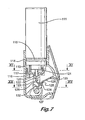
- the dispenser thereshown has a body 101 with a mouthpiece 102 and a pivoted mouthpiece cover 103.
- the latter is pivoted about an axis 104 low in the body and carried on a cam member 105 journalled in the body at openings 106.
- the cover is connected irrotationally to end spigots 107 of the cam member at sides 108 of the cover.
- the spigots and the sides have respective angularly-uniquely formations 109, which determine the angular relationship between the cover and the cam.
- the components are of moulded plastics material, whereby the cam member can be fitted to the body from within by flexure of the latter's walls and the cover can be sprung over the spigots.
- This arrangement closes the body except at (i.) the mouthpiece, (ii.) an upper opening 110 to which a medicament can 111 is fitted and (iii.) air inlets 112, covered by the cover when in its closed position over the mouthpiece.
- the can is held in the opening 110 by detents 114 moulded inside the opening and engaging in a groove 115 formed in the can for retaining its closure collar.
- detents 114 moulded inside the opening and engaging in a groove 115 formed in the can for retaining its closure collar.
- the can and the body 101 are rigidly connected.
- ribs 116 are also moulded inside the body.
- a junction member 117 is slidably accommodated in the body with the ribs engaging in grooves 118 in its periphery,
- the junction member has a socket 120 for an outlet stem 121 of the can.
- the socket is continued by a passage 122, which has a thin wall, kinkable portion 123 and a nozzle end 124. This is in a movable outlet member 125 of a valve part of the junction member.
- the main part of the junction member 117 and the outlet member are connected by a living hinge 126.
- the outlet member has a depending lug 127 for engagement with a cam to be described and a breath actuation flap 128.
- valve portion of the junction member To either side of the valve portion of the junction member, it has two depending fingers 130. These abut - under the force of the internal spring (not shown) of the can - two spaced, main cam lobes 131 on the cam member 105. A secondary cam lobe 132 is arranged between the main lobes.
- the action of the dispenser is as follows:
- the main lobes 131 lift the junction member and stem 121 towards the can.
- the secondary lobe acts on the lug 127 to move the outlet member to a position where the flap 128 is lifted and the kinkable portion 123 is closed.
- the cam timing is such that the flap is lifted prior to full lifting of the junction member.
- the latter has a C-shaped spring 135 and the outlet member has a pip 136, which co-operate in an over-centre manner to hold the flap up as the junction member is fully lifted. This releases a dose into the kinked valve, which retains it.
- the mechanism is reset by closure of the cover over the mouthpiece.
- the junction member drops under the action of the can valve spring and control of the main cam lobes.
- the secondary cam lobe 132 and the flap lug 127 engage on their rear faces, that is the faces opposite from the those which cause lifting of the flap on opening ofthe cover.
- Such engagement is unwanted and the faces are provided with complementary wedge shapes 137,138, whereby the lobe and lug deflect side ways and pass each other. This deflection causes a drag on the lug and keeps the flap in its open position.
- their front faces are provided with complementary V edge and groove formations 139,140.
- the above embodiment has the advantages over conventional dispenser of the same general type - also known as pressurised metered dose inhalers - in which the can is depressible in the body, which extends along the greater part of the length of the can, of:
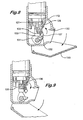
- the dispenser thereshown has a body 201 with a mouthpiece 202 and a pivoted mouthpiece cover 203.
- the mouthpiece is formed as a aperture 2021 in a separate body part 2012 clipped to a main body part 2011.
- the main part 2011 has upper and lower grooves of which the lower 20131only is shown and the mouthpiece part has upper and lower clips of which again only the lower 20132 is shown which engage in the grooves when the mouthpiece part is slid from below to engage with the main part.
- the mouthpiece part is cutaway 2014 with respect to the medicament can 211 fitted to the body, to define an air inlet exposed by the cover when this is open.
- the cover is pivoted about an axis 204 low in the body at the joint between the two body parts.
- Integrally moulded with the cover 203 is a half round shaft 2031, which carries a cam arrangement 205. Whilst both of the body parts have semicircular scallops 2015,2016 to allow the shaft to pass and to provide some location, the primary location for the shaft in its function of reacting cam force is provided in scallops 2017 in flanges 2018 extending up from the end of the body.
- the flanges are integral with the main body part 2011 and extend into the space enclosed by the cover, so as to be able to support the shaft at the joint line between the parts.
- the body parts 2011,2012, and the cover (with the shaft and cam arrangement) 203 are of moulded polypropylene material, whereby they can be fitted together with a modicum of flexure.
- the cam arrangement 205 comprises a pair of cam lobes 2051,2052 and an intermediate shaft 2053.
- the can 211 is held in an opening 210 at the upper end of the main body part 2011 by a pair of location pins 2101 in openings 2102 in sidewalls of the body part.
- the pins positively locate the can with respect to the body by engagement in a groove 215 formed in the can for retaining its closure collar.
- the can and the body 201 are rigidly connected.
- Also moulded inside the body are internal ribs 216.
- a junction member 217 is slidably accommodated in the body with the ribs engaging in grooves 218 in its periphery.
- the junction member also is of moulded polypropylene.
- the junction member has a socket 220 for an outlet stem 221 of the can.
- the socket is continued by a passage 222, which has a thin wall, kinkable portion 223 and a nozzle end 224.
- This is in a movable outlet member 225 of a valve part 2172 of the junction member.
- the main part 2171 of the junction member 217 and the valve part 2172 are connected by a living hinge 226.
- flats 2251 which form the base for a breath actuation flap 228, angled with respect to the flats and connect to living hinge portions at the outside ends of the flats.
- a lug 227 depends from the outlet member for engagement with a cam finger 232 extending from between the pair of cam lobes 2051,2052.
- the socket 220 of the junction member To either side of the socket 220 of the junction member, it has two depending fingers 230 arranged to co-operate with cam lobes at their distal ends 2301. These abut - under the force of the internal spring (not shown) of the can, and with the interposition of two leaves 2019 - the cam lobes 2051,2052.
- the leaves extend in from extensions of the flanges 2018.
- the fingers have shaped portions 2302 on the flap side thereof with detents 2303 for engaging with the flap at the inward ends of the flats 2251.
- the junction member is moulded with the kinkable portion 223 straight and for use, the flap is pivoted to pass over the detents. The latter then form stops for the flap in its open position of the kink tube.
- Additional features are a pair of spring fingers 2252 on the valve part 2172 to either side of the lug 227 and a pair of lugs 236 on the flats 2251 at the hinges. These co-operate with a pair of curved leaf springs 235 on the main part 2171 of the junction member. Further the shaft 2031 has discs 2032 outwards of the cam lobes with finger 2033 for co-operating with the fingers 2252.
- the action ofthe dispenser is as follows:
- the action of closing the cover causes the cam fingers 2033 to engage the flap fingers - should the flap be pivoted towards the can - and pivot the flap to its position in which the nozzle 224 towards the (closed) mouthpiece and the kink tube is unkinked.
- the distal ends 2301 of the fingers 230 of the junction member engage - with the interposition of the leaves 2019 - on a small radius portion of the cam lobes 2051,2052 and the depending lug 227 is positioned in front of engages a small radius portion of the cam finger 232.
- the spring fingers 2252 engage the pair of lugs 236 to urge the flap to its position defined by the detents 2303.
- the cam finger 232 acts on the lug 227 to move the outlet member to a position where the flap 228 is lifted and the kinkable portion 223 is closed.
- the cam timing is such that the flap is lifted before any other action.
- the lugs 236 pass over centre with respect to the spring fingers 2252. The latter urges the flap into abutment with a stop 23 8 formed on the main part 2171 of the junction member 217. In this position, the kink tube is kinked and will not pass a dose about to be released into it.
- the mechanism is reset by closure of the cover over the mouthpiece.
- the junction member drops under the action of the can valve spring and control of the main cam lobes.
- the cam finger 232 and the flap lug 227 engage on their rear faces, that is the faces opposite from the those which cause lifting of the flap on opening of the cover.
- Such engagement is unwanted and the faces are provided with complementary wedge shapes - as shown in Figure 12 - whereby the lobe and lug deflect side ways and pass each other. This deflection causes a drag on the lug and keeps the flap in its open position.
- their front faces are provided with complementary V edge.
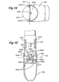
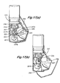
- FIG. 20 the embodiment thereshown has similarities to that of Figures 1 to 5 , but in place of being operated by depression of the can 304, operation is by upwards action on a button 351.
- This dispenser has a body 301 with a mouthpiece 302.
- the aerosol drug can 304 is pinned 3011 in the body.
- the can has a dispensing spout 305, which engages a junction member 306, slidably mounted in the body and incorporating a breath movable flap 307 and a kink valve 308.
- the parts (other than the can) are of injection moulded plastics material.
- the body has a D-shaped cross-section in plan, with the flat 309 of the D at the mouthpiece side 302, the latter being set up from the bottom of the body.
- the junction member 306 is of complementary shape and arranged to closely fit in the body. It has a curved under-contour 310 on the flat side 311 and a slot 312 adjacent the inner end of the flap.
- the movable flap 307 is connected to the main receptor moulding part by a living hinge (not shown) arranged at the centre of curvature of the contour 310, whereby the distal edge 314 of the flap can move with a small clearance from the contour.
- the junction member is moulded with the flap angled down with respect to the use orientation and a linear passage 320 through it.
- the central portion 321 of the passage has a thin wall thickness, whereby when the flap is hinged up, the passage kinks and closes.
- the upper end 322 of the passage is of larger diameter to receive the spout of the can.
- the lower end of the passage forms a spray nozzle 323, which is directed in accordance with the angle of the flap.
- the junction member has two depending leaf springs 334, which abut lugs 336 on the flap for giving it an over-centre action.
- An actuating mechanism 352 is provided beneath the carrier and comprises two abutment fingers 353,354 and the actuation button 351.
- the fingers are interconnected by a yoke 365, which has a pair of apertures 366, through which two additional fingers 367 pass from the button.
- the fingers are positioned on opposite sides of the kink valve, as illustrated in Figure 19 .
- a spring 368 integral with the yoke 365 allows movement of the yoke on the fingers 367, i.e. movement further inwards of the button when the yoke is stopped.
- the length of the fingers is such that on initial movement towards the can of the button, the shorter finger 353 abuts the flap and moves it to kink its tube. This is illustrated in the Figure 18 , by the distance 357 between the end of the long finger 354 and the cap of the can being shorter than the travel 358 allowed between the button and the body.
- the motion of the yoke is stopped by abutment of the long finger 354 on the cap of the can.
- the button can be moved in further with compression of the springs 368 and abutment of the additional fingers 367 on a flat 369 on the junction member, moving it towards the can. This action is against the can's spring and results in dispensing of a dose into the kink tube.
- Inhalation draws the flap down, releasing the dose, with the flap being stopped in the desired position by the shorter finger 353. Release of the button allows return of the components to their original position.
Landscapes
- Health & Medical Sciences (AREA)
- Engineering & Computer Science (AREA)
- Bioinformatics & Cheminformatics (AREA)
- Pulmonology (AREA)
- Anesthesiology (AREA)
- Biomedical Technology (AREA)
- Heart & Thoracic Surgery (AREA)
- Hematology (AREA)
- Life Sciences & Earth Sciences (AREA)
- Animal Behavior & Ethology (AREA)
- General Health & Medical Sciences (AREA)
- Public Health (AREA)
- Veterinary Medicine (AREA)
- Containers And Packaging Bodies Having A Special Means To Remove Contents (AREA)
Claims (27)
- Spender für eine gasförmige, gasübertragene oder Tröpfchensubstanz, die in dessen Quelle enthalten ist, wobei der Spender umfasst:- ein Gehäuse (1, 101) mit einem Mundstück (2, 102);- ein Verbindungselement (6, 117) im Gehäuse (1, 101) für die Substanzquelle (4); und- ein atembetätigbares Ventil für das Steuern der Freigabe des Gases oder der Flüssigkeit, das/die Substanz enthält oder aufweist, wobei das Ventil aufweist:- einen flexiblen Schlauch (8, 122) für das Aufnehmen des Gases oder der Flüssigkeit, wobei sich der Schlauch von einem Ventileintritt aus erstreckt, der mit dem Verbindungselement (6, 117) verbunden ist und einen Abschnitt aufweist, der für ein Verschließen des Ventils knickbar und in eine offene Position beweglich ist, in der der Schlauch für das Öffnen des Ventils begradigt ist; und- ein Element (125), das für eine Bewegung im Gehäuse durch Inhalation angeordnet ist, um das Ventil zu begradigen;
wobei der Schlauch (8, 122) bis zu einem Verschließen geknickt wird, wenn sich das bewegliche Element (125) in einer Bereitschaftsposition befindet, und begradigt wird, wenn das bewegliche Element (125) bei der Inhalation für eine Freigabe des Gases oder der Flüssigkeit bewegt wird;
wobei der Spender ebenfalls umfasst:- eine Feder (35, 36, 135, 136) für das Unterstützen der Bewegung, um den Schlauch zu begradigen; und- ein Mittel (35, 36, 135, 136), um das bewegliche Element (125) in der Bereitschaftsposition zu halten, um den Schlauch (8, 122) durch Knicken vor der Inhalation zu verschließen. - Spender nach Anspruch 1, bei dem das Haltemittel ein reibschlüssiges Mittel ist, das das bewegliche Element für eine Freigabe betriebsbereit hält und durch Überwinden der Reibungskraft freigegeben wird, die das bewegliche Element in seiner Betriebsbereitschaftsposition hält, oder eine Halterung des beweglichen Elementes über der Mitte mit Bezugnahme auf die Feder ist, wobei die Feder (35, 36, 135, 136) wirkt, um das bewegliche Element in die Betriebsbereitschaftsposition, wenn es nahe dieser Position ist, und weg von ihr zu treiben, wenn die Inhalationskraft am beweglichen Element bewirkt, dass die Feder über die Mitte nach einer geringen Bewegung des beweglichen Elementes gelangt, um das Begradigen zu unterstützen.
- Spender nach Anspruch 2, der einen Spannmechanismus umfasst, um das bewegliche Element (125) in seine eingespannte Position zu bewegen, in der der Schlauch geknickt wird.
- Spender nach Anspruch 3, wobei der Spender eine Substanzquelle (4) aufweist, wobei der Spannmechanismus so ausgebildet ist, dass er durch einen manuell beweglichen Hebel oder Knopf betätigt wird, und wobei der Spender ein Mittel für das Anordnen der Quelle (4) im Gehäuse umfasst, wobei das Verbindungselement in Richtung dieses verschiebbar ist.
- Spender nach Anspruch 4, bei dem der Spannmechanismus so ausgebildet ist, dass er durch Niederdrücken der Quelle (4) in Richtung des Gehäuses betätigt wird.
- Spender nach Anspruch 1 bis 5, bei dem das bewegliche Element (125) translatorisch oder drehbar im Gehäuse montiert ist.
- Spender nach Anspruch 6, bei dem das bewegliche Element (125) drehbar im Gehäuse um einen Drehpunkt montiert ist, der im Gehäuse fixiert ist.
- Spender nach Anspruch 7, bei dem der Drehpunkt auf einem Träger vorhanden ist, der selbst translatorisch im Gehäuse montiert ist.
- Spender nach einem der Ansprüche 6 bis 8, bei dem das bewegliche Element (125) drehbar montiert und ein Anschlag (133) vorhanden ist, um es in einer Position anzuhalten, in der ein Auslass (124) aus dem Schlauch direkt aus dem Mundstück heraus gerichtet ist.
- Spender nach einem der Ansprüche 1 bis 9, bei dem:- das bewegliche Element (125) eine Klappe (7, 128) ist oder umfasst, die im Gehäuse (1, 101) für die Wirkung des Atems auf sie bei der Inhalation angeordnet ist;- das Verbindungselement (6, 117), der flexible Schlauch (8, 122) und die bewegliche Klappe (7, 128) ein einzelnes Spritzgießteil aus Kunststoffmaterial sind; und- die bewegliche Klappe (7, 128) mit dem Verbindungselement (6, 117) mittels eines aktiven Gelenkes (13, 126) verbunden ist.
- Spender nach Anspruch 2 oder einem der Ansprüche 3 bis 10 als Anhang zum Anspruch 2, bei dem das Haltemittel ein übermittiger Mechanismus ist, der einen Ansatz (136) und eine Feder (135) aufweist, beide zusammenhängend mit dem einzelnen Spritzgießteil geformt, eines mit dem Verbindungselement und das andere mit der Klappe.
- Spender nach Anspruch 11, bei dem der Ansatz (136) zusammenhängend mit der Klappe (128) für eine Drehbewegung damit um das aktive Gelenk geformt ist, und wobei die Feder (135) zusammenhängend mit dem Verbindungselement (117) geformt ist.
- Spender nach Anspruch 12, bei dem die Feder eine Blattfeder ist, die normalerweise die Klappe in eine offene Position des Ventils treibt und die Klappe in ihre Betriebsbereitschaftsposition treibt, wenn sie übermittig in diese Position gelangt.
- Spender nach Anspruch 4 oder einem der Ansprüche 5 bis 13 als Anhang zum Anspruch 4, bei dem:- sowohl die Quelle (4) als auch das Verbindungselement (6) translatorisch im Gehäuse (1) für eine Bewegung durch Niederdrücken der Quelle (4) in Richtung des Gehäuses (1) montiert sind; und- das elastische Mittel des Verbindungselementes gegen das Gehäuse (1) wirkt, die Bewegung des Verbindungselementes (6) aufnimmt, was zum Drehen der Klappe (7) führt, die Bewegung des Verbindungselementes (6) bei einer weiteren Bewegung der Quelle (4) mit Bezugnahme auf das Verbindungselement (6) für das Ausgeben einer Dosis begrenzt und das Verbindungselement (6) (und die Quelle (4)) bei Freigabe des Druckes auf die Quelle (4) zurückführt; und
wobei das Mittel zum Drehen der Klappe aufweist:- ein Betätigungselement (41), das aufweist:- einen ersten Anschlag (44), der mit Bezugnahme auf das Gehäuse (1) beweglich montiert ist, und gegen den die Klappe (7) für eine Drehbewegung dieses bei der anfänglichen Bewegung des Verbindungselementes (6) (und der Quelle (4)) gepresst wird, was die Klappe (7) gegen den ersten Anschlag (44) bewegt;- einen zweiten Anschlag (43) für das Trennen des ersten Anschlages (44) von der Klappe (7), wobei der zweite Anschlag:- mit dem ersten Anschlag (44) verbunden ist,- beweglich mit Bezugnahme auf das Gehäuse (1) montiert ist, und- angeordnet ist, um an die Quelle (4) anzustoßen und sie bei seiner weiteren Bewegung fortzubewegen;- ein elastisches Mittel des Anschlages, das gegen das Gehäuse (1) wirkt, die weitere Bewegung der Quelle (4) und des zweiten Anschlages (43) aufnimmt, der dagegen anstößt, die weitere Bewegung beim Ausgeben der Dosis begrenzt und die Anschläge bei der Freigabe des Druckes auf die Quelle (4) zurückführt. - Spender nach Anspruch 14, bei dem das Betätigungselement ein weiteres einzelnes Spritzgießteil ist.
- Spender nach Anspruch 14 oder 15, bei dem der erste Anschlag (44) so positioniert wird, dass die Bewegung der Klappe (7) beim Freigeben der Dosis begrenzt wird, damit der Auslass des flexiblen Schlauches (8) aus dem Mundstück (2) heraus gerichtet ist.
- Spender nach Anspruch 3 oder einem der Ansprüche 4 bis 16 als Anhang zum Anspruch 3, wobei der Spender eine Substanzquelle (4) aufweist und der Spannmechanismus einen Spannhebel (103) umfasst.
- Spender nach Anspruch 17, bei dem der Spannhebel ein Deckel (103) für das Mundstück vor dem Ausgeben einer Dosis aus der Quelle ist, wobei eine Dosis beim Öffnen des Deckels zum Knickventil ausgegeben wird.
- Spender nach Anspruch 17 oder Anspruch 18, bei dem der Spannhebel (103) einen Hauptnocken (105) enthält, der den Spannmechanismus im Zusammenwirken mit dem Verbindungselement (117) und/oder, wenn vom Anspruch 8 abhängig, dem Träger aufweist, und/oder, wobei das Mittel für das Drehen der Klappe ein sekundärer Kurvenmechanismus ist, der zwischen dem Spannhebel und der Klappe wirkt.
- Spender nach Anspruch 19, bei dem der sekundäre Kurvenmechanismus einen Finger auf dem Nocken des Spannhebels und einen Finger auf der Klappe aufweist, wobei die Finger in Eingriff kommen, während der Spannhebel geöffnet wird, um die Klappe in ihre Bereitschaftsposition zu bewegen.
- Spender nach Anspruch 20, bei dem die Finger so geformt sind, dass sie sich bei der Rückwärtsbewegung des Spannhebels voneinander weg biegen, wobei sich die Klappe in ihrer Position befindet, die dem Ventil entspricht, wenn es offen ist.
- Spender nach einem der Ansprüche 19 bis 21, der einen tertiären Kurvenmechanismus für das Rückführen der Klappe in ihre offene Ventilposition bei der Rückwärtsbewegung des Spannhebels umfasst.
- Spender nach Anspruch 22, bei dem der tertiäre Kurvenmechanismus einen Finger am Spannhebel und einen Finger auf der Klappe aufweist, wobei die Finger in Eingriff kommen, während der Deckel geschlossen wird, um die Klappe in ihre offene Ventilposition zu bewegen, wenn sie nicht bereits in dieser Position ist.
- Spender nach einem der Ansprüche 19 bis 23, bei dem das Gehäuse einen oder mehrere Stege umfasst, die sich zwischen dem Hauptnocken und dem beweglichen Verbindungselement für das Reagieren auf eine seitliche Nockenkraft und das Übertragen der Nockenlängskraft auf das bewegliche Verbindungselement und/oder den Träger, wenn vom Anspruch 8 abhängig, erstrecken.
- Spender nach einem der Ansprüche 19 bis 24, bei dem der Spannhebel eine Welle mit dem darauf ausgebildeten Hauptnocken aufweist, wobei die Welle eine hohle, halbrunde Konfiguration aufweist und das Gehäuse mindestens einen teilweise offenen Lagerzapfen für die halbrunde Welle umfasst.
- Spender nach einem der Ansprüche 1 bis 25, bei dem das Gehäuse ein sekundäres Gehäuseteil umfasst, das am Hauptgehäuseteil befestigt werden kann, um das Mundstück und einen Lufteintritt zwischen den zwei Teilen bereitzustellen.
- Spender nach einem der vorhergehenden Ansprüche, bei dem der Spender eine Substanzquelle (4) aufweist und die Substanzquelle ein Dosierventil umfasst, wobei es eine abgemessene Dosis jedes Mal dann abgibt, wenn der Spender betätigt wird, oder wobei die Quelle (4) ein Ventil für eine nicht dosierte Menge umfasst, wobei die Dosis durch die Kapazität des atembetätigbaren Ventils abgemessen wird.
Priority Applications (1)
| Application Number | Priority Date | Filing Date | Title |
|---|---|---|---|
| CY20151100767T CY1116670T1 (el) | 2000-07-24 | 2015-09-01 | Διανεμητης |
Applications Claiming Priority (3)
| Application Number | Priority Date | Filing Date | Title |
|---|---|---|---|
| GB0018051A GB0018051D0 (en) | 2000-07-24 | 2000-07-24 | Dispenser |
| GB0023024A GB0023024D0 (en) | 2000-09-20 | 2000-09-20 | Dispenser |
| EP01984480A EP1303326B1 (de) | 2000-07-24 | 2001-07-24 | Spender |
Related Parent Applications (2)
| Application Number | Title | Priority Date | Filing Date |
|---|---|---|---|
| EP01984480A Division EP1303326B1 (de) | 2000-07-24 | 2001-07-24 | Spender |
| EP01984480.2 Division | 2001-07-24 |
Publications (2)
| Publication Number | Publication Date |
|---|---|
| EP2292287A1 EP2292287A1 (de) | 2011-03-09 |
| EP2292287B1 true EP2292287B1 (de) | 2015-06-10 |
Family
ID=26244708
Family Applications (4)
| Application Number | Title | Priority Date | Filing Date |
|---|---|---|---|
| EP01984480A Expired - Lifetime EP1303326B1 (de) | 2000-07-24 | 2001-07-24 | Spender |
| EP10181625.4A Expired - Lifetime EP2263729B1 (de) | 2000-07-24 | 2001-07-24 | Spender |
| EP10181637.9A Expired - Lifetime EP2292287B1 (de) | 2000-07-24 | 2001-07-24 | Spender |
| EP10181653.6A Expired - Lifetime EP2292288B1 (de) | 2000-07-24 | 2001-07-24 | Spender |
Family Applications Before (2)
| Application Number | Title | Priority Date | Filing Date |
|---|---|---|---|
| EP01984480A Expired - Lifetime EP1303326B1 (de) | 2000-07-24 | 2001-07-24 | Spender |
| EP10181625.4A Expired - Lifetime EP2263729B1 (de) | 2000-07-24 | 2001-07-24 | Spender |
Family Applications After (1)
| Application Number | Title | Priority Date | Filing Date |
|---|---|---|---|
| EP10181653.6A Expired - Lifetime EP2292288B1 (de) | 2000-07-24 | 2001-07-24 | Spender |
Country Status (11)
| Country | Link |
|---|---|
| US (1) | US7036505B2 (de) |
| EP (4) | EP1303326B1 (de) |
| AU (2) | AU2002229143B2 (de) |
| CA (3) | CA2764292C (de) |
| CY (4) | CY1113139T1 (de) |
| DK (4) | DK2263729T3 (de) |
| ES (4) | ES2656407T3 (de) |
| GB (1) | GB2381461C (de) |
| NZ (3) | NZ535187A (de) |
| PT (4) | PT2292287E (de) |
| WO (1) | WO2002011802A2 (de) |
Families Citing this family (40)
| Publication number | Priority date | Publication date | Assignee | Title |
|---|---|---|---|---|
| US5823179A (en) * | 1996-02-13 | 1998-10-20 | 1263152 Ontario Inc. | Nebulizer apparatus and method |
| GB0029612D0 (en) * | 2000-12-05 | 2001-01-17 | Bacon Raymond J | Drug dispenser |
| AU2002238801A1 (en) * | 2001-03-20 | 2002-10-03 | Trudell Medical International | Nebulizer apparatus and method |
| US7435241B1 (en) * | 2001-11-17 | 2008-10-14 | Dascanio Gustavo A | Fluid dispenser closure including tube having hydrophilic and hydrophobic portions |
| US7814900B2 (en) * | 2002-03-22 | 2010-10-19 | Clinical Designs Limited | Can fixture |
| US6904908B2 (en) | 2002-05-21 | 2005-06-14 | Trudell Medical International | Visual indicator for an aerosol medication delivery apparatus and system |
| US6910579B2 (en) | 2002-05-28 | 2005-06-28 | Georgia-Pacific Corporation | Refillable flexible sheet dispenser |
| GB2398254B (en) * | 2003-02-11 | 2005-12-07 | Bespak Plc | Dispensing Apparatus |
| GB0304000D0 (en) * | 2003-02-21 | 2003-03-26 | Clinical Designs Ltd | Dispenser |
| JP4943838B2 (ja) | 2003-04-09 | 2012-05-30 | ネクター セラピューティクス | 空気入口シールドを備えたエアゾール化装置 |
| US8869794B1 (en) | 2003-04-09 | 2014-10-28 | Novartis Pharma Ag | Aerosolization apparatus with capsule puncturing member |
| AU158576S (en) * | 2003-07-05 | 2006-08-22 | Clinical Designs Ltd | Inhaler |
| GB0327112D0 (en) * | 2003-11-21 | 2003-12-24 | Clincial Designs Ltd | Dispenser and reservoir |
| GB0328859D0 (en) * | 2003-12-12 | 2004-01-14 | Clinical Designs Ltd | Dispenser and counter |
| GB0425518D0 (en) | 2004-11-19 | 2004-12-22 | Clinical Designs Ltd | Substance source |
| WO2006062449A1 (en) * | 2004-12-10 | 2006-06-15 | Ernst Hörlins Ingenjörsbyra AB | Breath actuated dose inhaler |
| GB0428204D0 (en) | 2004-12-23 | 2005-01-26 | Clinical Designs Ltd | Medicament container |
| GB0505543D0 (en) * | 2005-03-17 | 2005-04-27 | Glaxo Group Ltd | Inhalation devices |
| GB0518400D0 (en) | 2005-09-09 | 2005-10-19 | Clinical Designs Ltd | Dispenser |
| US20070095342A1 (en) * | 2005-10-18 | 2007-05-03 | Bijan Olfati | Accessorized inhaler |
| WO2008058539A1 (en) * | 2006-11-14 | 2008-05-22 | Bang & Olufsen Medicom A/S | An inhaler with a forward metering valve |
| USD582544S1 (en) | 2007-08-09 | 2008-12-09 | Nycomed Gmbh | Metered dose inhaler |
| EP2082759A1 (de) * | 2008-01-24 | 2009-07-29 | Boehringer Ingelheim International GmbH | Inhalator |
| ES2423587T3 (es) | 2008-07-10 | 2013-09-23 | Bang & Olufsen Medicom A/S | Inhalador y procedimiento de operación del mismo |
| GB0904059D0 (en) | 2009-03-10 | 2009-04-22 | Euro Celtique Sa | Counter |
| GB0904040D0 (en) | 2009-03-10 | 2009-04-22 | Euro Celtique Sa | Counter |
| GB0913488D0 (en) * | 2009-08-01 | 2009-09-16 | Reckitt Benckiser Nv | Product |
| GB201001760D0 (en) * | 2010-02-03 | 2010-03-24 | Bacon Raymond J | Dipenser |
| GB201101006D0 (en) * | 2011-01-21 | 2011-03-09 | Reckitt Benckiser Nv | Product |
| EP2736476A4 (de) * | 2011-07-27 | 2015-03-18 | Nigel Kelly | Tankmodul für einen pumpenspender |
| GB201118845D0 (en) | 2011-11-01 | 2011-12-14 | Euro Celtique Sa | Dispenser |
| GB201118842D0 (en) | 2011-11-01 | 2011-12-14 | Euro Celtique Sa | Dispenser cap arrangement |
| AU2014253997B2 (en) * | 2013-04-16 | 2019-01-03 | Aerami Therapeutics, Inc. | Liquid dispensing and methods for dispensing liquids |
| ES2966349T3 (es) | 2016-05-19 | 2024-04-22 | Trudell Medical Int | Cámara de retención con válvula inteligente |
| ES2988939T3 (es) | 2016-07-08 | 2024-11-22 | Trudell Medical Int Inc | Dispositivo de presión espiratoria positiva oscilante inteligente |
| US10786638B2 (en) | 2016-07-08 | 2020-09-29 | Trudell Medical International | Nebulizer apparatus and method |
| CN110049795B (zh) | 2016-12-09 | 2022-07-19 | 特鲁德尔医学国际公司 | 智能雾化器 |
| US11666801B2 (en) | 2018-01-04 | 2023-06-06 | Trudell Medical International | Smart oscillating positive expiratory pressure device |
| WO2021038467A1 (en) | 2019-08-27 | 2021-03-04 | Trudell Medical International | Smart oscillating positive expiratory pressure device |
| CN115105695B (zh) * | 2022-06-02 | 2023-05-16 | 宁波职业技术学院 | 一种哮喘呼吸器及哮喘呼吸器的使用方法 |
Family Cites Families (15)
| Publication number | Priority date | Publication date | Assignee | Title |
|---|---|---|---|---|
| CH365596A (de) * | 1957-09-14 | 1962-11-15 | Gauthier Gmbh A | Werkzeugmaschine mit um eine volle Umdrehung schaltbarem Werkstückträger |
| US3181743A (en) * | 1961-06-19 | 1965-05-04 | Sidney M Libit | Dispensing closures of the collapsible wall type |
| NL299788A (de) * | 1962-11-05 | |||
| US4576157A (en) * | 1983-10-24 | 1986-03-18 | Raghuprasad Puthalath K | Oral inhalation apparatus |
| GB8328808D0 (en) * | 1983-10-28 | 1983-11-30 | Riker Laboratories Inc | Inhalation responsive dispensers |
| CA2058764A1 (en) * | 1989-04-28 | 1990-10-29 | Peter D. Hodson | Dry powder inhalation device |
| GB8909891D0 (en) * | 1989-04-28 | 1989-06-14 | Riker Laboratories Inc | Device |
| GB8919131D0 (en) * | 1989-08-23 | 1989-10-04 | Riker Laboratories Inc | Inhaler |
| FR2658081B1 (fr) * | 1990-02-09 | 1995-06-30 | Pesenti Yvan | Dispositif d'automatisation et synchronisation des appareils aerosols a pompe doseuse. |
| US5113855A (en) * | 1990-02-14 | 1992-05-19 | Newhouse Michael T | Powder inhaler |
| GB9026191D0 (en) * | 1990-12-01 | 1991-01-16 | Harris Pharma Ltd | Breath actuated dispensing device |
| US5469843A (en) * | 1991-11-12 | 1995-11-28 | Minnesota Mining And Manufacturing Company | Inhalation device |
| GB9705657D0 (en) * | 1997-03-19 | 1997-05-07 | Bacon Raymond J | Dispenser |
| ES2229495T3 (es) * | 1997-05-23 | 2005-04-16 | Pa Knowledge Limited | Dispositivo inhalador. |
| GB0101944D0 (en) * | 2001-01-25 | 2001-03-07 | Bacon Raymond J | Dispenser |
-
2001
- 2001-07-24 ES ES10181653.6T patent/ES2656407T3/es not_active Expired - Lifetime
- 2001-07-24 AU AU2002229143A patent/AU2002229143B2/en not_active Ceased
- 2001-07-24 ES ES10181625.4T patent/ES2554256T3/es not_active Expired - Lifetime
- 2001-07-24 PT PT101816379T patent/PT2292287E/pt unknown
- 2001-07-24 DK DK10181625.4T patent/DK2263729T3/en active
- 2001-07-24 DK DK01984480.2T patent/DK1303326T3/da active
- 2001-07-24 WO PCT/GB2001/003313 patent/WO2002011802A2/en not_active Ceased
- 2001-07-24 US US10/333,891 patent/US7036505B2/en not_active Expired - Lifetime
- 2001-07-24 NZ NZ535187A patent/NZ535187A/en not_active IP Right Cessation
- 2001-07-24 PT PT01984480T patent/PT1303326E/pt unknown
- 2001-07-24 DK DK10181653.6T patent/DK2292288T3/en active
- 2001-07-24 ES ES01984480T patent/ES2390658T3/es not_active Expired - Lifetime
- 2001-07-24 ES ES10181637.9T patent/ES2544951T3/es not_active Expired - Lifetime
- 2001-07-24 PT PT101816536T patent/PT2292288T/pt unknown
- 2001-07-24 EP EP01984480A patent/EP1303326B1/de not_active Expired - Lifetime
- 2001-07-24 DK DK10181637.9T patent/DK2292287T3/en active
- 2001-07-24 NZ NZ524081A patent/NZ524081A/en not_active IP Right Cessation
- 2001-07-24 AU AU2914302A patent/AU2914302A/xx active Pending
- 2001-07-24 CA CA2764292A patent/CA2764292C/en not_active Expired - Lifetime
- 2001-07-24 EP EP10181625.4A patent/EP2263729B1/de not_active Expired - Lifetime
- 2001-07-24 CA CA002417575A patent/CA2417575C/en not_active Expired - Lifetime
- 2001-07-24 PT PT101816254T patent/PT2263729E/pt unknown
- 2001-07-24 EP EP10181637.9A patent/EP2292287B1/de not_active Expired - Lifetime
- 2001-07-24 EP EP10181653.6A patent/EP2292288B1/de not_active Expired - Lifetime
- 2001-07-24 GB GB0301444.6A patent/GB2381461C/en not_active Expired - Fee Related
- 2001-07-24 CA CA2640679A patent/CA2640679C/en not_active Expired - Lifetime
-
2004
- 2004-09-08 NZ NZ535188A patent/NZ535188A/en not_active IP Right Cessation
-
2012
- 2012-09-17 CY CY20121100843T patent/CY1113139T1/el unknown
-
2015
- 2015-09-01 CY CY20151100767T patent/CY1116670T1/el unknown
- 2015-12-22 CY CY20151101169T patent/CY1117068T1/el unknown
-
2018
- 2018-01-10 CY CY20181100030T patent/CY1119759T1/el unknown
Also Published As
Similar Documents
| Publication | Publication Date | Title |
|---|---|---|
| EP2292287B1 (de) | Spender | |
| AU2002229143A1 (en) | Dispenser | |
| AU2004212768B2 (en) | Dispenser | |
| AU2002226547B2 (en) | Dispenser | |
| AU2002226547A1 (en) | Dispenser | |
| GB2381462A (en) | Dispenser | |
| HK1151751B (en) | Dispenser | |
| HK1151749A (en) | Dispenser | |
| HK1151749B (en) | Dispenser | |
| HK1151750B (en) | Dispenser | |
| ZA200300660B (en) | Dispenser. | |
| HK1076758B (en) | Dispenser |
Legal Events
| Date | Code | Title | Description |
|---|---|---|---|
| PUAI | Public reference made under article 153(3) epc to a published international application that has entered the european phase |
Free format text: ORIGINAL CODE: 0009012 |
|
| AC | Divisional application: reference to earlier application |
Ref document number: 1303326 Country of ref document: EP Kind code of ref document: P |
|
| AK | Designated contracting states |
Kind code of ref document: A1 Designated state(s): AT BE CH CY DE DK ES FI FR GB GR IE IT LI LU MC NL PT SE TR |
|
| 17P | Request for examination filed |
Effective date: 20110908 |
|
| REG | Reference to a national code |
Ref country code: HK Ref legal event code: DE Ref document number: 1151751 Country of ref document: HK |
|
| GRAP | Despatch of communication of intention to grant a patent |
Free format text: ORIGINAL CODE: EPIDOSNIGR1 |
|
| INTG | Intention to grant announced |
Effective date: 20141222 |
|
| RIN1 | Information on inventor provided before grant (corrected) |
Inventor name: BACON, RAYMOND JOHN Inventor name: MCDERMENT, IAIN GRIERSON |
|
| GRAS | Grant fee paid |
Free format text: ORIGINAL CODE: EPIDOSNIGR3 |
|
| GRAA | (expected) grant |
Free format text: ORIGINAL CODE: 0009210 |
|
| AC | Divisional application: reference to earlier application |
Ref document number: 1303326 Country of ref document: EP Kind code of ref document: P |
|
| AK | Designated contracting states |
Kind code of ref document: B1 Designated state(s): AT BE CH CY DE DK ES FI FR GB GR IE IT LI LU MC NL PT SE TR |
|
| REG | Reference to a national code |
Ref country code: GB Ref legal event code: FG4D |
|
| REG | Reference to a national code |
Ref country code: CH Ref legal event code: EP |
|
| REG | Reference to a national code |
Ref country code: AT Ref legal event code: REF Ref document number: 730635 Country of ref document: AT Kind code of ref document: T Effective date: 20150715 |
|
| REG | Reference to a national code |
Ref country code: DE Ref legal event code: R096 Ref document number: 60149404 Country of ref document: DE |
|
| REG | Reference to a national code |
Ref country code: IE Ref legal event code: FG4D |
|
| REG | Reference to a national code |
Ref country code: CH Ref legal event code: NV Representative=s name: MARKS AND CLERK (LUXEMBOURG) LLP, CH |
|
| REG | Reference to a national code |
Ref country code: ES Ref legal event code: FG2A Ref document number: 2544951 Country of ref document: ES Kind code of ref document: T3 Effective date: 20150907 |
|
| REG | Reference to a national code |
Ref country code: DK Ref legal event code: T3 Effective date: 20150910 |
|
| REG | Reference to a national code |
Ref country code: PT Ref legal event code: SC4A Free format text: AVAILABILITY OF NATIONAL TRANSLATION Effective date: 20150810 |
|
| REG | Reference to a national code |
Ref country code: SE Ref legal event code: TRGR |
|
| REG | Reference to a national code |
Ref country code: NL Ref legal event code: FP |
|
| REG | Reference to a national code |
Ref country code: HK Ref legal event code: GR Ref document number: 1151751 Country of ref document: HK |
|
| REG | Reference to a national code |
Ref country code: GR Ref legal event code: EP Ref document number: 20150401773 Country of ref document: GR Effective date: 20150929 |
|
| REG | Reference to a national code |
Ref country code: DE Ref legal event code: R097 Ref document number: 60149404 Country of ref document: DE |
|
| PLBE | No opposition filed within time limit |
Free format text: ORIGINAL CODE: 0009261 |
|
| STAA | Information on the status of an ep patent application or granted ep patent |
Free format text: STATUS: NO OPPOSITION FILED WITHIN TIME LIMIT |
|
| 26N | No opposition filed |
Effective date: 20160311 |
|
| REG | Reference to a national code |
Ref country code: FR Ref legal event code: PLFP Year of fee payment: 16 |
|
| REG | Reference to a national code |
Ref country code: AT Ref legal event code: UEP Ref document number: 730635 Country of ref document: AT Kind code of ref document: T Effective date: 20150610 |
|
| REG | Reference to a national code |
Ref country code: FR Ref legal event code: PLFP Year of fee payment: 17 |
|
| REG | Reference to a national code |
Ref country code: FR Ref legal event code: PLFP Year of fee payment: 18 |
|
| PGFP | Annual fee paid to national office [announced via postgrant information from national office to epo] |
Ref country code: PT Payment date: 20190621 Year of fee payment: 19 |
|
| PGFP | Annual fee paid to national office [announced via postgrant information from national office to epo] |
Ref country code: LU Payment date: 20190722 Year of fee payment: 19 Ref country code: NL Payment date: 20190719 Year of fee payment: 19 |
|
| PGFP | Annual fee paid to national office [announced via postgrant information from national office to epo] |
Ref country code: DK Payment date: 20190723 Year of fee payment: 19 Ref country code: IE Payment date: 20190723 Year of fee payment: 19 Ref country code: MC Payment date: 20190712 Year of fee payment: 19 Ref country code: FI Payment date: 20190722 Year of fee payment: 19 Ref country code: TR Payment date: 20190718 Year of fee payment: 19 Ref country code: DE Payment date: 20190719 Year of fee payment: 19 Ref country code: CY Payment date: 20190718 Year of fee payment: 19 Ref country code: IT Payment date: 20190729 Year of fee payment: 19 Ref country code: ES Payment date: 20190822 Year of fee payment: 19 Ref country code: FR Payment date: 20190719 Year of fee payment: 19 Ref country code: SE Payment date: 20190719 Year of fee payment: 19 |
|
| PGFP | Annual fee paid to national office [announced via postgrant information from national office to epo] |
Ref country code: GR Payment date: 20190719 Year of fee payment: 19 Ref country code: BE Payment date: 20190718 Year of fee payment: 19 |
|
| PGFP | Annual fee paid to national office [announced via postgrant information from national office to epo] |
Ref country code: GB Payment date: 20190719 Year of fee payment: 19 Ref country code: AT Payment date: 20190722 Year of fee payment: 19 |
|
| PGFP | Annual fee paid to national office [announced via postgrant information from national office to epo] |
Ref country code: CH Payment date: 20190719 Year of fee payment: 19 |
|
| REG | Reference to a national code |
Ref country code: DE Ref legal event code: R119 Ref document number: 60149404 Country of ref document: DE |
|
| REG | Reference to a national code |
Ref country code: FI Ref legal event code: MAE |
|
| PG25 | Lapsed in a contracting state [announced via postgrant information from national office to epo] |
Ref country code: MC Free format text: LAPSE BECAUSE OF NON-PAYMENT OF DUE FEES Effective date: 20200731 |
|
| REG | Reference to a national code |
Ref country code: CH Ref legal event code: PL |
|
| REG | Reference to a national code |
Ref country code: DK Ref legal event code: EBP Effective date: 20200731 |
|
| REG | Reference to a national code |
Ref country code: SE Ref legal event code: EUG |
|
| REG | Reference to a national code |
Ref country code: NL Ref legal event code: MM Effective date: 20200801 |
|
| REG | Reference to a national code |
Ref country code: AT Ref legal event code: MM01 Ref document number: 730635 Country of ref document: AT Kind code of ref document: T Effective date: 20200724 |
|
| GBPC | Gb: european patent ceased through non-payment of renewal fee |
Effective date: 20200724 |
|
| REG | Reference to a national code |
Ref country code: BE Ref legal event code: MM Effective date: 20200731 |
|
| PG25 | Lapsed in a contracting state [announced via postgrant information from national office to epo] |
Ref country code: CH Free format text: LAPSE BECAUSE OF NON-PAYMENT OF DUE FEES Effective date: 20200731 Ref country code: CY Free format text: LAPSE BECAUSE OF NON-PAYMENT OF DUE FEES Effective date: 20200724 Ref country code: GR Free format text: LAPSE BECAUSE OF NON-PAYMENT OF DUE FEES Effective date: 20210210 Ref country code: LI Free format text: LAPSE BECAUSE OF NON-PAYMENT OF DUE FEES Effective date: 20200731 Ref country code: FR Free format text: LAPSE BECAUSE OF NON-PAYMENT OF DUE FEES Effective date: 20200731 Ref country code: FI Free format text: LAPSE BECAUSE OF NON-PAYMENT OF DUE FEES Effective date: 20200724 Ref country code: GB Free format text: LAPSE BECAUSE OF NON-PAYMENT OF DUE FEES Effective date: 20200724 Ref country code: NL Free format text: LAPSE BECAUSE OF NON-PAYMENT OF DUE FEES Effective date: 20200801 Ref country code: LU Free format text: LAPSE BECAUSE OF NON-PAYMENT OF DUE FEES Effective date: 20200724 Ref country code: PT Free format text: LAPSE BECAUSE OF NON-PAYMENT OF DUE FEES Effective date: 20210226 |
|
| PG25 | Lapsed in a contracting state [announced via postgrant information from national office to epo] |
Ref country code: SE Free format text: LAPSE BECAUSE OF NON-PAYMENT OF DUE FEES Effective date: 20200725 Ref country code: DE Free format text: LAPSE BECAUSE OF NON-PAYMENT OF DUE FEES Effective date: 20210202 Ref country code: AT Free format text: LAPSE BECAUSE OF NON-PAYMENT OF DUE FEES Effective date: 20200724 Ref country code: BE Free format text: LAPSE BECAUSE OF NON-PAYMENT OF DUE FEES Effective date: 20200731 |
|
| PG25 | Lapsed in a contracting state [announced via postgrant information from national office to epo] |
Ref country code: DK Free format text: LAPSE BECAUSE OF NON-PAYMENT OF DUE FEES Effective date: 20200731 Ref country code: IE Free format text: LAPSE BECAUSE OF NON-PAYMENT OF DUE FEES Effective date: 20200724 |
|
| PG25 | Lapsed in a contracting state [announced via postgrant information from national office to epo] |
Ref country code: IT Free format text: LAPSE BECAUSE OF NON-PAYMENT OF DUE FEES Effective date: 20200724 |
|
| PG25 | Lapsed in a contracting state [announced via postgrant information from national office to epo] |
Ref country code: PT Free format text: LAPSE BECAUSE OF EXPIRATION OF PROTECTION Effective date: 20210803 |
|
| REG | Reference to a national code |
Ref country code: ES Ref legal event code: FD2A Effective date: 20211203 |
|
| PG25 | Lapsed in a contracting state [announced via postgrant information from national office to epo] |
Ref country code: ES Free format text: LAPSE BECAUSE OF NON-PAYMENT OF DUE FEES Effective date: 20200725 |
|
| PG25 | Lapsed in a contracting state [announced via postgrant information from national office to epo] |
Ref country code: TR Free format text: LAPSE BECAUSE OF NON-PAYMENT OF DUE FEES Effective date: 20200724 |
|
| PG25 | Lapsed in a contracting state [announced via postgrant information from national office to epo] |
Ref country code: PT Free format text: LAPSE BECAUSE OF NON-PAYMENT OF DUE FEES Effective date: 20200826 |
|
| PG25 | Lapsed in a contracting state [announced via postgrant information from national office to epo] |
Ref country code: PT Free format text: LAPSE BECAUSE OF NON-PAYMENT OF DUE FEES Effective date: 20200826 |