EP2292314B1 - Düse zum Verteilen von pulverförmigen Produkten in einer Gasleitung und ihr Verfahren zur Anwendung& xA; - Google Patents
Düse zum Verteilen von pulverförmigen Produkten in einer Gasleitung und ihr Verfahren zur Anwendung& xA; Download PDFInfo
- Publication number
- EP2292314B1 EP2292314B1 EP10171843A EP10171843A EP2292314B1 EP 2292314 B1 EP2292314 B1 EP 2292314B1 EP 10171843 A EP10171843 A EP 10171843A EP 10171843 A EP10171843 A EP 10171843A EP 2292314 B1 EP2292314 B1 EP 2292314B1
- Authority
- EP
- European Patent Office
- Prior art keywords
- nozzle
- sheath
- length
- dispersion
- useful length
- Prior art date
- Legal status (The legal status is an assumption and is not a legal conclusion. Google has not performed a legal analysis and makes no representation as to the accuracy of the status listed.)
- Active
Links
Images


Classifications
-
- B—PERFORMING OPERATIONS; TRANSPORTING
- B01—PHYSICAL OR CHEMICAL PROCESSES OR APPARATUS IN GENERAL
- B01D—SEPARATION
- B01D53/00—Separation of gases or vapours; Recovering vapours of volatile solvents from gases; Chemical or biological purification of waste gases, e.g. engine exhaust gases, smoke, fumes, flue gases, aerosols
- B01D53/34—Chemical or biological purification of waste gases
- B01D53/46—Removing components of defined structure
- B01D53/48—Sulfur compounds
- B01D53/50—Sulfur oxides
- B01D53/501—Sulfur oxides by treating the gases with a solution or a suspension of an alkali or earth-alkali or ammonium compound
- B01D53/504—Sulfur oxides by treating the gases with a solution or a suspension of an alkali or earth-alkali or ammonium compound characterised by a specific device
-
- B—PERFORMING OPERATIONS; TRANSPORTING
- B01—PHYSICAL OR CHEMICAL PROCESSES OR APPARATUS IN GENERAL
- B01D—SEPARATION
- B01D53/00—Separation of gases or vapours; Recovering vapours of volatile solvents from gases; Chemical or biological purification of waste gases, e.g. engine exhaust gases, smoke, fumes, flue gases, aerosols
- B01D53/34—Chemical or biological purification of waste gases
- B01D53/46—Removing components of defined structure
- B01D53/48—Sulfur compounds
- B01D53/50—Sulfur oxides
- B01D53/508—Sulfur oxides by treating the gases with solids
-
- B—PERFORMING OPERATIONS; TRANSPORTING
- B01—PHYSICAL OR CHEMICAL PROCESSES OR APPARATUS IN GENERAL
- B01D—SEPARATION
- B01D53/00—Separation of gases or vapours; Recovering vapours of volatile solvents from gases; Chemical or biological purification of waste gases, e.g. engine exhaust gases, smoke, fumes, flue gases, aerosols
- B01D53/34—Chemical or biological purification of waste gases
- B01D53/46—Removing components of defined structure
- B01D53/68—Halogens or halogen compounds
- B01D53/685—Halogens or halogen compounds by treating the gases with solids
-
- B—PERFORMING OPERATIONS; TRANSPORTING
- B01—PHYSICAL OR CHEMICAL PROCESSES OR APPARATUS IN GENERAL
- B01D—SEPARATION
- B01D53/00—Separation of gases or vapours; Recovering vapours of volatile solvents from gases; Chemical or biological purification of waste gases, e.g. engine exhaust gases, smoke, fumes, flue gases, aerosols
- B01D53/34—Chemical or biological purification of waste gases
- B01D53/74—General processes for purification of waste gases; Apparatus or devices specially adapted therefor
- B01D53/76—Gas phase processes, e.g. by using aerosols
-
- B—PERFORMING OPERATIONS; TRANSPORTING
- B01—PHYSICAL OR CHEMICAL PROCESSES OR APPARATUS IN GENERAL
- B01F—MIXING, e.g. DISSOLVING, EMULSIFYING OR DISPERSING
- B01F23/00—Mixing according to the phases to be mixed, e.g. dispersing or emulsifying
- B01F23/30—Mixing gases with solids
-
- B—PERFORMING OPERATIONS; TRANSPORTING
- B01—PHYSICAL OR CHEMICAL PROCESSES OR APPARATUS IN GENERAL
- B01F—MIXING, e.g. DISSOLVING, EMULSIFYING OR DISPERSING
- B01F25/00—Flow mixers; Mixers for falling materials, e.g. solid particles
- B01F25/30—Injector mixers
- B01F25/31—Injector mixers in conduits or tubes through which the main component flows
- B01F25/313—Injector mixers in conduits or tubes through which the main component flows wherein additional components are introduced in the centre of the conduit
- B01F25/3133—Injector mixers in conduits or tubes through which the main component flows wherein additional components are introduced in the centre of the conduit characterised by the specific design of the injector
- B01F25/31334—Injector mixers in conduits or tubes through which the main component flows wherein additional components are introduced in the centre of the conduit characterised by the specific design of the injector the opening for introducing the supplementary stream being a slit
-
- F—MECHANICAL ENGINEERING; LIGHTING; HEATING; WEAPONS; BLASTING
- F23—COMBUSTION APPARATUS; COMBUSTION PROCESSES
- F23J—REMOVAL OR TREATMENT OF COMBUSTION PRODUCTS OR COMBUSTION RESIDUES; FLUES
- F23J15/00—Arrangements of devices for treating smoke or fumes
- F23J15/02—Arrangements of devices for treating smoke or fumes of purifiers, e.g. for removing noxious material
- F23J15/04—Arrangements of devices for treating smoke or fumes of purifiers, e.g. for removing noxious material using washing fluids
-
- F—MECHANICAL ENGINEERING; LIGHTING; HEATING; WEAPONS; BLASTING
- F23—COMBUSTION APPARATUS; COMBUSTION PROCESSES
- F23J—REMOVAL OR TREATMENT OF COMBUSTION PRODUCTS OR COMBUSTION RESIDUES; FLUES
- F23J7/00—Arrangement of devices for supplying chemicals to fire
-
- B—PERFORMING OPERATIONS; TRANSPORTING
- B01—PHYSICAL OR CHEMICAL PROCESSES OR APPARATUS IN GENERAL
- B01D—SEPARATION
- B01D2257/00—Components to be removed
- B01D2257/20—Halogens or halogen compounds
- B01D2257/204—Inorganic halogen compounds
- B01D2257/2045—Hydrochloric acid
-
- B—PERFORMING OPERATIONS; TRANSPORTING
- B01—PHYSICAL OR CHEMICAL PROCESSES OR APPARATUS IN GENERAL
- B01D—SEPARATION
- B01D2259/00—Type of treatment
- B01D2259/12—Methods and means for introducing reactants
-
- B—PERFORMING OPERATIONS; TRANSPORTING
- B01—PHYSICAL OR CHEMICAL PROCESSES OR APPARATUS IN GENERAL
- B01D—SEPARATION
- B01D53/00—Separation of gases or vapours; Recovering vapours of volatile solvents from gases; Chemical or biological purification of waste gases, e.g. engine exhaust gases, smoke, fumes, flue gases, aerosols
- B01D53/02—Separation of gases or vapours; Recovering vapours of volatile solvents from gases; Chemical or biological purification of waste gases, e.g. engine exhaust gases, smoke, fumes, flue gases, aerosols by adsorption, e.g. preparative gas chromatography
- B01D53/04—Separation of gases or vapours; Recovering vapours of volatile solvents from gases; Chemical or biological purification of waste gases, e.g. engine exhaust gases, smoke, fumes, flue gases, aerosols by adsorption, e.g. preparative gas chromatography with stationary adsorbents
- B01D53/0407—Constructional details of adsorbing systems
- B01D53/0446—Means for feeding or distributing gases
-
- F—MECHANICAL ENGINEERING; LIGHTING; HEATING; WEAPONS; BLASTING
- F23—COMBUSTION APPARATUS; COMBUSTION PROCESSES
- F23J—REMOVAL OR TREATMENT OF COMBUSTION PRODUCTS OR COMBUSTION RESIDUES; FLUES
- F23J2219/00—Treatment devices
- F23J2219/60—Sorption with dry devices, e.g. beds
Definitions
- the present invention relates to a dispensing nozzle for powdery products in a gaseous vein, as well as a method of implementing this nozzle.
- Fumes from combustion processes contain acid pollutants that must be removed. These pollutants include sulfur dioxide, hydrochloric acid and many other acid gases. Various processes are used industrially, in order to purify the fumes before discharging them into the atmosphere.
- WO-2004/035187 which may be regarded as the state of the art closest to the present invention, corresponds to a distribution nozzle capable of being mounted in a gas flow sheath and comprises a cylindrical introduction tube, extended by a closed circular section dispersion tube, pierced with orifices.
- the invention aims to remedy the various disadvantages of the prior art mentioned above. It aims in particular to provide a dispensing nozzle that can be used effectively alone, ie without multiplying the number of nozzles. It also aims to provide such a nozzle, which allows to distribute the powdery products throughout its length. Finally, the invention aims at providing such a nozzle which can be used in particular in processes for cleaning combustion smoke by the so-called dry route, but which also finds application to any type of dispersion of powdery products in a gaseous vein. .
- the subject of the invention is a dispensing nozzle for powdery products in a gaseous vein, as defined in claim 1.
- the subject of the invention is also a system as defined in claim 7, as well as a method for implementing a nozzle defined above, as defined in claim 8.
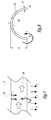
- the dispensing nozzle according to the invention is designated as a whole by reference numeral 1. As will be described more in the following, this nozzle comprises three distinct parts, namely an introduction portion 10, a dispersion portion 20, and a holding portion 30, the latter being optional.
- the nozzle 1 is intended to be mounted in a sheath 50, more particularly illustrated on the Figures 4 to 6 .
- the sheath 50 has sidewalls 51 and 52, as well as end walls 53 and 54.
- a sheath of cylindrical section can be used. This sheath allows the circulation of a gas stream, formed in this case by fumes 102 flowing vertically as is shown on the figure 4 .
- L is the useful length of the nozzle, namely the "penetrating" length of the nozzle inside the sheath. This length L corresponds to the distance separating the opposite side walls 51 and 52, between which the nozzle extends.
- the thickness e of the wall of this nozzle may be between 1 and 5 mm.
- the figure 4 presents a typical case of positioning in a sheath, in which the fumes circulate vertically downward. This is the preferred configuration, but the invention is perfectly usable for other configurations, and in particular if the fumes circulate horizontally in the sheath.
- the powdery product to be dispersed in the sheath, carried by a carrier fluid 101, is already suspended in this vector fluid by any means already known per se when it is admitted into the nozzle at a speed of between 10 and 30 m. / s, preferably between 15 and 25 m / s.
- the flow rate of pulverulent products is imposed, as is the flow rate of the carrier gas, so that the diameter of the portion of the nozzle is chosen so as to respect the speed range above.
- This part 10 is provided with a fixing means on the side wall 51 of the sheath 50.
- a fixing means is for example a flange 11 cooperating with the walls of an orifice 55 formed in the aforesaid wall, orifice in which is fitted part 10.
- the useful length 11 of this part 10 is between 10 and 30% of the total useful length L.
- the useful length of the introduction portion is relative to the area of this portion extending inside the sheath, namely to the right of the flange on the Figures 4 and 5 .
- the cylindrical introduction portion 10 is extended by a dispersion portion 20 in the form of a hollow cylinder section.
- This dispersion portion 20 is thus like a portion of tube, whose section forms a circular arc.
- this part is semi-cylindrical. However, it can be expected that it extends over an angular sector different from 180 °, with reference to an entire cylinder.
- this height is advantageously between 40 and 60% of the outer diameter D of the cylindrical portion 10, which corresponds to the diameter of the nozzle.
- This height h corresponds to the distance separating each free edge b1, b2 and the top of this portion 20.
- the length I2 of this portion 20 is advantageously between 60 and 90% of the total useful length L.
- this length I2 is advantageously greater than or equal to twice the length I1 of the part 10.
- the generatrix of the hemi-cylindrical part 20, facing the smoke, is denoted G.
- this generatrix called main
- this generatrix is therefore higher, namely that it is placed on the top of the portion 20.
- Orifices 22 are drilled in the portion 20, along the main generator G.
- the total section of these openings is between 2 and 15% of the cross section of the nozzle, defined as the diameter D multiplied by the total useful length L of this nozzle.
- these orifices have a circular shape, but may alternatively be constituted by a series of slots, or by a single slot extending along the main generator.
- the hemi-cylindrical part which acts as a shield, protects the flow from premature deflection and thus allows it to reach, in part, the zone C.
- the regular distribution of the powdery product over the entire active length of the nozzle is carried out by two phenomena, illustrated in Figures 7 and 8 .
- the hemi-cylindrical portion 20 is extended by a portion 30, said maintenance.
- the latter which may have a tubular cylindrical shape similar to that of the part 10, is used to attach the nozzle to the side wall 52.
- connection means of conventional type, between free end of this portion 30 and this wall 52.
- this portion 30 is optional, so that the dispersion portion 20 can directly be secured against the side wall 52.
- the holding portion 30 has a length I3 less than one third of the total length L of the nozzle and, preferably, less than one-fifth of this total length.
- a spray nozzle with a diameter D of 200 mm and a useful length L of 3 meters is used.
- the flue gases are flue gases and flow vertically downward at a speed of 15 m / s.
- the cylindrical introduction portion 10 of the nozzle which passes through the wall 51, is connected to a flange for fixing the outer side of the sheath.
- the cylindrical portion On the inner side of the sheath, the cylindrical portion has a useful length I1 of 300 mm.
- the hemi-cylindrical portion 20 extends over almost all of the remaining length, namely about 2500 mm. It is terminated by a cylindrical holding portion 30 whose length I3 is 200 mm.
Landscapes
- Engineering & Computer Science (AREA)
- Chemical & Material Sciences (AREA)
- Chemical Kinetics & Catalysis (AREA)
- Environmental & Geological Engineering (AREA)
- General Chemical & Material Sciences (AREA)
- Analytical Chemistry (AREA)
- Health & Medical Sciences (AREA)
- Oil, Petroleum & Natural Gas (AREA)
- Biomedical Technology (AREA)
- Mechanical Engineering (AREA)
- General Engineering & Computer Science (AREA)
- Dispersion Chemistry (AREA)
- Nozzles (AREA)
- Glanulating (AREA)
- Treating Waste Gases (AREA)
Claims (8)
- Düse (1) zum Verteilen von pulverförmigen Stoffen in einen Gasstrom, wobei die Düse (1) geeignet ist, in einen Kanal (50) zum Zirkulieren des Gasstroms montiert zu werden, indem sie sich längs im Inneren des Kanals über eine nützliche Länge (L), genannt nützliche Gesamtlänge, erstreckt, und die Düse (1) umfasst:- einen rohrförmigen Einführungsbereich (10) in zylindrischer Form, der dazu dient, in einer ersten Wand (51) des Kanals (50) befestigt zu werden, in einer Weise, dass er sich längs in das Innere des Kanals über eine nützliche Länge (l1) erstreckt, die zwischen 10 und 30% der nützlichen Gesamtlänge (L) liegt,- einen Verteilungsbereich (20) in Form eines Teils eines Hohlzylinders, dessen Querschnitt einen Kreisbogen bildet, der sich in der Verlängerung des Einführungsbereichs erstreckt, wobei dieser Verteilungsbereich mit Öffnungen (22) für den Durchgang von Rauchgasen durchbohrt ist, die entlang einer Mantellinie (G), genannt Hauptmantellinie, des Verteilungsbereichs liegen, die vorgesehen ist, dem Gasstrom zugewandt zu sein, wobei die Öffnungen einen Gesamtquerschnitt zwischen 2 und 15% des wirksamen Querschnitts der Düse aufweisen, entsprechend der nützlichen Gesamtlänge (L) multipliziert mit dem Außendurchmesser (D) des Einführungsbereichs (10), wobei dieser Verteilungsbereich (20) eine Länge (l2) aufweist, die größer oder gleich dem Doppelten der nützlichen Länge (l1) des Einführungsbereichs (10) ist.
- Düse nach Anspruch 1, dadurch gekennzeichnet, dass der Verteilungsbereich (20) halbzylindrisch ist.
- Düse nach einem der Ansprüche 1 oder 2, dadurch gekennzeichnet, dass der Verteilungsbereich (20) eine Höhe (h) aufweist, die zwischen 40 und 60% des Außendurchmessers (D) der Düse (1) ist, wobei diese Höhe (h) dem Abstand entspricht, der die Hauptmantellinie (G) von den freien Rändern (b1, b2) des Verteilungsbereichs trennt.
- Düse nach einem der vorhergehenden Ansprüche, dadurch gekennzeichnet, dass der Verteilungsbereich (20) entgegengesetzt zum Einführungsbereich (10) durch einen Bereich (30) zum Halten gegen eine entgegengesetzte Wand (52) des Kanals (50) endet, wobei dieser Haltebereich (30) eine Länge (l3) aufweist, die kleiner als ein Drittel der nützlichen Gesamtlänge (L) ist.
- Düse nach einem der vorhergehenden Ansprüche, dadurch gekennzeichnet, dass der Verteilungsbereich (20) eine Länge (l2) aufweist, die zwischen 60 und 90% der nützlichen Gesamtlänge (L) liegt.
- Düse nach einem der vorhergehenden Ansprüche, dadurch gekennzeichnet, dass die Öffnungen (22) für den Durchgang der Rauchgase eine Kreisform aufweisen.
- System mit einem Kanal (50) für die Zirkulation eines Gasstroms und einer Düse (1) für die Verteilung von pulverförmigen Stoffen entsprechend einem beliebigen der Ansprüche 1 bis 6 und die in den Kanal montiert ist.
- Verfahren zur Realisierung einer Düse nach einem beliebigen der Ansprüche 1 bis 6, bei dem pulverförmige Stoffe mitten in einem Trägerfluid im Inneren einer Düse zirkuliert werden bei einer Geschwindigkeit, die zwischen 10 und 30 m/s und vorzugsweise zwischen 15 und 20 m/s liegt, wobei diese Geschwindigkeit am Einführungsbereich (10) gemessen wird.
Priority Applications (1)
| Application Number | Priority Date | Filing Date | Title |
|---|---|---|---|
| PL10171843T PL2292314T3 (pl) | 2009-08-05 | 2010-08-04 | Dysza do rozprowadzania sproszkowanych produktów w strumieniu gazowym i sposób jej stosowania |
Applications Claiming Priority (1)
| Application Number | Priority Date | Filing Date | Title |
|---|---|---|---|
| FR0955507A FR2948886B1 (fr) | 2009-08-05 | 2009-08-05 | Buse de distribution de produits pulverulents dans une veine gazeuse et son procede de mise en oeuvre |
Publications (2)
| Publication Number | Publication Date |
|---|---|
| EP2292314A1 EP2292314A1 (de) | 2011-03-09 |
| EP2292314B1 true EP2292314B1 (de) | 2012-07-25 |
Family
ID=41587396
Family Applications (1)
| Application Number | Title | Priority Date | Filing Date |
|---|---|---|---|
| EP10171843A Active EP2292314B1 (de) | 2009-08-05 | 2010-08-04 | Düse zum Verteilen von pulverförmigen Produkten in einer Gasleitung und ihr Verfahren zur Anwendung& xA; |
Country Status (6)
| Country | Link |
|---|---|
| EP (1) | EP2292314B1 (de) |
| DK (1) | DK2292314T3 (de) |
| ES (1) | ES2391622T3 (de) |
| FR (1) | FR2948886B1 (de) |
| PL (1) | PL2292314T3 (de) |
| PT (1) | PT2292314E (de) |
Family Cites Families (5)
| Publication number | Priority date | Publication date | Assignee | Title |
|---|---|---|---|---|
| DE2432515A1 (de) * | 1974-07-04 | 1976-01-22 | Wiggins Teape Res Dev | Verfahren zum verringern der emission schwefelhaltiger verbindungen von oefen |
| US5048431A (en) * | 1986-07-14 | 1991-09-17 | Inland Steel Company | Method and apparatus for reducing sulfur dioxide content in flue gases |
| US20040244382A1 (en) * | 1992-10-27 | 2004-12-09 | Hagen David L. | Distributed direct fluid contactor |
| AU2003284210A1 (en) * | 2002-10-15 | 2004-05-04 | Vast Power Systems, Inc. | Method and apparatus for mixing fluids |
| GB2429937A (en) * | 2005-09-08 | 2007-03-14 | Siemens Ind Turbomachinery Ltd | Apparatus for mixing gas streams |
-
2009
- 2009-08-05 FR FR0955507A patent/FR2948886B1/fr not_active Expired - Fee Related
-
2010
- 2010-08-04 EP EP10171843A patent/EP2292314B1/de active Active
- 2010-08-04 DK DK10171843.5T patent/DK2292314T3/da active
- 2010-08-04 ES ES10171843T patent/ES2391622T3/es active Active
- 2010-08-04 PL PL10171843T patent/PL2292314T3/pl unknown
- 2010-08-04 PT PT10171843T patent/PT2292314E/pt unknown
Also Published As
| Publication number | Publication date |
|---|---|
| FR2948886A1 (fr) | 2011-02-11 |
| FR2948886B1 (fr) | 2013-03-29 |
| ES2391622T3 (es) | 2012-11-28 |
| PL2292314T3 (pl) | 2012-11-30 |
| EP2292314A1 (de) | 2011-03-09 |
| PT2292314E (pt) | 2012-08-22 |
| DK2292314T3 (da) | 2012-08-27 |
Similar Documents
| Publication | Publication Date | Title |
|---|---|---|
| BE1016382A3 (fr) | Dispositif d'injection de fluides a l'interieur d'un lit fluidifie rotatif. | |
| EP0417009B1 (de) | Vorrichtung und Anlage zur Reinigung von Abzugskanälen, insbesondere bei Erdölbohrlöchern | |
| FR2550469A1 (fr) | Injecteur de microbulles | |
| EP2085488B1 (de) | Device for blowing gas onto a surface of a material in running strips | |
| FR2575678A1 (fr) | Ejecteur pneumatique de poudre | |
| FR2967595A1 (fr) | Dispositif de collecte de poussiere pour machine a decouper le beton | |
| EP1044064B1 (de) | Vorrichtung zur umhüllung von granulaten zur oralen aufnahme | |
| EP0219882B1 (de) | Verfahren und automatische Vorrichtung zum Reinigen eines Wärmetauschers für gasförmige Fluide | |
| EP0013230B1 (de) | Vorrichtung zum Entfernen einer Flüssigkeit von der Oberfläche eines langen, sich kontinuierlich bewegenden Produktes | |
| EP2292314B1 (de) | Düse zum Verteilen von pulverförmigen Produkten in einer Gasleitung und ihr Verfahren zur Anwendung& xA; | |
| EP0191485A1 (de) | Homogenisierungsanlage für eine in einer Kanalisation transportierte Flüssigkeit | |
| CA1285374C (fr) | Dispositif pour l'alimentation des ouvertures d'une grille de fluidisation en gaz de decolmatage | |
| EP1152967B1 (de) | Vorrichtung zum dispergieren von schüttgut im innenraum eines behälters | |
| WO2000021693A1 (fr) | Dispositif et lance agitateur hydrodynamique | |
| FR2594045A1 (fr) | Filtre auto-nettoyant, et boite a eau d'entree de condenseur de vapeur comportant un tel filtre. | |
| FR2899438A1 (fr) | Dispositif pour separer les uns des autres le pedoncules de fruits regroupes en grappes. | |
| FR2594044A1 (fr) | Filtre auto-nettoyant. | |
| WO2022135756A1 (fr) | Module destiné à être employé dans un système de tri par taille de particules expulsées par centrifugation, système de tri et procédé de configuration d'un tel système | |
| EP3946810A1 (de) | Düse für ein sprühsystem und sprühsystem mit einer solchen düse | |
| FR3002990A1 (fr) | Dispositif d'ejection de matiere granuleuse a venturi | |
| EP2900053B1 (de) | Bewässerungsvorrichtung mit selbstregulierendem durchfluss und verwendung | |
| EP3328516B1 (de) | Vorrichtung zum fangen von partikeln in einem gasstrom | |
| FR2583652A1 (fr) | Perfectionnement aux tours de refroidissement des gaz charges de poussieres | |
| FR2883770A1 (fr) | Dispositif ameliore de chromatographie de partage centrifuge a cellules | |
| FR2983093A1 (fr) | Dispositif de collecte electrostatique de particules en suspension dans un milieu gazeux |
Legal Events
| Date | Code | Title | Description |
|---|---|---|---|
| PUAI | Public reference made under article 153(3) epc to a published international application that has entered the european phase |
Free format text: ORIGINAL CODE: 0009012 |
|
| AK | Designated contracting states |
Kind code of ref document: A1 Designated state(s): AL AT BE BG CH CY CZ DE DK EE ES FI FR GB GR HR HU IE IS IT LI LT LU LV MC MK MT NL NO PL PT RO SE SI SK SM TR |
|
| AX | Request for extension of the european patent |
Extension state: BA ME RS |
|
| 17P | Request for examination filed |
Effective date: 20110621 |
|
| GRAP | Despatch of communication of intention to grant a patent |
Free format text: ORIGINAL CODE: EPIDOSNIGR1 |
|
| RIC1 | Information provided on ipc code assigned before grant |
Ipc: F23J 7/00 20060101ALI20120203BHEP Ipc: B01F 3/06 20060101ALI20120203BHEP Ipc: B01D 53/76 20060101ALI20120203BHEP Ipc: F23J 15/04 20060101ALI20120203BHEP Ipc: F23J 15/00 20060101ALI20120203BHEP Ipc: B01D 53/68 20060101ALI20120203BHEP Ipc: B01D 53/50 20060101AFI20120203BHEP Ipc: B01F 5/04 20060101ALI20120203BHEP |
|
| RAP1 | Party data changed (applicant data changed or rights of an application transferred) |
Owner name: LAB SA |
|
| GRAS | Grant fee paid |
Free format text: ORIGINAL CODE: EPIDOSNIGR3 |
|
| GRAA | (expected) grant |
Free format text: ORIGINAL CODE: 0009210 |
|
| AK | Designated contracting states |
Kind code of ref document: B1 Designated state(s): AL AT BE BG CH CY CZ DE DK EE ES FI FR GB GR HR HU IE IS IT LI LT LU LV MC MK MT NL NO PL PT RO SE SI SK SM TR |
|
| REG | Reference to a national code |
Ref country code: GB Ref legal event code: FG4D Free format text: NOT ENGLISH |
|
| REG | Reference to a national code |
Ref country code: CH Ref legal event code: EP |
|
| REG | Reference to a national code |
Ref country code: IE Ref legal event code: FG4D Free format text: LANGUAGE OF EP DOCUMENT: FRENCH Ref country code: AT Ref legal event code: REF Ref document number: 567465 Country of ref document: AT Kind code of ref document: T Effective date: 20120815 |
|
| REG | Reference to a national code |
Ref country code: PT Ref legal event code: SC4A Free format text: AVAILABILITY OF NATIONAL TRANSLATION Effective date: 20120814 |
|
| REG | Reference to a national code |
Ref country code: DK Ref legal event code: T3 |
|
| REG | Reference to a national code |
Ref country code: DE Ref legal event code: R096 Ref document number: 602010002281 Country of ref document: DE Effective date: 20120920 |
|
| REG | Reference to a national code |
Ref country code: SE Ref legal event code: TRGR |
|
| REG | Reference to a national code |
Ref country code: NL Ref legal event code: T3 |
|
| REG | Reference to a national code |
Ref country code: ES Ref legal event code: FG2A Ref document number: 2391622 Country of ref document: ES Kind code of ref document: T3 Effective date: 20121128 |
|
| REG | Reference to a national code |
Ref country code: PL Ref legal event code: T3 |
|
| REG | Reference to a national code |
Ref country code: LT Ref legal event code: MG4D Effective date: 20120725 |
|
| PG25 | Lapsed in a contracting state [announced via postgrant information from national office to epo] |
Ref country code: HR Free format text: LAPSE BECAUSE OF FAILURE TO SUBMIT A TRANSLATION OF THE DESCRIPTION OR TO PAY THE FEE WITHIN THE PRESCRIBED TIME-LIMIT Effective date: 20120725 Ref country code: LT Free format text: LAPSE BECAUSE OF FAILURE TO SUBMIT A TRANSLATION OF THE DESCRIPTION OR TO PAY THE FEE WITHIN THE PRESCRIBED TIME-LIMIT Effective date: 20120725 Ref country code: IS Free format text: LAPSE BECAUSE OF FAILURE TO SUBMIT A TRANSLATION OF THE DESCRIPTION OR TO PAY THE FEE WITHIN THE PRESCRIBED TIME-LIMIT Effective date: 20121125 Ref country code: CY Free format text: LAPSE BECAUSE OF FAILURE TO SUBMIT A TRANSLATION OF THE DESCRIPTION OR TO PAY THE FEE WITHIN THE PRESCRIBED TIME-LIMIT Effective date: 20120725 Ref country code: FI Free format text: LAPSE BECAUSE OF FAILURE TO SUBMIT A TRANSLATION OF THE DESCRIPTION OR TO PAY THE FEE WITHIN THE PRESCRIBED TIME-LIMIT Effective date: 20120725 Ref country code: NO Free format text: LAPSE BECAUSE OF FAILURE TO SUBMIT A TRANSLATION OF THE DESCRIPTION OR TO PAY THE FEE WITHIN THE PRESCRIBED TIME-LIMIT Effective date: 20121025 |
|
| PG25 | Lapsed in a contracting state [announced via postgrant information from national office to epo] |
Ref country code: LV Free format text: LAPSE BECAUSE OF FAILURE TO SUBMIT A TRANSLATION OF THE DESCRIPTION OR TO PAY THE FEE WITHIN THE PRESCRIBED TIME-LIMIT Effective date: 20120725 Ref country code: GR Free format text: LAPSE BECAUSE OF FAILURE TO SUBMIT A TRANSLATION OF THE DESCRIPTION OR TO PAY THE FEE WITHIN THE PRESCRIBED TIME-LIMIT Effective date: 20121026 Ref country code: SI Free format text: LAPSE BECAUSE OF FAILURE TO SUBMIT A TRANSLATION OF THE DESCRIPTION OR TO PAY THE FEE WITHIN THE PRESCRIBED TIME-LIMIT Effective date: 20120725 |
|
| PG25 | Lapsed in a contracting state [announced via postgrant information from national office to epo] |
Ref country code: MC Free format text: LAPSE BECAUSE OF NON-PAYMENT OF DUE FEES Effective date: 20120831 |
|
| PG25 | Lapsed in a contracting state [announced via postgrant information from national office to epo] |
Ref country code: CZ Free format text: LAPSE BECAUSE OF FAILURE TO SUBMIT A TRANSLATION OF THE DESCRIPTION OR TO PAY THE FEE WITHIN THE PRESCRIBED TIME-LIMIT Effective date: 20120725 Ref country code: RO Free format text: LAPSE BECAUSE OF FAILURE TO SUBMIT A TRANSLATION OF THE DESCRIPTION OR TO PAY THE FEE WITHIN THE PRESCRIBED TIME-LIMIT Effective date: 20120725 Ref country code: EE Free format text: LAPSE BECAUSE OF FAILURE TO SUBMIT A TRANSLATION OF THE DESCRIPTION OR TO PAY THE FEE WITHIN THE PRESCRIBED TIME-LIMIT Effective date: 20120725 |
|
| REG | Reference to a national code |
Ref country code: IE Ref legal event code: MM4A |
|
| PG25 | Lapsed in a contracting state [announced via postgrant information from national office to epo] |
Ref country code: SK Free format text: LAPSE BECAUSE OF FAILURE TO SUBMIT A TRANSLATION OF THE DESCRIPTION OR TO PAY THE FEE WITHIN THE PRESCRIBED TIME-LIMIT Effective date: 20120725 |
|
| PLBE | No opposition filed within time limit |
Free format text: ORIGINAL CODE: 0009261 |
|
| STAA | Information on the status of an ep patent application or granted ep patent |
Free format text: STATUS: NO OPPOSITION FILED WITHIN TIME LIMIT |
|
| 26N | No opposition filed |
Effective date: 20130426 |
|
| PG25 | Lapsed in a contracting state [announced via postgrant information from national office to epo] |
Ref country code: BG Free format text: LAPSE BECAUSE OF FAILURE TO SUBMIT A TRANSLATION OF THE DESCRIPTION OR TO PAY THE FEE WITHIN THE PRESCRIBED TIME-LIMIT Effective date: 20121025 Ref country code: IE Free format text: LAPSE BECAUSE OF NON-PAYMENT OF DUE FEES Effective date: 20120804 |
|
| REG | Reference to a national code |
Ref country code: DE Ref legal event code: R097 Ref document number: 602010002281 Country of ref document: DE Effective date: 20130426 |
|
| PG25 | Lapsed in a contracting state [announced via postgrant information from national office to epo] |
Ref country code: MT Free format text: LAPSE BECAUSE OF FAILURE TO SUBMIT A TRANSLATION OF THE DESCRIPTION OR TO PAY THE FEE WITHIN THE PRESCRIBED TIME-LIMIT Effective date: 20120725 Ref country code: AL Free format text: LAPSE BECAUSE OF FAILURE TO SUBMIT A TRANSLATION OF THE DESCRIPTION OR TO PAY THE FEE WITHIN THE PRESCRIBED TIME-LIMIT Effective date: 20120725 |
|
| PG25 | Lapsed in a contracting state [announced via postgrant information from national office to epo] |
Ref country code: TR Free format text: LAPSE BECAUSE OF FAILURE TO SUBMIT A TRANSLATION OF THE DESCRIPTION OR TO PAY THE FEE WITHIN THE PRESCRIBED TIME-LIMIT Effective date: 20120725 |
|
| PG25 | Lapsed in a contracting state [announced via postgrant information from national office to epo] |
Ref country code: SM Free format text: LAPSE BECAUSE OF FAILURE TO SUBMIT A TRANSLATION OF THE DESCRIPTION OR TO PAY THE FEE WITHIN THE PRESCRIBED TIME-LIMIT Effective date: 20120725 Ref country code: LU Free format text: LAPSE BECAUSE OF NON-PAYMENT OF DUE FEES Effective date: 20120804 |
|
| PG25 | Lapsed in a contracting state [announced via postgrant information from national office to epo] |
Ref country code: HU Free format text: LAPSE BECAUSE OF FAILURE TO SUBMIT A TRANSLATION OF THE DESCRIPTION OR TO PAY THE FEE WITHIN THE PRESCRIBED TIME-LIMIT Effective date: 20100804 |
|
| PG25 | Lapsed in a contracting state [announced via postgrant information from national office to epo] |
Ref country code: MK Free format text: LAPSE BECAUSE OF FAILURE TO SUBMIT A TRANSLATION OF THE DESCRIPTION OR TO PAY THE FEE WITHIN THE PRESCRIBED TIME-LIMIT Effective date: 20120725 |
|
| REG | Reference to a national code |
Ref country code: FR Ref legal event code: PLFP Year of fee payment: 7 |
|
| REG | Reference to a national code |
Ref country code: FR Ref legal event code: PLFP Year of fee payment: 8 |
|
| REG | Reference to a national code |
Ref country code: FR Ref legal event code: PLFP Year of fee payment: 9 |
|
| P01 | Opt-out of the competence of the unified patent court (upc) registered |
Effective date: 20230516 |
|
| PGFP | Annual fee paid to national office [announced via postgrant information from national office to epo] |
Ref country code: NL Payment date: 20230726 Year of fee payment: 14 |
|
| PGFP | Annual fee paid to national office [announced via postgrant information from national office to epo] |
Ref country code: IT Payment date: 20230809 Year of fee payment: 14 Ref country code: GB Payment date: 20230824 Year of fee payment: 14 Ref country code: ES Payment date: 20230907 Year of fee payment: 14 Ref country code: CH Payment date: 20230902 Year of fee payment: 14 Ref country code: AT Payment date: 20230724 Year of fee payment: 14 |
|
| PGFP | Annual fee paid to national office [announced via postgrant information from national office to epo] |
Ref country code: SE Payment date: 20230816 Year of fee payment: 14 Ref country code: PT Payment date: 20230719 Year of fee payment: 14 Ref country code: PL Payment date: 20230720 Year of fee payment: 14 Ref country code: DK Payment date: 20230728 Year of fee payment: 14 Ref country code: DE Payment date: 20230808 Year of fee payment: 14 Ref country code: BE Payment date: 20230822 Year of fee payment: 14 |
|
| REG | Reference to a national code |
Ref country code: DE Ref legal event code: R119 Ref document number: 602010002281 Country of ref document: DE |
|
| REG | Reference to a national code |
Ref country code: DK Ref legal event code: EBP Effective date: 20240831 |
|
| REG | Reference to a national code |
Ref country code: CH Ref legal event code: PL |
|
| REG | Reference to a national code |
Ref country code: SE Ref legal event code: EUG |
|
| REG | Reference to a national code |
Ref country code: NL Ref legal event code: MM Effective date: 20240901 |
|
| PG25 | Lapsed in a contracting state [announced via postgrant information from national office to epo] |
Ref country code: PT Free format text: LAPSE BECAUSE OF NON-PAYMENT OF DUE FEES Effective date: 20250204 |
|
| REG | Reference to a national code |
Ref country code: AT Ref legal event code: MM01 Ref document number: 567465 Country of ref document: AT Kind code of ref document: T Effective date: 20240804 |
|
| GBPC | Gb: european patent ceased through non-payment of renewal fee |
Effective date: 20240804 |
|
| PG25 | Lapsed in a contracting state [announced via postgrant information from national office to epo] |
Ref country code: AT Free format text: LAPSE BECAUSE OF NON-PAYMENT OF DUE FEES Effective date: 20240804 Ref country code: CH Free format text: LAPSE BECAUSE OF NON-PAYMENT OF DUE FEES Effective date: 20240831 |
|
| PG25 | Lapsed in a contracting state [announced via postgrant information from national office to epo] |
Ref country code: NL Free format text: LAPSE BECAUSE OF NON-PAYMENT OF DUE FEES Effective date: 20240901 |
|
| REG | Reference to a national code |
Ref country code: BE Ref legal event code: MM Effective date: 20240831 |
|
| PG25 | Lapsed in a contracting state [announced via postgrant information from national office to epo] |
Ref country code: DE Free format text: LAPSE BECAUSE OF NON-PAYMENT OF DUE FEES Effective date: 20250301 |
|
| PG25 | Lapsed in a contracting state [announced via postgrant information from national office to epo] |
Ref country code: GB Free format text: LAPSE BECAUSE OF NON-PAYMENT OF DUE FEES Effective date: 20240804 Ref country code: DK Free format text: LAPSE BECAUSE OF NON-PAYMENT OF DUE FEES Effective date: 20240831 |
|
| PG25 | Lapsed in a contracting state [announced via postgrant information from national office to epo] |
Ref country code: BE Free format text: LAPSE BECAUSE OF NON-PAYMENT OF DUE FEES Effective date: 20240831 Ref country code: IT Free format text: LAPSE BECAUSE OF NON-PAYMENT OF DUE FEES Effective date: 20240804 |
|
| REG | Reference to a national code |
Ref country code: ES Ref legal event code: FD2A Effective date: 20250926 |
|
| PG25 | Lapsed in a contracting state [announced via postgrant information from national office to epo] |
Ref country code: ES Free format text: LAPSE BECAUSE OF NON-PAYMENT OF DUE FEES Effective date: 20240805 |
|
| PG25 | Lapsed in a contracting state [announced via postgrant information from national office to epo] |
Ref country code: SE Free format text: LAPSE BECAUSE OF NON-PAYMENT OF DUE FEES Effective date: 20240805 |
|
| PGFP | Annual fee paid to national office [announced via postgrant information from national office to epo] |
Ref country code: FR Payment date: 20250710 Year of fee payment: 16 |
|
| PG25 | Lapsed in a contracting state [announced via postgrant information from national office to epo] |
Ref country code: PL Free format text: LAPSE BECAUSE OF NON-PAYMENT OF DUE FEES Effective date: 20240804 |