EP2292321A1 - Anlage zur Herstellung eines homogenen Gasgemischs aus flüssigen und gasförmigen Bestandteilen - Google Patents
Anlage zur Herstellung eines homogenen Gasgemischs aus flüssigen und gasförmigen Bestandteilen Download PDFInfo
- Publication number
- EP2292321A1 EP2292321A1 EP10172361A EP10172361A EP2292321A1 EP 2292321 A1 EP2292321 A1 EP 2292321A1 EP 10172361 A EP10172361 A EP 10172361A EP 10172361 A EP10172361 A EP 10172361A EP 2292321 A1 EP2292321 A1 EP 2292321A1
- Authority
- EP
- European Patent Office
- Prior art keywords
- loop
- mixer
- installation according
- liquid
- outlet
- Prior art date
- Legal status (The legal status is an assumption and is not a legal conclusion. Google has not performed a legal analysis and makes no representation as to the accuracy of the status listed.)
- Granted
Links
Images


Classifications
-
- B—PERFORMING OPERATIONS; TRANSPORTING
- B01—PHYSICAL OR CHEMICAL PROCESSES OR APPARATUS IN GENERAL
- B01F—MIXING, e.g. DISSOLVING, EMULSIFYING OR DISPERSING
- B01F23/00—Mixing according to the phases to be mixed, e.g. dispersing or emulsifying
- B01F23/20—Mixing gases with liquids
- B01F23/23—Mixing gases with liquids by introducing gases into liquid media, e.g. for producing aerated liquids
- B01F23/232—Mixing gases with liquids by introducing gases into liquid media, e.g. for producing aerated liquids using flow-mixing means for introducing the gases, e.g. baffles
- B01F23/2323—Mixing gases with liquids by introducing gases into liquid media, e.g. for producing aerated liquids using flow-mixing means for introducing the gases, e.g. baffles by circulating the flow in guiding constructions or conduits
-
- B—PERFORMING OPERATIONS; TRANSPORTING
- B01—PHYSICAL OR CHEMICAL PROCESSES OR APPARATUS IN GENERAL
- B01F—MIXING, e.g. DISSOLVING, EMULSIFYING OR DISPERSING
- B01F23/00—Mixing according to the phases to be mixed, e.g. dispersing or emulsifying
- B01F23/20—Mixing gases with liquids
- B01F23/23—Mixing gases with liquids by introducing gases into liquid media, e.g. for producing aerated liquids
- B01F23/236—Mixing gases with liquids by introducing gases into liquid media, e.g. for producing aerated liquids specially adapted for aerating or carbonating beverages
- B01F23/2362—Mixing gases with liquids by introducing gases into liquid media, e.g. for producing aerated liquids specially adapted for aerating or carbonating beverages for aerating or carbonating within receptacles or tanks, e.g. distribution machines
-
- B—PERFORMING OPERATIONS; TRANSPORTING
- B01—PHYSICAL OR CHEMICAL PROCESSES OR APPARATUS IN GENERAL
- B01F—MIXING, e.g. DISSOLVING, EMULSIFYING OR DISPERSING
- B01F23/00—Mixing according to the phases to be mixed, e.g. dispersing or emulsifying
- B01F23/20—Mixing gases with liquids
- B01F23/23—Mixing gases with liquids by introducing gases into liquid media, e.g. for producing aerated liquids
- B01F23/236—Mixing gases with liquids by introducing gases into liquid media, e.g. for producing aerated liquids specially adapted for aerating or carbonating beverages
- B01F23/2363—Mixing systems, i.e. flow charts or diagrams; Arrangements, e.g. comprising controlling means
-
- B—PERFORMING OPERATIONS; TRANSPORTING
- B01—PHYSICAL OR CHEMICAL PROCESSES OR APPARATUS IN GENERAL
- B01F—MIXING, e.g. DISSOLVING, EMULSIFYING OR DISPERSING
- B01F25/00—Flow mixers; Mixers for falling materials, e.g. solid particles
- B01F25/20—Jet mixers, i.e. mixers using high-speed fluid streams
- B01F25/21—Jet mixers, i.e. mixers using high-speed fluid streams with submerged injectors, e.g. nozzles, for injecting high-pressure jets into a large volume or into mixing chambers
- B01F25/211—Jet mixers, i.e. mixers using high-speed fluid streams with submerged injectors, e.g. nozzles, for injecting high-pressure jets into a large volume or into mixing chambers the injectors being surrounded by guiding tubes
-
- B—PERFORMING OPERATIONS; TRANSPORTING
- B01—PHYSICAL OR CHEMICAL PROCESSES OR APPARATUS IN GENERAL
- B01F—MIXING, e.g. DISSOLVING, EMULSIFYING OR DISPERSING
- B01F25/00—Flow mixers; Mixers for falling materials, e.g. solid particles
- B01F25/30—Injector mixers
- B01F25/31—Injector mixers in conduits or tubes through which the main component flows
- B01F25/313—Injector mixers in conduits or tubes through which the main component flows wherein additional components are introduced in the centre of the conduit
- B01F25/3131—Injector mixers in conduits or tubes through which the main component flows wherein additional components are introduced in the centre of the conduit with additional mixing means other than injector mixers, e.g. screens, baffles or rotating elements
-
- B—PERFORMING OPERATIONS; TRANSPORTING
- B01—PHYSICAL OR CHEMICAL PROCESSES OR APPARATUS IN GENERAL
- B01F—MIXING, e.g. DISSOLVING, EMULSIFYING OR DISPERSING
- B01F25/00—Flow mixers; Mixers for falling materials, e.g. solid particles
- B01F25/40—Static mixers
- B01F25/44—Mixers in which the components are pressed through slits
- B01F25/441—Mixers in which the components are pressed through slits characterised by the configuration of the surfaces forming the slits
- B01F25/4416—Mixers in which the components are pressed through slits characterised by the configuration of the surfaces forming the slits the opposed surfaces being provided with grooves
- B01F25/44162—Circumferential grooves formed on opposed surfaces, e.g. on planar surfaces or on cylinders or cones
-
- B—PERFORMING OPERATIONS; TRANSPORTING
- B01—PHYSICAL OR CHEMICAL PROCESSES OR APPARATUS IN GENERAL
- B01F—MIXING, e.g. DISSOLVING, EMULSIFYING OR DISPERSING
- B01F25/00—Flow mixers; Mixers for falling materials, e.g. solid particles
- B01F25/40—Static mixers
- B01F25/44—Mixers in which the components are pressed through slits
- B01F25/442—Mixers in which the components are pressed through slits characterised by the relative position of the surfaces during operation
- B01F25/4422—Mixers in which the components are pressed through slits characterised by the relative position of the surfaces during operation the surfaces being maintained in a fixed but adjustable position, spaced from each other, therefore allowing the slit spacing to be varied
-
- B—PERFORMING OPERATIONS; TRANSPORTING
- B01—PHYSICAL OR CHEMICAL PROCESSES OR APPARATUS IN GENERAL
- B01F—MIXING, e.g. DISSOLVING, EMULSIFYING OR DISPERSING
- B01F25/00—Flow mixers; Mixers for falling materials, e.g. solid particles
- B01F25/50—Circulation mixers, e.g. wherein at least part of the mixture is discharged from and reintroduced into a receptacle
- B01F25/51—Circulation mixers, e.g. wherein at least part of the mixture is discharged from and reintroduced into a receptacle in which the mixture is circulated through a set of tubes, e.g. with gradual introduction of a component into the circulating flow
-
- B—PERFORMING OPERATIONS; TRANSPORTING
- B01—PHYSICAL OR CHEMICAL PROCESSES OR APPARATUS IN GENERAL
- B01F—MIXING, e.g. DISSOLVING, EMULSIFYING OR DISPERSING
- B01F33/00—Other mixers; Mixing plants; Combinations of mixers
- B01F33/80—Mixing plants; Combinations of mixers
- B01F33/82—Combinations of dissimilar mixers
- B01F33/821—Combinations of dissimilar mixers with consecutive receptacles
-
- B—PERFORMING OPERATIONS; TRANSPORTING
- B01—PHYSICAL OR CHEMICAL PROCESSES OR APPARATUS IN GENERAL
- B01F—MIXING, e.g. DISSOLVING, EMULSIFYING OR DISPERSING
- B01F2101/00—Mixing characterised by the nature of the mixed materials or by the application field
- B01F2101/06—Mixing of food ingredients
- B01F2101/14—Mixing of ingredients for non-alcoholic beverages; Dissolving sugar in water
Definitions
- the operation of the device is not optimal.
- the object of the invention is, above all, to propose an installation improving the homogeneity of the mixture and the stability of the gas saturation, and reducing or eliminating the problems of cavitation in the mixer.
- an installation of the kind defined above is characterized in that the mixer is a static mixer with turbulence rings, comprising one or more stages as a function of the overall pressure drop to be obtained, with adjustment of the manual pressure losses. or automatic.
- the mixer comprises a body and a movable core (and has at least two rings of turbulence.
- the inner wall of the body of the mixer is provided with at least two grooves and two seats, while the wall of the core comprises at least two flanges in the form of movable flaps and at least two grooves complementary to those of the body, each body / core groove assembly comprising a valve and a seat reducing the passage section followed by a ring of turbulence itself, the groove shapes being provided to create the minimum pressure drop with a rapid rotation of the fluid in all core positions, creating less cavitation at the exit of the seat.
- the turbulence rings can be made to obtain in each ring a cycle of fluid velocity variation having an acceleration and a reduction as regular as possible, the entry into the conical seat being effected radially from the outside towards the inside. to reach the ring of turbulence.
- the mixer comprises an adjustment means, in particular screw, or with a pneumatic jack with scrolling membrane, to allow to adjust manually or by an automatism the position of the core relative to the body.
- a multi-stage mixer may be provided with a common adjustment means for adjusting the pressure losses of the downstream stage.
- Different cores can be provided for each stage so that the pressure losses of each stage are decreasing, from upstream to downstream, so as not to destabilize the product at the mixer outlet in the zone of lower pressure.
- the installation comprises a 3-way valve with three ports (two inputs and one output), the inputs being connected to the mixer output loop and upstream of the output connection, the other on arrival of product in the loop input connection, while the output of the 3-way valve is connected to the loop in the direction of the loop pump.
- the installation comprises a 4-way valve with four orifices (two inputs respectively aligned with two outputs), the inputs being connected to the loop upstream of the output branch, the other to the arrival of product in the input branch of the loop, while an output of the 4-way valve is connected to the loop in the direction of the loop pump, the other output is connected to the supply line of the loop.
- extraction machine the valve moving in a right-angled bore of the inlet / outlet alignments and being provided with V-slots at its periphery to ensure a pressure drop depending on, in particular proportional to, its opening.
- the 3-way or 4-way valve is intended to ensure: a mixture of the recycled product in the loop and the raw product entering; a pressure as constant as possible in output; a non-return function to prevent the direct passage from the inlet to the outlet in certain phases of operation.
- the 3-way or 4-way valve can be equipped, depending on the type of loop, with manual or pneumatic control.
- the 3-way or 4-way valve may be provided with a piston cylinder with a scrolling diaphragm for its adjustment, the active membrane section being preferably substantially equal to the active section of the valve to instantly ensure a substantially constant pressure on the outgoing liquid. of the loop.
- the saturator is disposed upstream of the suction of the pump and connected thereto by a short straight pipe section.
- the installation comprises a dynamic capacity to adapt the loop volume to the needs in order to smooth the slight dosing variations due to the regulation and to obtain a homogeneous product for the live feed of a bottling machine .
- the dynamic capacity may comprise a cylindrical envelope of greater diameter than that of the rest of the pipe of the loop, at least one mixing nozzle in inner form of venturi and cylindrical outer, disposed in the envelope, the dynamic capacity being equipped with one or more mixing nozzles arranged to create a suction effect and to ensure intensive stirring of the liquid by rapid convection with liquid return to the sides of the nozzle (s).
- the installation may comprise a modulating output valve controlled by a regulation to regulate the outflow necessary to supply the extraction machine, according to its level according to the feeding mode of the extraction machine (alternatively see 4-way valve ARV-E).
- a regulation controls the flow rate of the injected gas, measured by a mass flow meter, in proportion to the flow rate used, measured by a precision precision flowmeter in order to ensure an accurate metering of the gas at all times.
- the installation may comprise one or more modulating valves depending on the number of additives to be injected and one or more corresponding flowmeters for proportional dosing to the useful flow rate.
- the dynamic loop is located in a vertical plane.
- the internal volume of the dynamic loop corresponds to the volume necessary to ensure regular dosing of the components.
- the pump is characterized by a high suction capacity and a high discharge pressure, in particular from 5 to 15 bar (possibility of multistage or volumetric pump).
- the pump or pumps can be volumetric pumps controlled by frequency variation.
- the base product 1 consisting for example of a mixture of the driving product, such as water, and additives, in particular sweeteners
- the base product is supplied to the INS facility using a feed pump 2 which delivers the base product according to a pressure determined by an automaton 3 for the type of draw or pulling machine (not shown) and conditioned liquid.
- the final product flow is withdrawn into line 4 connected to the printer.
- the pressure in line 4 is supplied as an adjustment parameter to PLC 3.
- the ARV-D 3-way valve is equipped, depending on the type of loop, with a pneumatic control 10 illustrated on Fig.1 and 2 , or manual steering.
- the 3-way valve ARV-D comprises a valve 11.
- the body containing the valve 11 is made in two parts 13a, 13b assembled to allow mounting.
- the upper part 13a forms a seat on which the valve 11 will close the flow in the high position.
- the valve 11 is pushed upwards by a vertical rod 14 transmitting the thrust of the control.
- the 3-way valve is provided with the piston cylinder 15 connected to the lower end of the rod 14.
- the piston 15 is covered by a pull-down membrane 15m which receives the pilot pressure for its adjustment.
- the periphery of the membrane 15m is sealed between the cover 10a and cylinder 10b of the cylinder.
- the active section of the membrane 15m is substantially equal to the active section of the valve (that is to say maximum section of the head 11a) to instantly ensure a substantially constant pressure on the liquid exiting the loop.
- a variant of the ARV-D 3-way valve has been developed as a 4-way ARV-E valve, visible on Fig.3 four ports: two inputs 7.8 respectively aligned with two outputs 9, 9a.
- the inputs 7, 8 are connected one to the loop 5 upstream of the output branch BS, the other 8 to the arrival of product in the input branch BE of the loop.
- An outlet 9 of the 4-way valve is connected to the loop 5 in the direction of the loop pump, the other outlet 9a is connected to the supply line 4 of the draw-off machine, or printer.
- the valve 11a moves in a right angle bore of the inlet 8, 7 / outlet 9, 9a alignments and is provided with V-slots at its periphery to provide a pressure drop depending on, in particular proportional to, its opening.
- the ARV-E 4-way valve allows, for installations that require it, a better result for regulating the outlet pressure Ps (or the flow rate sent to the printer by managing the additional recycling flow rate).
- the portion 13a of the body allows the passage of the liquid from the inlet port 7, connected to the output of the mixer MEV, to the outlet port 9a connected to the printer.
- Part 13b of the body allows the passage of the raw liquid entering the loop through the orifice 8 to exit through the orifice 9 to the saturator CAH and the pump Pb.
- the recycling of the loop is ensured and modulated by the valve 11a provided with V-shaped slots at the periphery to ensure a loss of load proportional to its opening.
- the pressures Ps and Pab are exerted directly on both sides of the valve 11a - section Sc.
- the section Sp of the piston 15 of the cylinder 10 is equal to Sc.
- the saturator CAH is disposed at the downstream outlet of the 3-way valve ARV, and upstream of the suction of the pump PB.
- Section 25 ( Fig.1 ) of the pipe connecting the output of the saturator CAH to the suction of the pump PB is rectilinear.
- the pump PB delivers at its outlet the liquid mixture under high pressure, in particular from 5 to 15 bar. High pressure favors gas saturation of the liquid mixture. However, it is then necessary to lower the pressure to the output without destabilizing the gas mixture.
- One of the branches of the loop has a dynamic capacity CDY to calibrate the total volume of the loop under a limited height depending on the dosage accuracy required. The higher the accuracy required, the greater the loop capacity will be.
- the CDY dynamic capacity makes it possible to adapt the loop volume to the needs in order to smooth the slight variations of dosage due to the regulation and to obtain a homogeneous product for the direct supply of a bottling machine.
- CDY dynamic capacity ( Fig 1 ) comprises a cylindrical envelope 26 of greater diameter than the rest of the pipe of the loop. At least one mixing nozzle 27, in the form of a venturi inside, having upstream-downstream a convergent, a neck and a divergent, on the outside, it is cylindrical so that the downward convection speed is constant. It is arranged in the envelope 26.
- the dynamic capacity CDY is equipped with one or more mixing nozzles 27 arranged in a suitable manner so that the product is always homogeneous in the entire volume.
- An injector 28 is provided at the inlet of the mixing nozzle 27.
- Each injector 28 is oriented in the axis of the venturi, at the inlet of the convergent of the venturi to create a suction effect and ensure an intense mixing of the liquid with liquid return by the downward convection between the outside of the venturi 27 and the envelope 26, as illustrated by arrows.
- the dynamic capacity CDY can be placed before or after the mixer according to the desired characteristics and the beverage to be produced.
- the mixing provided by the mixing nozzle (s) 27 makes it possible to give the diameter of the tubular portion 26 a diameter greater than that of the piping or pipe, without creating unstirred zones. The capacity of the loop can thus be increased without prejudice to the homogeneity of the product.
- the speed of the liquid at the injector 28 can be of the order of 10-12 m / s, while at the output 29 of the dynamic capacity CDY, this speed becomes that of the pipe, in particular the order of 2 m / s.
- the loop 5 may have a volume corresponding to the volume of liquid dispensed for a certain time, for example from 15 seconds to a few minutes.
- An MEV mixer is installed on the loop, upstream of the outlet.
- This MEV mixer is a static mixer with turbulence rings 31
- the mixer is provided with annular baffles to allow the passage of a liquid loaded pulp without retaining them.
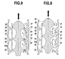
- each stage of the mixer comprises a body 32 and a movable core 33 and has at least two turbulence rings 31.
- the inner wall of the body 32 of the mixer is provided with at least two grooves 34 and two seats 35.
- the wall of the core comprises at least two flanges 36 in the form of movable flaps and at least two grooves 37 complementary to those of the body.
- the core 33 receives the thrust of a rod 33a ( Fig.6 and 7 ) whose axial position is adjustable, and is guided by fixed guides 33b.
- Each body groove assembly 34 / core groove 37 includes a valve 36 and a seat 35 reducing the passage section, followed by one (or more) turbulence ring 31 itself.
- the shapes of the grooves 34, 37, visible in the drawings, concavities facing, are provided to create a ring by a minimum pressure drop with a rapid rotation of the fluid in all positions of the core, creating less cavitation output of seat.
- the turbulence rings 31 are made to obtain in each ring a cycle of fluid velocity variation having an acceleration and a reduction as regular as possible.
- the entrance to the conical seat is effected in the direction of the arrows on Fig.8 and 9 , radially from the outside inwards to reach the turbulence ring.
- the body / core assemblies are connected in series, and their number is chosen so that the total pressure drop has the desired value.
- the mixer MEV may comprise an axial adjustment means 38 with screw 39 ( Fig.6 ) to allow manual adjustment of the core 33 relative to the body 32.
- the axial adjustment means 38 comprises a pneumatic cylinder 40 to enable the position of the core 33 relative to the body 32 to be automatically adjusted.
- the jack 40 is of the pull-down type, so as not to affect the sensitivity.
- the mixer When the mixer is multi-stage MEV, including three stages as illustrated on Fig.6 and 7 , it is provided with a common adjustment means 38 for adjusting the pressure losses of the downstream stage.
- Different cores in particular of different lengths, are provided for each stage so that the pressure drops of each stage are decreasing, from upstream to downstream, so as not to destabilize the product at the mixer outlet in the zone of weaker pressure.
- the cores of each stage are supported against each other, so that the axial displacement of the downstream core is transmitted to the upstream nuclei.
- the mixer MEV is disposed downstream of the pump PB and upstream of the loop output connection BS.
- the installation preferably comprises an output modulating valve (not shown) controlled by a regulation to regulate the outflow necessary to supply the printer, according to its level according to the power supply mode of the printer (see adaptation as an alternative ARV-E 4-way valve with modulating valve).
- an output modulating valve (not shown) controlled by a regulation to regulate the outflow necessary to supply the printer, according to its level according to the power supply mode of the printer (see adaptation as an alternative ARV-E 4-way valve with modulating valve).
- the control controls the flow rate of the injected gas, measured by the mass flowmeter DB2m, in proportion to the flow rate used, measured by a precision flowmeter 6 compatible to ensure a continuous accurate dosage of the gas.
- the installation may comprise one or more positive pumps (not shown) depending on the number of additives to be injected and one or more corresponding flow meters for proportional dosing at the useful rate.
- the dynamic loop 5 is located in a vertical plane.
- the PB pump is characterized by a high suction capacity and a high discharge pressure, in particular from 5 to 15 bar (possibility of multistage or volumetric pump).
- the saturator CAH is traversed horizontally by the liquids and ensures a first dissolution of the gas? in order to avoid any cavitation of the pump PB.
- the part of the loop 5 extending between the output of the pump PB and the branch BS of the feed line 4 of the printer constitutes a so-called chambering loop.
- This chambering loop has a capacity (dynamic capacity CDY) adapted to the flow and the product manufactured.
- the chambering loop in particular to facilitate the dosing of the product in the liquid, without reaching too high heights, it can increase the outer diameter of the CDY capacity.
- the greater capacity of the loop makes it possible to smooth the small variations of dosage during flow variations.
- the dynamic loop makes it possible to obtain a constant flow rate in the injection zone of the liquid and gaseous components, irrespective of the variations in the flow rate used between the zero flow rate and the nominal flow rate of the device.
- the specific accessories used make it possible to obtain a stable pressure at the various points of the dynamic loop independently of the outflow.
- the pressure scheme of the loop can be adjusted according to the desired products and results.
- the pressure variations in the loop have a strong influence on the stability of the product.
- the higher the pressure in the loop the more stable the saturation. The interest of obtaining stable pressures is therefore clear.
- the mixture of product products, led products (additives) and gas, constant in proportion, is delivered, according to the flow drawn by the printer, the dynamic loop in which it circulates continuously and at constant speed even in case of stoppage of the speed of the printer.
- the function of the dynamic loop 5 is to ensure a constant proportionality as well as a homogeneity of the mixture, despite the small variations due to stopping and restarting the flow resulting from the stops of the printer.
- the very low buffer capacity of the installation according to the invention allows cleaning and sterilization "online" of the installation. Product changes can be much faster.
- the lines (not shown) delivering the products to be mixed with the product leading into the dynamic loop may comprise a positive displacement pump (for example piston or gear example) controlled by a frequency converter, so that the setting is less sensitive to pressure variations.
- the installation is completed by manometers or pressure sensors Pab, Pap, Pr, Pr1, Ps provided at different points of the installation and the dynamic loop.
- the mixture is injected into the dynamic loop 5 via the feed pump 2.
- CO2 gas is injected via the flowmeter DB2m and the saturator CAH.
- the mixture via the pump PB, then arrives in the mixing nozzle 27 of the CDY dynamic capacity where an intense stirring improves its homogeneity.
- the MEV mixer perfect homogeneity while reducing pressure, with decreasing pressure drops from upstream to downstream to avoid destabilizing the gaseous liquid.
- a sample can then be taken to the printer through line 4.
- the untapped portion of the mixture is recirculated back into loop 5.
- the bottled mixture is homogeneous, the saturation of gas is stable, the gas is dissolved and perfectly bonded.
Landscapes
- Chemical & Material Sciences (AREA)
- Chemical Kinetics & Catalysis (AREA)
- Dispersion Chemistry (AREA)
- Accessories For Mixers (AREA)
- Gas Separation By Absorption (AREA)
Priority Applications (1)
| Application Number | Priority Date | Filing Date | Title |
|---|---|---|---|
| EP11194936A EP2433706A1 (de) | 2009-09-03 | 2010-08-10 | Sättiger zum Einspritzen eines Gases in eine Flüssigkeit |
Applications Claiming Priority (1)
| Application Number | Priority Date | Filing Date | Title |
|---|---|---|---|
| FR0904185A FR2949355B1 (fr) | 2009-09-03 | 2009-09-03 | Installation pour elaborer un melange homogene gazeux a partir de constituants liquides et gazeux |
Related Child Applications (1)
| Application Number | Title | Priority Date | Filing Date |
|---|---|---|---|
| EP11194936.8 Division-Into | 2011-12-21 |
Publications (2)
| Publication Number | Publication Date |
|---|---|
| EP2292321A1 true EP2292321A1 (de) | 2011-03-09 |
| EP2292321B1 EP2292321B1 (de) | 2012-02-08 |
Family
ID=42103043
Family Applications (2)
| Application Number | Title | Priority Date | Filing Date |
|---|---|---|---|
| EP11194936A Withdrawn EP2433706A1 (de) | 2009-09-03 | 2010-08-10 | Sättiger zum Einspritzen eines Gases in eine Flüssigkeit |
| EP10172361A Active EP2292321B1 (de) | 2009-09-03 | 2010-08-10 | Anlage zur Herstellung eines homogenen Gasgemischs aus flüssigen und gasförmigen Bestandteilen |
Family Applications Before (1)
| Application Number | Title | Priority Date | Filing Date |
|---|---|---|---|
| EP11194936A Withdrawn EP2433706A1 (de) | 2009-09-03 | 2010-08-10 | Sättiger zum Einspritzen eines Gases in eine Flüssigkeit |
Country Status (3)
| Country | Link |
|---|---|
| EP (2) | EP2433706A1 (de) |
| AT (1) | ATE544507T1 (de) |
| FR (1) | FR2949355B1 (de) |
Cited By (12)
| Publication number | Priority date | Publication date | Assignee | Title |
|---|---|---|---|---|
| CN102321148A (zh) * | 2011-08-16 | 2012-01-18 | 甘肃华羚酪蛋白股份有限公司 | 一种自动管道点酸装置 |
| CN102351945A (zh) * | 2011-08-16 | 2012-02-15 | 甘肃华羚酪蛋白股份有限公司 | 自动配酸装置和自动管道点酸装置及自动配酸点酸方法 |
| EP2656908A1 (de) | 2012-04-25 | 2013-10-30 | Umicore AG & Co. KG | Statischer Gasmischer |
| CN103429355A (zh) * | 2011-06-09 | 2013-12-04 | Abb株式会社 | 换色阀装置 |
| EP2703070A3 (de) * | 2012-08-31 | 2015-02-11 | Krones AG | Misch-Regelventil und Verfahren |
| CN106163651A (zh) * | 2014-03-20 | 2016-11-23 | Idec株式会社 | 细泡沫液产生装置 |
| CN110375816A (zh) * | 2019-07-25 | 2019-10-25 | 广东工业大学 | 一种文丘里管射流装置 |
| CN110773016A (zh) * | 2019-12-03 | 2020-02-11 | 新榕能源(福建)有限公司 | 一种全自动甲醇汽油连续调配系统 |
| CN113145007A (zh) * | 2021-05-26 | 2021-07-23 | 昆明珑瑞一焰气体产品配送服务有限公司 | 一种用于天然气与添加剂混合输送的装置 |
| US11208314B2 (en) | 2015-01-30 | 2021-12-28 | Anheuser-Busch Inbev S.A. | Pressurized beverage concentrates and appliances and methods for producing beverages therefrom |
| CN114486810A (zh) * | 2022-02-11 | 2022-05-13 | 迈射智能科技(上海)有限公司 | 一种基于多组分标气系统的油样混油系统及检测方法 |
| CN115090188A (zh) * | 2022-06-14 | 2022-09-23 | 桂林航天工业学院 | 一种陶瓷涂料用的微波搅拌机 |
Families Citing this family (8)
| Publication number | Priority date | Publication date | Assignee | Title |
|---|---|---|---|---|
| CN102606164B (zh) * | 2012-04-13 | 2014-02-19 | 大连华峰发展公司 | 一种盾构机泡沫注射系统及其工作方法 |
| FR2996781B1 (fr) | 2012-10-12 | 2020-01-10 | Sdel Alsace | Saturateur permettant l'injection d'un gaz dans un liquide |
| LU92380B1 (en) | 2014-02-19 | 2015-08-20 | Luxembourg Patent Co Sa | In-line carbonation of water-base beverages |
| CN105890677B (zh) * | 2016-04-28 | 2021-11-02 | 山东省计量科学研究院 | 一种小微气体流量发生器 |
| ES2767024B2 (es) | 2018-12-14 | 2021-09-17 | Univ Sevilla | Dispositivo generador de vortices en canales o conductos |
| RU195599U1 (ru) * | 2019-10-18 | 2020-01-31 | Федеральное государственное автономное образовательное учреждение высшего образования «Дальневосточный федеральный университет» (ДВФУ) | Сатуратор |
| CN112871005B (zh) * | 2021-01-18 | 2023-04-07 | 福州外语外贸学院 | 一种用于实验室的双缸循环型料液混合机 |
| CN119288543B (zh) * | 2024-09-20 | 2025-10-21 | 中国铁建重工集团股份有限公司 | Uhpc超高性能混凝土喷砌台车 |
Citations (5)
| Publication number | Priority date | Publication date | Assignee | Title |
|---|---|---|---|---|
| DE688790C (de) * | 1935-04-23 | 1940-03-01 | Albert Surber | Verfahren zum Impraegnieren unter Umwaelzung von in einem Behaelter befindlichen alkoholfreien natuerlichen Saeften mittels Kohlensaeure |
| FR2772367A1 (fr) | 1997-12-11 | 1999-06-18 | Georges Ollier | Perfectionnements apportes a la realisation de melanges notamment pour la fabrication de boissons gazeuses |
| DE102004013001A1 (de) * | 2004-03-16 | 2005-10-13 | Dsi Getränkearmaturen Gmbh | Anordnung zum Einbringen von Gas in eine Flüssigkeit |
| WO2007141339A1 (de) * | 2006-06-09 | 2007-12-13 | Balda Solutions Deutschland Gmbh | Verfahren und vorrichtung für die anreicherung eines flüssigkeitsstroms mit einem gas |
| EP1974802A1 (de) * | 2007-03-29 | 2008-10-01 | Electrolux Home Products Corporation N.V. | Kaltgetränkespender für den Hausgebrauch und damit ausgestatteter Kühlschrank |
Family Cites Families (3)
| Publication number | Priority date | Publication date | Assignee | Title |
|---|---|---|---|---|
| DE4426159A1 (de) * | 1994-07-22 | 1994-12-08 | Voith Gmbh J M | Flotationseinrichtung |
| US6422735B1 (en) * | 1999-09-20 | 2002-07-23 | John Stewart Lang | Hydraulic jet flash mixer with open injection port in the flow deflector |
| NO328780B1 (no) * | 2007-11-15 | 2010-05-10 | Yara Int Asa | Apparat og fremgangsmate for a dannelse av og fordeling av bobler i en gass/vaeske blanding |
-
2009
- 2009-09-03 FR FR0904185A patent/FR2949355B1/fr not_active Expired - Fee Related
-
2010
- 2010-08-10 AT AT10172361T patent/ATE544507T1/de active
- 2010-08-10 EP EP11194936A patent/EP2433706A1/de not_active Withdrawn
- 2010-08-10 EP EP10172361A patent/EP2292321B1/de active Active
Patent Citations (6)
| Publication number | Priority date | Publication date | Assignee | Title |
|---|---|---|---|---|
| DE688790C (de) * | 1935-04-23 | 1940-03-01 | Albert Surber | Verfahren zum Impraegnieren unter Umwaelzung von in einem Behaelter befindlichen alkoholfreien natuerlichen Saeften mittels Kohlensaeure |
| FR2772367A1 (fr) | 1997-12-11 | 1999-06-18 | Georges Ollier | Perfectionnements apportes a la realisation de melanges notamment pour la fabrication de boissons gazeuses |
| US6439437B1 (en) | 1997-12-11 | 2002-08-27 | Georges Ollier | Preparation of mixtures for the production of aerated beverages |
| DE102004013001A1 (de) * | 2004-03-16 | 2005-10-13 | Dsi Getränkearmaturen Gmbh | Anordnung zum Einbringen von Gas in eine Flüssigkeit |
| WO2007141339A1 (de) * | 2006-06-09 | 2007-12-13 | Balda Solutions Deutschland Gmbh | Verfahren und vorrichtung für die anreicherung eines flüssigkeitsstroms mit einem gas |
| EP1974802A1 (de) * | 2007-03-29 | 2008-10-01 | Electrolux Home Products Corporation N.V. | Kaltgetränkespender für den Hausgebrauch und damit ausgestatteter Kühlschrank |
Cited By (24)
| Publication number | Priority date | Publication date | Assignee | Title |
|---|---|---|---|---|
| CN103429355A (zh) * | 2011-06-09 | 2013-12-04 | Abb株式会社 | 换色阀装置 |
| CN103429355B (zh) * | 2011-06-09 | 2016-04-27 | Abb株式会社 | 换色阀装置 |
| CN102321148A (zh) * | 2011-08-16 | 2012-01-18 | 甘肃华羚酪蛋白股份有限公司 | 一种自动管道点酸装置 |
| CN102351945A (zh) * | 2011-08-16 | 2012-02-15 | 甘肃华羚酪蛋白股份有限公司 | 自动配酸装置和自动管道点酸装置及自动配酸点酸方法 |
| CN102321148B (zh) * | 2011-08-16 | 2013-08-07 | 甘肃华羚酪蛋白股份有限公司 | 一种自动管道点酸装置 |
| CN102351945B (zh) * | 2011-08-16 | 2013-11-20 | 甘肃华羚酪蛋白股份有限公司 | 自动配酸装置和自动管道点酸装置及自动配酸点酸方法 |
| EP2656908A1 (de) | 2012-04-25 | 2013-10-30 | Umicore AG & Co. KG | Statischer Gasmischer |
| DE102012008108A1 (de) | 2012-04-25 | 2013-10-31 | Umicore Ag & Co. Kg | Statischer Gasmischer |
| US9346026B2 (en) | 2012-04-25 | 2016-05-24 | Umicore Ag & Co. Kg | Static gas mixer |
| EP2703070A3 (de) * | 2012-08-31 | 2015-02-11 | Krones AG | Misch-Regelventil und Verfahren |
| US10315170B2 (en) | 2014-03-20 | 2019-06-11 | Idec Corporation | Fine bubble-containing liquid generating apparatus |
| CN106163651A (zh) * | 2014-03-20 | 2016-11-23 | Idec株式会社 | 细泡沫液产生装置 |
| CN106163651B (zh) * | 2014-03-20 | 2019-06-18 | Idec株式会社 | 细泡沫液产生装置 |
| EP3103547A4 (de) * | 2014-03-20 | 2017-03-29 | Idec Corporation | Vorrichtung zur erzeugung von feinblasiger flüssigkeit |
| US11208314B2 (en) | 2015-01-30 | 2021-12-28 | Anheuser-Busch Inbev S.A. | Pressurized beverage concentrates and appliances and methods for producing beverages therefrom |
| CN110375816A (zh) * | 2019-07-25 | 2019-10-25 | 广东工业大学 | 一种文丘里管射流装置 |
| CN110773016A (zh) * | 2019-12-03 | 2020-02-11 | 新榕能源(福建)有限公司 | 一种全自动甲醇汽油连续调配系统 |
| CN110773016B (zh) * | 2019-12-03 | 2023-09-22 | 新榕能源(福建)有限公司 | 一种全自动甲醇汽油连续调配系统 |
| CN113145007A (zh) * | 2021-05-26 | 2021-07-23 | 昆明珑瑞一焰气体产品配送服务有限公司 | 一种用于天然气与添加剂混合输送的装置 |
| CN113145007B (zh) * | 2021-05-26 | 2023-03-10 | 昆明珑瑞一焰气体产品配送服务有限公司 | 一种用于天然气与添加剂混合输送的装置 |
| CN114486810A (zh) * | 2022-02-11 | 2022-05-13 | 迈射智能科技(上海)有限公司 | 一种基于多组分标气系统的油样混油系统及检测方法 |
| CN114486810B (zh) * | 2022-02-11 | 2024-03-15 | 迈射智能科技(上海)有限公司 | 一种基于多组分标气系统的油样混油系统及检测方法 |
| CN115090188A (zh) * | 2022-06-14 | 2022-09-23 | 桂林航天工业学院 | 一种陶瓷涂料用的微波搅拌机 |
| CN115090188B (zh) * | 2022-06-14 | 2023-08-15 | 桂林航天工业学院 | 一种陶瓷涂料用的微波搅拌机 |
Also Published As
| Publication number | Publication date |
|---|---|
| ATE544507T1 (de) | 2012-02-15 |
| FR2949355B1 (fr) | 2011-09-09 |
| FR2949355A1 (fr) | 2011-03-04 |
| EP2433706A1 (de) | 2012-03-28 |
| EP2292321B1 (de) | 2012-02-08 |
Similar Documents
| Publication | Publication Date | Title |
|---|---|---|
| EP2292321B1 (de) | Anlage zur Herstellung eines homogenen Gasgemischs aus flüssigen und gasförmigen Bestandteilen | |
| JP6671093B2 (ja) | 乳製品、特にミルクフォームを製造する方法および装置 | |
| US5842600A (en) | Tankless beverage water carbonation process and apparatus | |
| US20180236417A1 (en) | Liquid inline mixing and gas infusion system | |
| EP0601329B1 (de) | Einrichtung und Verfahren zur Behandlung eines Fluidums durch Dampfinjektion | |
| US20200390127A1 (en) | Apparatuses, systems, and methods for inline injection of gases into liquids | |
| EP2891622B1 (de) | Vorrichtung zur Ausgabe eines Getränks, die das Einspritzen mindestens eines Zusatzstoffes in das ausgegebene Getränk ermöglicht | |
| CN101410170A (zh) | 浸渍机 | |
| US4173296A (en) | Apparatus for mixing and dispensing a beverage | |
| US6698473B2 (en) | Cone-shaped jet filling tube and filling machine equipped therewith | |
| AU2019278900A1 (en) | Apparatus in the form of a unitary, single-piece structure configured to generate and mix ultra-fine gas bubbles into a high gas concentration aqueous solution | |
| FR2495012A1 (fr) | Appareil pour melanger une solution de concentres en particulier d'eau et de polymeres liquides pour la recuperation assistee du petrole | |
| CA1218338A (en) | Method and an apparatus for the production and dispensing in portions of still mixed drinks from fruit syrup or concentrates and water | |
| FR3042127A1 (fr) | Bec d'injection pour composition cosmetique avec effet marbre, module et machine associes | |
| EP1773479B1 (de) | Dosiervorrichtung zum einführen eines additivs in einen flüssigkeitsstrom | |
| EP0179111B1 (de) | Tragwagen für fahrzeug oder material | |
| EP3579979B2 (de) | Sprühkopf für ein fluidprodukt und verwendung solch eines kopfes | |
| EP0179113A1 (de) | Vorrichtung zur ausgabe von flüssigkeiten wie flüssiger nahrung und insbesondere getränken. | |
| FR3104549A1 (fr) | Installation de conditionnement comprenant des becs de remplissage reliés à des canalisations de retour | |
| FR3104550A1 (fr) | Poste de remplissage pour installation de conditionnement comprenant un bec de remplissage à canal d’aspiration intégré | |
| EP1049530A1 (de) | Verbesserungen zur herstellung von mischungen,insbesondere zur herstellung gashaltiger getränke | |
| FR2968580A1 (fr) | Dispositif melangeur pour installation de douche et installation de douche equipee d'un tel dispositif melangeur | |
| CN115920687B (zh) | 一种润滑油输送装置及调和方法 | |
| WO2024172866A1 (en) | Inline carbonator | |
| FR2542622A1 (fr) | Doseur de produit moussant concentre pour un systeme d'extincteur |
Legal Events
| Date | Code | Title | Description |
|---|---|---|---|
| PUAI | Public reference made under article 153(3) epc to a published international application that has entered the european phase |
Free format text: ORIGINAL CODE: 0009012 |
|
| AK | Designated contracting states |
Kind code of ref document: A1 Designated state(s): AL AT BE BG CH CY CZ DE DK EE ES FI FR GB GR HR HU IE IS IT LI LT LU LV MC MK MT NL NO PL PT RO SE SI SK SM TR |
|
| AX | Request for extension of the european patent |
Extension state: BA ME RS |
|
| 17P | Request for examination filed |
Effective date: 20110622 |
|
| RIC1 | Information provided on ipc code assigned before grant |
Ipc: B01F 5/10 20060101ALI20110707BHEP Ipc: B01F 5/06 20060101ALI20110707BHEP Ipc: B01F 5/04 20060101ALI20110707BHEP Ipc: B01F 3/04 20060101AFI20110707BHEP |
|
| GRAP | Despatch of communication of intention to grant a patent |
Free format text: ORIGINAL CODE: EPIDOSNIGR1 |
|
| GRAS | Grant fee paid |
Free format text: ORIGINAL CODE: EPIDOSNIGR3 |
|
| GRAA | (expected) grant |
Free format text: ORIGINAL CODE: 0009210 |
|
| AK | Designated contracting states |
Kind code of ref document: B1 Designated state(s): AL AT BE BG CH CY CZ DE DK EE ES FI FR GB GR HR HU IE IS IT LI LT LU LV MC MK MT NL NO PL PT RO SE SI SK SM TR |
|
| AX | Request for extension of the european patent |
Extension state: BA ME RS |
|
| REG | Reference to a national code |
Ref country code: GB Ref legal event code: FG4D Free format text: NOT ENGLISH |
|
| REG | Reference to a national code |
Ref country code: AT Ref legal event code: REF Ref document number: 544507 Country of ref document: AT Kind code of ref document: T Effective date: 20120215 Ref country code: CH Ref legal event code: EP |
|
| REG | Reference to a national code |
Ref country code: DE Ref legal event code: R096 Ref document number: 602010000820 Country of ref document: DE Effective date: 20120412 |
|
| REG | Reference to a national code |
Ref country code: NL Ref legal event code: T3 |
|
| REG | Reference to a national code |
Ref country code: SE Ref legal event code: TRGR |
|
| LTIE | Lt: invalidation of european patent or patent extension |
Effective date: 20120208 |
|
| PG25 | Lapsed in a contracting state [announced via postgrant information from national office to epo] |
Ref country code: HR Free format text: LAPSE BECAUSE OF FAILURE TO SUBMIT A TRANSLATION OF THE DESCRIPTION OR TO PAY THE FEE WITHIN THE PRESCRIBED TIME-LIMIT Effective date: 20120208 Ref country code: IS Free format text: LAPSE BECAUSE OF FAILURE TO SUBMIT A TRANSLATION OF THE DESCRIPTION OR TO PAY THE FEE WITHIN THE PRESCRIBED TIME-LIMIT Effective date: 20120608 Ref country code: LT Free format text: LAPSE BECAUSE OF FAILURE TO SUBMIT A TRANSLATION OF THE DESCRIPTION OR TO PAY THE FEE WITHIN THE PRESCRIBED TIME-LIMIT Effective date: 20120208 Ref country code: NO Free format text: LAPSE BECAUSE OF FAILURE TO SUBMIT A TRANSLATION OF THE DESCRIPTION OR TO PAY THE FEE WITHIN THE PRESCRIBED TIME-LIMIT Effective date: 20120508 |
|
| REG | Reference to a national code |
Ref country code: IE Ref legal event code: FD4D |
|
| PG25 | Lapsed in a contracting state [announced via postgrant information from national office to epo] |
Ref country code: LV Free format text: LAPSE BECAUSE OF FAILURE TO SUBMIT A TRANSLATION OF THE DESCRIPTION OR TO PAY THE FEE WITHIN THE PRESCRIBED TIME-LIMIT Effective date: 20120208 Ref country code: PT Free format text: LAPSE BECAUSE OF FAILURE TO SUBMIT A TRANSLATION OF THE DESCRIPTION OR TO PAY THE FEE WITHIN THE PRESCRIBED TIME-LIMIT Effective date: 20120608 Ref country code: PL Free format text: LAPSE BECAUSE OF FAILURE TO SUBMIT A TRANSLATION OF THE DESCRIPTION OR TO PAY THE FEE WITHIN THE PRESCRIBED TIME-LIMIT Effective date: 20120208 Ref country code: FI Free format text: LAPSE BECAUSE OF FAILURE TO SUBMIT A TRANSLATION OF THE DESCRIPTION OR TO PAY THE FEE WITHIN THE PRESCRIBED TIME-LIMIT Effective date: 20120208 Ref country code: GR Free format text: LAPSE BECAUSE OF FAILURE TO SUBMIT A TRANSLATION OF THE DESCRIPTION OR TO PAY THE FEE WITHIN THE PRESCRIBED TIME-LIMIT Effective date: 20120509 |
|
| REG | Reference to a national code |
Ref country code: AT Ref legal event code: MK05 Ref document number: 544507 Country of ref document: AT Kind code of ref document: T Effective date: 20120208 |
|
| PG25 | Lapsed in a contracting state [announced via postgrant information from national office to epo] |
Ref country code: CY Free format text: LAPSE BECAUSE OF FAILURE TO SUBMIT A TRANSLATION OF THE DESCRIPTION OR TO PAY THE FEE WITHIN THE PRESCRIBED TIME-LIMIT Effective date: 20120208 |
|
| PG25 | Lapsed in a contracting state [announced via postgrant information from national office to epo] |
Ref country code: RO Free format text: LAPSE BECAUSE OF FAILURE TO SUBMIT A TRANSLATION OF THE DESCRIPTION OR TO PAY THE FEE WITHIN THE PRESCRIBED TIME-LIMIT Effective date: 20120208 Ref country code: SI Free format text: LAPSE BECAUSE OF FAILURE TO SUBMIT A TRANSLATION OF THE DESCRIPTION OR TO PAY THE FEE WITHIN THE PRESCRIBED TIME-LIMIT Effective date: 20120208 Ref country code: EE Free format text: LAPSE BECAUSE OF FAILURE TO SUBMIT A TRANSLATION OF THE DESCRIPTION OR TO PAY THE FEE WITHIN THE PRESCRIBED TIME-LIMIT Effective date: 20120208 Ref country code: DK Free format text: LAPSE BECAUSE OF FAILURE TO SUBMIT A TRANSLATION OF THE DESCRIPTION OR TO PAY THE FEE WITHIN THE PRESCRIBED TIME-LIMIT Effective date: 20120208 Ref country code: IE Free format text: LAPSE BECAUSE OF FAILURE TO SUBMIT A TRANSLATION OF THE DESCRIPTION OR TO PAY THE FEE WITHIN THE PRESCRIBED TIME-LIMIT Effective date: 20120208 Ref country code: CZ Free format text: LAPSE BECAUSE OF FAILURE TO SUBMIT A TRANSLATION OF THE DESCRIPTION OR TO PAY THE FEE WITHIN THE PRESCRIBED TIME-LIMIT Effective date: 20120208 |
|
| PG25 | Lapsed in a contracting state [announced via postgrant information from national office to epo] |
Ref country code: SK Free format text: LAPSE BECAUSE OF FAILURE TO SUBMIT A TRANSLATION OF THE DESCRIPTION OR TO PAY THE FEE WITHIN THE PRESCRIBED TIME-LIMIT Effective date: 20120208 |
|
| PLBE | No opposition filed within time limit |
Free format text: ORIGINAL CODE: 0009261 |
|
| STAA | Information on the status of an ep patent application or granted ep patent |
Free format text: STATUS: NO OPPOSITION FILED WITHIN TIME LIMIT |
|
| 26N | No opposition filed |
Effective date: 20121109 |
|
| PG25 | Lapsed in a contracting state [announced via postgrant information from national office to epo] |
Ref country code: AT Free format text: LAPSE BECAUSE OF FAILURE TO SUBMIT A TRANSLATION OF THE DESCRIPTION OR TO PAY THE FEE WITHIN THE PRESCRIBED TIME-LIMIT Effective date: 20120208 |
|
| REG | Reference to a national code |
Ref country code: DE Ref legal event code: R097 Ref document number: 602010000820 Country of ref document: DE Effective date: 20121109 |
|
| PG25 | Lapsed in a contracting state [announced via postgrant information from national office to epo] |
Ref country code: MC Free format text: LAPSE BECAUSE OF NON-PAYMENT OF DUE FEES Effective date: 20120831 |
|
| PG25 | Lapsed in a contracting state [announced via postgrant information from national office to epo] |
Ref country code: ES Free format text: LAPSE BECAUSE OF FAILURE TO SUBMIT A TRANSLATION OF THE DESCRIPTION OR TO PAY THE FEE WITHIN THE PRESCRIBED TIME-LIMIT Effective date: 20120519 |
|
| PG25 | Lapsed in a contracting state [announced via postgrant information from national office to epo] |
Ref country code: BG Free format text: LAPSE BECAUSE OF FAILURE TO SUBMIT A TRANSLATION OF THE DESCRIPTION OR TO PAY THE FEE WITHIN THE PRESCRIBED TIME-LIMIT Effective date: 20120508 |
|
| PG25 | Lapsed in a contracting state [announced via postgrant information from national office to epo] |
Ref country code: AL Free format text: LAPSE BECAUSE OF FAILURE TO SUBMIT A TRANSLATION OF THE DESCRIPTION OR TO PAY THE FEE WITHIN THE PRESCRIBED TIME-LIMIT Effective date: 20120208 Ref country code: MT Free format text: LAPSE BECAUSE OF FAILURE TO SUBMIT A TRANSLATION OF THE DESCRIPTION OR TO PAY THE FEE WITHIN THE PRESCRIBED TIME-LIMIT Effective date: 20120208 |
|
| PG25 | Lapsed in a contracting state [announced via postgrant information from national office to epo] |
Ref country code: TR Free format text: LAPSE BECAUSE OF FAILURE TO SUBMIT A TRANSLATION OF THE DESCRIPTION OR TO PAY THE FEE WITHIN THE PRESCRIBED TIME-LIMIT Effective date: 20120208 |
|
| PG25 | Lapsed in a contracting state [announced via postgrant information from national office to epo] |
Ref country code: SM Free format text: LAPSE BECAUSE OF FAILURE TO SUBMIT A TRANSLATION OF THE DESCRIPTION OR TO PAY THE FEE WITHIN THE PRESCRIBED TIME-LIMIT Effective date: 20120208 Ref country code: LU Free format text: LAPSE BECAUSE OF NON-PAYMENT OF DUE FEES Effective date: 20120810 |
|
| PG25 | Lapsed in a contracting state [announced via postgrant information from national office to epo] |
Ref country code: HU Free format text: LAPSE BECAUSE OF FAILURE TO SUBMIT A TRANSLATION OF THE DESCRIPTION OR TO PAY THE FEE WITHIN THE PRESCRIBED TIME-LIMIT Effective date: 20100810 |
|
| GBPC | Gb: european patent ceased through non-payment of renewal fee |
Effective date: 20140810 |
|
| REG | Reference to a national code |
Ref country code: DE Ref legal event code: R082 Ref document number: 602010000820 Country of ref document: DE Representative=s name: PATENTANWAELTE UND RECHTSANWALT WEISS, ARAT & , DE Ref country code: DE Ref legal event code: R082 Ref document number: 602010000820 Country of ref document: DE Representative=s name: PATENTANWAELTE UND RECHTSANWALT DR. WEISS, ARA, DE |
|
| PG25 | Lapsed in a contracting state [announced via postgrant information from national office to epo] |
Ref country code: GB Free format text: LAPSE BECAUSE OF NON-PAYMENT OF DUE FEES Effective date: 20140810 Ref country code: MK Free format text: LAPSE BECAUSE OF FAILURE TO SUBMIT A TRANSLATION OF THE DESCRIPTION OR TO PAY THE FEE WITHIN THE PRESCRIBED TIME-LIMIT Effective date: 20120208 |
|
| REG | Reference to a national code |
Ref country code: FR Ref legal event code: PLFP Year of fee payment: 7 |
|
| REG | Reference to a national code |
Ref country code: FR Ref legal event code: PLFP Year of fee payment: 8 |
|
| REG | Reference to a national code |
Ref country code: FR Ref legal event code: PLFP Year of fee payment: 9 |
|
| REG | Reference to a national code |
Ref country code: DE Ref legal event code: R079 Ref document number: 602010000820 Country of ref document: DE Free format text: PREVIOUS MAIN CLASS: B01F0003040000 Ipc: B01F0023200000 |
|
| PGFP | Annual fee paid to national office [announced via postgrant information from national office to epo] |
Ref country code: NL Payment date: 20250724 Year of fee payment: 16 |
|
| PGFP | Annual fee paid to national office [announced via postgrant information from national office to epo] |
Ref country code: DE Payment date: 20250812 Year of fee payment: 16 |
|
| PGFP | Annual fee paid to national office [announced via postgrant information from national office to epo] |
Ref country code: IT Payment date: 20250808 Year of fee payment: 16 |
|
| PGFP | Annual fee paid to national office [announced via postgrant information from national office to epo] |
Ref country code: BE Payment date: 20250826 Year of fee payment: 16 |
|
| PGFP | Annual fee paid to national office [announced via postgrant information from national office to epo] |
Ref country code: FR Payment date: 20250716 Year of fee payment: 16 |
|
| PGFP | Annual fee paid to national office [announced via postgrant information from national office to epo] |
Ref country code: CH Payment date: 20250901 Year of fee payment: 16 Ref country code: SE Payment date: 20250826 Year of fee payment: 16 |