EP2292366B1 - Torche plasma à tête démontable avec bague à filetage trapézoïdal isocèle - Google Patents
Torche plasma à tête démontable avec bague à filetage trapézoïdal isocèle Download PDFInfo
- Publication number
- EP2292366B1 EP2292366B1 EP10170567.1A EP10170567A EP2292366B1 EP 2292366 B1 EP2292366 B1 EP 2292366B1 EP 10170567 A EP10170567 A EP 10170567A EP 2292366 B1 EP2292366 B1 EP 2292366B1
- Authority
- EP
- European Patent Office
- Prior art keywords
- thread
- torch
- assembly according
- ring
- head
- Prior art date
- Legal status (The legal status is an assumption and is not a legal conclusion. Google has not performed a legal analysis and makes no representation as to the accuracy of the status listed.)
- Active
Links
- 238000005520 cutting process Methods 0.000 claims description 12
- 229910001369 Brass Inorganic materials 0.000 claims description 10
- PXHVJJICTQNCMI-UHFFFAOYSA-N Nickel Chemical compound [Ni] PXHVJJICTQNCMI-UHFFFAOYSA-N 0.000 claims description 10
- 239000010951 brass Substances 0.000 claims description 10
- 238000011144 upstream manufacturing Methods 0.000 claims description 6
- 239000012530 fluid Substances 0.000 claims description 5
- 229910052759 nickel Inorganic materials 0.000 claims description 5
- 239000010935 stainless steel Substances 0.000 claims description 5
- 229910001220 stainless steel Inorganic materials 0.000 claims description 5
- RYGMFSIKBFXOCR-UHFFFAOYSA-N Copper Chemical compound [Cu] RYGMFSIKBFXOCR-UHFFFAOYSA-N 0.000 claims description 4
- 239000011248 coating agent Substances 0.000 claims description 3
- 238000000576 coating method Methods 0.000 claims description 3
- 229910052802 copper Inorganic materials 0.000 claims description 3
- 239000010949 copper Substances 0.000 claims description 3
- 238000003780 insertion Methods 0.000 claims description 3
- 230000037431 insertion Effects 0.000 claims description 3
- 230000000295 complement effect Effects 0.000 claims description 2
- 238000000034 method Methods 0.000 claims 1
- 235000010599 Verbascum thapsus Nutrition 0.000 description 61
- 244000178289 Verbascum thapsus Species 0.000 description 5
- 230000000694 effects Effects 0.000 description 4
- 238000005299 abrasion Methods 0.000 description 3
- 239000002184 metal Substances 0.000 description 3
- 229910052751 metal Inorganic materials 0.000 description 3
- 208000031968 Cadaver Diseases 0.000 description 2
- 230000007797 corrosion Effects 0.000 description 2
- 238000005260 corrosion Methods 0.000 description 2
- 239000000428 dust Substances 0.000 description 2
- 239000000463 material Substances 0.000 description 2
- 230000001681 protective effect Effects 0.000 description 2
- 238000007789 sealing Methods 0.000 description 2
- 206010010904 Convulsion Diseases 0.000 description 1
- 239000002826 coolant Substances 0.000 description 1
- 238000001816 cooling Methods 0.000 description 1
- 239000000110 cooling liquid Substances 0.000 description 1
- 230000008878 coupling Effects 0.000 description 1
- 238000010168 coupling process Methods 0.000 description 1
- 238000005859 coupling reaction Methods 0.000 description 1
- 230000006866 deterioration Effects 0.000 description 1
- 238000009826 distribution Methods 0.000 description 1
- 239000012777 electrically insulating material Substances 0.000 description 1
- 238000000605 extraction Methods 0.000 description 1
- 230000002427 irreversible effect Effects 0.000 description 1
- 230000007774 longterm Effects 0.000 description 1
- 238000004519 manufacturing process Methods 0.000 description 1
- 229910001092 metal group alloy Inorganic materials 0.000 description 1
- 230000002093 peripheral effect Effects 0.000 description 1
- 230000008646 thermal stress Effects 0.000 description 1
- 230000009466 transformation Effects 0.000 description 1
- 238000003466 welding Methods 0.000 description 1
Images
Classifications
-
- H—ELECTRICITY
- H05—ELECTRIC TECHNIQUES NOT OTHERWISE PROVIDED FOR
- H05H—PLASMA TECHNIQUE; PRODUCTION OF ACCELERATED ELECTRICALLY-CHARGED PARTICLES OR OF NEUTRONS; PRODUCTION OR ACCELERATION OF NEUTRAL MOLECULAR OR ATOMIC BEAMS
- H05H1/00—Generating plasma; Handling plasma
- H05H1/24—Generating plasma
- H05H1/26—Plasma torches
- H05H1/32—Plasma torches using an arc
- H05H1/34—Details, e.g. electrodes, nozzles
- H05H1/3423—Connecting means, e.g. electrical connecting means or fluid connections
-
- B—PERFORMING OPERATIONS; TRANSPORTING
- B23—MACHINE TOOLS; METAL-WORKING NOT OTHERWISE PROVIDED FOR
- B23K—SOLDERING OR UNSOLDERING; WELDING; CLADDING OR PLATING BY SOLDERING OR WELDING; CUTTING BY APPLYING HEAT LOCALLY, e.g. FLAME CUTTING; WORKING BY LASER BEAM
- B23K10/00—Welding or cutting by means of a plasma
-
- B—PERFORMING OPERATIONS; TRANSPORTING
- B23—MACHINE TOOLS; METAL-WORKING NOT OTHERWISE PROVIDED FOR
- B23K—SOLDERING OR UNSOLDERING; WELDING; CLADDING OR PLATING BY SOLDERING OR WELDING; CUTTING BY APPLYING HEAT LOCALLY, e.g. FLAME CUTTING; WORKING BY LASER BEAM
- B23K9/00—Arc welding or cutting
- B23K9/24—Features related to electrodes
- B23K9/28—Supporting devices for electrodes
- B23K9/29—Supporting devices adapted for making use of shielding means
- B23K9/291—Supporting devices adapted for making use of shielding means the shielding means being a gas
- B23K9/296—Supporting devices adapted for making use of shielding means the shielding means being a gas using non-consumable electrodes
Definitions
- the invention relates to a plasma torch with removable head, the assembly and rapid disassembly of which on the base or torch body is effected by means of a ring with isosceles trapezoidal thread.
- Plasma cutting torches with removable head have two main parts which can be assembled or disassembled from each other, namely a base or torch body which is usually fixed on a structure, such as a supporting frame provided with a mobile beam for example, and a nose or torch head which is removable.
- plasma cutting torches with removable head are known in particular from the documents EP-A-599709 , GB-A-2091594 , EP-A-801882 and EP-A-941018 .
- the base or torch body is an interface between the electric generator, the high frequency and / or high voltage box necessary for striking the arc, the gas regulation box and the cooling system.
- the pipes and electrical wires coming from the different elements converge on the base which groups together the different inlets and outlets of fluids, namely coolant, plasma gas and protective gas, as well as the electrical connections for the cathode and the ignition and pilot circuits.
- the nose or head of the torch contains the consumables of the torch, namely an electrode, an upstream gas diffuser, an upstream nozzle, a downstream gas diffuser and a downstream nozzle, as well as the internal gas and distribution circuits. cooling liquid.
- the other torch head which has just been detached from the torch body, that is to say from the base , can be dismantled, used consumables can be removed and replaced with new consumables.
- the head will therefore be ready to be reassembled when the lifetime limit for the consumables of the other head is reached.
- the assembly / disassembly of a torch head on a torch body is done by means of a ring, generally threaded, which allows to fix the torch head to the base which has an additional thread, and the tightening of which ensures the tightness of the fittings of the fluid conduits and the good contact between the electrical fittings.
- this ring is made of electrically insulating material.
- the problem that arises is therefore being able to manually mount and dismount the plasma torch head from the torch body without encountering the above-mentioned problems, in particular by minimizing the deterioration of the thread by abrasion, during each screwing or unscrewing operation, so as to preserve sealing and contact between the torch head and the torch body.
- the solution of the invention is an assembly formed by a plasma cutting torch head secured to a plasma torch body using a ring according to claim 1.
- the invention also relates to a plasma jet cutting process, in which a torch head according to the invention is used.
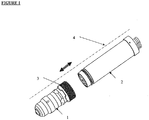
- the figure 1 represents a plasma cutting torch with a removable head 1 shown in the disassembled position on a body 2 of the torch, also called base.
- the head 1 conventionally comprises at its downstream end, an electrode, a nozzle and a protective cap.
- the fixing of the head 1 to the torch body 2 is conventionally done by screwing thanks to a threaded metal ring 3, coming to cooperate with a thread arranged on the torch body 2.
- the ring 3 is typically made of brass, preferably externally covered with a layer of nickel.
- the ring 3 is free and mobile in rotation around the external peripheral wall of the torch head 1, that is to say around the main axis 4 of the torch, and also in translation along the axis 4 of torch head 1.
- the torch When in use, the torch is subjected to often corrosive and / or dusty atmospheres, metallic dust in particular, in welding workshops or on an industrial site for example.
- the thread or thread present on the torch head 1 and / or on the base 2 can seize up and be abraded during successive assembly / disassembly of the head 1, which, in the long term, can lead to bad mounting the torch head 1 on its base 2 no longer ensuring good sealing of the fluid connections.
- complementary threads of particular thread section namely of isosceles trapezoidal thread section, and not of triangular shape, are provided on the torch head 1 and on the torch body 2 as conventionally used.
- the thread carried by the ring 3 is arranged on the internal wall of said ring 3, which is formed of brass. Furthermore, the thread carried by the body is arranged on its external wall which is formed of stainless steel.
- the thread of the ring 3 thread is made of brass, while the thread of the body thread is made of stainless steel.
- Such an isosceles trapezoidal section thread according to the invention is shown on the figure 2 .
- This type of thread is more robust than standard triangular section threads.
- the thickness of the threads is such that the thread is more resistant to abrasion and corrosion.
- such a thread allows a slight radial clearance relative to the axis of the torch which facilitates the insertion of the fluid and electrical connections, on the most upstream part of the torch head, in the corresponding housings located on the most downstream part of the base.
- this type of thread is an irreversible system: once screwed to the clamping point it will not unscrew under the simple effect of vibrations, like those existing on an automatic plasma cutting table, or even under the effect relaxation of mechanical and / or thermal stresses. Only the application of a torque on the ring, by an operator or an automatic mounting system, allows unscrewing.
- trapezoidal geometry is better suited for the transformation of a rotational movement, namely screwing and unscrewing of the ring 3 on the base 2, in translational movement, during the insertion or extraction of the head 1 of the base 2 torch.
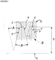
- the figure 2 details a thread of the ring 3 in accordance with the present invention.
- the thread of said thread 5 is of isosceles trapezoidal section, that is to say that the section of each thread has two lateral sides 7 forming between them an angle A of between 20 and 40 °, preferably between 25 and 35 °, more preferably of the order of 29 °, a large base and a small base, the small base being formed by the upper surface 6 of each net.
- the trapezoid is isosceles, therefore has two equal lateral sides 7.
- the thread 5 of the ring 3 comprises between 2 and 7 threads per inch (or 2.54 cm) considered in the direction of the length, that is to say along the axis 4 of the head 1, advantageously between 3 and 6 threads per inch.
- the distance D between the surface 6 of the thread 5 forming the small base of the trapezoid and the axis 4 of the torch head is between 50 and 70 mm, preferably of the order of 60.2 mm.
- the ring 3 is made of metal or a metal alloy, in particular brass covered with a nickel coating making it possible to limit the effect of corrosion.
- the corresponding thread on the body 2 is of the ACME type with a diameter of 60 mm and 6 threads / inch.
- an isosceles trapezoidal section or profile thread according to the invention also makes it possible to obtain better sliding of the threads one on the other, both when tightening and loosening, while retaining good jamming effect.
- the particular shape of the thread according to the invention is, on the one hand, easy to manufacture and, on the other hand, allows great precision in coupling and centering thanks to the efficient guidance provided by the sides of the threads.
Landscapes
- Engineering & Computer Science (AREA)
- Physics & Mathematics (AREA)
- Plasma & Fusion (AREA)
- Spectroscopy & Molecular Physics (AREA)
- Mechanical Engineering (AREA)
- Arc Welding In General (AREA)
- Plasma Technology (AREA)
Description
- L'invention concerne une torche à plasma à tête démontable dont le montage et le démontage rapide sur l'embase ou corps de torche se fait au moyen d'une bague à filetage trapézoïdal isocèle.
- Les torches de coupage plasma à tête démontable comportent deux parties principales pouvant être assemblées ou désassemblées l'une de l'autre, à savoir une embase ou corps de torche qui est habituellement fixé sur une structure, tel un bâti-porteur muni d'une poutre mobile par exemple, et un nez ou tête de torche qui est amovible.
- Des exemples de torches de coupage plasma à tête démontable sont notamment connus des documents
EP-A-599709 GB-A-2091594 EP-A-801882 EP-A-941018 - L'embase ou corps de torche est une interface entre le générateur électrique, le boîtier haute fréquence et/ou haute tension nécessaire à l'amorçage de l'arc, le boîtier de régulation des gaz et le système de refroidissement.
- De ce fait, les tuyaux et fils électriques issus des différents éléments convergent vers l'embase qui regroupe les différentes entrées et sorties de fluides, à savoir liquide de refroidissement, gaz plasmagène et gaz protecteur, ainsi que les connections électriques pour la cathode et les circuits d'amorçage et pilote.
- Le nez ou tête de la torche contient les consommables de la torche, à savoir une électrode, un diffuseur amont de gaz, une tuyère amont, un diffuseur aval de gaz et une tuyère aval, ainsi que les circuits internes de distribution des gaz et du liquide de refroidissement.
- Ces différents consommables s'érodent plus ou moins rapidement, lors de l'utilisation de la torche, et il est nécessaire de les remplacer par des consommables neufs après, en général, quelques heures d'utilisation, par exemple après 2 heures ou plus de coupage.
- Or, pouvoir séparer la tête de torche du corps de torche, c'est-à-dire de l'embase, est très pratique d'un point de vue de la productivité par rapport aux torches à tête non démontable car cela permet de préparer à l'avance une tête de torche comprenant des consommables neufs et de la raccorder au corps de torche immédiatement après démontage de la tête dont les consommables sont usés. Ceci se fait donc sans perte de temps et donc quasiment sans perte de productivité.
- Ensuite, pendant que la tête de torche nouvellement montée sur le corps est utilisée pour réaliser une opération de découpe, l'autre tête de torche qui vient d'être désolidarisée du corps de torche, c'est-à-dire de l'embase, peut être démontée, les consommables usés peuvent en être extraits et remplacés par des consommables neufs. La tête sera donc prête à être remontée lorsque la limite de durée de vie des consommables de l'autre tête sera atteinte.
- Le montage/démontage d'une tête de torche sur un corps de torche se fait au moyen d'une bague, en général filetée, qui permet de fixer la tête de torche à l'embase qui comporte un filetage complémentaire, et dont le serrage assure l'étanchéité des raccords des conduits de fluides et le bon contact entre les raccords électriques. Habituellement, cette bague est fabriquée en matériau électriquement isolant.
- Or, lors d'une utilisation intensive en milieu industriel, des poussières, notamment métalliques, détériorent progressivement le filetage par abrasion, lors de chaque opération de vissage ou dévissage.
- Il s'ensuit qu'au fil du temps, la tête de torche se monte de plus en plus difficilement sur le corps de torche et, par ailleurs, l'étanchéité et le contact entre la tête de la torche et le corps de torche ou embase ne sont plus assurés correctement.
- En outre, des problèmes se posent aussi lorsque la bague de serrage servant à connecter la tête de torche à l'embase est réalisée en un matériau différent de celui de l'embase. Ainsi, on a pu remarquer que des grippages se produisent lorsque l'embase est en acier inoxydable et la bague de serrage en cuivre ou laiton.
- Enfin, le montage de la tête de torche sur l'embase doit pouvoir être opéré facilement par l'opérateur et avec une grande précision.
- Le problème qui se pose est dès lors de pouvoir monter et démonter manuellement la tête de torche à plasma du corps de torche sans rencontrer les problèmes susmentionnés, en particulier en minimisant la détérioration du filetage par abrasion, lors de chaque opération de vissage ou dévissage, de manière à préserver étanchéité et contact entre la tête de la torche et le corps de torche.
- La solution de l'invention est un ensemble formé d'une tête de torche de coupage plasma solidarisée à un corps de torche plasma à l'aide d'une bague selon la revendication 1.
- Selon le cas, l'ensemble de l'invention peut comprendre l'une ou plusieurs des caractéristiques suivantes :
- la bague de serrage comporte au moins un filetage en cuivre ou laiton.
- le corps de torche porte un filetage formé d'acier inoxydable.
- le filetage comporte entre 2 et 7 filets par 2,54 cm (1 pouce).
- le filetage comporte entre 3 et 6 filets par 2,54 cm (1 pouce), de préférence 4 ou 5 filets par pouce.
- les deux côtés de chaque filet de section trapézoïdale forment entre eux un angle A compris entre 20 et 40°.
- les deux côtés de chaque filet de section trapézoïdale isocèle forment entre eux un angle A compris entre 25 et 35°, de préférence de l'ordre de 29°.
- la distance D entre la surface du filet formant la petite base du trapèze et l'axe de la tête de torche est comprise entre 50 et 70 mm, de préférence de l'ordre de 60,2 mm.
- la bague est formée de laiton recouvert extérieurement d'un revêtement en nickel.
- Par ailleurs, l'invention concerne également un procédé de coupage par jet de plasma, dans lequel on met en œuvre une tête de torche selon l'invention.
- La présente invention va être expliquée plus en détail en références aux figures annexées parmi lesquelles :
- la
figure 1 schématise une torche de coupage plasma à tête démontable vue en position désassemblée sur un corps de torche, et - la
figure 2 illustre le principe d'un filetage selon la présente invention destiné à une torche selon lafigure 1 . - La
figure 1 représente une torche de coupage plasma à tête 1 démontable montrée en position désassemblée sur un corps 2 de torche, encore appelé embase. La tête 1 comporte de manière classique à son extrémité aval, une électrode, une tuyère et une coiffe de protection. - La fixation de la tête 1 au corps 2 de torche se fait classiquement par vissage grâce à une bague 3 métallique taraudée, venant coopérer avec un filetage aménagé sur le corps 2 de torche.
- La bague 3 est typiquement en laiton, préférentiellement recouvert extérieurement d'une couche de nickel.
- La bague 3 est libre et mobile en rotation autour de la paroi périphérique externe de la tête 1 de torche, c'est-à-dire autour de l'axe 4 principal de la torche, et aussi en translation le long de l'axe 4 de la tête de torche 1.
- Lors de son utilisation, la torche est soumise à des atmosphères souvent corrosives et/ou poussiéreuses, poussières métallique en particulier, dans les ateliers de soudage ou sur site industriel par exemple. Dans de tels environnements, le pas de vis ou filetage présent sur la tête de torche 1 et/ou sur l'embase 2 peut se gripper et être abrasé lors des montages/démontages successifs de la tête 1, ce qui, à terme, peut conduire à un mauvais montage de la tête 1 de torche sur son embase 2 n'assurant plus une bonne étanchéité des raccords fluide.
- Afin d'éviter ce problème, selon la présente invention, on aménage sur la tête de torche 1 et sur le corps de torche 2 des filetages complémentaires de section de filet particulière, à savoir de section de filet trapézoïdale isocèle, et non de forme triangulaire comme classiquement utilisé.
- Le filetage porté par la bague 3 est aménagé sur la paroi interne de ladite bague 3, laquelle est formée de laiton. Par ailleurs, le filetage porté par le corps est aménagé sur sa paroi externe qui est formée d'acier inoxydable.
- Dit autrement, le filet du filetage de la bague 3 est en laiton, alors que le filet du filetage du corps est en acier inoxydable.
- Le fait d'utiliser des filetages de forme trapézoïdale isocèle, alors que les filetages de la bague et du corps sont réalisés dans des matériaux différents permet d'éviter ou minimiser les problèmes de grippage.
- Un tel filetage de section trapézoïdale isocèle selon l'invention est montré sur la
figure 2 . Ce type de filetage est plus robuste que les filetages standards de section triangulaires. L'épaisseur des filets est telle que le filetage est plus résistant à l'abrasion et la corrosion. - Par ailleurs, un tel filetage permet un léger jeu radial par rapport à l'axe de la torche se qui facilite l'insertion des raccords fluides et électriques, sur la partie la plus amont de la tête de torche, dans les logements correspondants situés sur la partie la plus aval de l'embase.
- De plus, ce type de filetage est un système irréversible : une fois vissé jusqu'au point de serrage il ne se dévissera pas sous le simple effet de vibrations, comme celles existant sur une table de découpe plasma automatique, ou encore sous l'effet du relâchement de contraintes mécaniques et/ou thermiques. Seule l'application d'un couple sur la bague, par un opérateur ou un système de montage automatique, permet le dévissage.
- Enfin, cette géométrie trapézoïdale isocèle est mieux adaptée pour la transformation d'un mouvement de rotation, à savoir vissage dévissage de la bague 3 sur l'embase 2, en mouvement de translation, lors de l'insertion ou de l'extraction de la tête 1 de la torche de l'embase 2.
- La
figure 2 détaille un filetage de la bague 3 conforme à la présente invention. Comme on peut le voir, le filet dudit filetage 5 est de section trapézoïdale isocèle, c'est-à-dire que la section de chaque filet comporte deux côtés latéraux 7 formant entre eux un angle A compris entre 20 et 40°, de préférence entre 25 et 35°, de préférence encore de l'ordre de 29°, une grande base et une petite base, la petite base étant formée par la surface supérieure 6 de chaque filet. Le trapèze est isocèle, donc comporte deux côtés latéraux 7 égaux. - Selon l'invention, le filetage 5 de la bague 3 comporte entre 2 et 7 filets par pouce (soit 2,54 cm) considéré dans le sens de la longueur, c'est-à-dire selon l'axe 4 de la tête 1, avantageusement entre 3 et 6 filets par pouce.
- Par ailleurs, la distance D entre la surface 6 du filet 5 formant la petite base du trapèze et l'axe 4 de la tête de torche est comprise entre 50 et 70 mm, de préférence de l'ordre de 60,2 mm.
- La bague 3 est en métal ou en alliage métallique, en particulier en laiton recouvert d'un revêtement en nickel permettant de limiter l'effet de la corrosion.
- A titre indicatif, les dimensions du filetage 5 de la bague 3 correspondent à un filetage trapézoïdal isocèle de type ACME (angle total de 29°), avec un diamètre de 60,2 mm et 4 filetages/pouce (1 pouce = 25.4 mm).
- Dans ce cas, le filetage correspondant sur le corps 2 est de type ACME avec un diamètre de 60 mm et 6 filetages/pouce.
- Choisir un filetage complémentaire pour le corps 2 de torche est à la portée d'un homme du métier du métier connaissant le filetage de la tête 1.
- D'une façon générale, un filetage à section ou profil trapézoïdal isocèle selon l'invention permet également d'obtenir un meilleur glissement des filets l'un sur l'autre, à la fois au serrage et au desserrage, tout en conservant un bon effet de coincement.
- De plus, la forme particulière du filetage selon l'invention est, d'une part, aisée à fabriquer et, d'autre part, permet une grande précision de couplage et de centrage grâce au guidage efficace que procurent les flancs des filets.
Claims (11)
- Ensemble formé d'une tête (1) de torche de coupage plasma solidarisée à un corps (2) de torche à plasma au moyen d'une bague (3) de fixation, ladite tête (1) de torche de coupage plasma comprenant une extrémité amont et une extrémité aval, et la bague (3) de fixation mobile en rotation et en translation au moins au niveau de l'extrémité amont de ladite tête (1) de torche, ladite bague (3) comportant un filetage (5) aménagé sur sa paroi interne servant à solidariser ladite tête (1) de torche au corps (2) de torche, caractérisée en ce que le filet dudit filetage (5) est de section trapézoïdale isocèle, ledit corps (2) de torche comprenant un filetage de section trapézoïdale isocèle complémentaire du filetage de ladite tête (1) de torche, et caractérisée par un jeu radial par rapport à l'axe de la torche se qui facilite l'insertion des raccords fluides et électriques, sur la partie la plus amont de la tête (1) de torche, dans des logements correspondants situés sur la partie la plus aval du corps (2) de torche.
- Ensemble selon la revendication 1, caractérisée en ce que le filetage (5) comporte entre 2 et 7 filets par 2,54 cm.
- Ensemble selon l'une des revendications précédentes, caractérisée en ce que le filetage (5) comporte entre 3 et 6 filets par 2,54 cm.
- Ensemble selon l'une des revendications précédentes, caractérisée en ce que les deux côtés (7) de chaque filet (5) de section trapézoïdale forment entre eux un angle (A) compris entre 20 et 40°.
- Ensemble selon l'une des revendications précédentes, caractérisée en ce que les deux côtés (7) de chaque filet (5) de section trapézoïdale forment entre eux un angle (A) compris entre 25 et 35°, de préférence de l'ordre de 29°.
- Ensemble selon l'une des revendications précédentes, caractérisée en ce que la distance (D) entre la surface (6) du filet (5) formant la petite base du trapèze et l'axe (4) de la tête de torche est comprise entre 50 et 70 mm, de préférence de l'ordre de 60,2 mm.
- Ensemble selon l'une des revendications précédentes, caractérisée en ce que le filetage (5) est aménagé dans la paroi interne en cuivre ou laiton de la bague (3).
- Ensemble selon l'une des revendications précédentes, caractérisée en ce que la bague (3) est en laiton au moins partiellement recouvert d'un revêtement en nickel.
- Ensemble selon l'une des revendications précédentes, caractérisé en ce que le corps de torche (2) comprend un filetage en acier inoxydable.
- Ensemble selon l'une des revendications précédentes, caractérisé en ce que la bague (3) de fixation comprend un filetage en laiton.
- Procédé de coupage par jet de plasma, dans lequel on met en oeuvre un ensemble tête (1)/corps (2) de torche à plasma selon l'une des revendications 1 à 10.
Applications Claiming Priority (1)
| Application Number | Priority Date | Filing Date | Title |
|---|---|---|---|
| FR0956046A FR2949697B1 (fr) | 2009-09-04 | 2009-09-04 | Torche plasma a tete demontable avec bague a filetage trapezoidal |
Publications (2)
| Publication Number | Publication Date |
|---|---|
| EP2292366A1 EP2292366A1 (fr) | 2011-03-09 |
| EP2292366B1 true EP2292366B1 (fr) | 2020-06-03 |
Family
ID=42077373
Family Applications (1)
| Application Number | Title | Priority Date | Filing Date |
|---|---|---|---|
| EP10170567.1A Active EP2292366B1 (fr) | 2009-09-04 | 2010-07-23 | Torche plasma à tête démontable avec bague à filetage trapézoïdal isocèle |
Country Status (2)
| Country | Link |
|---|---|
| EP (1) | EP2292366B1 (fr) |
| FR (1) | FR2949697B1 (fr) |
Families Citing this family (2)
| Publication number | Priority date | Publication date | Assignee | Title |
|---|---|---|---|---|
| DE102016010341B4 (de) | 2015-08-28 | 2024-08-01 | Lincoln Global, Inc. | Plasmabrenner und komponenten des plasmabrenners |
| CZ2019652A3 (cs) | 2019-10-21 | 2020-12-16 | Thermacut, K.S. | Dílec řezacího nebo svařovacího hořáku zahrnující závit |
Family Cites Families (6)
| Publication number | Priority date | Publication date | Assignee | Title |
|---|---|---|---|---|
| US4389559A (en) | 1981-01-28 | 1983-06-21 | Eutectic Corporation | Plasma-transferred-arc torch construction |
| DE4234267A1 (de) * | 1991-10-14 | 1993-04-15 | Binzel Alexander Gmbh Co Kg | Plasmabrennerkopf fuer einen plasmaschweiss- und schneidbrenner |
| FR2698301B1 (fr) * | 1992-11-20 | 1994-12-23 | Soudure Autogene Francaise | Torche de coupage plasma. |
| US5624586A (en) | 1995-01-04 | 1997-04-29 | Hypertherm, Inc. | Alignment device and method for a plasma arc torch system |
| US6215090B1 (en) | 1998-03-06 | 2001-04-10 | The Esab Group, Inc. | Plasma arc torch |
| DE29921381U1 (de) * | 1999-12-04 | 2001-04-05 | Sata-Farbspritztechnik GmbH & Co., 70806 Kornwestheim | Farbspritzpistole |
-
2009
- 2009-09-04 FR FR0956046A patent/FR2949697B1/fr not_active Expired - Fee Related
-
2010
- 2010-07-23 EP EP10170567.1A patent/EP2292366B1/fr active Active
Non-Patent Citations (1)
| Title |
|---|
| None * |
Also Published As
| Publication number | Publication date |
|---|---|
| FR2949697B1 (fr) | 2012-01-13 |
| EP2292366A1 (fr) | 2011-03-09 |
| FR2949697A1 (fr) | 2011-03-11 |
Similar Documents
| Publication | Publication Date | Title |
|---|---|---|
| CA2867548C (fr) | Procede de demontage d'un renfort d'une piece | |
| EP2440795B1 (fr) | Famille de dispositifs de fixation à conicité variable | |
| EP2255417B1 (fr) | Procede de reprise du blindage electromagnetique individuel de cables electriques d'un toron sur un connecteur electrique | |
| EP3397394B1 (fr) | Dispositif de fabrication additive par projection et fusion de poudre | |
| EP0923276B1 (fr) | Ensemble corps d'électrode/porte électrode pour torche plasma | |
| EP2292366B1 (fr) | Torche plasma à tête démontable avec bague à filetage trapézoïdal isocèle | |
| FR2949938A1 (fr) | Torche plasma a tete demontable avec raccords de fluides agences en triangle | |
| FR2852540A1 (fr) | Ensemble buse/guide-fil pour torche de soudage tig robotise | |
| EP3041636B1 (fr) | Procede de realisation par friction malaxage d'une bride bi-composant pour enceintes a ultravide ; bride et enceinte associees | |
| EP2293655B1 (fr) | Bague flottante multifonction pour torche plasma | |
| EP0360690B1 (fr) | Dispositif de raccordement et d'étanchéité à raccord à lèvre métallique | |
| FR2949698A1 (fr) | Torche plasma a tete demontable avec systeme d'alignement de la tete | |
| CA1248192A (fr) | Element de raccordement entre un conducteur electrique et un contact de connecteur | |
| FR3054604A1 (fr) | Ensemble de turbomachine comprenant un cone avant et une virole avant | |
| CA2480569C (fr) | Ensemble buse/guide-fil pour torche de soudage tig robotise | |
| EP1626160B1 (fr) | Tube de dégazage pour arbre basse-pression de turbomachine | |
| EP3157308B1 (fr) | Torche de soudage ou de coupage à l'arc électrique avec système d'assemblage rapide | |
| FR3131348A1 (fr) | Dispositif de décharge électrique pour turbomachine | |
| FR3152534A1 (fr) | Carter comprenant un drain d'echappement de turbomachine | |
| FR3131358A1 (fr) | Bride refroidie | |
| FR2996792A1 (fr) | Torche de coupage a plasma d'arc a assemblage ameliore | |
| FR2715452A1 (fr) | Tuyauterie électriquement isolée. | |
| FR3136605A1 (fr) | Bougie d’allumage pour turbomachine d’aeronef et procede de fabrication d’une telle bougie | |
| FR2933321A1 (fr) | Electrode pour machines-outils de formage electro-hydraulique | |
| FR3100571A1 (fr) | Canalisation pour une turbomachine d’aéronef |
Legal Events
| Date | Code | Title | Description |
|---|---|---|---|
| PUAI | Public reference made under article 153(3) epc to a published international application that has entered the european phase |
Free format text: ORIGINAL CODE: 0009012 |
|
| AK | Designated contracting states |
Kind code of ref document: A1 Designated state(s): AL AT BE BG CH CY CZ DE DK EE ES FI FR GB GR HR HU IE IS IT LI LT LU LV MC MK MT NL NO PL PT RO SE SI SK SM TR |
|
| AX | Request for extension of the european patent |
Extension state: BA ME RS |
|
| 17P | Request for examination filed |
Effective date: 20110909 |
|
| RAP1 | Party data changed (applicant data changed or rights of an application transferred) |
Owner name: AIR LIQUIDE WELDING FRANCE |
|
| STAA | Information on the status of an ep patent application or granted ep patent |
Free format text: STATUS: EXAMINATION IS IN PROGRESS |
|
| 17Q | First examination report despatched |
Effective date: 20170314 |
|
| RAP1 | Party data changed (applicant data changed or rights of an application transferred) |
Owner name: LINCOLN ELECTRIC FRANCE SAS |
|
| GRAP | Despatch of communication of intention to grant a patent |
Free format text: ORIGINAL CODE: EPIDOSNIGR1 |
|
| STAA | Information on the status of an ep patent application or granted ep patent |
Free format text: STATUS: GRANT OF PATENT IS INTENDED |
|
| INTG | Intention to grant announced |
Effective date: 20200103 |
|
| GRAS | Grant fee paid |
Free format text: ORIGINAL CODE: EPIDOSNIGR3 |
|
| GRAA | (expected) grant |
Free format text: ORIGINAL CODE: 0009210 |
|
| STAA | Information on the status of an ep patent application or granted ep patent |
Free format text: STATUS: THE PATENT HAS BEEN GRANTED |
|
| RAP1 | Party data changed (applicant data changed or rights of an application transferred) |
Owner name: LINCOLN GLOBAL, INC. |
|
| AK | Designated contracting states |
Kind code of ref document: B1 Designated state(s): AL AT BE BG CH CY CZ DE DK EE ES FI FR GB GR HR HU IE IS IT LI LT LU LV MC MK MT NL NO PL PT RO SE SI SK SM TR |
|
| REG | Reference to a national code |
Ref country code: GB Ref legal event code: FG4D Free format text: NOT ENGLISH |
|
| REG | Reference to a national code |
Ref country code: CH Ref legal event code: EP Ref country code: AT Ref legal event code: REF Ref document number: 1276532 Country of ref document: AT Kind code of ref document: T Effective date: 20200615 |
|
| REG | Reference to a national code |
Ref country code: DE Ref legal event code: R096 Ref document number: 602010064508 Country of ref document: DE |
|
| REG | Reference to a national code |
Ref country code: SE Ref legal event code: TRGR |
|
| REG | Reference to a national code |
Ref country code: LT Ref legal event code: MG4D |
|
| PG25 | Lapsed in a contracting state [announced via postgrant information from national office to epo] |
Ref country code: NO Free format text: LAPSE BECAUSE OF FAILURE TO SUBMIT A TRANSLATION OF THE DESCRIPTION OR TO PAY THE FEE WITHIN THE PRESCRIBED TIME-LIMIT Effective date: 20200903 Ref country code: FI Free format text: LAPSE BECAUSE OF FAILURE TO SUBMIT A TRANSLATION OF THE DESCRIPTION OR TO PAY THE FEE WITHIN THE PRESCRIBED TIME-LIMIT Effective date: 20200603 Ref country code: GR Free format text: LAPSE BECAUSE OF FAILURE TO SUBMIT A TRANSLATION OF THE DESCRIPTION OR TO PAY THE FEE WITHIN THE PRESCRIBED TIME-LIMIT Effective date: 20200904 Ref country code: LT Free format text: LAPSE BECAUSE OF FAILURE TO SUBMIT A TRANSLATION OF THE DESCRIPTION OR TO PAY THE FEE WITHIN THE PRESCRIBED TIME-LIMIT Effective date: 20200603 |
|
| PGFP | Annual fee paid to national office [announced via postgrant information from national office to epo] |
Ref country code: DE Payment date: 20200701 Year of fee payment: 11 Ref country code: CZ Payment date: 20200703 Year of fee payment: 11 |
|
| REG | Reference to a national code |
Ref country code: NL Ref legal event code: MP Effective date: 20200603 |
|
| PG25 | Lapsed in a contracting state [announced via postgrant information from national office to epo] |
Ref country code: HR Free format text: LAPSE BECAUSE OF FAILURE TO SUBMIT A TRANSLATION OF THE DESCRIPTION OR TO PAY THE FEE WITHIN THE PRESCRIBED TIME-LIMIT Effective date: 20200603 Ref country code: BG Free format text: LAPSE BECAUSE OF FAILURE TO SUBMIT A TRANSLATION OF THE DESCRIPTION OR TO PAY THE FEE WITHIN THE PRESCRIBED TIME-LIMIT Effective date: 20200903 Ref country code: LV Free format text: LAPSE BECAUSE OF FAILURE TO SUBMIT A TRANSLATION OF THE DESCRIPTION OR TO PAY THE FEE WITHIN THE PRESCRIBED TIME-LIMIT Effective date: 20200603 |
|
| PGFP | Annual fee paid to national office [announced via postgrant information from national office to epo] |
Ref country code: AT Payment date: 20200702 Year of fee payment: 11 Ref country code: IT Payment date: 20200831 Year of fee payment: 11 |
|
| PG25 | Lapsed in a contracting state [announced via postgrant information from national office to epo] |
Ref country code: AL Free format text: LAPSE BECAUSE OF FAILURE TO SUBMIT A TRANSLATION OF THE DESCRIPTION OR TO PAY THE FEE WITHIN THE PRESCRIBED TIME-LIMIT Effective date: 20200603 Ref country code: NL Free format text: LAPSE BECAUSE OF FAILURE TO SUBMIT A TRANSLATION OF THE DESCRIPTION OR TO PAY THE FEE WITHIN THE PRESCRIBED TIME-LIMIT Effective date: 20200603 |
|
| PG25 | Lapsed in a contracting state [announced via postgrant information from national office to epo] |
Ref country code: ES Free format text: LAPSE BECAUSE OF FAILURE TO SUBMIT A TRANSLATION OF THE DESCRIPTION OR TO PAY THE FEE WITHIN THE PRESCRIBED TIME-LIMIT Effective date: 20200603 Ref country code: EE Free format text: LAPSE BECAUSE OF FAILURE TO SUBMIT A TRANSLATION OF THE DESCRIPTION OR TO PAY THE FEE WITHIN THE PRESCRIBED TIME-LIMIT Effective date: 20200603 Ref country code: SM Free format text: LAPSE BECAUSE OF FAILURE TO SUBMIT A TRANSLATION OF THE DESCRIPTION OR TO PAY THE FEE WITHIN THE PRESCRIBED TIME-LIMIT Effective date: 20200603 Ref country code: RO Free format text: LAPSE BECAUSE OF FAILURE TO SUBMIT A TRANSLATION OF THE DESCRIPTION OR TO PAY THE FEE WITHIN THE PRESCRIBED TIME-LIMIT Effective date: 20200603 Ref country code: PT Free format text: LAPSE BECAUSE OF FAILURE TO SUBMIT A TRANSLATION OF THE DESCRIPTION OR TO PAY THE FEE WITHIN THE PRESCRIBED TIME-LIMIT Effective date: 20201006 |
|
| PG25 | Lapsed in a contracting state [announced via postgrant information from national office to epo] |
Ref country code: SK Free format text: LAPSE BECAUSE OF FAILURE TO SUBMIT A TRANSLATION OF THE DESCRIPTION OR TO PAY THE FEE WITHIN THE PRESCRIBED TIME-LIMIT Effective date: 20200603 Ref country code: PL Free format text: LAPSE BECAUSE OF FAILURE TO SUBMIT A TRANSLATION OF THE DESCRIPTION OR TO PAY THE FEE WITHIN THE PRESCRIBED TIME-LIMIT Effective date: 20200603 Ref country code: IS Free format text: LAPSE BECAUSE OF FAILURE TO SUBMIT A TRANSLATION OF THE DESCRIPTION OR TO PAY THE FEE WITHIN THE PRESCRIBED TIME-LIMIT Effective date: 20201003 |
|
| REG | Reference to a national code |
Ref country code: CH Ref legal event code: PL |
|
| REG | Reference to a national code |
Ref country code: DE Ref legal event code: R097 Ref document number: 602010064508 Country of ref document: DE |
|
| REG | Reference to a national code |
Ref country code: AT Ref legal event code: UEP Ref document number: 1276532 Country of ref document: AT Kind code of ref document: T Effective date: 20200603 |
|
| PG25 | Lapsed in a contracting state [announced via postgrant information from national office to epo] |
Ref country code: MC Free format text: LAPSE BECAUSE OF FAILURE TO SUBMIT A TRANSLATION OF THE DESCRIPTION OR TO PAY THE FEE WITHIN THE PRESCRIBED TIME-LIMIT Effective date: 20200603 |
|
| PGFP | Annual fee paid to national office [announced via postgrant information from national office to epo] |
Ref country code: SE Payment date: 20200701 Year of fee payment: 11 |
|
| PLBE | No opposition filed within time limit |
Free format text: ORIGINAL CODE: 0009261 |
|
| STAA | Information on the status of an ep patent application or granted ep patent |
Free format text: STATUS: NO OPPOSITION FILED WITHIN TIME LIMIT |
|
| REG | Reference to a national code |
Ref country code: BE Ref legal event code: MM Effective date: 20200731 |
|
| PG25 | Lapsed in a contracting state [announced via postgrant information from national office to epo] |
Ref country code: LU Free format text: LAPSE BECAUSE OF NON-PAYMENT OF DUE FEES Effective date: 20200723 Ref country code: FR Free format text: LAPSE BECAUSE OF NON-PAYMENT OF DUE FEES Effective date: 20200803 Ref country code: CH Free format text: LAPSE BECAUSE OF NON-PAYMENT OF DUE FEES Effective date: 20200731 Ref country code: DK Free format text: LAPSE BECAUSE OF FAILURE TO SUBMIT A TRANSLATION OF THE DESCRIPTION OR TO PAY THE FEE WITHIN THE PRESCRIBED TIME-LIMIT Effective date: 20200603 Ref country code: LI Free format text: LAPSE BECAUSE OF NON-PAYMENT OF DUE FEES Effective date: 20200731 |
|
| 26N | No opposition filed |
Effective date: 20210304 |
|
| GBPC | Gb: european patent ceased through non-payment of renewal fee |
Effective date: 20200903 |
|
| PG25 | Lapsed in a contracting state [announced via postgrant information from national office to epo] |
Ref country code: BE Free format text: LAPSE BECAUSE OF NON-PAYMENT OF DUE FEES Effective date: 20200731 Ref country code: SI Free format text: LAPSE BECAUSE OF FAILURE TO SUBMIT A TRANSLATION OF THE DESCRIPTION OR TO PAY THE FEE WITHIN THE PRESCRIBED TIME-LIMIT Effective date: 20200603 |
|
| PG25 | Lapsed in a contracting state [announced via postgrant information from national office to epo] |
Ref country code: IE Free format text: LAPSE BECAUSE OF NON-PAYMENT OF DUE FEES Effective date: 20200723 Ref country code: GB Free format text: LAPSE BECAUSE OF NON-PAYMENT OF DUE FEES Effective date: 20200903 |
|
| REG | Reference to a national code |
Ref country code: DE Ref legal event code: R119 Ref document number: 602010064508 Country of ref document: DE |
|
| REG | Reference to a national code |
Ref country code: AT Ref legal event code: MM01 Ref document number: 1276532 Country of ref document: AT Kind code of ref document: T Effective date: 20210723 |
|
| PG25 | Lapsed in a contracting state [announced via postgrant information from national office to epo] |
Ref country code: DE Free format text: LAPSE BECAUSE OF NON-PAYMENT OF DUE FEES Effective date: 20220201 Ref country code: AT Free format text: LAPSE BECAUSE OF NON-PAYMENT OF DUE FEES Effective date: 20210723 |
|
| PG25 | Lapsed in a contracting state [announced via postgrant information from national office to epo] |
Ref country code: TR Free format text: LAPSE BECAUSE OF FAILURE TO SUBMIT A TRANSLATION OF THE DESCRIPTION OR TO PAY THE FEE WITHIN THE PRESCRIBED TIME-LIMIT Effective date: 20200603 Ref country code: SE Free format text: LAPSE BECAUSE OF NON-PAYMENT OF DUE FEES Effective date: 20210724 Ref country code: MT Free format text: LAPSE BECAUSE OF FAILURE TO SUBMIT A TRANSLATION OF THE DESCRIPTION OR TO PAY THE FEE WITHIN THE PRESCRIBED TIME-LIMIT Effective date: 20200603 Ref country code: CZ Free format text: LAPSE BECAUSE OF NON-PAYMENT OF DUE FEES Effective date: 20210723 Ref country code: CY Free format text: LAPSE BECAUSE OF FAILURE TO SUBMIT A TRANSLATION OF THE DESCRIPTION OR TO PAY THE FEE WITHIN THE PRESCRIBED TIME-LIMIT Effective date: 20200603 |
|
| PG25 | Lapsed in a contracting state [announced via postgrant information from national office to epo] |
Ref country code: MK Free format text: LAPSE BECAUSE OF FAILURE TO SUBMIT A TRANSLATION OF THE DESCRIPTION OR TO PAY THE FEE WITHIN THE PRESCRIBED TIME-LIMIT Effective date: 20200603 |
|
| PG25 | Lapsed in a contracting state [announced via postgrant information from national office to epo] |
Ref country code: IT Free format text: LAPSE BECAUSE OF NON-PAYMENT OF DUE FEES Effective date: 20210723 |