EP2292382A1 - Deflagrationsnagelpistole - Google Patents
Deflagrationsnagelpistole Download PDFInfo
- Publication number
- EP2292382A1 EP2292382A1 EP09075514A EP09075514A EP2292382A1 EP 2292382 A1 EP2292382 A1 EP 2292382A1 EP 09075514 A EP09075514 A EP 09075514A EP 09075514 A EP09075514 A EP 09075514A EP 2292382 A1 EP2292382 A1 EP 2292382A1
- Authority
- EP
- European Patent Office
- Prior art keywords
- switch
- cylinder
- deflagration
- percussion
- nail gun
- Prior art date
- Legal status (The legal status is an assumption and is not a legal conclusion. Google has not performed a legal analysis and makes no representation as to the accuracy of the status listed.)
- Withdrawn
Links
- 238000004200 deflagration Methods 0.000 title claims abstract description 35
- 238000009527 percussion Methods 0.000 claims abstract description 66
- 229910000831 Steel Inorganic materials 0.000 claims abstract description 34
- 239000010959 steel Substances 0.000 claims abstract description 34
- 238000004880 explosion Methods 0.000 claims description 63
- 230000000149 penetrating effect Effects 0.000 claims description 3
- 230000006378 damage Effects 0.000 abstract description 2
- 239000007789 gas Substances 0.000 description 16
- 238000007789 sealing Methods 0.000 description 7
- 238000010304 firing Methods 0.000 description 6
- 239000000203 mixture Substances 0.000 description 4
- 238000005516 engineering process Methods 0.000 description 3
- 238000009434 installation Methods 0.000 description 3
- 230000000694 effects Effects 0.000 description 2
- 238000000034 method Methods 0.000 description 2
- 208000027418 Wounds and injury Diseases 0.000 description 1
- 238000005452 bending Methods 0.000 description 1
- 238000010276 construction Methods 0.000 description 1
- 230000002708 enhancing effect Effects 0.000 description 1
- 239000002360 explosive Substances 0.000 description 1
- 208000014674 injury Diseases 0.000 description 1
- 230000035939 shock Effects 0.000 description 1
Images



Classifications
-
- B—PERFORMING OPERATIONS; TRANSPORTING
- B25—HAND TOOLS; PORTABLE POWER-DRIVEN TOOLS; MANIPULATORS
- B25C—HAND-HELD NAILING OR STAPLING TOOLS; MANUALLY OPERATED PORTABLE STAPLING TOOLS
- B25C1/00—Hand-held nailing tools; Nail feeding devices
- B25C1/008—Safety devices
-
- B—PERFORMING OPERATIONS; TRANSPORTING
- B25—HAND TOOLS; PORTABLE POWER-DRIVEN TOOLS; MANIPULATORS
- B25C—HAND-HELD NAILING OR STAPLING TOOLS; MANUALLY OPERATED PORTABLE STAPLING TOOLS
- B25C1/00—Hand-held nailing tools; Nail feeding devices
- B25C1/08—Hand-held nailing tools; Nail feeding devices operated by combustion pressure
Definitions
- the utility model is relating to the deflagration nail gun, and has a percussion system with higher security.
- Nails can be fired at high speed by using a nail gun, and instantly launched into fixed-pieces.
- Common nail guns currently include the spring-loaded nail gun, pneumatic nail gun and deflagration nail gun.
- the deflagration nail gun is one of highlights of the recent market. It has an explosion cylinder which can be supplied with combustible gas, and there is a small fan which can mix combustible gas with air. By igniting the mixture of air and combustible gas in the explosion cylinder, the explosion inside the cylinder provides explosive power to push the piston of the cylinder forward, the piston rod shocks the nail in the nail tube and shoots the nail out.
- Deflagration nail guns are generally equipped with security measures to avoid people being shot accidentally with a nail.
- the common security measure is safety detent equipment, in which the piston or piston rod can be fixed. To release the detent, the nail gun must be aligned to a working surface to push nail tube.
- a safety measure can reduce the risk of injury, but is still not perfectly safe. For example, when the trigger of a nail gun is under the triggering state, and the nail gun is aligned to any working surface and pressed, the nail gun may shoot the nail out automatically. So if a person presses the nail gun onto his or someone else by accident, a nail may shoot out.
- this utility model provides a deflagration nail gun which includes:
- the upper edge of percussion switch base is located at the bottom of jumper of U-shaped steel wire, and the jumper can prevent the switch base from pivoting along the direction of triggering ignition switch.
- the notch of the percussion switch base is located at the bottom of the jumper of U-shaped steel wire, which allows switch base to be pivoted along the direction of above triggering.
- the described sliding component when in the described back-side position, it will form a closed explosion chamber in described explosions cylinder.
- described deflagration nail gun will also include a resilience reset device, and it will push described sliding components forward.
- described percussion switch will also include a trigger.
- This trigger will be installed in the chassis by sliding front-to-rear; it will have exposed moving parts and pulling part extended from trigger part; and there will be a pulling pin at the front of described pulling part which can be inserted in the driving slot of described percussion switch.
- described percussion switch will include two parallel base plates and one pivot sleeve vertical to these base plate, and the percussion switch base will be installed in the chassis through pivot of the pivot sleeve, and form described driving slot in each described base.
- the ignition switch mentioned above will be installed between two base plates; there will be a guiding convex formed on the ignition switch and a guiding groove formed in the inner surface of base plate; described guiding convex is inserted in this guiding groove.
- described jumper of station-keeping U-shaped steel wire will push the contacted part in the notch in order to press contacted button by touch switch chip.
- fans and combustible gas nozzle will be set for the described cylinder head.
- one or more holes penetrating the sides will form in the front side of described cylinder, a one-way valve will be installed in these holes and therefore the air will flow out of the cylinder but will not flow into the cylinder.
- above nail tube, fixed core set, four-claw frame, explosion cylinder, piston, piston rod, and cylinder will have a common center line extending along the front and rear direction.
- the deflagration nail gun will be equipped with a higher security percussion system, and firing will only be possible after the trigger is released and the nail tube is pressed against a working surface again. Therefore, its higher security will avoid accidental shooting of nails.
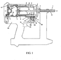
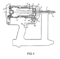
- chassis 100 chassis 100; nail tube 1; piston 2; piston rod 21; fixed core set 3; four-claw frame 4; cylinder 5; explosion cylinder 8; cylinder head 10; percussion switch device 20.
- chassis 100 chassis 100; nail tube 1; piston 2; piston rod 21; fixed core set 3; four-claw frame 4; cylinder 5; explosion cylinder 8; cylinder head 10; percussion switch device 20.
- chassis 100 chassis 100; nail tube 1; piston 2; piston rod 21; fixed core set 3; four-claw frame 4; cylinder 5; explosion cylinder 8; cylinder head 10; percussion switch device 20.
- chassis 100 with a comfortable handle for the user; it can install and accommodate various parts of nail gun. Understandably, chassis 100 is not a single part, but it is formed by many chassis parts. The shape of chassis 100 is symmetrical to the vertical center plane extended front and rear in the rough.
- Nail tube 1 can be installed at the top of front-side of chassis 100 by sliding front and rear, nail (not shown) can be inserted in the nail tube 1, for example, inserted into the inner hole from the front end of the nail tube 1, while the front end of piston rod 21 can enter into inner hole of nail tube from the front end of nail tube 1 and hit the nail, then shoot nail out forward.
- Fixed core set 3 has been concentrically installed in the back end of the nail tube 1.
- Fixed core set 3 has a fixed core hole aligned with the inner hole.
- the front end of piston rod 21 is inserted into fixed core hole of fixed core set 3 in order to enter the inner hole of the nail tube correctly.
- Four-claw frame 4 is fixed to the back end of fixed core set 3
- four-claw frame 4 has disc 41 adjacent to the back end of fixed core set 3 and four connecting arms 42 extending back from disc.
- the front of explosion cylinder 8 is fixed to the back-end of connecting arm 42 by using bolt 6, and the outer side of explosion cylinder 8 can match chassis 100 by sliding.
- Cylinder 5 is installed in the explosion cylinder 8. Like cylinder head 10, cylinder 5 is fixed in the chassis, so the location of two parts is relatively stationary.
- O-shaped sealing ring 7 is installed on the outer wall 53 of described back-end.
- a sealing is formed between above O-shaped sealing ring 7 and bulge 82 extended inward, thus cylinder 5 and cylinder head 10 will close explosion cylinder 8 (see FIG 3 ).
- O-shaped sealing ring 7 is disengaged from bulge 82 extended inward, thus cylinder 5 and cylinder head 10 will open explosion cylinder 8 (see FIG. 1 )
- One or more holes 52 penetrating the side are formed in the front of cylinder 5.
- One-way valve is installed in these holes 52 and therefore the air can flow out of cylinder 5 but can't flow into the cylinder.
- Piston 2 is fixed on the back end of piston rod 21, and can front-to-rear slide in the barrel of cylinder 5 with piston rod.
- the center lines of nail tube 1, fixed core set 3, four-claw frame 4, explosion cylinder 8, cylinder 5, piston 2, piston rod 21 and cylinder head 10 are collinear, namely they have collinear center line 0-0' extended along the front and back direction, as shown in FIG 1 .
- This center line 0-0' is located in the vertical center plane.
- Percussion switch device 20 is installed under the four-claw 4 in the chassis to control the firing operation of nail gun.
- Percussion switch device 20 includes percussion switch base 11, touch switch chip 12, ignition switch 14, trigger 15, and station-keeping U-shaped steel wire 17. Detailed instructions follow.
- Percussion switch base 11 includes two parallel base plates 112 and one pivot sleeve 111 vertical to these base plates, percussion switch base 111 is installed in the chassis 100 through pivot 19 of the pivot sleeve 111, pivot 19 is perpendicular to vertical center plane mentioned above, thus percussion switch base 11 can pivot around pivot 19. Described bases 112 have driving slot 113 extended downwards.
- Trigger 15 can be installed in the chassis by front-to-rear sliding, and expose buttoning part 151 used for buttoning backwards and pull part 152 stretched forward.
- the front of pull part 152 has two pull pins 153, and these pull pins 153 are inserted in the driving slot 113 of base 112.
- trigger 15 is pushed down to the forward stretched position by a built-in spring.
- the user pushes back and presses buttoning part 151 with a finger and trigger 5 moves backwards, thus pull pin 153 will make percussion switch base 11 rotate around pivot 19 and along the trigger direction (clockwise direction in FIG. 1 ).
- Touch switch chip 12 is installed between two base plates 112. One end of touch switch chip has pivot installation part 121, and another end is touch part 122. On pivot installation part 121, touch switch chip 12 can be pivoted installed in the position between two base plates 112 by using pin 16. Pin 16 is also perpendicular to above vertical center plane. Touch switch chip 12 extends backward and upward from other pivot installation part 121, thus touch part 122 extends backward from percussion switch base 11.
- Ignition switch 14 is installed between two base plates 112. Such ignition switch 14 is fixed on one or two base plates 112 by using screw 13, and is located under the touch switch chip 12. In order to locate ignition switch 14 between two base plates 112, there is guiding bulge on one or two sides of the bottom of ignition switch 14, this guiding bulge can be inserted in the guiding groove 115 formed in the inner wall of base plates 112 in order to locate the ignition switch 14 relative to the percussion switch base 11.
- Ignition switch 14 has a contact button 141 extended upward. Pressing contact button 141 can start the ignition switch 14.
- the middle part of touch switch chip 12 is joined on the contact button 141, so the touch switch chip 12 is located between stopping block 114 of percussion switch base 11 and contact button 141 of ignition switch 14, and can press contact button 141 by pivoting pin 16 relative to the ignition switch 14, to start ignition switch 14.
- Station-keeping U-shaped steel wire 17 is a one-piece with a jumper 172 formed by bending a steel wire and two arms extended backwards. Each of these two arms has end 171 which can be used for fixing station-keeping U-shaped steel wire 17 on the bottom of explosion cylinder 8.
- a jumper 172 formed by bending a steel wire and two arms extended backwards. Each of these two arms has end 171 which can be used for fixing station-keeping U-shaped steel wire 17 on the bottom of explosion cylinder 8.
- notches 116 are formed at the upper edge of two base plates 112 of percussion switch base 11. Touch part 122 described above extends to the top of touch surface. When the sliding components move to the back position, above notch 116 can push and press touch part 122, and snap the jumper 172 of station-keeping U-shaped steel wire 17, allowing the percussion switch base 11 to be pivoted along the triggering direction.
- trigger 15 can be pulled, and then ignition switch 14 can be started.
- trigger 15 can't be pulled, and then ignition switch 14 can't be started.
- percussion switch base 11 When the whole sliding component moves to the back position, as mentioned above, pulling the trigger 15 backwards will result in percussion switch base 11 moving around pivot 19 along the direction of triggering, percussion switch base 11 will take the touch switch chip 12 to this position, that is the touch part 122 of touch switch chip 12 touch the jumper 172 of station-keeping U-shaped steel wire 17.
- touch part 122 prevented by jumper 172 will press the contact button 141 of ignition switch 14, then start ignition switch 14.
- notch 116 at the back of upper edge of two base plates 112 of percussion switch base 11 will snap the jumper 172 of station-keeping U-shaped steel wire 17.
- each part In the state of nail gun being not operated, each part is located in the position as shown in FIG 1 , the sliding component formed by its nail tube 1, fixed core set 3, four-claw frame 4, explosion cylinder 8 and station-keeping steel wire 17 is located in the front side, and the explosion cylinder 8 is open.
- jumper 172 of station-keeping U-shaped steel wire 17 will be adjacent to the upper edge of two base plates 112 of percussion switch base 11, and thus the trigger 15 can't be pulled.
- the explosion cylinder (explosion chamber) can still be seen as a closed chamber relative to the outside at this time.
- High-temperature air in the closed explosion cylinder begins to cool and form a low pressure.
- the inner side of piston 2 forms a low pressure while outer side of piston is under the atmospheric pressure.
- piston 2 and piston rod 21 move backwards to reset, as shown in FIG 5 .
- jumper 172 of station-keeping U-shaped steel wire 17 continues to snap the notch 116 of percussion switch base 11 to prevent above sliding component moving forward, thus ensuring low pressure in the explosion cylinder until the piston and piston rod finish resetting.
- pulling trigger can only be done in the state of explosion cylinder being closed completely, and then percussion switch base 11 is turned and starts ignition switch 14.
- touch switch chip 12 starting ignition switch 14 and notch 116 of percussion switch base 11 snapping station-keeping U-shaped steel wire 17 can be done at the same time, or start ignition switch 14 to realize firing firstly, and then station-keeping U-shaped steel wire 17 is snapped by notch 116 of percussion switch base 11.
- This method effectively prevents the following unsafe operation: if firing after the notch 116 of percussion base 11 snapped station-keeping U-shaped steel wire 17, it is unsafe because nail tube may fire when leaving the working face.
- the fans equipped for explosion chamber can mix the blasted combustible gas and air.
- Preferable fan position is in the cylinder head 10.
- Preferable cylinder head 10 also has the nozzle used for introducing combustible gas into the explosion chamber.
- explosion cylinder 8 will connect the fan switch first when explosion cylinder moves backward, pulling the trigger and connecting the ignition switch.
- trigger 15 can be pulled one or more times.
- the combustible gas introduced into explosion chamber is quantitative, so the combustible gas in the explosion chamber can be lit once.
- nail tube must be pushed and pressed again to introduce combustible gas into the explosion chamber, then it can be lit again. Therefore, the utility model deflagration nail gun has greater security.
- the trigger can be pulled after pressing the nail tube. This avoids the risk mentioned above of safe detent device firing accidentally by using existing technologies.
- the trigger must be released first after firing, then the next pressing nail tube and pulling trigger can be done, thus providing twice the insurance measures compared to the technology of sequential tripping used in traditional technologies, and greatly enhancing the safety level.
Landscapes
- Engineering & Computer Science (AREA)
- Mechanical Engineering (AREA)
- Chemical & Material Sciences (AREA)
- Combustion & Propulsion (AREA)
- Portable Nailing Machines And Staplers (AREA)
Applications Claiming Priority (1)
| Application Number | Priority Date | Filing Date | Title |
|---|---|---|---|
| CN200920177314.3U CN201471378U (zh) | 2009-09-08 | 2009-09-08 | 爆燃式射钉枪 |
Publications (1)
| Publication Number | Publication Date |
|---|---|
| EP2292382A1 true EP2292382A1 (de) | 2011-03-09 |
Family
ID=42407619
Family Applications (1)
| Application Number | Title | Priority Date | Filing Date |
|---|---|---|---|
| EP09075514A Withdrawn EP2292382A1 (de) | 2009-09-08 | 2009-11-22 | Deflagrationsnagelpistole |
Country Status (3)
| Country | Link |
|---|---|
| US (1) | US20130186927A1 (de) |
| EP (1) | EP2292382A1 (de) |
| CN (1) | CN201471378U (de) |
Families Citing this family (4)
| Publication number | Priority date | Publication date | Assignee | Title |
|---|---|---|---|---|
| EP3037217A1 (de) * | 2014-12-23 | 2016-06-29 | HILTI Aktiengesellschaft | Nagelgerät |
| TWM563327U (zh) * | 2018-01-11 | 2018-07-11 | 永大霖企業股份有限公司 | 打釘槍之擊發切換裝置 |
| USD1015105S1 (en) * | 2021-12-21 | 2024-02-20 | Zhejiang Prulde Electric Appliance Co., Ltd. | Nail gun |
| CN119164705B (zh) * | 2024-11-13 | 2025-02-07 | 内蒙聚力工程爆破有限公司 | 一种矿山爆破取样设备 |
Citations (3)
| Publication number | Priority date | Publication date | Assignee | Title |
|---|---|---|---|---|
| US4483474A (en) * | 1981-01-22 | 1984-11-20 | Signode Corporation | Combustion gas-powered fastener driving tool |
| EP0738565A1 (de) * | 1995-04-19 | 1996-10-23 | Japan Power Fastening Co., Ltd. | Tragbares, gasbetätigtes Befestigungswerkzeug |
| EP1724066A1 (de) * | 2004-03-12 | 2006-11-22 | Max Co., Ltd. | Verbrennungsgasbetriebene nagelmaschine |
-
2009
- 2009-09-08 CN CN200920177314.3U patent/CN201471378U/zh not_active Expired - Fee Related
- 2009-11-17 US US12/619,697 patent/US20130186927A1/en not_active Abandoned
- 2009-11-22 EP EP09075514A patent/EP2292382A1/de not_active Withdrawn
Patent Citations (3)
| Publication number | Priority date | Publication date | Assignee | Title |
|---|---|---|---|---|
| US4483474A (en) * | 1981-01-22 | 1984-11-20 | Signode Corporation | Combustion gas-powered fastener driving tool |
| EP0738565A1 (de) * | 1995-04-19 | 1996-10-23 | Japan Power Fastening Co., Ltd. | Tragbares, gasbetätigtes Befestigungswerkzeug |
| EP1724066A1 (de) * | 2004-03-12 | 2006-11-22 | Max Co., Ltd. | Verbrennungsgasbetriebene nagelmaschine |
Also Published As
| Publication number | Publication date |
|---|---|
| CN201471378U (zh) | 2010-05-19 |
| US20130186927A1 (en) | 2013-07-25 |
Similar Documents
| Publication | Publication Date | Title |
|---|---|---|
| US8714145B2 (en) | Semiautomatic bullet firing mechanism and toy gun using it | |
| US9777980B2 (en) | Compact semi-automatic firearm | |
| US7896210B2 (en) | Fastener actuation system | |
| US20110041821A1 (en) | Toy dart launcher apparatus with momentary lock | |
| EP2292382A1 (de) | Deflagrationsnagelpistole | |
| US7708177B2 (en) | Powder-actuated fastener-driving tool | |
| US4565312A (en) | Powder actuated tool with safety | |
| TW200536686A (en) | Combustion gas nailing machine | |
| DE602005012450D1 (de) | Pistole mit entferntes-Magazin-Sicherheit | |
| TW201941882A (zh) | 無釘不可擊發的打釘槍 | |
| US10712120B1 (en) | Toy gun with foregrip | |
| TW200836891A (en) | Gas combustion type driving tool | |
| US6364190B1 (en) | Fastener driving tool with twist actuation | |
| ES312132A1 (es) | Dispositivo de lanzamiento de proyectiles, tacos, clavijas, clavos y otros objetos analogos | |
| WO2003002927A1 (en) | A trigger assembly | |
| US20060162712A1 (en) | Paintball gun | |
| US20070082308A1 (en) | Secure torch | |
| CA1057451A (en) | Gravity feed hot top tool | |
| TWI838083B (zh) | 具有多重保險的擊發火控系統 | |
| US7263796B2 (en) | Trigger system for hand firearms | |
| CN101528423A (zh) | 用于燃烧型射钉枪的充气循环功能 | |
| US10710226B2 (en) | Safe nail gun | |
| CN100567877C (zh) | 具有撞针保险和退壳器的手枪 | |
| US1376456A (en) | Automatic firearm | |
| CN209440102U (zh) | 一种大威力排钉型瓦斯射钉器 |
Legal Events
| Date | Code | Title | Description |
|---|---|---|---|
| PUAI | Public reference made under article 153(3) epc to a published international application that has entered the european phase |
Free format text: ORIGINAL CODE: 0009012 |
|
| AK | Designated contracting states |
Kind code of ref document: A1 Designated state(s): AT BE BG CH CY CZ DE DK EE ES FI FR GB GR HR HU IE IS IT LI LT LU LV MC MK MT NL NO PL PT RO SE SI SK SM TR |
|
| AX | Request for extension of the european patent |
Extension state: AL BA RS |
|
| 17P | Request for examination filed |
Effective date: 20110909 |
|
| RIC1 | Information provided on ipc code assigned before grant |
Ipc: B25C 1/08 20060101ALI20120216BHEP Ipc: B25C 1/00 20060101AFI20120216BHEP |
|
| GRAP | Despatch of communication of intention to grant a patent |
Free format text: ORIGINAL CODE: EPIDOSNIGR1 |
|
| STAA | Information on the status of an ep patent application or granted ep patent |
Free format text: STATUS: THE APPLICATION IS DEEMED TO BE WITHDRAWN |
|
| 18D | Application deemed to be withdrawn |
Effective date: 20120906 |