EP2292383B1 - Redundanter Überdrehzahlschutz für Elektrowerkzeuge - Google Patents
Redundanter Überdrehzahlschutz für Elektrowerkzeuge Download PDFInfo
- Publication number
- EP2292383B1 EP2292383B1 EP10175306.9A EP10175306A EP2292383B1 EP 2292383 B1 EP2292383 B1 EP 2292383B1 EP 10175306 A EP10175306 A EP 10175306A EP 2292383 B1 EP2292383 B1 EP 2292383B1
- Authority
- EP
- European Patent Office
- Prior art keywords
- motor
- switch
- detection module
- rotational speed
- power tool
- Prior art date
- Legal status (The legal status is an assumption and is not a legal conclusion. Google has not performed a legal analysis and makes no representation as to the accuracy of the status listed.)
- Active
Links
Images





Classifications
-
- H—ELECTRICITY
- H02—GENERATION; CONVERSION OR DISTRIBUTION OF ELECTRIC POWER
- H02P—CONTROL OR REGULATION OF ELECTRIC MOTORS, ELECTRIC GENERATORS OR DYNAMO-ELECTRIC CONVERTERS; CONTROLLING TRANSFORMERS, REACTORS OR CHOKE COILS
- H02P25/00—Arrangements or methods for the control of AC motors characterised by the kind of AC motor or by structural details
- H02P25/02—Arrangements or methods for the control of AC motors characterised by the kind of AC motor or by structural details characterised by the kind of motor
- H02P25/10—Commutator motors, e.g. repulsion motors
- H02P25/14—Universal motors
- H02P25/145—Universal motors whereby the speed is regulated by measuring the motor speed and comparing it with a given physical value, speed feedback
-
- B—PERFORMING OPERATIONS; TRANSPORTING
- B25—HAND TOOLS; PORTABLE POWER-DRIVEN TOOLS; MANIPULATORS
- B25F—COMBINATION OR MULTI-PURPOSE TOOLS NOT OTHERWISE PROVIDED FOR; DETAILS OR COMPONENTS OF PORTABLE POWER-DRIVEN TOOLS NOT PARTICULARLY RELATED TO THE OPERATIONS PERFORMED AND NOT OTHERWISE PROVIDED FOR
- B25F5/00—Details or components of portable power-driven tools not particularly related to the operations performed and not otherwise provided for
-
- H—ELECTRICITY
- H02—GENERATION; CONVERSION OR DISTRIBUTION OF ELECTRIC POWER
- H02H—EMERGENCY PROTECTIVE CIRCUIT ARRANGEMENTS
- H02H3/00—Emergency protective circuit arrangements for automatic disconnection directly responsive to an undesired change from normal electric working condition with or without subsequent reconnection ; integrated protection
- H02H3/02—Details
- H02H3/021—Details concerning the disconnection itself, e.g. at a particular instant, particularly at zero value of current, disconnection in a predetermined order
- H02H3/023—Details concerning the disconnection itself, e.g. at a particular instant, particularly at zero value of current, disconnection in a predetermined order by short-circuiting
-
- H—ELECTRICITY
- H02—GENERATION; CONVERSION OR DISTRIBUTION OF ELECTRIC POWER
- H02H—EMERGENCY PROTECTIVE CIRCUIT ARRANGEMENTS
- H02H3/00—Emergency protective circuit arrangements for automatic disconnection directly responsive to an undesired change from normal electric working condition with or without subsequent reconnection ; integrated protection
- H02H3/24—Emergency protective circuit arrangements for automatic disconnection directly responsive to an undesired change from normal electric working condition with or without subsequent reconnection ; integrated protection responsive to undervoltage or no-voltage
- H02H3/247—Emergency protective circuit arrangements for automatic disconnection directly responsive to an undesired change from normal electric working condition with or without subsequent reconnection ; integrated protection responsive to undervoltage or no-voltage having timing means
-
- H—ELECTRICITY
- H02—GENERATION; CONVERSION OR DISTRIBUTION OF ELECTRIC POWER
- H02H—EMERGENCY PROTECTIVE CIRCUIT ARRANGEMENTS
- H02H7/00—Emergency protective circuit arrangements specially adapted for specific types of electric machines or apparatus or for sectionalised protection of cable or line systems, and effecting automatic switching in the event of an undesired change from normal working conditions
- H02H7/08—Emergency protective circuit arrangements specially adapted for specific types of electric machines or apparatus or for sectionalised protection of cable or line systems, and effecting automatic switching in the event of an undesired change from normal working conditions for dynamo-electric motors
- H02H7/0827—Emergency protective circuit arrangements specially adapted for specific types of electric machines or apparatus or for sectionalised protection of cable or line systems, and effecting automatic switching in the event of an undesired change from normal working conditions for dynamo-electric motors responsive to underload or no-load, e.g. pump-off control circuits for pump motors
-
- H—ELECTRICITY
- H02—GENERATION; CONVERSION OR DISTRIBUTION OF ELECTRIC POWER
- H02K—DYNAMO-ELECTRIC MACHINES
- H02K7/00—Arrangements for handling mechanical energy structurally associated with dynamo-electric machines, e.g. structural association with mechanical driving motors or auxiliary dynamo-electric machines
- H02K7/14—Structural association with mechanical loads, e.g. with hand-held machine tools or fans
- H02K7/145—Hand-held machine tool
-
- H—ELECTRICITY
- H02—GENERATION; CONVERSION OR DISTRIBUTION OF ELECTRIC POWER
- H02P—CONTROL OR REGULATION OF ELECTRIC MOTORS, ELECTRIC GENERATORS OR DYNAMO-ELECTRIC CONVERTERS; CONTROLLING TRANSFORMERS, REACTORS OR CHOKE COILS
- H02P23/00—Arrangements or methods for the control of AC motors characterised by a control method other than vector control
- H02P23/26—Power factor control [PFC]
-
- H—ELECTRICITY
- H02—GENERATION; CONVERSION OR DISTRIBUTION OF ELECTRIC POWER
- H02P—CONTROL OR REGULATION OF ELECTRIC MOTORS, ELECTRIC GENERATORS OR DYNAMO-ELECTRIC CONVERTERS; CONTROLLING TRANSFORMERS, REACTORS OR CHOKE COILS
- H02P29/00—Arrangements for regulating or controlling electric motors, appropriate for both AC and DC motors
- H02P29/10—Arrangements for regulating or controlling electric motors, appropriate for both AC and DC motors for preventing overspeed or under speed
-
- H—ELECTRICITY
- H02—GENERATION; CONVERSION OR DISTRIBUTION OF ELECTRIC POWER
- H02P—CONTROL OR REGULATION OF ELECTRIC MOTORS, ELECTRIC GENERATORS OR DYNAMO-ELECTRIC CONVERTERS; CONTROLLING TRANSFORMERS, REACTORS OR CHOKE COILS
- H02P3/00—Arrangements for stopping or slowing electric motors, generators, or dynamo-electric converters
- H02P3/06—Arrangements for stopping or slowing electric motors, generators, or dynamo-electric converters for stopping or slowing an individual dynamo-electric motor or dynamo-electric converter
- H02P3/18—Arrangements for stopping or slowing electric motors, generators, or dynamo-electric converters for stopping or slowing an individual dynamo-electric motor or dynamo-electric converter for stopping or slowing an AC motor
- H02P3/22—Arrangements for stopping or slowing electric motors, generators, or dynamo-electric converters for stopping or slowing an individual dynamo-electric motor or dynamo-electric converter for stopping or slowing an AC motor by short-circuit or resistive braking
-
- H—ELECTRICITY
- H02—GENERATION; CONVERSION OR DISTRIBUTION OF ELECTRIC POWER
- H02P—CONTROL OR REGULATION OF ELECTRIC MOTORS, ELECTRIC GENERATORS OR DYNAMO-ELECTRIC CONVERTERS; CONTROLLING TRANSFORMERS, REACTORS OR CHOKE COILS
- H02P7/00—Arrangements for regulating or controlling the speed or torque of electric DC motors
-
- H—ELECTRICITY
- H02—GENERATION; CONVERSION OR DISTRIBUTION OF ELECTRIC POWER
- H02H—EMERGENCY PROTECTIVE CIRCUIT ARRANGEMENTS
- H02H7/00—Emergency protective circuit arrangements specially adapted for specific types of electric machines or apparatus or for sectionalised protection of cable or line systems, and effecting automatic switching in the event of an undesired change from normal working conditions
- H02H7/08—Emergency protective circuit arrangements specially adapted for specific types of electric machines or apparatus or for sectionalised protection of cable or line systems, and effecting automatic switching in the event of an undesired change from normal working conditions for dynamo-electric motors
- H02H7/093—Emergency protective circuit arrangements specially adapted for specific types of electric machines or apparatus or for sectionalised protection of cable or line systems, and effecting automatic switching in the event of an undesired change from normal working conditions for dynamo-electric motors against increase beyond, or decrease below, a predetermined level of rotational speed
Definitions
- the present disclosure relates to power tools and, more particularly, to an overspeed protective subsystem for power tools.
- US 5986417 discloses a sensorless universal motor controller.
- An overspeed protection subsystem is provided for a power tool having an electric motor.
- the overspeed protection subsystem is comprised of: a motor switch coupled in series with the motor; a motor control module interfaced with the motor switch and controls switching operation of the motor switch; and an overspeed detection module that determines rotational speed of the motor and disables the power tool when the rotational speed of the motor exceeds a threshold.
- the motor control module is interfaced with the phase-controlled switch and modulates the conductive state of the phase-controlled switch at a predetermined phase of the AC input signal.
- the overspeed detection module receives the predetermined phase from the motor control module and determines the rotational speed of the motor as a function of the predetermined phase and a measured current through the motor.
- FIG. 1 depicts a simplified circuit diagram of a motor control system 10 for controlling a motor in a power tool.
- the motor control system 10 is comprised generally of a power on/off switch 12, an electric motor 14, a motor switch 16 coupled in series with the motor 14, and a motor control module 18 interfaced with the motor switch 16.
- the motor is a universal motor and the motor switch is a triac but it is readily understood that other types of motors and switches fall within the scope of this disclosure.
- the motor may be an AC motor or DC motor, including brushed or brushless; whereas, the motor switch may be a field effect transistor (FET), an insulated gate bipolar transistor (IGBT), a silicon-controlled rectifier (SCR), or another type of electronic switch.
- FET field effect transistor
- IGBT insulated gate bipolar transistor
- SCR silicon-controlled rectifier
- the motor switch may also be replaced with an H-bridge, half-bridge or some other motor switching arrangement.
- the motor switch may be incorporated into the motor control module.
- the motor control system is connectable to a power source.
- the motor control system is connectable to an AC power source at AC main node and AC neutral node.
- the connection may be made in a conventional manner via a power cord to an AC outlet.
- the overspeed protection subsystem further described below is applicable to power tools having DC power sources as well.
- the motor control module 18 controls the amount of voltage applied to the motor 14 by controlling the switching operation of the motor switch 16.
- the term module may refer to, be part of, or include an electronic circuit, an Application Specific Integrated Circuit (ASIC), a processor (shared, dedicated, or group) and/or memory (shared, dedicated, or group) that execute one or more software or firmware programs, a combinational logic circuit, and/or other suitable components that provide the described functionality.
- ASIC Application Specific Integrated Circuit
- processor shared, dedicated, or group
- memory shared, dedicated, or group
- the motor control module 18 employs phase control to control the amount of voltage applied to the motor 14.
- operation of the motor 14 is controlled by switching the motor current on and off at periodic intervals in relation to the zero crossing of the AC input signal. These periodic intervals are caused to occur in synchronism with the waveform of the AC signal and are measured in terms of a conduction angle, measured as a number of degrees.
- the conduction angle determines the point within the AC waveform at which the motor switch is fired (i.e., closed), thereby delivering current to the motor.
- a conduction angle of 180° per half cycle corresponds to a condition of full or maximum conduction. That is, the motor switch 16 is fired such that current flows through the switch for the entire half cycle of the AC input signal.
- a 90° conduction angle commences current flow in the middle of the half cycle and thus half the available energy is delivered to the motor.
- the conduction angle is expressed as an angle from 0 to 180 degrees and determines the point at which the motor switch is fired.
- firing point the complement of conduction angle, which is expressed as an angle from 180 to 0 degrees. While the following description is provided with reference to phase control, it is readily understood that other motor control schemes (e.g., pulse width modulation) are within the broader aspects of this disclosure.
- the motor control system 10 further includes an overspeed protection subsystem 20.
- the overspeed protection subsystem 20 monitors the rotational speed of the motor 14 and disables the motor and/or the power tool when the rotational speed of the motor exceeds a threshold.
- the overspeed protective subsystem 20 is comprised of an overspeed detection module 22 and a disabling circuit 23. Different arrangements for the overspeed protection subsystem 20 are contemplated as will be further described below.
- a tachometer 21 is used to determine the rotational speed of the motor.
- the tachometer is disposed proximate to the motor 14 and configured to determine the rotational speed of the motor.
- An output signal indicative of speed is output from the tachometer into the overspeed detection module 22. It is readily understood that other types of sensors may be used to directly measure the speed of the motor.
- the overspeed protective subsystem 20 may employ indirect means for estimating the speed of the motor as further described below.
- the overspeed detection module 22 operates to determine when the rotational speed of the motor exceeds a threshold. Rotational speed of the motor is monitored at 122 using, for example, the input from tachometer 21. The rotational speed is then compared at 124 to a predefined threshold. When the rotational speed of the motor exceeds the threshold, the overspeed detection module 22 acts to disable the motor at 126; otherwise, motor speed continues to be monitored by the subsystem.
- the above functionality may be implemented by software instructions embedded in a microprocessor. It is to be understood that only the relevant steps of the methodology are discussed in relation to Figure 2 , but that other software instructions, or other electronic circuits, may be needed to control and manage the overall operation of the system. The above functionality may also be implemented exclusively using electronic circuits.
- the disable circuit 23 may include a protective switch 24, a circuit breaker 26 and/or a fuse 27.
- the protective switch 24 is connected across the AC line (i.e., coupled between the AC main line and the AC neutral or return line).
- a circuit breaker 26 and/or a fuse 27 are disposed in the circuit path between the AC power source and the protective switch.
- the overspeed detection module 22 closes the protective switch 24, thereby shorting the AC line. The sudden flow of current will trip the circuit breaker and/or blow the fuse, thereby disabling operation of the power tool.
- Protective switch 24 may be implemented using a field effect transistor (FET), an insulated gate bipolar transistor (IGBT), a silicon-controlled rectifier (SCR), a triac, a solid-state relay, a mechanical relay or another type of switch, with the required attendant circuitry.
- FET field effect transistor
- IGBT insulated gate bipolar transistor
- SCR silicon-controlled rectifier
- triac a solid-state relay
- mechanical relay or another type of switch
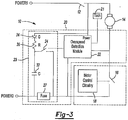
- FIG. 3 depicts an alternative embodiment for the disabling circuit 23.
- a capacitor 32 is placed in parallel with the protective switch 24.
- the capacitor 32 is charged through a diode 34 and a resistor 36 that limit the inrush of current into the capacitor.
- the overspeed detection module 22 detects an overspeed condition, it closes the protective switch 24.
- the energy stored in the capacitor 32 discharges into the fuse and thereby blows the fuse.
- the capacitor 32 may be replaced with or used in combination with other types of energy storing devices, such as inductors.
- the disabling circuit 23 may be reconfigured to support such devices.
- the overspeed protection subsystem 20 may operate independently from the motor control module 18, thereby providing a redundant safety feature.
- the overspeed protection subsystem 20 may operate cooperatively with the motor control module 18.
- the overspeed detection module 22 upon detecting an overspeed condition, provides a disabling signal to the motor control module 18.
- the motor control module 18 opens the motor switch 16 and thereby discontinues motor operation, thereby providing an additional or alternative technique for disabling the power tool.
- the overspeed detection module 22 may communicate with the motor control module 18 as the rotational speed of the motor approaches but before it exceeds the maximum speed threshold.
- the overspeed detection module 22 may issue a warning signal to the motor control module 18 when the rotational speed exceeds an intermediate speed threshold (e.g., define at 200 rpm less than the maximum speed threshold).
- the motor control module 18 may initiate protective actions to reduce the motor speed by varying the phase at which the motor switch is closed. In this way, the motor speed is reduced before the maximum speed threshold is reached, thereby averting the need to blow a fuse or otherwise disable the tool.
- FIG. 4 illustrates an exemplary implementation of the overspeed detection module 22.
- the overspeed detection module 22 is comprised of a signal conditioning circuit 41, a first voltage comparator 42, a bistable multivibrator, more commonly known as a flip-flop circuit 43, a frequency-to-voltage converter 44, a second voltage comparator 45 and a switch drive circuit 46. It is envisioned that one or more of these circuit components may be replaced with other circuit components that provide similar functions.
- a tachometer 21 is used to determine rotational speed of the motor.
- the tachometer may be further defined as a Hall effect sensor affixed to a non-moving reference frame and a magnet affixed to the rotating armature of the motor.
- the signal output by the tachometer 21 contains a fundamental frequency that is proportional to the rotational speed of the motor.
- Other implementations for the tachometer are also contemplated.
- the tachometer signal serves as input to the signal conditioning circuit 41.
- the signal conditioning circuit 41 operates to amplify or attenuate the signal from the tachometer 21, or to filter it as required by the nature of the signal or the noise environment.
- Output of the signal conditioning circuit 41 connects to the input of a first voltage comparator 42.
- First voltage comparator 42 operates to convert the analog input signal to a digital output signal. More specifically, the first voltage comparator produces a bi-level output depending upon the relative magnitude of the output signal from the signal conditioning circuit 41 in relation to a first reference voltage. When the analog input is greater than the reference voltage, then the output of the voltage comparator is low (i.e., the lesser of two output levels). When the analog input is less than the reference voltage, then the output of the voltage comparator is high.
- the first reference voltage may be adjusted as required to ensure an output of high integrity.
- Output of the first voltage comparator 42 serves an input to a flip-flop circuit 43. More specifically, a T or toggle flip-flop circuit is used to generate a digital signal having a 50% duty cycle. Output from the T flip-flop circuit is in turn input to a frequency-to-voltage converter 44. Output of the frequency-to-voltage converter 44 is a voltage proportional to the frequency of the input signal. In some embodiments, the frequency-to-voltage converter 44 may not require an input having a 50% duty cycle and thus the use of a T flip-flop circuit can be avoided.
- the voltage signal from the frequency-to-voltage converter 44 is compared to a reference voltage by a second voltage comparator 45.
- the reference voltage input to the second voltage comparator 45 is set to a value corresponding to a maximum speed threshold.
- a triggering signal is output to a switch drive circuit 46 which in turn closes the protective switch 24 in disabling circuit 23.
- the switch drive circuit 46 may include circuitry to ensure the output of the second voltage comparator 45 exceeds some time limit before the drive circuit 46 triggers the closing of the protective switch.
- Disabling circuit 23 operates in the manner set forth above to thereby short the AC line and disable operation of the power tool.
- the overspeed protection subsystem 20 may further include a motor switch protection circuit.
- the motor switch protection circuit monitors the switching operation of the motor switch 16 and initiates one or more protective operations to protect to the tool operator when the switching operation of the motor switch fails.
- the motor switch may fuse closed and cause the tool to operate at high speeds.
- Different arrangements for the motor switch protection circuit are set forth in U.S. Provisional Application No. 61/239,959, filed on September 4, 2009 .
- FIG. 5 depicts an overspeed protection subsystem 20 that integrates an exemplary motor switch protection circuit 50 with the overspeed detection module 22 described in Figure 4 .
- the exemplary motor switch protection circuit 50 is comprised of a signal conditioning circuit 51, a voltage comparator 52 and a monostable multivibrator 53.
- This motor switch protection circuit is exemplary in nature and one or more of its circuit components may be replaced with other circuit components that provide similar functions.
- the signal conditioning circuit 51 receives a measure of the voltage across the motor switch 16.
- the signal conditioning circuit 51 is further defined as an attenuator and/or a low-pass filter which may be differential or referenced to AC neutral. Output of the signal conditioning circuit 51 is input to the voltage comparator 52.
- voltage is expected to develop across the motor switch during the first few degrees of every AC cycle.
- some predetermined threshold e.g. 7 volts
- the motor switch e.g., a triac
- the voltage comparator 52 compares the voltage across the switch 16 to a reference voltage that is correlated to the threshold. When the voltage across the switch is greater than the reference voltage, then the output of the voltage comparator 52 is low (i.e., lesser of two output levels). When the voltage of the switch is less than the reference voltage, then the output of the voltage comparator 52 is high.
- the output of the voltage comparator serves as the input trigger to a negative recovery monostable multivibrator 53.
- the negative recovery monostable multivibrator 53 provides an output so long as trigger pulses continue to be received at the input. When trigger pulses cease to be received, within the time determined by the accessory components around the mutivibrator 53, then the output goes to the inactive state after the determined time. Being a digital device the negative recovery monostable multivibrator 53 has binary output. That output can be active low or active high as circumstances require. If we assume its output is active high then the negative recovery monostable multivibrator 53 will give an output high, for the time determined by accessory components, for a single input pulse. After that time its output will extinguish and revert to a low output state.
- the output of the negative recovery monostable multivibrator 53 serves as one input to a logic gate 55.
- the second input of the logic gate 55 is the output of the second voltage comparator 45 discussed below.
- Overspeed detection module 22 operates in the manner set forth in relation to Figure 4 with similar components having the same reference numbers.
- output from the second voltage comparator 45 and the monostable multivibrator 53 are input to a logic gate 55.
- the logic gate 55 When the inputs to the logic gate 55 indicate either an overspeed condition or a fused motor switch condition, the logic gate 55 will output a triggering signal to the switch drive circuit 46 which in turn closes the protective switch 24 of the disabling circuit.
- the switch drive circuit 46 may be implemented by a gated monostable multivibrator, where the output from the logic gate is a reset input to the multivibrator, the output from a zero-cross detection circuit is a triggering input to the multivibrator, and the output of the multivibrator drives a transistor that closes the protective switch.
- the switch drive circuit 46 may include circuitry to ensure the output of the logic gate 55 exceeds some time limit before the switch drive circuit triggers the closing of the protective switch.
- Disabling circuit 23 operates in the manner set forth above to thereby short the AC line disable operation of the power tool.
- FIG. 6 depicts an alternative implementation of the overspeed detection module 22 that uses a programmable microcontroller.
- Tachometer 21 is again used to determine rotational speed of the motor.
- the tachometric signal is preferably filtered by a filtering circuit (comprised of R6, R5 and C3) prior to being input to the microcontroller 62.
- the microcontroller 62 first converts the tachometric signal from an analog input signal to a digital signal.
- the microcontroller 62 employs an internal comparator to implement this function.
- the reference voltage for the internal comparator is developed across R11, R12 and C5 and input via a secondary input to the microcontroller 62.
- Output from the internal comparator is used as an interrupt to a free running counter.
- the value of the counter correlates to the period and thus the frequency of the tachometric signal.
- the frequency of the tachometric signal is proportional to the rotational speed of the motor. Consequently, performing a numeric division with the counter value yields a quotient that is proportional to rotational speed of the motor.
- the counter is reset after the interrupt to enable continual monitoring of speed.
- the microcontroller 62 compares the quotient to a predefined threshold having a value corresponding to a maximum speed limit. When the quotient (and thus the motor speed) exceeds the threshold, the microcontroller 62 closes the protective switch 24, thereby shorting the line and blowing the fuse. More specifically, the microcontroller 62 turns on switch Q1 which in turns closes the protective switch 24.
- An exemplary power supply circuit is comprised of diodes D1, D2, resistors R1, R2 and capacitors C1, C2.
- a fuse may not open within a single half-cycle of conduction
- operation of the microcontroller 62 is preferably synchronized to the AC line.
- a zero-cross detection circuit comprised of R4, R8, C4, D3, D4 and R9 enables the microcontroller 62 to synchronize with the AC line. With zero-crossing input, the microcontroller 62 is able to activate the protective switch 24 shortly after each AC line zero-cross, thereby ensuring the current will flow, sufficient to open the fuse. If one fuse does not meet the desired current rating, then two or more fuses may be placed in parallel to achieve the desired rating.
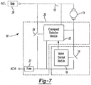
- Figure 7 depicts an exemplary embodiment of the overspeed detection module 22 that determines rotational speed of the motor without the use of a tachometer or other direct speed sensing system.
- the overspeed detection module 22 determines the rotational speed of the motor 14 indirectly from other system parameters.
- the overspeed detection module 22 is implemented preferably using a microcontroller although the microcontroller may be replaced in part or entirely by other types of circuit components that implement the functions set forth below.
- the overspeed detection module 22 receives a measure of current through the motor from a current sensor.
- the current sensor may be a resistor connected in series with the motor, such that the overspeed protection module 22 measures the voltage across the terminals of the resistor.
- the overspeed protection module 22 determines the rotational speed of the motor from the current measure.
- An exemplary technique for determining speed of the motor from a current measure is set forth in U.S. Patent No. 5,986,417 .
- the overspeed detection module 22 may also receive a measure of the voltage across the armature of the motor. In this case, the overspeed protection module 22 may determine the rotational speed of the motor 14 based on the measure of current through the motor as well as the voltage across the armature of the motor. This technique for determining speed is set forth in U.S. Patent No. 7,518,324 .
- the rotational speed of the motor is continually monitored by the overspeed detection module 22. Specifically, the rotational speed is compared to a predefined threshold in the manner described above. When the rotational speed of the motor exceeds the threshold, the overspeed detection module 22 acts to disable the motor 14; otherwise, the speed detection module 22 continues to monitor motor speed.
- the overspeed detection module 22 may be further configured to receive the conduction angle (or its complement, firing point) at which the motor switch is closed. In an alternative embodiment, the overspeed detection module 22 determines rotational speed of the motor as a function of the conduction angle and the measured current through the motor. Basis for this new technique for deriving rotational speed is further described below.
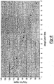
- Figure 8 illustrates the functional relationship between the firing point and the average current measure for a fixed speed.
- the exemplary curve in Figure 8 is an isotach of 1,000 rpm being measured at the output of the tool.
- the data can be fit with a mathematical expression or function. In this case, a fifth degree polynomial was used to represent the data.
- Figure 9 illustrates the functional relationship between firing point and the average current measure for various speed dial settings.
- a family of curves can be produced as shown in Figure 10 or a surface as shown in Figure 11A .
- One means to develop the family of curves in Figure 10 from the polynomials shown in Figure 9 is to interpolate between the various coefficients, (c I0A , c I0B , c I0C , c I0D ) ...
- Such a surface can be described by an equation like: + k FP 5 * FP 5 + k FP 4 * FP 4 + k FP 3 * FP 3 + k FP 2 * FP 2 + k FP 1 * FP , where speed is the rotational speed of the power tool, I is current as described above, FP is the firing point as described above, and k I0 - k I5 and k FP1 - k FP5 are constants determined according to some mathematical curve-fitting technique. It is understood that polynomials having different degrees may be used to fit the data and that curve fitting may be accomplished using known mathematical techniques. It is further understood that other functions besides polynomials may describe the relationship between current, firing point, and speed.
- tables of values may be used to describe functions and that interpolation between values in tables may also be incorporated. It is further understood that other measurements and parameters may be incorporated into a formula, a function, or a table for the purpose of determining speed other than the current and firing point used here to teach the method.
- speed may be derived as a function of two independent variables: firing point and average current. Given this functional relationship, rotational speed can be reliably computed from the firing point and average current for purposes of overspeed detection and protection. It is envisioned that this relationship may also be used for other purposes such as maintaining tool speed at a given set point.
- a given power tool is instrumented to collect the necessary parameters for computing the functional relationship between motor speed, firing point and average current for the given power tool or power tool family. This data is then used to derive one or more polynomials which may be used to compute motor speed and, more particularly, the coefficients for the polynomials. The polynomials are in turn used by an overspeed detection module 22 residing in the tool to implement overspeed protection.
- the overspeed detection module 22 is configured to receive the conduction angle (or its complement, firing point) at 121 from the motor control module 18. During motor operation, the motor control module 18 drives the conductive state of the motor switch 16 in accordance with a conduction angle computed for each AC line cycle. This conduction angle for each AC line cycle is reported to the overspeed detection module 22. The overspeed detection module 22 also measures the current through the motor during each AC line cycle as indicated at 122. Conduction angle and its corresponding current measure taken during the same AC line cycle are used to compute motor speed at 123 as further described below. In an exemplary embodiment, a predefined number of sampled current measurements are taken during a given AC line cycle and averaged to provide the current measure for the given AC line cycle.
- current measures are less reliable. Therefore, it is contemplated that current measures may be determined across multiple AC line cycles. For example, average current may be determined for a set number of line cycles (e.g., the preceding 32 line cycles) which are likewise averaged together to form a multi-cycle current measure.
- the multi-cycle current measure may be used in place of the one-cycle current measure when computing motor speed.
- the multi-cycle current measure has been shown to be a more stable and accurate measure of current through the motor, particularly at lower motor speeds.
- the speed detection module 22 uses a polynomial to compute motor speed, where the polynomial represents a surface such as the one shown in Figure 11B . Coefficients for the polynomial are stored in a memory device and accessible by the speed detection module. For each AC line cycle, the speed detection module 22 computes the motor speed using the conduction angle and current measure. The computed speed is compared to a predefined threshold that signifies a maximum speed limit for the tool. When the rotational speed of the motor exceeds the threshold, the overspeed detection module 22 acts to disable the motor; otherwise, the speed detection module continues to monitor and compute motor speed during each AC line cycle. It is envisioned that such computations may only occur every x number of AC line cycles, where x is an integer greater than or equal to 1.
- the speed detection module 22 may access a table, where each table entry represents a current limit correlated to a speed limit. For example, each value in the table is addressed by a conduction angle. Given a conduction angle, the speed detection module 22 accesses to the table to retrieve a current limit. The speed detection module may employ an interpolation method to compute the value that most closely correlates to the given conduction angle. The speed detection module 22 then compares the current measure to the retrieved current limit as indicated at 124. If the current limit exceeds the current measure, then motor speed is too high and the overspeed detection module acts to disable the motor at 125; otherwise, the speed detection module continues to monitor motor speed in this manner.
- the index for the table is a number from 0 to 255, being the firing point during the AC line cycle of the previous current measurement.
- the values in the table are current limits of various and sundry values, each value having been predetermined as appropriate for its particular firing point and thus for its conduction angle as well.
- the firing point index is added to the base address of the table to obtain the absolute address for the table value of interest.
- the output value of the table is the contents of memory pointed to by that absolute address. This output value is the current limit retrieved from the table, to be used for testing the measured current of the previous AC line cycle, as described above.
- This one-dimensional table is not meant to limit the scope of this invention. It is understood by those skilled in the art that two-dimensional tables or multi-dimensional tables may be employed with appropriate modifications.
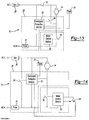
- Figure 13 illustrates another alternative circuit arrangement for the motor control system.
- the protective switch 24 is connected across the motor. This arrangement alleviates the need for sensing the state of the power on/off switch.
- the power on/off switch When the power on/off switch is off (i.e., open position), there is no voltage across the motor switch so that the protective control module closes the protective switch. Any current shorted around the motor is not sufficient to trip the breaker or blow the fuse when the power on/off switch is in an off position.
- the power on/off switch is on (i.e., closed position)
- the protective control module 22 operates in the manner described above in relation to Figure 1 .
- Preceding embodiments contemplate a power on/off switch that is disposed between the AC power source and the motor such that the power delivered to the motor is conducted through the power on/off switch.
- Figure 14 illustrates an alternative embodiment of an overspeed protection module that is suitable for use with a power on/off switch that does not conduct the power delivered to the motor.
- the power on/off switch 91 is interfaced with the motor control module 18 and provides an indicator thereto as to whether a user desires the tool to be operational or not.
- the motor control module 18 may in turn control the amount of voltage applied to the motor 14 in the manner described above.
- the power on/off switch 141 may be implemented as a push button, a sliding switch or some other type of "logic" switch. Rather than being connected across the AC line, it is also envisioned that the protective switch 24 may be connected across the motor 14.
Landscapes
- Engineering & Computer Science (AREA)
- Power Engineering (AREA)
- Mechanical Engineering (AREA)
- Control Of Ac Motors In General (AREA)
- Control Of Electric Motors In General (AREA)
Claims (11)
- Elektrowerkzeug mit einem Elektromotor (14), umfassend:einen Motorschalter (16), der mit dem Motor (14) in Reihe geschaltet ist;ein Motorsteuermodul (18), das mit dem Motorschalter (16) verbunden ist und einen Schaltbetrieb des Motorschalters (16) steuert; undein Überdrehzahlerkennungsmodul (22), das unabhängig vom Motorsteuermodul (18) zum Bestimmen einer Drehzahl des Motors (14) arbeitet und ein Signal an das Motorsteuermodul (18) ausgibt, wenn die Drehzahl des Motors (14) eine Schwelle übersteigt, dadurch gekennzeichnet, dass das Überdrehzahlerkennungsmodul (22) ein Abschaltsignal an das Motorsteuermodul (18) ausgibt, wobei das Motorsteuermodul (18) den Motorschalter (16) in Reaktion auf das Abschaltsignal vom Überdrehzahlerkennungsmodul (22) öffnet, wodurch der Betrieb des Motors (14) unterbrochen wird.
- Elektrowerkzeug nach Anspruch 1, wobei das Überdrehzahlerkennungsmodul (22) einen Tachometer (21) enthält, der nahe dem Motor (14) angeordnet und zum Bestimmen der Drehzahl des Motors (14) konfiguriert ist.
- Elektrowerkzeug nach Anspruch 1, wobei das Überdrehzahlerkennungsmodul (22) Strom durch den Motor (14) misst und die Drehzahl des Motors (14) auf Grundlage des gemessenen Stroms bestimmt.
- Elektrowerkzeug nach Anspruch 1, wobei das Elektrowerkzeug durch ein Wechselstrom- (WS-) Eingangssignal gespeist wird und der Schaltbetrieb des Motorschalters (16) an einer vorgegebenen Phase des WS-Eingangssignals auftritt.
- Elektrowerkzeug nach Anspruch 4, wobei das Überdrehzahlerkennungsmodul (22) die vorgegebene Phase vom Motorsteuermodul (18) empfängt, Strom durch den Motor (14) misst und die Drehzahl des Motors (14) in Abhängigkeit von der vorgegebenen Phase und des gemessenen Stroms bestimmt.
- Elektrowerkzeug nach Anspruch 4, ferner umfassend einen Schutzschalter (24), der über eine WS-Leitung, die das WS-Eingangssignal befördert, verbunden ist, und eine Sicherung (27), die in der WS-Leitung angeordnet ist, wobei das Überdrehzahlerkennungsmodul (22) den Schalter (24) schließt, wenn die Drehzahl des Motors (14) die Schwelle übersteigt, wodurch die WS-Leitung kurzgeschlossen und die Sicherung (27) geöffnet wird.
- Elektrowerkzeug nach Anspruch 4, ferner umfassend einen Schutzschalter (24), der über den Motor (14) verbunden ist, und eine Sicherung (27), die in der WS-Leitung angeordnet ist, wobei das Überdrehzahlerkennungsmodul (22) den Schalter (24) schließt, wenn die Drehzahl des Motors (14) die Schwelle übersteigt, wodurch die WS-Leitung kurzgeschlossen und die Sicherung (27) geöffnet wird.
- Elektrowerkzeug nach Anspruch 1, wobei das Überdrehzahlerkennungsmodul (22) zusammenwirkend mit dem Motorsteuermodul (18) zum Verringern der Drehzahl des Motors (14) arbeitet, wenn sich die Drehzahl des Motors (14) der maximalen Drehzahlschwelle annähert, jedoch darunter liegt.
- Elektrowerkzeug nach Anspruch 8, wobei das Überdrehzahlerkennungsmodul einen Tachometer (21) enthält, der nahe dem Motor (14) angeordnet und zum Bestimmen der Drehzahl des Motors (14) konfiguriert ist.
- Elektrowerkzeug nach Anspruch 8, wobei das Überdrehzahlerkennungsmodul (22) Strom durch den Motor (14) misst und die Drehzahl des Motors (14) auf Grundlage des gemessenen Stroms bestimmt.
- Elektrowerkzeug nach Anspruch 8, wobei das Elektrowerkzeug durch ein Wechselstrom- (WS-) Eingangssignal gespeist wird und der Schaltbetrieb des Motorschalters (16) an einer vorgegebenen Phase des WS-Eingangssignals auftritt.
Priority Applications (1)
| Application Number | Priority Date | Filing Date | Title |
|---|---|---|---|
| EP15170982.1A EP2939794B1 (de) | 2009-09-04 | 2010-09-03 | Elektrowerkzeug mit einem ubergeschwindigkeitsschutzmodul |
Applications Claiming Priority (1)
| Application Number | Priority Date | Filing Date | Title |
|---|---|---|---|
| US23995909P | 2009-09-04 | 2009-09-04 |
Related Child Applications (2)
| Application Number | Title | Priority Date | Filing Date |
|---|---|---|---|
| EP15170982.1A Division EP2939794B1 (de) | 2009-09-04 | 2010-09-03 | Elektrowerkzeug mit einem ubergeschwindigkeitsschutzmodul |
| EP15170982.1A Division-Into EP2939794B1 (de) | 2009-09-04 | 2010-09-03 | Elektrowerkzeug mit einem ubergeschwindigkeitsschutzmodul |
Publications (3)
| Publication Number | Publication Date |
|---|---|
| EP2292383A2 EP2292383A2 (de) | 2011-03-09 |
| EP2292383A3 EP2292383A3 (de) | 2014-10-08 |
| EP2292383B1 true EP2292383B1 (de) | 2016-04-06 |
Family
ID=42738853
Family Applications (4)
| Application Number | Title | Priority Date | Filing Date |
|---|---|---|---|
| EP10175306.9A Active EP2292383B1 (de) | 2009-09-04 | 2010-09-03 | Redundanter Überdrehzahlschutz für Elektrowerkzeuge |
| EP15170982.1A Not-in-force EP2939794B1 (de) | 2009-09-04 | 2010-09-03 | Elektrowerkzeug mit einem ubergeschwindigkeitsschutzmodul |
| EP15170897.1A Not-in-force EP2939793B1 (de) | 2009-09-04 | 2010-09-03 | Elektrowerkzeug mit einem schutzkontrollmodul |
| EP10175308.5A Not-in-force EP2292384B1 (de) | 2009-09-04 | 2010-09-03 | Schützendes redundantes Untersystem für Elektrowerkzeuge |
Family Applications After (3)
| Application Number | Title | Priority Date | Filing Date |
|---|---|---|---|
| EP15170982.1A Not-in-force EP2939794B1 (de) | 2009-09-04 | 2010-09-03 | Elektrowerkzeug mit einem ubergeschwindigkeitsschutzmodul |
| EP15170897.1A Not-in-force EP2939793B1 (de) | 2009-09-04 | 2010-09-03 | Elektrowerkzeug mit einem schutzkontrollmodul |
| EP10175308.5A Not-in-force EP2292384B1 (de) | 2009-09-04 | 2010-09-03 | Schützendes redundantes Untersystem für Elektrowerkzeuge |
Country Status (2)
| Country | Link |
|---|---|
| US (4) | US8476853B2 (de) |
| EP (4) | EP2292383B1 (de) |
Families Citing this family (62)
| Publication number | Priority date | Publication date | Assignee | Title |
|---|---|---|---|---|
| DE102010001241A1 (de) * | 2009-04-01 | 2010-10-07 | Robert Bosch Gmbh | Elektronisch kommutierter Elektromotor mit einer Notlaufeigenschaft |
| GB201006386D0 (en) | 2010-04-16 | 2010-06-02 | Dyson Technology Ltd | Control of a brushless motor |
| GB201006395D0 (en) | 2010-04-16 | 2010-06-02 | Dyson Technology Ltd | Control of a brushless motor |
| GB201006396D0 (en) | 2010-04-16 | 2010-06-02 | Dyson Technology Ltd | Control of a brushless motor |
| GB201006391D0 (en) | 2010-04-16 | 2010-06-02 | Dyson Technology Ltd | Control of a brushless permanent-magnet motor |
| GB201006387D0 (en) | 2010-04-16 | 2010-06-02 | Dyson Technology Ltd | Control of a brushless motor |
| GB201006392D0 (en) | 2010-04-16 | 2010-06-02 | Dyson Technology Ltd | Controller for a brushless motor |
| GB201006388D0 (en) | 2010-04-16 | 2010-06-02 | Dyson Technology Ltd | Control of brushless motor |
| GB201006397D0 (en) | 2010-04-16 | 2010-06-02 | Dyson Technology Ltd | Control of a brushless motor |
| GB201006398D0 (en) | 2010-04-16 | 2010-06-02 | Dyson Technology Ltd | Control of a brushless motor |
| GB201006390D0 (en) | 2010-04-16 | 2010-06-02 | Dyson Technology Ltd | Control of a brushless motor |
| GB201006384D0 (en) * | 2010-04-16 | 2010-06-02 | Dyson Technology Ltd | Control of a brushless motor |
| GB2484289B (en) | 2010-10-04 | 2013-11-20 | Dyson Technology Ltd | Control of an electrical machine |
| CN102147644B (zh) * | 2011-05-20 | 2013-09-25 | 华硕科技(苏州)有限公司 | 具有电压保护功能的连接器及主机板 |
| JP5653843B2 (ja) * | 2011-06-02 | 2015-01-14 | 株式会社マキタ | 動力工具 |
| US20140107853A1 (en) * | 2012-06-26 | 2014-04-17 | Black & Decker Inc. | System for enhancing power tools |
| US9367062B2 (en) * | 2012-12-31 | 2016-06-14 | Robert Bosch Gmbh | System and method for operational data retrieval from a power tool |
| US9209724B2 (en) | 2013-06-03 | 2015-12-08 | Black & Decker Inc. | Reverse rotation detection and overspeed protection for power tool with brushless motor |
| JP2015056928A (ja) * | 2013-09-10 | 2015-03-23 | 株式会社東芝 | 過充電保護装置 |
| US9762153B2 (en) * | 2013-10-18 | 2017-09-12 | Black & Decker Inc. | Cycle-by-cycle current limit for power tools having a brushless motor |
| US9314900B2 (en) | 2013-10-18 | 2016-04-19 | Black & Decker Inc. | Handheld grinder with a brushless electric motor |
| US9559628B2 (en) | 2013-10-25 | 2017-01-31 | Black & Decker Inc. | Handheld power tool with compact AC switch |
| CA2905725A1 (en) * | 2014-09-23 | 2016-03-23 | Emerson Electric Co. | Smart dc power supply for ac equipment |
| US10322498B2 (en) * | 2014-10-20 | 2019-06-18 | Makita Corporation | Electric power tool |
| WO2016100884A1 (en) | 2014-12-18 | 2016-06-23 | Black & Decker Inc. | Control scheme to increase tool usage as battery drains |
| US11260517B2 (en) | 2015-06-05 | 2022-03-01 | Ingersoll-Rand Industrial U.S., Inc. | Power tool housings |
| WO2016196984A1 (en) * | 2015-06-05 | 2016-12-08 | Ingersoll-Rand Company | Power tools with user-selectable operational modes |
| WO2016196918A1 (en) | 2015-06-05 | 2016-12-08 | Ingersoll-Rand Company | Power tool user interfaces |
| US10668614B2 (en) | 2015-06-05 | 2020-06-02 | Ingersoll-Rand Industrial U.S., Inc. | Impact tools with ring gear alignment features |
| WO2017079295A1 (en) | 2015-11-02 | 2017-05-11 | Black & Decker Inc. | Reducing noise and lowering harmonics in power tools using conduction band control schemes |
| US10486281B2 (en) | 2015-12-14 | 2019-11-26 | Milwaukee Electric Tool Corporation | Overload detection in a power tool |
| GB201603211D0 (en) * | 2016-02-24 | 2016-04-06 | Cooper Technologies Co | Voltage crowbar |
| JP6715046B2 (ja) * | 2016-03-22 | 2020-07-01 | Ntn株式会社 | 交流発電機のブレーキ装置 |
| US10589413B2 (en) * | 2016-06-20 | 2020-03-17 | Black & Decker Inc. | Power tool with anti-kickback control system |
| CN107520816B (zh) * | 2016-06-21 | 2020-01-14 | 苏州宝时得电动工具有限公司 | 动力工具的保护方法及系统 |
| EP3296063B1 (de) | 2016-06-24 | 2020-03-25 | Black & Decker Inc. | Steuerungsschema für ein elektrowerkzeug mit einem bürstenlosen motor |
| US10710220B2 (en) * | 2017-04-07 | 2020-07-14 | Black & Decker Inc. | Waveform shaping in power tool powered by alternating-current power supply |
| CN108736791B (zh) | 2017-04-20 | 2022-03-29 | 通用电气公司 | 车辆及其控制方法及系统 |
| US10833503B2 (en) | 2017-08-11 | 2020-11-10 | Black & Decker Inc. | Hardware control for prevention of dangerous restart in a power tool |
| CN109687780A (zh) * | 2017-08-25 | 2019-04-26 | 德昌电机(深圳)有限公司 | 电机及其驱动电路与驱动方法 |
| WO2019052664A1 (en) * | 2017-09-18 | 2019-03-21 | Electrolux Appliances Aktiebolag | METHOD OF OPERATING A LAUNDRY PROCESSING MACHINE, AND LAUNDRY PROCESSING MACHINE |
| CN110919600B (zh) * | 2018-09-18 | 2022-09-20 | 南京泉峰科技有限公司 | 电动工具及其启动方法 |
| CA3125087A1 (en) * | 2018-12-26 | 2020-07-02 | Makita Corporation | Electric work machine |
| US11234360B2 (en) | 2019-02-01 | 2022-02-01 | Cnh Industrial Canada, Ltd. | Drive and sensing system for agricultural agitator |
| JP7336264B2 (ja) * | 2019-05-29 | 2023-08-31 | 株式会社マキタ | バッテリパック |
| EP3750673B1 (de) * | 2019-06-10 | 2021-09-29 | Nanjing Chervon Industry Co., Ltd. | Elektrowerkzeug |
| US11326692B2 (en) | 2019-08-08 | 2022-05-10 | Sigma Powertrain, Inc. | Rotational control assembly for a vehicle transmission |
| EP3806273A1 (de) | 2019-10-11 | 2021-04-14 | Black & Decker Inc. | Elektrowerkzeug mit aufnahme von batteriepacks mit unterschiedlicher kapazität |
| JP7533033B2 (ja) * | 2020-08-31 | 2024-08-14 | ブラザー工業株式会社 | 加熱装置及び画像形成装置 |
| WO2022094851A1 (en) | 2020-11-05 | 2022-05-12 | Techtronic Cordless Gp | Power tool control system |
| US11855567B2 (en) | 2020-12-18 | 2023-12-26 | Black & Decker Inc. | Impact tools and control modes |
| CN112716024B (zh) * | 2021-01-15 | 2022-09-02 | 青岛海信日立空调系统有限公司 | 一种烘干机 |
| CN112987610A (zh) * | 2021-02-22 | 2021-06-18 | 福开尔(西安)电气有限公司 | 一种电力机车“1+1”双真空断路器自动应急控制系统 |
| US12095255B2 (en) * | 2021-03-23 | 2024-09-17 | Snap-On Incorporated | Overcurrent protection for electric motor |
| JP7661759B2 (ja) * | 2021-04-15 | 2025-04-15 | オムロン株式会社 | 処理装置 |
| CN221842456U (zh) * | 2021-04-26 | 2024-10-15 | 米沃奇电动工具公司 | 动力工具 |
| EP4433638A4 (de) * | 2021-11-15 | 2025-09-03 | Vestel Beyaz Esya Sanayi Ve Ticaret Anonim Sirketi | Betriebsverfahren für trockner |
| CN115551126A (zh) * | 2022-09-27 | 2022-12-30 | 江苏豪思生物科技有限公司 | 一种基于液相质谱离子源的过热保护方法及装置 |
| DE102023104757A1 (de) * | 2023-02-27 | 2024-08-29 | Pilz Gmbh & Co. Kg | Überspannungsschutzanordnung für ein elektrisches Gerät |
| EP4604382A4 (de) * | 2023-06-02 | 2026-03-25 | Nanjing Chervon Ind Co Ltd | Elektrowerkzeug |
| US12256928B1 (en) * | 2023-12-20 | 2025-03-25 | Lexington Medical, Inc. | Safety control algorithms for surgical devices, including safety control algorithms for surgical stapler devices, and associated systems, devices, and methods |
| DE102024105108B4 (de) * | 2024-02-23 | 2025-10-16 | Andreas Stihl Ag & Co. Kg | Handbedientes, motorbetriebenes Arbeitsgerät mit Motorsteuerschaltung |
Family Cites Families (55)
| Publication number | Priority date | Publication date | Assignee | Title |
|---|---|---|---|---|
| US3921047A (en) | 1973-04-02 | 1975-11-18 | Beckman Instruments Inc | Overspeed protection system for centrifuge apparatus |
| US3936710A (en) | 1973-06-04 | 1976-02-03 | Canon Kabushiki Kaisha | Synchronous drive control system for dc motor |
| US3883785A (en) | 1973-09-27 | 1975-05-13 | Nasa | Low speed phaselock speed control system |
| US3957329A (en) * | 1974-11-01 | 1976-05-18 | I-T-E Imperial Corporation | Fault-current limiter for high power electrical transmission systems |
| US4040117A (en) * | 1975-10-28 | 1977-08-02 | The Singer Company | Fast operating overload switching circuit for universal motors |
| DE3119794C2 (de) | 1981-05-19 | 1985-06-27 | Kautt & Bux Kg, 7000 Stuttgart | Schutzschaltungsanordnung für einen phasenanschnittgesteuerten oder -geregelten Elektromotor |
| US4409532A (en) * | 1981-11-06 | 1983-10-11 | General Electric Company | Start control arrangement for split phase induction motor |
| US4509102A (en) * | 1983-03-08 | 1985-04-02 | Canadian Patents & Dev. Limited | Voltage controlled current switch with short circuit protection |
| DE3432845A1 (de) | 1984-09-07 | 1986-03-20 | AKO-Werke GmbH & Co KG, 7988 Wangen | Überwachungsschaltung für einen Universalmotor |
| US4629980A (en) | 1985-05-28 | 1986-12-16 | International Business Machines Corporation | Testing limits of speed variations in motors |
| US4622500A (en) | 1985-07-11 | 1986-11-11 | The Machlett Laboratories, Inc. | Electric motor controller |
| US4772977A (en) * | 1985-10-23 | 1988-09-20 | Fts, Inc. | System for protection of electrical machines against damage from residual voltage effects |
| US4710841A (en) * | 1985-10-23 | 1987-12-01 | Bottrell Gerald W | System for production of induction machines against damage from residual voltage effects |
| US4709195A (en) | 1986-09-12 | 1987-11-24 | Spectra-Physics, Inc. | Bar code scanner with DC brushless motor |
| US4926281A (en) * | 1989-02-27 | 1990-05-15 | Triplex | Fail-safe and fault-tolerant alternating current output circuit |
| US4958118A (en) * | 1989-08-28 | 1990-09-18 | A. O. Smith Corporation | Wide range, self-starting single phase motor speed control |
| DE4021559C1 (en) | 1990-07-06 | 1991-12-05 | Telefunken Electronic Gmbh, 7100 Heilbronn, De | Hand-held electrical power tool with triac controlling motor - has current detecting circuit releasing reset pulse for counter during each half wave of mains voltage |
| US5347205A (en) * | 1992-09-11 | 1994-09-13 | Hamilton Beach/ Proctor-Silex, Inc. | Speed and mode control for a blender |
| US5365157A (en) * | 1994-01-07 | 1994-11-15 | Coltene/Whaledent, Inc. | Voltage regulator employing a triac to deliver voltage to a load |
| US5670852A (en) | 1994-01-18 | 1997-09-23 | Micropump, Inc. | Pump motor and motor control |
| US5650728A (en) * | 1995-04-03 | 1997-07-22 | Hubbell Incorporated | Fault detection system including a capacitor for generating a pulse and a processor for determining admittance versus frequency of a reflected pulse |
| US5986417A (en) | 1995-04-26 | 1999-11-16 | Sgs-Thomson Mocroelectronics S.A. | Sensorless universal motor speed controller |
| US5617288A (en) * | 1995-06-05 | 1997-04-01 | Leviton Manufacturing Co., In. | Automatic surge suppressor disconnect protection system |
| US5666254A (en) * | 1995-09-14 | 1997-09-09 | Raychem Corporation | Voltage sensing overcurrent protection circuit |
| JP3533874B2 (ja) * | 1996-10-18 | 2004-05-31 | 日立工機株式会社 | オーバースピード保護装置を有する遠心機 |
| US6556410B1 (en) * | 1998-07-24 | 2003-04-29 | American Power Conversion, Inc. | Universal surge protector for notebook computers |
| US6236546B1 (en) * | 1999-08-16 | 2001-05-22 | Harris Corporation | Crowbar circuit verification testing system |
| JPWO2002094527A1 (ja) * | 2001-05-21 | 2004-09-02 | 三菱マテリアル株式会社 | 穿孔装置及び穿孔工法 |
| US20040090195A1 (en) | 2001-06-11 | 2004-05-13 | Motsenbocker Marvin A. | Efficient control, monitoring and energy devices for vehicles such as watercraft |
| EP1586160A2 (de) * | 2003-01-24 | 2005-10-19 | Tecumseh Products Company | Regelungssystem eines bürsten- und sensorlosen gleichstrommotors mit erkennung von festgefahrenem und angehaltenem rotor |
| KR100702913B1 (ko) * | 2003-03-17 | 2007-04-03 | 마쯔시다덴기산교 가부시키가이샤 | 브러시리스 dc 모터의 구동 방법 및 그 장치 |
| DE10317636A1 (de) | 2003-04-17 | 2004-11-25 | Robert Bosch Gmbh | Bremseinrichtung für einen Elektromotor |
| US7102303B2 (en) * | 2003-04-30 | 2006-09-05 | Black & Decker Inc. | Generic motor control system and method |
| US7075327B2 (en) * | 2003-06-18 | 2006-07-11 | Eaton Corporation | System and method for proactive motor wellness diagnosis |
| DE10353302A1 (de) | 2003-11-11 | 2005-06-09 | C. & E. Fein Gmbh | Elektrowerkzeug und Verfahren zur Steuerung eines Elektrowerkzeugs |
| FI116175B (fi) * | 2003-12-19 | 2005-09-30 | Abb Oy | Menetelmä ja järjestely taajuusmuuttajan suojaamiseksi |
| DE102004004170A1 (de) * | 2004-01-28 | 2005-08-18 | Robert Bosch Gmbh | Verfahren zur Abschaltung einer Elektrowerkzeugmaschine in einem Blockierfall und Elektrowerkzeugmaschine |
| DE102004018966B4 (de) | 2004-04-13 | 2015-02-19 | C. & E. Fein Gmbh | Reihenschlussmotor |
| JP4513536B2 (ja) * | 2004-12-06 | 2010-07-28 | 株式会社豊田自動織機 | インバータ装置 |
| US7292437B2 (en) * | 2005-01-10 | 2007-11-06 | Alan Mark Cohen | Heat dissipation assembly for computing devices |
| JP2006230169A (ja) * | 2005-02-21 | 2006-08-31 | Toshiba Corp | 同期機の制御装置 |
| US7551411B2 (en) * | 2005-10-12 | 2009-06-23 | Black & Decker Inc. | Control and protection methodologies for a motor control module |
| US7446493B2 (en) * | 2005-10-12 | 2008-11-04 | Black & Decker Inc. | Control methodologies for a motor control module |
| DE602006013863D1 (de) * | 2005-11-04 | 2010-06-02 | Bosch Gmbh Robert | Verfahren und vorrichtung für einen gelenkbohrer |
| US7518324B2 (en) | 2006-01-06 | 2009-04-14 | Stmicroelectronics, Inc. | Universal motor speed controller |
| US7990093B2 (en) * | 2006-04-20 | 2011-08-02 | Mitsubishi Electric Corporation | Electric motor control apparatus |
| JP4909797B2 (ja) * | 2007-04-24 | 2012-04-04 | 本田技研工業株式会社 | モータ制御装置 |
| US8076873B1 (en) * | 2007-06-01 | 2011-12-13 | Mtd Products Inc | Hybrid outdoor power equipment |
| JP2009002226A (ja) * | 2007-06-21 | 2009-01-08 | Yazaki Corp | ロック復帰制御装置及びロック復帰制御方法 |
| JP5376392B2 (ja) * | 2008-02-14 | 2013-12-25 | 日立工機株式会社 | 電動工具 |
| US8027572B2 (en) * | 2008-02-22 | 2011-09-27 | Baxter International Inc. | Dialysis machine having multiple line voltage heater |
| US8274866B2 (en) * | 2009-03-11 | 2012-09-25 | Konica Minolta Opto, Inc. | Optical recording head and optical recording apparatus |
| IN2012DN01903A (de) * | 2009-08-07 | 2015-07-24 | Shimizu Construction Co Ltd | |
| CN102753782B (zh) * | 2010-01-07 | 2015-09-30 | 布莱克和戴克公司 | 具有旋转输入控制的电动螺丝起子 |
| US8736208B2 (en) * | 2010-03-29 | 2014-05-27 | Jtekt Corporation | Motor control device |
-
2010
- 2010-09-03 EP EP10175306.9A patent/EP2292383B1/de active Active
- 2010-09-03 EP EP15170982.1A patent/EP2939794B1/de not_active Not-in-force
- 2010-09-03 US US12/875,354 patent/US8476853B2/en not_active Expired - Fee Related
- 2010-09-03 EP EP15170897.1A patent/EP2939793B1/de not_active Not-in-force
- 2010-09-03 US US12/875,504 patent/US9071188B2/en active Active
- 2010-09-03 EP EP10175308.5A patent/EP2292384B1/de not_active Not-in-force
-
2013
- 2013-02-28 US US13/779,821 patent/US9240747B2/en active Active
-
2015
- 2015-06-19 US US14/744,599 patent/US9722525B2/en active Active
Also Published As
| Publication number | Publication date |
|---|---|
| EP2292383A2 (de) | 2011-03-09 |
| EP2292383A3 (de) | 2014-10-08 |
| EP2292384A3 (de) | 2014-10-08 |
| EP2939793A1 (de) | 2015-11-04 |
| US8476853B2 (en) | 2013-07-02 |
| EP2939794B1 (de) | 2017-03-08 |
| EP2939793B1 (de) | 2017-03-08 |
| EP2292384B1 (de) | 2016-04-06 |
| EP2939794A1 (de) | 2015-11-04 |
| US9071188B2 (en) | 2015-06-30 |
| US20110058288A1 (en) | 2011-03-10 |
| US9722525B2 (en) | 2017-08-01 |
| US20110056715A1 (en) | 2011-03-10 |
| US20150288250A1 (en) | 2015-10-08 |
| US9240747B2 (en) | 2016-01-19 |
| EP2292384A2 (de) | 2011-03-09 |
| US20130169199A1 (en) | 2013-07-04 |
Similar Documents
| Publication | Publication Date | Title |
|---|---|---|
| EP2292383B1 (de) | Redundanter Überdrehzahlschutz für Elektrowerkzeuge | |
| AU2014255502B2 (en) | Vacuum cleaner with diagnostics | |
| EP1777792B1 (de) | Regelungs- und Schutzverfahren für ein Motorregelungssmodul | |
| KR101037147B1 (ko) | 스위치드 릴럭턴스 드라이브의 회전자 위치 검출 | |
| WO2007044930A2 (en) | Control and protection methodologies for a motor control module | |
| KR100970175B1 (ko) | 스위치드 릴럭턴스 드라이브의 회전자 위치 검출 방법 및장치 | |
| CN103760429A (zh) | 电机驱动装置及其缺相检测方法、系统 | |
| CN201248022Y (zh) | 具有电机控制模块的电动工具 | |
| CN116995616A (zh) | 一种电机保护方法、保护装置及计算机可读介质 | |
| KR930015240A (ko) | 3상 압축기의 과열 보호 회로 | |
| CN111010065A (zh) | 一种电机保护方法及装置、破壁料理机和存储介质 | |
| JPS6022570B2 (ja) | 電子式電動機保護リレ−のための欠相および無電流状態検出器 | |
| CN114609542B (zh) | 电源测量控制电路及机器人控制器 | |
| AU2004211178B2 (en) | Switch sensing to prevent inadvertent motor startup | |
| AU2005260241A1 (en) | Appliance fault monitor | |
| CN218335453U (zh) | 处理组件 | |
| CN115184636A (zh) | 一种直流电机转速实时估算电路及方法 | |
| JPH03164024A (ja) | モータの過負荷保護方法 | |
| JPH10216058A (ja) | 掃除機 |
Legal Events
| Date | Code | Title | Description |
|---|---|---|---|
| PUAI | Public reference made under article 153(3) epc to a published international application that has entered the european phase |
Free format text: ORIGINAL CODE: 0009012 |
|
| AK | Designated contracting states |
Kind code of ref document: A2 Designated state(s): AL AT BE BG CH CY CZ DE DK EE ES FI FR GB GR HR HU IE IS IT LI LT LU LV MC MK MT NL NO PL PT RO SE SI SK SM TR |
|
| AX | Request for extension of the european patent |
Extension state: BA ME RS |
|
| PUAL | Search report despatched |
Free format text: ORIGINAL CODE: 0009013 |
|
| AK | Designated contracting states |
Kind code of ref document: A3 Designated state(s): AL AT BE BG CH CY CZ DE DK EE ES FI FR GB GR HR HU IE IS IT LI LT LU LV MC MK MT NL NO PL PT RO SE SI SK SM TR |
|
| AX | Request for extension of the european patent |
Extension state: BA ME RS |
|
| RIC1 | Information provided on ipc code assigned before grant |
Ipc: H02P 6/08 20060101ALI20140903BHEP Ipc: B25F 5/00 20060101AFI20140903BHEP |
|
| 17P | Request for examination filed |
Effective date: 20150402 |
|
| RBV | Designated contracting states (corrected) |
Designated state(s): AL AT BE BG CH CY CZ DE DK EE ES FI FR GB GR HR HU IE IS IT LI LT LU LV MC MK MT NL NO PL PT RO SE SI SK SM TR |
|
| GRAP | Despatch of communication of intention to grant a patent |
Free format text: ORIGINAL CODE: EPIDOSNIGR1 |
|
| INTG | Intention to grant announced |
Effective date: 20160105 |
|
| GRAS | Grant fee paid |
Free format text: ORIGINAL CODE: EPIDOSNIGR3 |
|
| GRAA | (expected) grant |
Free format text: ORIGINAL CODE: 0009210 |
|
| AK | Designated contracting states |
Kind code of ref document: B1 Designated state(s): AL AT BE BG CH CY CZ DE DK EE ES FI FR GB GR HR HU IE IS IT LI LT LU LV MC MK MT NL NO PL PT RO SE SI SK SM TR |
|
| REG | Reference to a national code |
Ref country code: GB Ref legal event code: FG4D |
|
| REG | Reference to a national code |
Ref country code: AT Ref legal event code: REF Ref document number: 787222 Country of ref document: AT Kind code of ref document: T Effective date: 20160415 Ref country code: CH Ref legal event code: EP |
|
| REG | Reference to a national code |
Ref country code: IE Ref legal event code: FG4D |
|
| REG | Reference to a national code |
Ref country code: DE Ref legal event code: R096 Ref document number: 602010031999 Country of ref document: DE |
|
| REG | Reference to a national code |
Ref country code: LT Ref legal event code: MG4D Ref country code: NL Ref legal event code: MP Effective date: 20160406 |
|
| REG | Reference to a national code |
Ref country code: AT Ref legal event code: MK05 Ref document number: 787222 Country of ref document: AT Kind code of ref document: T Effective date: 20160406 |
|
| PG25 | Lapsed in a contracting state [announced via postgrant information from national office to epo] |
Ref country code: NL Free format text: LAPSE BECAUSE OF FAILURE TO SUBMIT A TRANSLATION OF THE DESCRIPTION OR TO PAY THE FEE WITHIN THE PRESCRIBED TIME-LIMIT Effective date: 20160406 |
|
| PG25 | Lapsed in a contracting state [announced via postgrant information from national office to epo] |
Ref country code: IS Free format text: LAPSE BECAUSE OF FAILURE TO SUBMIT A TRANSLATION OF THE DESCRIPTION OR TO PAY THE FEE WITHIN THE PRESCRIBED TIME-LIMIT Effective date: 20160806 Ref country code: PL Free format text: LAPSE BECAUSE OF FAILURE TO SUBMIT A TRANSLATION OF THE DESCRIPTION OR TO PAY THE FEE WITHIN THE PRESCRIBED TIME-LIMIT Effective date: 20160406 Ref country code: FI Free format text: LAPSE BECAUSE OF FAILURE TO SUBMIT A TRANSLATION OF THE DESCRIPTION OR TO PAY THE FEE WITHIN THE PRESCRIBED TIME-LIMIT Effective date: 20160406 Ref country code: NO Free format text: LAPSE BECAUSE OF FAILURE TO SUBMIT A TRANSLATION OF THE DESCRIPTION OR TO PAY THE FEE WITHIN THE PRESCRIBED TIME-LIMIT Effective date: 20160706 Ref country code: LT Free format text: LAPSE BECAUSE OF FAILURE TO SUBMIT A TRANSLATION OF THE DESCRIPTION OR TO PAY THE FEE WITHIN THE PRESCRIBED TIME-LIMIT Effective date: 20160406 |
|
| PG25 | Lapsed in a contracting state [announced via postgrant information from national office to epo] |
Ref country code: HR Free format text: LAPSE BECAUSE OF FAILURE TO SUBMIT A TRANSLATION OF THE DESCRIPTION OR TO PAY THE FEE WITHIN THE PRESCRIBED TIME-LIMIT Effective date: 20160406 Ref country code: SE Free format text: LAPSE BECAUSE OF FAILURE TO SUBMIT A TRANSLATION OF THE DESCRIPTION OR TO PAY THE FEE WITHIN THE PRESCRIBED TIME-LIMIT Effective date: 20160406 Ref country code: PT Free format text: LAPSE BECAUSE OF FAILURE TO SUBMIT A TRANSLATION OF THE DESCRIPTION OR TO PAY THE FEE WITHIN THE PRESCRIBED TIME-LIMIT Effective date: 20160808 Ref country code: ES Free format text: LAPSE BECAUSE OF FAILURE TO SUBMIT A TRANSLATION OF THE DESCRIPTION OR TO PAY THE FEE WITHIN THE PRESCRIBED TIME-LIMIT Effective date: 20160406 Ref country code: LV Free format text: LAPSE BECAUSE OF FAILURE TO SUBMIT A TRANSLATION OF THE DESCRIPTION OR TO PAY THE FEE WITHIN THE PRESCRIBED TIME-LIMIT Effective date: 20160406 Ref country code: AT Free format text: LAPSE BECAUSE OF FAILURE TO SUBMIT A TRANSLATION OF THE DESCRIPTION OR TO PAY THE FEE WITHIN THE PRESCRIBED TIME-LIMIT Effective date: 20160406 Ref country code: GR Free format text: LAPSE BECAUSE OF FAILURE TO SUBMIT A TRANSLATION OF THE DESCRIPTION OR TO PAY THE FEE WITHIN THE PRESCRIBED TIME-LIMIT Effective date: 20160707 |
|
| PG25 | Lapsed in a contracting state [announced via postgrant information from national office to epo] |
Ref country code: IT Free format text: LAPSE BECAUSE OF FAILURE TO SUBMIT A TRANSLATION OF THE DESCRIPTION OR TO PAY THE FEE WITHIN THE PRESCRIBED TIME-LIMIT Effective date: 20160406 Ref country code: BE Free format text: LAPSE BECAUSE OF FAILURE TO SUBMIT A TRANSLATION OF THE DESCRIPTION OR TO PAY THE FEE WITHIN THE PRESCRIBED TIME-LIMIT Effective date: 20160406 |
|
| REG | Reference to a national code |
Ref country code: DE Ref legal event code: R097 Ref document number: 602010031999 Country of ref document: DE |
|
| PG25 | Lapsed in a contracting state [announced via postgrant information from national office to epo] |
Ref country code: EE Free format text: LAPSE BECAUSE OF FAILURE TO SUBMIT A TRANSLATION OF THE DESCRIPTION OR TO PAY THE FEE WITHIN THE PRESCRIBED TIME-LIMIT Effective date: 20160406 Ref country code: CZ Free format text: LAPSE BECAUSE OF FAILURE TO SUBMIT A TRANSLATION OF THE DESCRIPTION OR TO PAY THE FEE WITHIN THE PRESCRIBED TIME-LIMIT Effective date: 20160406 Ref country code: RO Free format text: LAPSE BECAUSE OF FAILURE TO SUBMIT A TRANSLATION OF THE DESCRIPTION OR TO PAY THE FEE WITHIN THE PRESCRIBED TIME-LIMIT Effective date: 20160406 Ref country code: DK Free format text: LAPSE BECAUSE OF FAILURE TO SUBMIT A TRANSLATION OF THE DESCRIPTION OR TO PAY THE FEE WITHIN THE PRESCRIBED TIME-LIMIT Effective date: 20160406 Ref country code: SK Free format text: LAPSE BECAUSE OF FAILURE TO SUBMIT A TRANSLATION OF THE DESCRIPTION OR TO PAY THE FEE WITHIN THE PRESCRIBED TIME-LIMIT Effective date: 20160406 |
|
| PLBE | No opposition filed within time limit |
Free format text: ORIGINAL CODE: 0009261 |
|
| STAA | Information on the status of an ep patent application or granted ep patent |
Free format text: STATUS: NO OPPOSITION FILED WITHIN TIME LIMIT |
|
| PG25 | Lapsed in a contracting state [announced via postgrant information from national office to epo] |
Ref country code: SM Free format text: LAPSE BECAUSE OF FAILURE TO SUBMIT A TRANSLATION OF THE DESCRIPTION OR TO PAY THE FEE WITHIN THE PRESCRIBED TIME-LIMIT Effective date: 20160406 |
|
| 26N | No opposition filed |
Effective date: 20170110 |
|
| PG25 | Lapsed in a contracting state [announced via postgrant information from national office to epo] |
Ref country code: MC Free format text: LAPSE BECAUSE OF FAILURE TO SUBMIT A TRANSLATION OF THE DESCRIPTION OR TO PAY THE FEE WITHIN THE PRESCRIBED TIME-LIMIT Effective date: 20160406 |
|
| REG | Reference to a national code |
Ref country code: CH Ref legal event code: PL |
|
| PG25 | Lapsed in a contracting state [announced via postgrant information from national office to epo] |
Ref country code: SI Free format text: LAPSE BECAUSE OF FAILURE TO SUBMIT A TRANSLATION OF THE DESCRIPTION OR TO PAY THE FEE WITHIN THE PRESCRIBED TIME-LIMIT Effective date: 20160406 |
|
| REG | Reference to a national code |
Ref country code: IE Ref legal event code: MM4A |
|
| REG | Reference to a national code |
Ref country code: FR Ref legal event code: ST Effective date: 20170531 |
|
| PG25 | Lapsed in a contracting state [announced via postgrant information from national office to epo] |
Ref country code: IE Free format text: LAPSE BECAUSE OF NON-PAYMENT OF DUE FEES Effective date: 20160903 Ref country code: CH Free format text: LAPSE BECAUSE OF NON-PAYMENT OF DUE FEES Effective date: 20160930 Ref country code: FR Free format text: LAPSE BECAUSE OF NON-PAYMENT OF DUE FEES Effective date: 20160930 Ref country code: LI Free format text: LAPSE BECAUSE OF NON-PAYMENT OF DUE FEES Effective date: 20160930 |
|
| PG25 | Lapsed in a contracting state [announced via postgrant information from national office to epo] |
Ref country code: LU Free format text: LAPSE BECAUSE OF NON-PAYMENT OF DUE FEES Effective date: 20160903 |
|
| PG25 | Lapsed in a contracting state [announced via postgrant information from national office to epo] |
Ref country code: CY Free format text: LAPSE BECAUSE OF FAILURE TO SUBMIT A TRANSLATION OF THE DESCRIPTION OR TO PAY THE FEE WITHIN THE PRESCRIBED TIME-LIMIT Effective date: 20160406 Ref country code: HU Free format text: LAPSE BECAUSE OF FAILURE TO SUBMIT A TRANSLATION OF THE DESCRIPTION OR TO PAY THE FEE WITHIN THE PRESCRIBED TIME-LIMIT; INVALID AB INITIO Effective date: 20100903 |
|
| PG25 | Lapsed in a contracting state [announced via postgrant information from national office to epo] |
Ref country code: MT Free format text: LAPSE BECAUSE OF NON-PAYMENT OF DUE FEES Effective date: 20160930 Ref country code: TR Free format text: LAPSE BECAUSE OF FAILURE TO SUBMIT A TRANSLATION OF THE DESCRIPTION OR TO PAY THE FEE WITHIN THE PRESCRIBED TIME-LIMIT Effective date: 20160406 Ref country code: MK Free format text: LAPSE BECAUSE OF FAILURE TO SUBMIT A TRANSLATION OF THE DESCRIPTION OR TO PAY THE FEE WITHIN THE PRESCRIBED TIME-LIMIT Effective date: 20160406 |
|
| PG25 | Lapsed in a contracting state [announced via postgrant information from national office to epo] |
Ref country code: BG Free format text: LAPSE BECAUSE OF FAILURE TO SUBMIT A TRANSLATION OF THE DESCRIPTION OR TO PAY THE FEE WITHIN THE PRESCRIBED TIME-LIMIT Effective date: 20160406 |
|
| PG25 | Lapsed in a contracting state [announced via postgrant information from national office to epo] |
Ref country code: AL Free format text: LAPSE BECAUSE OF FAILURE TO SUBMIT A TRANSLATION OF THE DESCRIPTION OR TO PAY THE FEE WITHIN THE PRESCRIBED TIME-LIMIT Effective date: 20160406 |
|
| PGFP | Annual fee paid to national office [announced via postgrant information from national office to epo] |
Ref country code: DE Payment date: 20250919 Year of fee payment: 16 |
|
| PGFP | Annual fee paid to national office [announced via postgrant information from national office to epo] |
Ref country code: GB Payment date: 20250923 Year of fee payment: 16 |