EP2292403A1 - Procédé et dispositif de montage et/ou de démontage de moules de soufflage - Google Patents
Procédé et dispositif de montage et/ou de démontage de moules de soufflage Download PDFInfo
- Publication number
- EP2292403A1 EP2292403A1 EP10174578A EP10174578A EP2292403A1 EP 2292403 A1 EP2292403 A1 EP 2292403A1 EP 10174578 A EP10174578 A EP 10174578A EP 10174578 A EP10174578 A EP 10174578A EP 2292403 A1 EP2292403 A1 EP 2292403A1
- Authority
- EP
- European Patent Office
- Prior art keywords
- blow mold
- blow
- carrier
- mold
- holding
- Prior art date
- Legal status (The legal status is an assumption and is not a legal conclusion. Google has not performed a legal analysis and makes no representation as to the accuracy of the status listed.)
- Granted
Links
Images



Classifications
-
- B—PERFORMING OPERATIONS; TRANSPORTING
- B29—WORKING OF PLASTICS; WORKING OF SUBSTANCES IN A PLASTIC STATE IN GENERAL
- B29C—SHAPING OR JOINING OF PLASTICS; SHAPING OF MATERIAL IN A PLASTIC STATE, NOT OTHERWISE PROVIDED FOR; AFTER-TREATMENT OF THE SHAPED PRODUCTS, e.g. REPAIRING
- B29C49/00—Blow-moulding, i.e. blowing a preform or parison to a desired shape within a mould; Apparatus therefor
- B29C49/42—Component parts, details or accessories; Auxiliary operations
- B29C49/48—Moulds
-
- B—PERFORMING OPERATIONS; TRANSPORTING
- B23—MACHINE TOOLS; METAL-WORKING NOT OTHERWISE PROVIDED FOR
- B23H—WORKING OF METAL BY THE ACTION OF A HIGH CONCENTRATION OF ELECTRIC CURRENT ON A WORKPIECE USING AN ELECTRODE WHICH TAKES THE PLACE OF A TOOL; SUCH WORKING COMBINED WITH OTHER FORMS OF WORKING OF METAL
- B23H7/00—Processes or apparatus applicable to both electrical discharge machining and electrochemical machining
- B23H7/02—Wire-cutting
- B23H7/08—Wire electrodes
-
- C—CHEMISTRY; METALLURGY
- C22—METALLURGY; FERROUS OR NON-FERROUS ALLOYS; TREATMENT OF ALLOYS OR NON-FERROUS METALS
- C22C—ALLOYS
- C22C9/00—Alloys based on copper
- C22C9/04—Alloys based on copper with zinc as the next major constituent
-
- B—PERFORMING OPERATIONS; TRANSPORTING
- B29—WORKING OF PLASTICS; WORKING OF SUBSTANCES IN A PLASTIC STATE IN GENERAL
- B29C—SHAPING OR JOINING OF PLASTICS; SHAPING OF MATERIAL IN A PLASTIC STATE, NOT OTHERWISE PROVIDED FOR; AFTER-TREATMENT OF THE SHAPED PRODUCTS, e.g. REPAIRING
- B29C49/00—Blow-moulding, i.e. blowing a preform or parison to a desired shape within a mould; Apparatus therefor
- B29C49/42—Component parts, details or accessories; Auxiliary operations
- B29C49/48—Moulds
- B29C2049/4856—Mounting, exchanging or centering moulds or parts thereof
-
- B—PERFORMING OPERATIONS; TRANSPORTING
- B29—WORKING OF PLASTICS; WORKING OF SUBSTANCES IN A PLASTIC STATE IN GENERAL
- B29C—SHAPING OR JOINING OF PLASTICS; SHAPING OF MATERIAL IN A PLASTIC STATE, NOT OTHERWISE PROVIDED FOR; AFTER-TREATMENT OF THE SHAPED PRODUCTS, e.g. REPAIRING
- B29C49/00—Blow-moulding, i.e. blowing a preform or parison to a desired shape within a mould; Apparatus therefor
- B29C49/42—Component parts, details or accessories; Auxiliary operations
- B29C49/48—Moulds
- B29C2049/4856—Mounting, exchanging or centering moulds or parts thereof
- B29C2049/4858—Exchanging mould parts, e.g. for changing the mould size or geometry for making different products in the same mould
-
- B—PERFORMING OPERATIONS; TRANSPORTING
- B29—WORKING OF PLASTICS; WORKING OF SUBSTANCES IN A PLASTIC STATE IN GENERAL
- B29C—SHAPING OR JOINING OF PLASTICS; SHAPING OF MATERIAL IN A PLASTIC STATE, NOT OTHERWISE PROVIDED FOR; AFTER-TREATMENT OF THE SHAPED PRODUCTS, e.g. REPAIRING
- B29C49/00—Blow-moulding, i.e. blowing a preform or parison to a desired shape within a mould; Apparatus therefor
- B29C49/42—Component parts, details or accessories; Auxiliary operations
- B29C49/48—Moulds
- B29C2049/4856—Mounting, exchanging or centering moulds or parts thereof
- B29C2049/4864—Fixed by a special construction to the mould half carriers, e.g. using insulating material between the mould and the mould half carrier
-
- B—PERFORMING OPERATIONS; TRANSPORTING
- B29—WORKING OF PLASTICS; WORKING OF SUBSTANCES IN A PLASTIC STATE IN GENERAL
- B29C—SHAPING OR JOINING OF PLASTICS; SHAPING OF MATERIAL IN A PLASTIC STATE, NOT OTHERWISE PROVIDED FOR; AFTER-TREATMENT OF THE SHAPED PRODUCTS, e.g. REPAIRING
- B29C49/00—Blow-moulding, i.e. blowing a preform or parison to a desired shape within a mould; Apparatus therefor
- B29C49/42—Component parts, details or accessories; Auxiliary operations
- B29C49/48—Moulds
- B29C2049/4879—Moulds characterised by mould configurations
- B29C2049/4889—Mould halves consisting of an independent neck, main and bottom part
-
- B—PERFORMING OPERATIONS; TRANSPORTING
- B29—WORKING OF PLASTICS; WORKING OF SUBSTANCES IN A PLASTIC STATE IN GENERAL
- B29C—SHAPING OR JOINING OF PLASTICS; SHAPING OF MATERIAL IN A PLASTIC STATE, NOT OTHERWISE PROVIDED FOR; AFTER-TREATMENT OF THE SHAPED PRODUCTS, e.g. REPAIRING
- B29C49/00—Blow-moulding, i.e. blowing a preform or parison to a desired shape within a mould; Apparatus therefor
- B29C49/42—Component parts, details or accessories; Auxiliary operations
- B29C49/48—Moulds
- B29C2049/4879—Moulds characterised by mould configurations
- B29C2049/4892—Mould halves consisting of an independent main and bottom part
-
- B—PERFORMING OPERATIONS; TRANSPORTING
- B29—WORKING OF PLASTICS; WORKING OF SUBSTANCES IN A PLASTIC STATE IN GENERAL
- B29C—SHAPING OR JOINING OF PLASTICS; SHAPING OF MATERIAL IN A PLASTIC STATE, NOT OTHERWISE PROVIDED FOR; AFTER-TREATMENT OF THE SHAPED PRODUCTS, e.g. REPAIRING
- B29C2949/00—Indexing scheme relating to blow-moulding
- B29C2949/07—Preforms or parisons characterised by their configuration
- B29C2949/0715—Preforms or parisons characterised by their configuration the preform having one end closed
-
- B—PERFORMING OPERATIONS; TRANSPORTING
- B29—WORKING OF PLASTICS; WORKING OF SUBSTANCES IN A PLASTIC STATE IN GENERAL
- B29C—SHAPING OR JOINING OF PLASTICS; SHAPING OF MATERIAL IN A PLASTIC STATE, NOT OTHERWISE PROVIDED FOR; AFTER-TREATMENT OF THE SHAPED PRODUCTS, e.g. REPAIRING
- B29C33/00—Moulds or cores; Details thereof or accessories therefor
- B29C33/20—Opening, closing or clamping
- B29C33/26—Opening, closing or clamping by pivotal movement
-
- B—PERFORMING OPERATIONS; TRANSPORTING
- B29—WORKING OF PLASTICS; WORKING OF SUBSTANCES IN A PLASTIC STATE IN GENERAL
- B29C—SHAPING OR JOINING OF PLASTICS; SHAPING OF MATERIAL IN A PLASTIC STATE, NOT OTHERWISE PROVIDED FOR; AFTER-TREATMENT OF THE SHAPED PRODUCTS, e.g. REPAIRING
- B29C48/00—Extrusion moulding, i.e. expressing the moulding material through a die or nozzle which imparts the desired form; Apparatus therefor
- B29C48/16—Articles comprising two or more components, e.g. co-extruded layers
- B29C48/18—Articles comprising two or more components, e.g. co-extruded layers the components being layers
-
- B—PERFORMING OPERATIONS; TRANSPORTING
- B29—WORKING OF PLASTICS; WORKING OF SUBSTANCES IN A PLASTIC STATE IN GENERAL
- B29C—SHAPING OR JOINING OF PLASTICS; SHAPING OF MATERIAL IN A PLASTIC STATE, NOT OTHERWISE PROVIDED FOR; AFTER-TREATMENT OF THE SHAPED PRODUCTS, e.g. REPAIRING
- B29C49/00—Blow-moulding, i.e. blowing a preform or parison to a desired shape within a mould; Apparatus therefor
- B29C49/02—Combined blow-moulding and manufacture of the preform or the parison
- B29C49/06—Injection blow-moulding
-
- B—PERFORMING OPERATIONS; TRANSPORTING
- B29—WORKING OF PLASTICS; WORKING OF SUBSTANCES IN A PLASTIC STATE IN GENERAL
- B29L—INDEXING SCHEME ASSOCIATED WITH SUBCLASS B29C, RELATING TO PARTICULAR ARTICLES
- B29L2031/00—Other particular articles
- B29L2031/712—Containers; Packaging elements or accessories, Packages
- B29L2031/7158—Bottles
-
- Y—GENERAL TAGGING OF NEW TECHNOLOGICAL DEVELOPMENTS; GENERAL TAGGING OF CROSS-SECTIONAL TECHNOLOGIES SPANNING OVER SEVERAL SECTIONS OF THE IPC; TECHNICAL SUBJECTS COVERED BY FORMER USPC CROSS-REFERENCE ART COLLECTIONS [XRACs] AND DIGESTS
- Y10—TECHNICAL SUBJECTS COVERED BY FORMER USPC
- Y10T—TECHNICAL SUBJECTS COVERED BY FORMER US CLASSIFICATION
- Y10T29/00—Metal working
- Y10T29/49—Method of mechanical manufacture
- Y10T29/49716—Converting
-
- Y—GENERAL TAGGING OF NEW TECHNOLOGICAL DEVELOPMENTS; GENERAL TAGGING OF CROSS-SECTIONAL TECHNOLOGIES SPANNING OVER SEVERAL SECTIONS OF THE IPC; TECHNICAL SUBJECTS COVERED BY FORMER USPC CROSS-REFERENCE ART COLLECTIONS [XRACs] AND DIGESTS
- Y10—TECHNICAL SUBJECTS COVERED BY FORMER USPC
- Y10T—TECHNICAL SUBJECTS COVERED BY FORMER US CLASSIFICATION
- Y10T29/00—Metal working
- Y10T29/49—Method of mechanical manufacture
- Y10T29/49815—Disassembling
Definitions
- the present invention relates to a forming device for forming plastic preforms to plastic containers and a method for assembly / disassembly thereof associated blow molding.
- forming devices such as blow molding devices
- blow molding devices have been known for some time, which convert plastic preforms to plastic containers.
- blow molds which can be folded and form in their interior a cavity which serves to expand a plastic preform against the wall of the cavity so as to produce plastic containers.
- blow molds therefore usually have two blow mold halves, which are arranged in corresponding blow mold carriers.
- the following invention is therefore based on the object to make the assembly / disassembly of such blow molds faster. Another object is to be able to carry out such blow molding, if necessary, also automated.
- this forming device has at least one blow mold carrier and a multi-part blow mold arranged in this blow mold carrier.
- the blow mold is separated in an at least partially assembled state from the - preferably multi-part - blow mold carrier.
- the invention proposes to remove the blow mold in its entirety from the blow mold carrier.
- the individual blow moldings are firmly connected to each other at the time of removal from the blow mold, so that a simple handling instrument is sufficient to perform the removal.
- the individual blow molded parts are not linked to each other at the time of removal.
- the process is synchronized so that the blow molded parts can be removed from the blow mold carrier at about the same time.
- only individual parts of the multi-part blow mold are linked together at the time of removal. The central point is then again in about the same time taking place the blow moldings from the blow mold. By doing so, the changeover times for dismantling the blow molds can be reduced.
- the method according to the invention can also be applied to the assembly of blow molds by applying a blow mold in at least partially assembled state to the blow mold carrier.
- the blow mold in a first method step, is separated from the blow mold carrier and then the blow mold is removed in at least partially assembled state from the forming device.
- an at least partially assembled state is meant that at least two components of this blow mold are substantially composed.
- This may be, for example, two side parts of this blow mold, which together surround a cavity for forming the plastic preforms into plastic containers and which are essentially composed.
- the two side parts do not necessarily have to be completely together, as is the case for example in this working mode, but that, for example, a gap between the side parts may be provided, but still an at least indirectly mediated hold between the two parts of the blow mold.
- the blow mold has two blow mold halves and these blow mold halves are fastened to one another with a holding means, while the blow mold is separated from the blow mold carrier.
- a holding means which is arranged on both blow mold halves and connects them together.
- it could also be a holding means, which is arranged for example in a bottom of the device on which the two blow mold halves sit.
- the blow mold has a bottom part and this bottom part is preferably fastened to at least one blow mold half, while the blow mold is separated from the blow mold carrier.
- the two blow mold halves recesses, which receive the bottom part and, for example, clamp between them.
- the bottom part is arranged on both blow mold halves and is hooked in particular in both blow mold halves.
- the blow mold halves are locked to the bottom part in such a way that the mold carrier releases it from the blow mold halves when it is opened.
- the blow mold is transported after separation from the blow mold carrier by means of a transport device.
- a transport device In this way, an automation of the blow mold change can be contributed by not only the blow mold is removed in the assembled state of the mold carriers, but is subsequently transported away with a transport device.
- the blow mold is transported in a gripping or holding element, which also serves to transport the containers.
- a gripping or holding element which also serves to transport the containers.
- the same holding elements and transport paths can also be used to disassemble the blow molds, which also serve to transport the containers during operation. In this way, further automation and simplification of the system can be achieved.
- the method is also applicable when the structure of a blowing station has an outer mold carrier, a middle mold and an inner blow mold.
- the process according to the invention in this case comprises both the removal of the blow moldings from the blow mold carrier and the associated mother mold, as well as the removal of the mother mold and the blow moldings from the blow mold carrier.
- the present invention is therefore further directed to a method for assembling and / or disassembling blow molds from or in devices for forming plastic preforms directed to plastic containers, wherein the blow mold is transported in an at least partially assembled state by means of a transport device along a transport path predetermined by the transport means.
- the transport device is such a transport device, which is also used for transporting the plastic preforms and / or the plastic containers.
- the blow mold is at least partially transported on a circular transport path.
- the blow mold is introduced via an inlet star for mounting on blow mold carrier and / or is led away via a discharge star from a blow mold carrier.
- the present invention is further directed to a forming device for forming Kunststoffvorformligen plastic containers with a multi-part blow mold, said blow mold forms a cavity within which the plastic preforms are expandable to the plastic containers. Furthermore, the forming device has a blow mold carrier on which the blow mold is detachably arranged.
- a holding means which secures at least two parts of the blow mold together in a state released from the blow mold carrier.
- the blow mold is designed such that the blow mold can be removed from the system after separation from the blow mold carrier in an at least partially assembled state. It is also proposed that the blow mold is transportable in this state.
- the blow mold is composed of at least two side parts and a bottom part. The holding means is preferably used in this state that blow mold in its entirety, that is, the side parts and the bottom part can be removed and transported.
- This holding means may be, for example, a gripping means which biases the two blow-molded parts towards one another.
- magnetic means could be provided in the blow mold halves, which hold the two blow mold halves together by magnetic force.
- the blow mold carrier at least two against each other pivotable carrier halves, wherein each carrier half preferably contains a side part of the blow mold.
- blow mold halves are advantageously formed symmetrically to one another. It is also possible for the blow mold halves to jointly accommodate a further mother mold, within which the plastic preforms are expanded to the plastic containers.
- the two blow mold halves are merely folded to expand the containers, but are otherwise completely separated.
- the holding means according to the invention thus allows a removal of the blow mold in its entirety from the blow mold.
- the blow mold carrier is connected to the blow mold via a connection mechanism which is advantageously automatically detachable.
- this connection mechanism is first released in the event of disassembly to subsequently remove the blow mold.
- the releasable connection mechanism is locked in order to arrange the two blow mold halves in the mold carrier.
- the two parts of the blow mold are fastened directly to one another with the holding means.
- the blow mold can be fastened to a holding element, which serves in a working operation for transporting the containers.
- a holding element which serves in a working operation for transporting the containers.
- the blow mold it is possible for the blow mold to be arranged on the holding element via magnetic forces.
- a holding piece which can be brought into contact with both the blow mold and with a holding element, which serves in a working operation for transporting the containers.
- a holding piece could be provided, which is inserted into an opening region of the blow mold and this can not be removed against this while the two blow mold halves are connected together.
- the other end of this holding piece could be so executed be that it can be held by a holding element of the plant.
- the existing transport facilities can be used to also remove the blow mold itself.
- the holding piece is integrally formed.
- the holding piece with two parts of the blow mold for holding the blow mold is engageable.
- this holding piece is taken up between the two blow mold halves and can not be pulled out in this case.
- the present invention is further directed to a blow mold for forming plastic preforms into plastic containers having a first side part and a second side part, the first side part and the second side part in an assembled state surrounding a cavity within which the plastic preforms are expandable to plastic containers.
- the blow mold has a connection device which fixes the first side part to a second side part, wherein one element is in communication with the first side part for connection and another element is in connection with the second side part, so that the blow mold can be transported in a closed state is.
- the blow mold is transportable in a state dissolved by the mold carriers. Furthermore, in particular the blow mold is also transportable independently of the mold carriers and in particular in a separate state from the mold carriers state. Furthermore, the blow mold can be transported on any and in particular of the machine or forming device independent paths.
- the above object can be achieved because the blow mold can be removed in its entirety from the blow mold.
- the blow mold is designed such that it can be received by a blow mold carrier and locked thereto.
- the blow mold is formed symmetrically.
- the present invention is further directed to a holding piece, which has a first holding portion, which can be brought into connection with a closed blow mold and a second holding portion which is tangible by a holding element and in particular a gripping element, which serves to hold containers.
- this holding piece has an engagement means which penetrates into an inner cavity in the blow mold and which at least in sections has a larger cross-section than a neck portion of this blow mold. In this way, the holding piece can not be separated from the blow mold.
- the holding piece it would also be possible for the holding piece to have an engagement means which engages on an outer circumference of two side parts of the blow mold in order to hold these two side parts together.
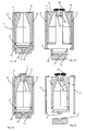
- Fig. 1 shows a rough schematic representation of a blowing station 2.
- This blowing station 2 has here a designated in its entirety by 4 blow mold.
- This blow mold carrier has two carrier halves 22 and 24, which in operation the blow mold take up.
- the blow mold 6 is also composed of two blow moldings or blow mold halves 12 and 14, wherein the first blow mold half 12 is fixed to a first carrier half 22 and a second blow mold half 14 on a second carrier half 24.
- a corresponding fastening mechanism is in Fig. 1 but not shown.
- blow mold 6 still has a bottom part 16, which forms a cavity 15 together with the two blow mold parts 12 and 14, are expanded within the (not shown) plastic preforms to the containers.
- the reference numeral 36 refers to a feed element, which brings the bottom part 16 in a working operation on the two side parts 12 and 14 of the blow mold.
- the reference numeral 30 roughly shows a fastening device which secures the two blow mold halves for removal of the blow mold in a closed state to each other.
- These may be, for example, oppositely polarized magnets which hold the two blow mold halves together.
- one of the two magnets could be displaceable relative to the other in a longitudinal direction L of the blow mold, so that no magnetic force is produced between the two blow mold parts 12 and 14 during operation.
- one or both magnets it would also be possible for one or both magnets to be displaced inwards in the radial direction R of the blow mold so that likewise a magnetic force during operation between the two blow mold parts 12 and 14 is minimized or reduced to zero.
- a multiplicity of alternately polarized magnets to be arranged in the longitudinal direction L in one of the two blow mold halves, and furthermore a sliding element is provided which has magnetizable surfaces corresponding to the pitch of these magnets, this element being displaceable in the direction L. the magnet is. Depending on the position of this displacement element, the surfaces either cover the magnets so that the magnetic force is mediated or stand between these magnets so that the magnets are short-circuited and in this way the magnetic force is considerably reduced.
- the fastening device is thus composed here of at least two magnets 31, 32 together, wherein the magnet 31 on the first Blasformhquest 12 and the other magnet the second blow mold half 14 is arranged.
- the two blow mold halves could have recesses in which the two magnets 31, 32 are arranged.
- only a magnet could be provided which attracts a magnetic portion of the other blow mold half.
- the magnets could also be displaceable in a longitudinal direction L of the blow mold in order to release the magnetic hold.
- the blow mold carrier 4 is first released from the blow mold 6 and then the blow mold can be removed from the machine in its entirety. However, it would also be a removal in the longitudinal direction. perpendicular to the plane of the figure possible.
- FIG. 2 shows a further illustration of a blowing station according to the invention. Again, a state is shown in which the blow mold carrier 22 and 24 are partially open and the blow mold itself is arranged in a closed state. In this state, the blow mold in the closed state along the arrow P2 from the blow mold, whose two side parts 22 and 24 are pivoted along the arrows P1 to the outside, can be removed.
- the device and the handling be designed such that changeover time is saved.
- This time saving results mainly from the common removal or insertion of the Blow mold that is, the two mold halves 12 and 14 and the bottom mold 16 so that only one process instead of three different processes are necessary as in the prior art.
- blow mold is stored together and not stored as before, the individual components of the blow mold. Due to this common storage less storage space is required on the one hand, but on the other hand, the associated mold parts 12, 14 and 16 can be found quickly.
- the two mold halves 12, 14 are unlocked from this mold carrier 4 when the mold carrier is closed. This is, as mentioned, a change to today's approach. Only when the two mold halves are unlocked from the mold carrier, the two mold carriers 22 and 24 are opened, wherein this opening can be done both manually and automatically.
- the two blow mold halves 12 and 14 remain together, wherein, as mentioned, in addition to the magnetic connection, for example, a snap connection can come into question.
- the mold carriers 22 and 24 have then removed so far from the mold halves 12 and 14 that the mold halves together on the bottom mold 16 (see. Fig. 1 ) are free.
- the mold halves 12 and 14 are advantageous to the bottom mold 16 to each other around the circumference and also axially fixed to ensure a positionally accurate reinsertion.
- the so-related shape change parts 12, 14 and 16 are free to remove and can be removed and stored manually or fully automatically.
- the contiguous mold change parts 12, 14 and 16 can be used. Subsequently, the bottom mold is positioned with the mold halves 12 and 14 fixed thereon, and in a next step, the two mold carriers 22 and 24 can close. Only in a final step turn the blow mold halves 12 and 14 are locked with the respective carrier halves 22 and 24 to put the change in a working condition.
- the reference numeral 25 roughly schematically illustrates a connection mechanism through which the support members 22, 24 with the blow mold 6, and their blow mold halves are in communication.
- this is an automatically releasable connection mechanism, which can be solved or closed, for example via a guide curve.
- This connection mechanism preferably has a plurality of holding elements with which the blow-molded parts are held on the carrier parts 22, 24. Also, this connection mechanism could have magnetic holding elements.
- the connection between the blow mold and the support parts could also be generated by a negative pressure.
- coolant connections can also be applied to the blow mold 6 in order to supply them with a particular liquid temperature control medium or generally with a temperature control agent. These connections could also be automatically detachable or connectable.
- the Fig. 3a - 3d show different stations for removing a blow mold.
- a closed mold carrier 4 with a blow mold 6 inserted therein is shown in a production mode. More precisely, here the two blow moldings 12 and 14 are fixedly arranged on the corresponding carrier parts 22 and 24 so that, when the two carrier halves 22 and 24 unfold, the blow mold parts 12 and 14 are also moved.
- the reference numeral 17 denotes an engagement region with which, when the two blow-molded parts 12 and 14 are folded, a bottom part 16 is also hooked.
- the bottom part 16 can be brought to the two mold parts 12 and 14 via a feed mechanism 19 wherein this feed mechanism 19 has a recess 21, which in turn engages a correspondingly adapted projection 23 of the bottom part 16.
- Fig. 3b shows an opened state of the two blow mold carrier 22 and 24 with the therein locked blow moldings 12 and 14.
- the reference numeral 13 refers to an engagement region by means of which the blow mold parts 12 and 14 are respectively locked to the blow mold carriers 12 and 14.
- a holding element 40 can be introduced into the interior of the blow mold 6, wherein this holding element is used in particular for transporting the blow mold 6.
- This holding element has an engagement portion 42, whose cross-section is larger than an opening cross-section of the blow mold 6 in the closed state.
- Fig. 3c shows that the retaining element 40 can not be removed from the blow mold 6 due to its configuration or the engagement region 42. Rather, the blow mold 6 can be transported with the aid of this holding element.
- the carrier was as in Fig. 2 illustrated, opened so that now the blow mold 6 can be removed together with the mold parts 12 and 14 and the bottom part 16 by means of the holding member 40.
- the holding element recesses 44 see. Fig. 3c ), in which a gripping device or gripping clip 28 can engage, which also serves to transport the containers during normal operation of the system.
- This gripping device can remove the blow mold (if necessary also via the transport paths usual in normal operation), for example to a magazine.
- the blow mold can also be transported to a cleaning station in which a possibly. Automatic cleaning of the blow mold is possible.
- the individual movements which serve for introducing the retaining element 40 or also for transporting the blow mold can be derived from a movement out of a normal working operation of the system.
- the holding piece or the dummy with the mold halves 12 and 14 and the bottom mold 16 is inserted in a preoriented manner onto an inlet star.
- the blow mold 6 can be oriented in an input and rotated at a predetermined angle, for example, 20 degrees introduced into the mold carrier 4.
- the holding piece is at least temporarily rotationally connected to the blow mold.
- the holding piece is advantageously rotated, for example via a toothed rack, until the blow-molded parts 12 and 14 and the bottom part 16 engage in the blow mold carrier.
- the water connections for the blow-molded parts and the bottom part 16 can preferably be locked cam-controlled.
- the blow mold 6 can be opened and the holding piece 40 are removed, for example via an outlet star.
- the holding element assumes the task of receiving the two mold halves 12 and 14 and the bottom so that the entire blow mold 6 or at least both blow mold halves 12 and 14 can be removed from the open mold carrier 4 at a time.
- this is entered into the closing mold via a transfer arm, which may even be the infeed star of the machine here.
- a transfer arm which may even be the infeed star of the machine here.
- the blow molds 6 are released from the blow mold carrier 4. This can, as mentioned above, for example, be done by a cam-controlled locking.
- any existing water connections can be decoupled via curves.
- blow mold halves 12 and 14 locked on the holding element 40 remain closed and the holding element can be removed together with the blow mold 6, for example with a transfer arm, wherein this transfer arm can also be the outflow star of a system. Subsequently, the entire blow mold 6 can be hung together with the holding element 40 on this holding element in a magazine.
- FIGS. 4a-4c show a further embodiment of a holding piece 60, which engages the blow mold from the outside.
- the holding piece 60 could be moved in the form of a plastic clip with an inlet star in an open mold.
- This holding piece has a multiplicity of holding webs 64 or clips extending in the radial direction of the blow mold. These holding webs are each arranged on a base body 68.
- This base body has on the one hand a circumferential groove 66, in which a gripping clip can engage.
- the base body may also have an opening, so that other gripping elements, such as holding thorns can engage in it.
- Reference numeral 64a refers to holding hooks formed in an outer periphery of the blow moldings 12, 14 engage, for which purpose the blow mold may for example have a circumferential groove.
- the holding piece and lower support ribs 72 which are arranged with the blow mold closed inside it and are supported against the inner wall 7 of the blow mold 6.
- clips or their hooks 64a can grip over the mold, preventing stripping of the fuse by the inner arms or support webs, which bear against the bottle contour, for example, and thus pull the holding element 60 downwards. Dismantling is possible by pulling up or lifting the said clips.
- Fig. 5 illustrates the method according to the invention.
- the reference numeral 52 denotes a heater for heating the preforms
- the reference numeral 54 an inlet star
- the reference numeral 56 a blowing wheel on which a plurality of blowing stations of in Fig. 1 shown type can be arranged
- the reference numeral 58 an outlet star.
- the holding element as explained above, be plugged and snap in a position B, already on the blowing wheel of this holding element in the blow mold 6.
- the water connections can be decoupled and the area D of the blow mold 6 can be unlocked from the blow mold carrier 4.
- a region E it would be possible to remove the holding element 40 together with the blow mold.
- a holding element with a pre-oriented shape can be attached.
- an orientation of the shape can take place.
- the mold can be fixed on a carrier, in a region D the water connections are coupled and a region E with the carrier open, the holding element 40 are removed.
- the exact orientation of the blow mold can be done while closing the mold carrier halves. For example, such an orientation over lugs on the mold carrier 4 is possible.
- the mold is closed, both the water connections are coupled and the mold is fixed in mold carrier 4, whereby, as mentioned above, this can also take place via delivered curves.
- the holding element 40 is disengaged and removed via an outlet star 58.
Landscapes
- Engineering & Computer Science (AREA)
- Mechanical Engineering (AREA)
- Chemical & Material Sciences (AREA)
- Manufacturing & Machinery (AREA)
- Chemical Kinetics & Catalysis (AREA)
- Electrochemistry (AREA)
- Materials Engineering (AREA)
- Metallurgy (AREA)
- Organic Chemistry (AREA)
- Blow-Moulding Or Thermoforming Of Plastics Or The Like (AREA)
- Moulds For Moulding Plastics Or The Like (AREA)
Priority Applications (1)
| Application Number | Priority Date | Filing Date | Title |
|---|---|---|---|
| EP13192285.8A EP2698239B1 (fr) | 2009-09-02 | 2010-08-31 | Procédé et dispositif de montage et/ou de démontage de moules de soufflage |
Applications Claiming Priority (1)
| Application Number | Priority Date | Filing Date | Title |
|---|---|---|---|
| DE102009039695.0A DE102009039695B4 (de) | 2009-09-02 | 2009-09-02 | Verfahren und Vorrichtung zur Montage und/oder Demontage von Blasformen |
Related Child Applications (2)
| Application Number | Title | Priority Date | Filing Date |
|---|---|---|---|
| EP13192285.8A Division EP2698239B1 (fr) | 2009-09-02 | 2010-08-31 | Procédé et dispositif de montage et/ou de démontage de moules de soufflage |
| EP13192285.8A Division-Into EP2698239B1 (fr) | 2009-09-02 | 2010-08-31 | Procédé et dispositif de montage et/ou de démontage de moules de soufflage |
Publications (2)
| Publication Number | Publication Date |
|---|---|
| EP2292403A1 true EP2292403A1 (fr) | 2011-03-09 |
| EP2292403B1 EP2292403B1 (fr) | 2014-04-16 |
Family
ID=43383460
Family Applications (2)
| Application Number | Title | Priority Date | Filing Date |
|---|---|---|---|
| EP10174578.4A Active EP2292403B1 (fr) | 2009-09-02 | 2010-08-31 | Procédé et dispositif de démontage de moules de soufflage |
| EP13192285.8A Active EP2698239B1 (fr) | 2009-09-02 | 2010-08-31 | Procédé et dispositif de montage et/ou de démontage de moules de soufflage |
Family Applications After (1)
| Application Number | Title | Priority Date | Filing Date |
|---|---|---|---|
| EP13192285.8A Active EP2698239B1 (fr) | 2009-09-02 | 2010-08-31 | Procédé et dispositif de montage et/ou de démontage de moules de soufflage |
Country Status (4)
| Country | Link |
|---|---|
| US (1) | US8920151B2 (fr) |
| EP (2) | EP2292403B1 (fr) |
| CN (2) | CN102001179A (fr) |
| DE (2) | DE202009018781U1 (fr) |
Cited By (2)
| Publication number | Priority date | Publication date | Assignee | Title |
|---|---|---|---|---|
| EP2570251A3 (fr) * | 2011-09-13 | 2014-10-08 | Krones AG | Souffleuse avec stations de soufflage démontables |
| EP2979842A4 (fr) * | 2013-03-27 | 2016-12-07 | Dainippon Printing Co Ltd | Matrice de moulage par soufflage de bouteille en matière plastique |
Families Citing this family (13)
| Publication number | Priority date | Publication date | Assignee | Title |
|---|---|---|---|---|
| FR2943576B1 (fr) * | 2009-03-30 | 2011-03-18 | Saint Gobain | Procede de moulage d' une piece en matiere plastique avec une piece rapportee metallique maintenue par aimantation, dispositif de moulage et utilisation d'un aimant pour la fixation de ladite piece |
| DE102009050637B4 (de) | 2009-05-06 | 2019-06-19 | Krones Aktiengesellschaft | Blasformanordnung |
| DE102009035871A1 (de) | 2009-07-31 | 2011-02-03 | Krones Ag | Schnellwechselmechansimus für Bodenteile |
| FR2949703A1 (fr) * | 2009-09-07 | 2011-03-11 | Sidel Participations | Dispositif de moulage equipe de moyens de fixation d'un demi-moule par attaction contre le fond d'un logement associe d'un porte-moule |
| MX2012002242A (es) * | 2009-09-07 | 2012-04-11 | Sidel Participations | Metodo para cambiar un molde. |
| FR2972386B1 (fr) | 2011-03-08 | 2014-10-10 | Sidel Participations | Systeme d'assistance au changement de moule d'unite de moulage d'une machine de fabrication de recipients |
| ITUB20160870A1 (it) * | 2016-02-19 | 2017-08-19 | Sipa Progettazione Automaz | Stampo di soffiaggio |
| CN109661611B (zh) * | 2016-10-10 | 2021-12-21 | 金泰克斯公司 | 偏振窗组合件 |
| WO2019025549A1 (fr) | 2017-08-02 | 2019-02-07 | Krones Ag | Processus de changement de moules de soufflage à l'aide d'un dispositif de changement |
| DE102017120774A1 (de) | 2017-09-08 | 2019-03-14 | Krones Ag | Vorrichtung und Verfahren zum Umformen von Kunststoffvorformlingen zu Kunststoffbehältnissen mit Wechselroboter |
| JPWO2023182427A1 (fr) * | 2022-03-25 | 2023-09-28 | ||
| CN114905725B (zh) * | 2022-06-01 | 2023-11-17 | 湖南远超环保科技有限公司 | 一种自动吹瓶机快速换模装置 |
| CN115923093B (zh) * | 2022-11-16 | 2023-11-03 | 佛山市南海功成塑料有限公司 | 一种塑料瓶吹塑成型生产设备和塑料瓶吹塑成型方法 |
Citations (5)
| Publication number | Priority date | Publication date | Assignee | Title |
|---|---|---|---|---|
| DE3613543C1 (de) * | 1986-04-22 | 1986-12-18 | Fried. Krupp Gmbh, 4300 Essen | Schnellspanneinheit für eine Blasform |
| JPH10180813A (ja) * | 1996-12-26 | 1998-07-07 | Sekisui Chem Co Ltd | 射出成形用金型 |
| EP0893221A2 (fr) * | 1997-07-23 | 1999-01-27 | Edegs Formenbau GmbH | Moule pour le moulage par injection ou compression |
| WO2006113428A2 (fr) * | 2005-04-15 | 2006-10-26 | Graham Packaging Company, L.P. | Systeme et procede de fabrication de contenants moules-souffles presentant une repartition du plastique optimale |
| AT9438U1 (de) * | 2006-07-14 | 2007-10-15 | Engel Austria Gmbh | Schliesseinheit einer spritzgiessmaschine |
Family Cites Families (13)
| Publication number | Priority date | Publication date | Assignee | Title |
|---|---|---|---|---|
| US2348347A (en) * | 1942-09-05 | 1944-05-09 | Hartford Empire Co | Paste mold machine for forming hollow glass blanks into finally blown articles |
| US2756885A (en) * | 1954-06-11 | 1956-07-31 | Elwell Parker Electric Co | Die handling industrial lift truck |
| US2925929A (en) * | 1955-12-30 | 1960-02-23 | Rack Specialists Inc | Die handler |
| US3912435A (en) * | 1974-05-06 | 1975-10-14 | Ethyl Dev Corp | Blow molding apparatus |
| US5229143A (en) * | 1990-08-16 | 1993-07-20 | Kao Corporation | Molding machine |
| DE69125720T2 (de) * | 1991-12-28 | 1997-10-23 | Kurata Kk | Vorrichtung zum Wechseln von Werkzeugen bei Blasformmaschinen |
| DE29619781U1 (de) * | 1996-11-15 | 1997-01-02 | Mauser-Werke GmbH, 50321 Brühl | Blasformmaschine |
| US6655268B2 (en) * | 2001-10-31 | 2003-12-02 | The Boeing Company | Compact hot press |
| DE102004057102B4 (de) * | 2004-11-26 | 2021-01-14 | Krones Aktiengesellschaft | Formblasmaschine |
| DE102005035233A1 (de) * | 2005-07-25 | 2007-04-12 | Sig Technology Ag | Vorrichtung zur Halterung von Blasformsegmenten |
| US20070269545A1 (en) * | 2006-05-16 | 2007-11-22 | Graham Packaging Company, L.P. | Magnetic quick change mold |
| DE102008004773B4 (de) * | 2008-01-16 | 2022-03-10 | Krones Aktiengesellschaft | Verfahren zum Umrüsten einer Blasmaschine |
| DE102009039700A1 (de) * | 2009-09-02 | 2011-03-10 | Krones Ag | Magazinvorrichtung zur Aufbewahrung von Blasformen |
-
2009
- 2009-09-02 DE DE202009018781U patent/DE202009018781U1/de not_active Expired - Lifetime
- 2009-09-02 DE DE102009039695.0A patent/DE102009039695B4/de active Active
-
2010
- 2010-08-30 US US12/871,144 patent/US8920151B2/en active Active
- 2010-08-30 CN CN2010102789856A patent/CN102001179A/zh active Pending
- 2010-08-30 CN CN201810939688.8A patent/CN109130143A/zh active Pending
- 2010-08-31 EP EP10174578.4A patent/EP2292403B1/fr active Active
- 2010-08-31 EP EP13192285.8A patent/EP2698239B1/fr active Active
Patent Citations (5)
| Publication number | Priority date | Publication date | Assignee | Title |
|---|---|---|---|---|
| DE3613543C1 (de) * | 1986-04-22 | 1986-12-18 | Fried. Krupp Gmbh, 4300 Essen | Schnellspanneinheit für eine Blasform |
| JPH10180813A (ja) * | 1996-12-26 | 1998-07-07 | Sekisui Chem Co Ltd | 射出成形用金型 |
| EP0893221A2 (fr) * | 1997-07-23 | 1999-01-27 | Edegs Formenbau GmbH | Moule pour le moulage par injection ou compression |
| WO2006113428A2 (fr) * | 2005-04-15 | 2006-10-26 | Graham Packaging Company, L.P. | Systeme et procede de fabrication de contenants moules-souffles presentant une repartition du plastique optimale |
| AT9438U1 (de) * | 2006-07-14 | 2007-10-15 | Engel Austria Gmbh | Schliesseinheit einer spritzgiessmaschine |
Cited By (4)
| Publication number | Priority date | Publication date | Assignee | Title |
|---|---|---|---|---|
| EP2570251A3 (fr) * | 2011-09-13 | 2014-10-08 | Krones AG | Souffleuse avec stations de soufflage démontables |
| EP2979842A4 (fr) * | 2013-03-27 | 2016-12-07 | Dainippon Printing Co Ltd | Matrice de moulage par soufflage de bouteille en matière plastique |
| US9573316B2 (en) | 2013-03-27 | 2017-02-21 | Dai Nippon Printing Co., Ltd. | Blow molding mold for plastic bottle |
| EP2979842B1 (fr) | 2013-03-27 | 2018-07-25 | Dai Nippon Printing Co., Ltd. | Matrice de moulage par soufflage de bouteille en matière plastique |
Also Published As
| Publication number | Publication date |
|---|---|
| CN109130143A (zh) | 2019-01-04 |
| EP2698239B1 (fr) | 2016-08-31 |
| DE202009018781U1 (de) | 2013-07-08 |
| DE102009039695B4 (de) | 2020-08-13 |
| EP2292403B1 (fr) | 2014-04-16 |
| EP2698239A1 (fr) | 2014-02-19 |
| US8920151B2 (en) | 2014-12-30 |
| DE102009039695A1 (de) | 2011-03-17 |
| CN102001179A (zh) | 2011-04-06 |
| US20110057342A1 (en) | 2011-03-10 |
Similar Documents
| Publication | Publication Date | Title |
|---|---|---|
| EP2292403B1 (fr) | Procédé et dispositif de démontage de moules de soufflage | |
| EP2292405B1 (fr) | Procédé et dispositif de montage et/ou de démontage de moules de soufflage | |
| DE112006001802B4 (de) | Vorrichtung zur Herstellung von Blasformsegmenten | |
| DE202012013696U1 (de) | System zur Unterstützung des Formwechsels einer Formungseinheit einer Behälterherstellungsmaschine | |
| EP2937203B1 (fr) | Machine et procédé formage par soufflage avec accouplement de sol et/ou côté automatique | |
| DE102014103159A1 (de) | Vorrichtung und Verfahren zum Umformen von Kunststoffvorformlingen zu Kunststoffbehältnissen mit automatischer Wechseleinrichtung für Garniturenteile | |
| DE102015117292A1 (de) | Blasformmaschine mit automatisch betätigbarer Bodenankopplung | |
| DE102011116192A1 (de) | Verfahren und Vorrichtung zur Blasformung von Behältern | |
| DE10354506A1 (de) | Vorrichtung zur Blasformung von Behältern | |
| EP3294521B1 (fr) | Dispositif de moulage par soufflage présentant un accouplement de fond à actionnement automatique et procédé pour le fonctionnement du dispositif associé | |
| EP3678827A1 (fr) | Dispositif et procédé de transformation de préformes en matière plastique en récipients en matière plastique au moyen d'un robot de changement | |
| WO2023174805A1 (fr) | Machine de formage pour la mise en forme de préformes en récipients et procédé de fonctionnement d'une telle machine | |
| DE102013109910A1 (de) | Vorrichtung zum Wechsel von Spritzgussformen | |
| DE102008049906A1 (de) | Streckblasmaschine mit für unterschiedliche Behältnisse verwendbarer Reckstange | |
| EP3619018B1 (fr) | Procédé servant à faire fonctionner un dispositif servant à façonner des préformes en matière plastique en des récipients en matière plastique, et dispositif | |
| DE102015117273A1 (de) | Blasformmaschine mit automatisch betätigbarer Bodenankopplung | |
| EP1048435A1 (fr) | Procédé et appareil de moulage par injection-soufflage | |
| EP4063101A1 (fr) | Moule de soufflage ajustable | |
| EP2349677A1 (fr) | Système de changement rapide pour barres d'étirage | |
| WO2025124825A1 (fr) | Dispositif et système de maintien d'un segment d'outil de moulage, dispositif de manipulation destiné à un segment d'outil de moulage, et procédé de changement d'un segment d'outil de moulage | |
| EP4695071A1 (fr) | Dispositif de moulage par extrusion-soufflage et procédé de fabrication d'une pièce moulée par soufflage | |
| WO2012055736A1 (fr) | Outil de moulage par injection et procédé de fabrication de pièces moulées multicomposantes | |
| WO2017148469A1 (fr) | Moule de coulée et procédé de positionnement et de démoulage d'un noyau métallique à l'intérieur du moule de coulée. |
Legal Events
| Date | Code | Title | Description |
|---|---|---|---|
| PUAI | Public reference made under article 153(3) epc to a published international application that has entered the european phase |
Free format text: ORIGINAL CODE: 0009012 |
|
| AK | Designated contracting states |
Kind code of ref document: A1 Designated state(s): AL AT BE BG CH CY CZ DE DK EE ES FI FR GB GR HR HU IE IS IT LI LT LU LV MC MK MT NL NO PL PT RO SE SI SK SM TR |
|
| AX | Request for extension of the european patent |
Extension state: BA ME RS |
|
| 17P | Request for examination filed |
Effective date: 20110404 |
|
| 17Q | First examination report despatched |
Effective date: 20121029 |
|
| GRAP | Despatch of communication of intention to grant a patent |
Free format text: ORIGINAL CODE: EPIDOSNIGR1 |
|
| RIC1 | Information provided on ipc code assigned before grant |
Ipc: B29C 49/06 20060101ALN20130613BHEP Ipc: B29C 49/48 20060101AFI20130613BHEP |
|
| INTG | Intention to grant announced |
Effective date: 20130709 |
|
| GRAS | Grant fee paid |
Free format text: ORIGINAL CODE: EPIDOSNIGR3 |
|
| GRAP | Despatch of communication of intention to grant a patent |
Free format text: ORIGINAL CODE: EPIDOSNIGR1 |
|
| RIC1 | Information provided on ipc code assigned before grant |
Ipc: B29C 49/48 20060101AFI20131128BHEP Ipc: B29C 49/06 20060101ALN20131128BHEP |
|
| INTG | Intention to grant announced |
Effective date: 20131211 |
|
| GRAA | (expected) grant |
Free format text: ORIGINAL CODE: 0009210 |
|
| AK | Designated contracting states |
Kind code of ref document: B1 Designated state(s): AL AT BE BG CH CY CZ DE DK EE ES FI FR GB GR HR HU IE IS IT LI LT LU LV MC MK MT NL NO PL PT RO SE SI SK SM TR |
|
| REG | Reference to a national code |
Ref country code: GB Ref legal event code: FG4D Free format text: NOT ENGLISH |
|
| REG | Reference to a national code |
Ref country code: CH Ref legal event code: EP |
|
| REG | Reference to a national code |
Ref country code: AT Ref legal event code: REF Ref document number: 662235 Country of ref document: AT Kind code of ref document: T Effective date: 20140515 |
|
| REG | Reference to a national code |
Ref country code: IE Ref legal event code: FG4D Free format text: LANGUAGE OF EP DOCUMENT: GERMAN |
|
| REG | Reference to a national code |
Ref country code: DE Ref legal event code: R096 Ref document number: 502010006654 Country of ref document: DE Effective date: 20140528 |
|
| REG | Reference to a national code |
Ref country code: NL Ref legal event code: VDEP Effective date: 20140416 |
|
| REG | Reference to a national code |
Ref country code: LT Ref legal event code: MG4D |
|
| PG25 | Lapsed in a contracting state [announced via postgrant information from national office to epo] |
Ref country code: GR Free format text: LAPSE BECAUSE OF FAILURE TO SUBMIT A TRANSLATION OF THE DESCRIPTION OR TO PAY THE FEE WITHIN THE PRESCRIBED TIME-LIMIT Effective date: 20140717 Ref country code: LT Free format text: LAPSE BECAUSE OF FAILURE TO SUBMIT A TRANSLATION OF THE DESCRIPTION OR TO PAY THE FEE WITHIN THE PRESCRIBED TIME-LIMIT Effective date: 20140416 Ref country code: NO Free format text: LAPSE BECAUSE OF FAILURE TO SUBMIT A TRANSLATION OF THE DESCRIPTION OR TO PAY THE FEE WITHIN THE PRESCRIBED TIME-LIMIT Effective date: 20140716 Ref country code: FI Free format text: LAPSE BECAUSE OF FAILURE TO SUBMIT A TRANSLATION OF THE DESCRIPTION OR TO PAY THE FEE WITHIN THE PRESCRIBED TIME-LIMIT Effective date: 20140416 Ref country code: BG Free format text: LAPSE BECAUSE OF FAILURE TO SUBMIT A TRANSLATION OF THE DESCRIPTION OR TO PAY THE FEE WITHIN THE PRESCRIBED TIME-LIMIT Effective date: 20140716 Ref country code: NL Free format text: LAPSE BECAUSE OF FAILURE TO SUBMIT A TRANSLATION OF THE DESCRIPTION OR TO PAY THE FEE WITHIN THE PRESCRIBED TIME-LIMIT Effective date: 20140416 Ref country code: CY Free format text: LAPSE BECAUSE OF FAILURE TO SUBMIT A TRANSLATION OF THE DESCRIPTION OR TO PAY THE FEE WITHIN THE PRESCRIBED TIME-LIMIT Effective date: 20140416 Ref country code: IS Free format text: LAPSE BECAUSE OF FAILURE TO SUBMIT A TRANSLATION OF THE DESCRIPTION OR TO PAY THE FEE WITHIN THE PRESCRIBED TIME-LIMIT Effective date: 20140816 |
|
| PG25 | Lapsed in a contracting state [announced via postgrant information from national office to epo] |
Ref country code: PL Free format text: LAPSE BECAUSE OF FAILURE TO SUBMIT A TRANSLATION OF THE DESCRIPTION OR TO PAY THE FEE WITHIN THE PRESCRIBED TIME-LIMIT Effective date: 20140416 Ref country code: HR Free format text: LAPSE BECAUSE OF FAILURE TO SUBMIT A TRANSLATION OF THE DESCRIPTION OR TO PAY THE FEE WITHIN THE PRESCRIBED TIME-LIMIT Effective date: 20140416 Ref country code: SE Free format text: LAPSE BECAUSE OF FAILURE TO SUBMIT A TRANSLATION OF THE DESCRIPTION OR TO PAY THE FEE WITHIN THE PRESCRIBED TIME-LIMIT Effective date: 20140416 Ref country code: LV Free format text: LAPSE BECAUSE OF FAILURE TO SUBMIT A TRANSLATION OF THE DESCRIPTION OR TO PAY THE FEE WITHIN THE PRESCRIBED TIME-LIMIT Effective date: 20140416 Ref country code: ES Free format text: LAPSE BECAUSE OF FAILURE TO SUBMIT A TRANSLATION OF THE DESCRIPTION OR TO PAY THE FEE WITHIN THE PRESCRIBED TIME-LIMIT Effective date: 20140416 |
|
| PG25 | Lapsed in a contracting state [announced via postgrant information from national office to epo] |
Ref country code: PT Free format text: LAPSE BECAUSE OF FAILURE TO SUBMIT A TRANSLATION OF THE DESCRIPTION OR TO PAY THE FEE WITHIN THE PRESCRIBED TIME-LIMIT Effective date: 20140818 |
|
| REG | Reference to a national code |
Ref country code: DE Ref legal event code: R097 Ref document number: 502010006654 Country of ref document: DE |
|
| PG25 | Lapsed in a contracting state [announced via postgrant information from national office to epo] |
Ref country code: SK Free format text: LAPSE BECAUSE OF FAILURE TO SUBMIT A TRANSLATION OF THE DESCRIPTION OR TO PAY THE FEE WITHIN THE PRESCRIBED TIME-LIMIT Effective date: 20140416 Ref country code: DK Free format text: LAPSE BECAUSE OF FAILURE TO SUBMIT A TRANSLATION OF THE DESCRIPTION OR TO PAY THE FEE WITHIN THE PRESCRIBED TIME-LIMIT Effective date: 20140416 Ref country code: CZ Free format text: LAPSE BECAUSE OF FAILURE TO SUBMIT A TRANSLATION OF THE DESCRIPTION OR TO PAY THE FEE WITHIN THE PRESCRIBED TIME-LIMIT Effective date: 20140416 Ref country code: EE Free format text: LAPSE BECAUSE OF FAILURE TO SUBMIT A TRANSLATION OF THE DESCRIPTION OR TO PAY THE FEE WITHIN THE PRESCRIBED TIME-LIMIT Effective date: 20140416 Ref country code: RO Free format text: LAPSE BECAUSE OF FAILURE TO SUBMIT A TRANSLATION OF THE DESCRIPTION OR TO PAY THE FEE WITHIN THE PRESCRIBED TIME-LIMIT Effective date: 20140416 |
|
| PLBE | No opposition filed within time limit |
Free format text: ORIGINAL CODE: 0009261 |
|
| STAA | Information on the status of an ep patent application or granted ep patent |
Free format text: STATUS: NO OPPOSITION FILED WITHIN TIME LIMIT |
|
| 26N | No opposition filed |
Effective date: 20150119 |
|
| PG25 | Lapsed in a contracting state [announced via postgrant information from national office to epo] |
Ref country code: MC Free format text: LAPSE BECAUSE OF FAILURE TO SUBMIT A TRANSLATION OF THE DESCRIPTION OR TO PAY THE FEE WITHIN THE PRESCRIBED TIME-LIMIT Effective date: 20140416 Ref country code: LU Free format text: LAPSE BECAUSE OF FAILURE TO SUBMIT A TRANSLATION OF THE DESCRIPTION OR TO PAY THE FEE WITHIN THE PRESCRIBED TIME-LIMIT Effective date: 20140831 |
|
| REG | Reference to a national code |
Ref country code: CH Ref legal event code: PL |
|
| GBPC | Gb: european patent ceased through non-payment of renewal fee |
Effective date: 20140831 |
|
| PG25 | Lapsed in a contracting state [announced via postgrant information from national office to epo] |
Ref country code: LI Free format text: LAPSE BECAUSE OF NON-PAYMENT OF DUE FEES Effective date: 20140831 Ref country code: CH Free format text: LAPSE BECAUSE OF NON-PAYMENT OF DUE FEES Effective date: 20140831 Ref country code: BE Free format text: LAPSE BECAUSE OF NON-PAYMENT OF DUE FEES Effective date: 20140831 |
|
| REG | Reference to a national code |
Ref country code: DE Ref legal event code: R097 Ref document number: 502010006654 Country of ref document: DE Effective date: 20150119 |
|
| REG | Reference to a national code |
Ref country code: IE Ref legal event code: MM4A |
|
| PG25 | Lapsed in a contracting state [announced via postgrant information from national office to epo] |
Ref country code: SI Free format text: LAPSE BECAUSE OF FAILURE TO SUBMIT A TRANSLATION OF THE DESCRIPTION OR TO PAY THE FEE WITHIN THE PRESCRIBED TIME-LIMIT Effective date: 20140416 Ref country code: GB Free format text: LAPSE BECAUSE OF NON-PAYMENT OF DUE FEES Effective date: 20140831 |
|
| PG25 | Lapsed in a contracting state [announced via postgrant information from national office to epo] |
Ref country code: IE Free format text: LAPSE BECAUSE OF NON-PAYMENT OF DUE FEES Effective date: 20140831 |
|
| PG25 | Lapsed in a contracting state [announced via postgrant information from national office to epo] |
Ref country code: SM Free format text: LAPSE BECAUSE OF FAILURE TO SUBMIT A TRANSLATION OF THE DESCRIPTION OR TO PAY THE FEE WITHIN THE PRESCRIBED TIME-LIMIT Effective date: 20140416 |
|
| PG25 | Lapsed in a contracting state [announced via postgrant information from national office to epo] |
Ref country code: MT Free format text: LAPSE BECAUSE OF FAILURE TO SUBMIT A TRANSLATION OF THE DESCRIPTION OR TO PAY THE FEE WITHIN THE PRESCRIBED TIME-LIMIT Effective date: 20140416 |
|
| REG | Reference to a national code |
Ref country code: FR Ref legal event code: PLFP Year of fee payment: 7 |
|
| PG25 | Lapsed in a contracting state [announced via postgrant information from national office to epo] |
Ref country code: HU Free format text: LAPSE BECAUSE OF FAILURE TO SUBMIT A TRANSLATION OF THE DESCRIPTION OR TO PAY THE FEE WITHIN THE PRESCRIBED TIME-LIMIT; INVALID AB INITIO Effective date: 20100831 Ref country code: TR Free format text: LAPSE BECAUSE OF FAILURE TO SUBMIT A TRANSLATION OF THE DESCRIPTION OR TO PAY THE FEE WITHIN THE PRESCRIBED TIME-LIMIT Effective date: 20140416 |
|
| REG | Reference to a national code |
Ref country code: AT Ref legal event code: MM01 Ref document number: 662235 Country of ref document: AT Kind code of ref document: T Effective date: 20150831 |
|
| PG25 | Lapsed in a contracting state [announced via postgrant information from national office to epo] |
Ref country code: AT Free format text: LAPSE BECAUSE OF NON-PAYMENT OF DUE FEES Effective date: 20150831 |
|
| REG | Reference to a national code |
Ref country code: FR Ref legal event code: PLFP Year of fee payment: 8 |
|
| PG25 | Lapsed in a contracting state [announced via postgrant information from national office to epo] |
Ref country code: MK Free format text: LAPSE BECAUSE OF FAILURE TO SUBMIT A TRANSLATION OF THE DESCRIPTION OR TO PAY THE FEE WITHIN THE PRESCRIBED TIME-LIMIT Effective date: 20140416 |
|
| REG | Reference to a national code |
Ref country code: FR Ref legal event code: PLFP Year of fee payment: 9 |
|
| PG25 | Lapsed in a contracting state [announced via postgrant information from national office to epo] |
Ref country code: AL Free format text: LAPSE BECAUSE OF FAILURE TO SUBMIT A TRANSLATION OF THE DESCRIPTION OR TO PAY THE FEE WITHIN THE PRESCRIBED TIME-LIMIT Effective date: 20140416 |
|
| P01 | Opt-out of the competence of the unified patent court (upc) registered |
Effective date: 20230523 |
|
| PGFP | Annual fee paid to national office [announced via postgrant information from national office to epo] |
Ref country code: DE Payment date: 20250702 Year of fee payment: 16 |
|
| PGFP | Annual fee paid to national office [announced via postgrant information from national office to epo] |
Ref country code: IT Payment date: 20250722 Year of fee payment: 16 |
|
| PGFP | Annual fee paid to national office [announced via postgrant information from national office to epo] |
Ref country code: FR Payment date: 20250703 Year of fee payment: 16 |