EP2292512A2 - Siège d'avion doté d'un accoudoir réglable - Google Patents
Siège d'avion doté d'un accoudoir réglable Download PDFInfo
- Publication number
- EP2292512A2 EP2292512A2 EP10172167A EP10172167A EP2292512A2 EP 2292512 A2 EP2292512 A2 EP 2292512A2 EP 10172167 A EP10172167 A EP 10172167A EP 10172167 A EP10172167 A EP 10172167A EP 2292512 A2 EP2292512 A2 EP 2292512A2
- Authority
- EP
- European Patent Office
- Prior art keywords
- arm
- support member
- seat
- arm support
- free end
- Prior art date
- Legal status (The legal status is an assumption and is not a legal conclusion. Google has not performed a legal analysis and makes no representation as to the accuracy of the status listed.)
- Granted
Links
Images
Classifications
-
- B—PERFORMING OPERATIONS; TRANSPORTING
- B64—AIRCRAFT; AVIATION; COSMONAUTICS
- B64C—AEROPLANES; HELICOPTERS
- B64C11/00—Propellers, e.g. of ducted type; Features common to propellers and rotors for rotorcraft
- B64C11/02—Hub construction
- B64C11/04—Blade mountings
- B64C11/06—Blade mountings for variable-pitch blades
- B64C11/065—Blade mountings for variable-pitch blades variable only when stationary
-
- B—PERFORMING OPERATIONS; TRANSPORTING
- B64—AIRCRAFT; AVIATION; COSMONAUTICS
- B64D—EQUIPMENT FOR FITTING IN OR TO AIRCRAFT; FLIGHT SUITS; PARACHUTES; ARRANGEMENT OR MOUNTING OF POWER PLANTS OR PROPULSION TRANSMISSIONS IN AIRCRAFT
- B64D11/00—Passenger or crew accommodation; Flight-deck installations not otherwise provided for
- B64D11/06—Arrangements of seats, or adaptations or details specially adapted for aircraft seats
- B64D11/0646—Seats characterised by special features of stationary arms, foot or head rests
-
- Y—GENERAL TAGGING OF NEW TECHNOLOGICAL DEVELOPMENTS; GENERAL TAGGING OF CROSS-SECTIONAL TECHNOLOGIES SPANNING OVER SEVERAL SECTIONS OF THE IPC; TECHNICAL SUBJECTS COVERED BY FORMER USPC CROSS-REFERENCE ART COLLECTIONS [XRACs] AND DIGESTS
- Y10—TECHNICAL SUBJECTS COVERED BY FORMER USPC
- Y10T—TECHNICAL SUBJECTS COVERED BY FORMER US CLASSIFICATION
- Y10T403/00—Joints and connections
- Y10T403/32—Articulated members
- Y10T403/32254—Lockable at fixed position
- Y10T403/32467—Telescoping members
Definitions
- pilot seating typically require that the pilot seating include an armrest that is adjustable to accommodate multiple operators to position their arm to safely and comfortably operate the side stick controller. Once in this position, the armrest must then be securely locked in its new location.
- Prior art pilot seating has conventionally included an adjustable armrest that is pivoted near the occupant's elbow. The pivot is then movable vertically along the axis of the seat back. This type of armrest is cumbersome to use because must first be adjusted vertically to accommodate the occupant's elbow height, then the angle adjusted so that the occupant's hand is located at the appropriate position relative to the side stick controller.
- a pilot seat having an adjustable armrest that is not constrained to tilt about a pivot fixed at the pilot's elbow, but which freely floats (e.g., can be tilted about an axis through the pilot's wrist or any other location) and can be smoothly and effortlessly locked into position.
- the present invention comprises an aircraft seat with an adjustable armrest.
- the armrest platform is supported by a hinged attachment to an armrest support member.
- the armrest support member rather than the armrest platform is hinged to the seat frame near the seat back.
- the hinged attachment between the armrest platform and the arm support member is located at the wrist-end of the arm support member near the aircraft control stick. This arrangement enables a user to raise and lower, then tilt the armrest from a position near the side stick controller rather than tilting from a pivot near the seat back.
- the armrest platform and the armrest support are locked into position by means of telescoping struts that are controlled at the wrist-end of the arm platform member.
- the telescoping struts can be selectively locked to create triangular and/or quadrilateral trusses that lock the armrest firmly into position and may include springs or other elements to bias the armrest platform up and forward so that the armrest "floats" when the telescoping struts re released.
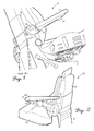
- Fig. 1 is a rear perspective view of a prior art aircraft pilot seat
- Fig. 2 is a rear perspective view of an aircraft seat with adjustable armrest in accordance with features of the present invention
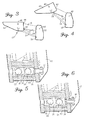
- Fig. 3 is a schematic view of the adjustable armrest of Fig. 1 in its fully lowered and tilted back position;
- Fig. 4 is a schematic view of the adjustable armrest of Fig. 1 in its fully raised and tilted forward position
- Fig. 5 is a cross-sectional view of a locking mechanism to lock the telescoping struts shown in its locked position
- Fig. 6 is a cross-sectional view of a locking mechanism to lock the telescoping struts shown in its unlocked position
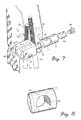
- Fig. 7 is an exploded view of the locking mechanism of Fig. 5 ;
- Fig. 8 is a perspective view of a barrel nut used in the locking mechanism of Fig. 5 .
- FIG. 1 conventional aircraft pilot seating such as prior art seat 10 are often equipped with adjustable armrests such as armrest 12.
- adjustable armrest 12 is adjusted first by releasing lever 14 which enables the pivot 16 to be moved vertically relative to seat back 18 of seat 10.
- This adjustment positions the pivot 16 at a comfortable elevation relative to the pilot's elbow, but may not position armrest 12 so that the pilot's hand is in the proper location for a side stick controller.
- a second adjustment such as thumbwheel 20 must be provided to enable the tilt angle of armrest 12 to be adjusted.
- the tilt angle must be self-locking.
- thumbwheel 20 is often a screw drive mechanism that is slow and cumbersome to operate.
- pivot 16 since pivot 16 is not located exactly at the pilot's elbow, adjustment of the armrest may be a sequential process in which the armrest is iteratively tilted, then raised or lowered and tilted again in order to achieve the proper location.
- an aircraft seat 30 having an adjustable armrest 28 incorporating features of the present invention comprises a seat frame 32 having a seat back portion 34 and a seat pan portion 36.
- An arm support member 38 is attached by means of a hinge 40 to seat frame 32 proximal seat back 34.
- An arm platform member 42 is attached by means of a hinge 46 to the free end 44 of arm support member 38.
- An armrest pad 48 is secured (e.g., with screws) to arm platform member 42. Armrest pad 48 extends from wrist-end 50, which is proximal the side stick controller of the aircraft (not shown) to elbow end 52, which is proximal seat back portion 34.
- Arm support member 38 and arm platform member 42 are preferable made of a lightweight aluminum or titanium alloy but may be constructed of any suitably rigid lightweight material including composites.
- arm platform member 42 is achieved by rotating arm support member 38 about hinge 40, thus raising or lowering arm platform member 42.
- Arm support member 38 can be selectively locked into position by means of a telescoping strut 54 which is attached by a hinge 56 to seat frame 32.
- the free end 58 of telescoping strut 54 telescopes through a locking mechanism 60 described more fully hereinafter.
- Telescoping strut 54, arm support member 38, arm platform member 42 and seat frame 32 form a quadrilateral linkage, and in particular a trapezoidal linkage which, due to the unequal lengths of the linkage arms, forms a rigid truss when telescoping strut 54 is prevented from telescoping through locking mechanism 60.
- the effective length of arm support member 38 is 7-1 ⁇ 2 to 11-1 ⁇ 2 inches, preferably about 9-1 ⁇ 2 inches
- the effective length of arm platform member 42 is 1 to 3 inches, preferably about 2 inches
- the effective length of seat frame 32 is 2 to 6 inches, preferably about 4 inches (but is not the same length as the effective length of arm platform member 42 so as to ensure the linkage cannot form a parallelogram)
- the effective length of telescoping strut 54 varies from about 7-1/2 to about 13-1/2 inches, and preferably varies from about 9-1 ⁇ 2 to 11-1 ⁇ 2 inches depending on the relative positions of arm support member 38 and ann platform member 42.
- effective length means the distance between the attachment points of the frame member in question.
- the effective length of arm support member 38 is the distance from hinge 40 to hinge 46
- the effective length of seat frame 32 is the distance from hinge 40 to hinge 56
- the effective length of telescoping strut 54 is the distance from hinge 56 to locking mechanism 60.
- platform member 42 is achieved by rotating arm platform member 42 about hinge 46.
- Arm platform member 42 can be selectively locked in place about hinge 46 by means of a second telescoping strut 62 which is attached to arm support member 38 by means of a hinge 64.
- the free end 66 of telescoping strut 62 telescopes through locking mechanism 60 in a manner more fully described hereinafter.
- Telescoping strut 62, arm support member 38 and arm platform member 42 form a triangular linkage which becomes a triangular truss that prevents arm platform member from rotating when telescoping strut 62 is prevented from telescoping through locking mechanism 60.
- the effective length of arm support member 38 is 7-1 ⁇ 2 to 11-1 ⁇ 2 inches, preferably about 9-1 ⁇ 2 inches, the effective length of arm platform member 42 is 1 to 3 inches preferably about 2 inches, and the effective length of telescoping strut 62 varies from 4 to 9 inches and preferably varies from about 6 to 7-1 ⁇ 4 inches.
- locking mechanism 60 comprises a pillow block 70 that is secured (e.g., by threaded fasteners) to arm platform member 42.
- Pillow block 70 includes a longitudinal cylindrical bore 72 adapted to receive a pair of pilot sleeves 74, 76 and two transverse bores 92.
- Each of the pilot sleeves 74, 76 has a cylindrical bore adapted to receive a barrel nut 78, 80.
- barrel nut 78 is cross-drilled and threaded with threads 84 matched to threads 86 formed at the end of telescoping strut 62.
- a smooth-walled relief 88 is then formed in barrel nut 78 which enables barrel nut 78 to slide smoothly over threads 86 of telescoping strut 62 as long as barrel nut 78 is biased so relief 88 rather than threads 84 engage the threads 86 of telescoping strut 62.
- the locking mechanism for telescoping strut 62 is assembled by inserting pilot sleeve 74 into pillow block 70 then inserting barrel nut 78 into pilot sleeve 74 so that relief 88 is lined up with aperture 90 formed in pilot sleeve 74.
- Telescoping strut 62 is then passed through the corresponding transverse bores 92 formed in pillow block 70, aperture 90 formed in pilot sleeve 74 and barrel nut 78.
- Aperture 90 in pilot sleeve 74 is sized to approximately the major diameter of threads 86 of telescoping strut 62 so that telescoping strut 62 can slide smoothly through pilot sleeve 74.
- Transverse bore 92 in pillow block 70 is elongated to accommodate the change in angular relationship between telescoping strut 62 and pillow block 70 as armrest 28 is raised, lowered and tilted as described herein.
- locking mechanism 60 can be moved from an unlocked position into a locked position.
- the smooth wall of relief 88 of barrel nut 78 bears against threads 86 of telescoping strut 62 which permits telescoping strut 62 to move smoothly through pillow block 70.
- barrel nut 78 is pressed against telescoping strut 62 so that threads 84 of barrel nut 78 engage threads 86 of telescoping strut 62, which is then pinched between barrel nut 78 and pilot sleeve 74 thus locking telescoping strut 62 firmly into position.
- the use of standard thread forms to fabricate threads 84 of barrel nut 78 and threads 86 of telescoping strut 62 enables production of a very robust locking mechanism, while permitting very precise adjustments at relatively low cost as compared with conventional prior art ratchet and screw drive mechanisms.
- barrel nuts 78 and 80 are urged into their locked position by means of a threaded a locking plunger 94.
- a spring, rubber pad or other resilient means may optionally be included to urge the barrel nuts into their released positions when locking plunger 94 is withdrawn.
- the telescoping struts telescope by passing through a locking mechanism located at the wrist end of the arm support member, the telescoping struts could pass through locks located at the seat back end of the arm support member or could comprise true telescoping struts that lock at a location intermediate the ends of the struts.
- the illustrative embodiment employs standard thread forms, nonstandard thread forms and/or non-helical teeth could be substituted without departing from the scope of the invention.
Landscapes
- Engineering & Computer Science (AREA)
- Aviation & Aerospace Engineering (AREA)
- Chair Legs, Seat Parts, And Backrests (AREA)
- Chairs For Special Purposes, Such As Reclining Chairs (AREA)
- Seats For Vehicles (AREA)
Applications Claiming Priority (1)
| Application Number | Priority Date | Filing Date | Title |
|---|---|---|---|
| US12/552,525 US8146999B2 (en) | 2009-09-02 | 2009-09-02 | Aircraft seat with adjustable armrest |
Publications (3)
| Publication Number | Publication Date |
|---|---|
| EP2292512A2 true EP2292512A2 (fr) | 2011-03-09 |
| EP2292512A3 EP2292512A3 (fr) | 2012-07-04 |
| EP2292512B1 EP2292512B1 (fr) | 2013-12-25 |
Family
ID=43012476
Family Applications (1)
| Application Number | Title | Priority Date | Filing Date |
|---|---|---|---|
| EP10172167.8A Active EP2292512B1 (fr) | 2009-09-02 | 2010-08-06 | Siège d'avion doté d'un accoudoir réglable |
Country Status (3)
| Country | Link |
|---|---|
| US (1) | US8146999B2 (fr) |
| EP (1) | EP2292512B1 (fr) |
| CA (1) | CA2704895C (fr) |
Cited By (2)
| Publication number | Priority date | Publication date | Assignee | Title |
|---|---|---|---|---|
| US9872565B2 (en) | 2012-09-20 | 2018-01-23 | Steelcase Inc. | Chair arm assembly |
| US11304528B2 (en) | 2012-09-20 | 2022-04-19 | Steelcase Inc. | Chair assembly with upholstery covering |
Families Citing this family (19)
| Publication number | Priority date | Publication date | Assignee | Title |
|---|---|---|---|---|
| ITPD20080253A1 (it) * | 2008-08-20 | 2010-02-21 | Clerprem Spa | Bracciolo regolabile in inclinazione, in particolare per autoveicoli |
| US8087729B2 (en) * | 2008-12-09 | 2012-01-03 | Wolfgang K, Llc | Aircraft seat |
| US9714095B2 (en) | 2011-10-07 | 2017-07-25 | Bombardier Inc. | Aircraft seat |
| US9592914B2 (en) | 2011-10-07 | 2017-03-14 | Bombardier Inc. | Aircraft seat |
| US9714862B2 (en) | 2011-10-07 | 2017-07-25 | Bombardier Inc. | Aircraft seat |
| US9073453B2 (en) | 2011-10-07 | 2015-07-07 | Bombardier Inc. | Aircraft seat |
| US9061766B2 (en) | 2011-11-30 | 2015-06-23 | Burkley U. Kladde | Synchronous seat recline mechanism |
| USD750392S1 (en) | 2013-08-20 | 2016-03-01 | Encore Interiors, Inc. | Aircraft seat |
| US9630717B2 (en) | 2013-04-26 | 2017-04-25 | Encore Interiors, Inc. | Aircraft seating assembly with reduced spacing |
| US10583926B2 (en) | 2014-09-25 | 2020-03-10 | Bombardier Inc. | Aircraft seat |
| DE102014118163A1 (de) * | 2014-12-08 | 2016-06-09 | Ferdinand Lusch Gmbh & Co. Kg | Sitzmöbel mit verschwenkbarem Funktionsteil |
| US9844268B2 (en) * | 2015-03-16 | 2017-12-19 | Aaron DeJule | Sitting apparatus |
| US9764844B2 (en) | 2015-04-13 | 2017-09-19 | Encore Seats, Inc. | Aircraft seating assembly |
| US10179650B2 (en) * | 2016-03-10 | 2019-01-15 | B/E Aerospace, Inc. | Sliding seating unit panel for providing enhanced passenger ingress and egress |
| US10144515B2 (en) | 2016-04-01 | 2018-12-04 | Encore Seats, Inc. | Aircraft seating assembly and components |
| US10934002B2 (en) | 2018-01-19 | 2021-03-02 | Ami Industries, Inc. | Aircraft passenger seat extended armrest |
| US10870489B2 (en) * | 2019-05-24 | 2020-12-22 | B/E Aerospace, Inc. | Position adjustable armrest assemblies for passenger seats |
| US11459109B2 (en) | 2020-02-27 | 2022-10-04 | Ami Industries, Inc. | Automatic aircraft pilot seat side-stick armrest |
| US11857085B2 (en) * | 2021-08-31 | 2024-01-02 | Ami Industries, Inc. | Single control console mounted armrest |
Family Cites Families (26)
| Publication number | Priority date | Publication date | Assignee | Title |
|---|---|---|---|---|
| US169027A (en) * | 1875-10-19 | Improvement in joiners clamps | ||
| FR1095113A (fr) * | 1953-10-12 | 1955-05-27 | Aerotherm Corp | Siège avec accoudoir escamotable |
| CH388218A (de) * | 1961-03-29 | 1965-02-15 | Wahli Marcel | Parallelschraubzwinge |
| US4186964A (en) | 1978-10-23 | 1980-02-05 | Fairchild Industries, Inc. | Seat armrest |
| DE7927079U1 (de) | 1979-09-24 | 1980-01-17 | Gebr. Isringhausen, 4920 Lemgo | Sitz mit einer am sitzrahmen angelenkten, neigungsverstellbaren rueckenlehne |
| FR2576281B1 (fr) * | 1985-01-18 | 1992-04-30 | Aerospatiale | Poste de pilotage pourvu d'un manche a balai lateral actionnable par une seule main et siege pour un tel poste de pilotage |
| US5210888A (en) * | 1992-06-25 | 1993-05-18 | Canfield Michael A | Portable tent--cot |
| US5326076A (en) * | 1993-06-07 | 1994-07-05 | Petersen Manufacturing Co. Inc. | Hand crew clamp |
| GB2280363B (en) | 1993-07-29 | 1997-08-06 | Flight Equip & Eng | Armrest arrangements in convertible aircraft passenger seating |
| US5795025A (en) | 1996-08-30 | 1998-08-18 | Aircraft Modular Products, Inc. | Retractable armrest for an aircraft seat |
| US5749629A (en) * | 1997-01-16 | 1998-05-12 | Ford Motor Company | Console assembly with adjustable armrest |
| US5795026A (en) | 1997-06-06 | 1998-08-18 | Haworth, Inc. | Height adjustable chair arm |
| US6264273B1 (en) | 1999-01-04 | 2001-07-24 | Joe Cleveland Waters, Sr. | Aircraft armrest and cockpit organizer assembly |
| US6709058B1 (en) | 1999-04-09 | 2004-03-23 | Humanscale Corp. | Ergonomic chair |
| US6132001A (en) | 2000-02-08 | 2000-10-17 | Su; Wen-Fa | Adjustment device for an arm of a chair |
| US6715166B1 (en) * | 2000-05-03 | 2004-04-06 | Grossman Product Services Sdn | Futon sofa bed |
| US6616099B2 (en) | 2001-10-17 | 2003-09-09 | The Boeing Company | Floor bin supported armrest for aircraft |
| US6739552B2 (en) | 2001-11-29 | 2004-05-25 | The Boeing Company | Side wall supported armrest for aircraft |
| US6793181B1 (en) | 2003-07-22 | 2004-09-21 | Timothy P. Hallock | Armrest assembly for aircraft |
| DE10358478B4 (de) | 2003-12-11 | 2012-03-08 | Recaro Aircraft Seating Gmbh & Co. Kg | Fluggastsitz |
| EP1676743A1 (fr) * | 2004-12-30 | 2006-07-05 | Grupo Antolin Ingenieria, S.A. | Accoudoir réglable en hauteur pour une portière de véhicule automobile |
| DE102005006977B4 (de) * | 2005-02-15 | 2013-02-21 | Grammer Aktiengesellschaft | Fahrzeug-Armlehne |
| US7306292B2 (en) * | 2005-05-27 | 2007-12-11 | Shimano Inc. | Bicycle hub |
| US20070205642A1 (en) | 2006-03-03 | 2007-09-06 | Ford Global Technologies, Llc | Automotive center console with combination rear wall and articulated armrest |
| DE102006011994A1 (de) * | 2006-03-16 | 2008-02-07 | Intier Automotive Seating Systems Gmbh | Armlehnenvorrichtung für einen Kraftfahrzeugsitz und Kraftfahrzeugsitz mit einer solchen Armlehnenvorrichtung |
| AU2007264393B2 (en) * | 2006-06-26 | 2011-12-01 | Jorgenson-Watts Ip Pty Ltd | Improvements in structures and wings |
-
2009
- 2009-09-02 US US12/552,525 patent/US8146999B2/en active Active
-
2010
- 2010-05-20 CA CA2704895A patent/CA2704895C/fr not_active Expired - Fee Related
- 2010-08-06 EP EP10172167.8A patent/EP2292512B1/fr active Active
Non-Patent Citations (1)
| Title |
|---|
| None |
Cited By (4)
| Publication number | Priority date | Publication date | Assignee | Title |
|---|---|---|---|---|
| US9872565B2 (en) | 2012-09-20 | 2018-01-23 | Steelcase Inc. | Chair arm assembly |
| US10213019B2 (en) | 2012-09-20 | 2019-02-26 | Steelcase Inc. | Chair arm assembly |
| US10835041B2 (en) | 2012-09-20 | 2020-11-17 | Steelcase Inc. | Chair arm assembly |
| US11304528B2 (en) | 2012-09-20 | 2022-04-19 | Steelcase Inc. | Chair assembly with upholstery covering |
Also Published As
| Publication number | Publication date |
|---|---|
| CA2704895A1 (fr) | 2011-03-02 |
| EP2292512B1 (fr) | 2013-12-25 |
| US20110049960A1 (en) | 2011-03-03 |
| CA2704895C (fr) | 2013-10-29 |
| US8146999B2 (en) | 2012-04-03 |
| EP2292512A3 (fr) | 2012-07-04 |
Similar Documents
| Publication | Publication Date | Title |
|---|---|---|
| EP2292512B1 (fr) | Siège d'avion doté d'un accoudoir réglable | |
| US9441784B2 (en) | Support mechanism | |
| US6076785A (en) | Ergonomic sit/stand keyboard support mechanism | |
| SE527730C2 (sv) | Fällbart armstöd för ett fordonssäte | |
| CN117082998B (zh) | 可调整且可收起的工作站组件 | |
| JP2016535697A (ja) | 航空機座席用の独立的に関節運動するシートパン | |
| US10874574B1 (en) | Patient examination system | |
| CN106255640B (zh) | 具有用以调整倾侧-倾斜力的乘员重量感测机构的飞行器座椅 | |
| US5297849A (en) | Vertically adjustable swivel support with lock for use with seating | |
| CN1526348A (zh) | 带有摆动椅座的椅子 | |
| EP3023329A1 (fr) | Système de déplacement d'un siège, notamment un siège d'avion | |
| US2985228A (en) | Chair constructions | |
| US20170042331A1 (en) | Furniture Lock Out System | |
| JPH0355321Y2 (fr) | ||
| WO2019229511A1 (fr) | Ensemble siège ayant une inclinaison de fond de siège indépendante | |
| US11426128B1 (en) | Patient examination system | |
| AU2015224380B2 (en) | A Support Mechanism | |
| EP4351969B1 (fr) | Siège d'aéronef avec appui-tête mobile | |
| AU2017219106B2 (en) | A Support Mechanism | |
| EP3785570B1 (fr) | Assise de chaise avec mécanisme de coulissement et de verrouillage | |
| AU2019100879A4 (en) | Chair seat sliding and locking mechanism | |
| GB2569531A (en) | Foot rest | |
| US10820702B1 (en) | Chair seat sliding and locking mechanism | |
| US2506222A (en) | Controlling stick for airplanes | |
| GB2192535A (en) | Lifting seats |
Legal Events
| Date | Code | Title | Description |
|---|---|---|---|
| PUAI | Public reference made under article 153(3) epc to a published international application that has entered the european phase |
Free format text: ORIGINAL CODE: 0009012 |
|
| 17P | Request for examination filed |
Effective date: 20100823 |
|
| AK | Designated contracting states |
Kind code of ref document: A2 Designated state(s): AL AT BE BG CH CY CZ DE DK EE ES FI FR GB GR HR HU IE IS IT LI LT LU LV MC MK MT NL NO PL PT RO SE SI SK SM TR |
|
| AX | Request for extension of the european patent |
Extension state: BA ME RS |
|
| RIC1 | Information provided on ipc code assigned before grant |
Ipc: B64C 11/06 20060101AFI20111027BHEP Ipc: B64D 11/06 20060101ALI20111027BHEP |
|
| PUAL | Search report despatched |
Free format text: ORIGINAL CODE: 0009013 |
|
| AK | Designated contracting states |
Kind code of ref document: A3 Designated state(s): AL AT BE BG CH CY CZ DE DK EE ES FI FR GB GR HR HU IE IS IT LI LT LU LV MC MK MT NL NO PL PT RO SE SI SK SM TR |
|
| AX | Request for extension of the european patent |
Extension state: BA ME RS |
|
| RIC1 | Information provided on ipc code assigned before grant |
Ipc: B64D 11/06 20060101ALI20120525BHEP Ipc: B64C 11/06 20060101AFI20120525BHEP |
|
| GRAP | Despatch of communication of intention to grant a patent |
Free format text: ORIGINAL CODE: EPIDOSNIGR1 |
|
| INTG | Intention to grant announced |
Effective date: 20130702 |
|
| GRAS | Grant fee paid |
Free format text: ORIGINAL CODE: EPIDOSNIGR3 |
|
| GRAA | (expected) grant |
Free format text: ORIGINAL CODE: 0009210 |
|
| AK | Designated contracting states |
Kind code of ref document: B1 Designated state(s): AL AT BE BG CH CY CZ DE DK EE ES FI FR GB GR HR HU IE IS IT LI LT LU LV MC MK MT NL NO PL PT RO SE SI SK SM TR |
|
| REG | Reference to a national code |
Ref country code: GB Ref legal event code: FG4D |
|
| REG | Reference to a national code |
Ref country code: CH Ref legal event code: EP |
|
| REG | Reference to a national code |
Ref country code: AT Ref legal event code: REF Ref document number: 646463 Country of ref document: AT Kind code of ref document: T Effective date: 20140115 |
|
| REG | Reference to a national code |
Ref country code: IE Ref legal event code: FG4D |
|
| REG | Reference to a national code |
Ref country code: DE Ref legal event code: R096 Ref document number: 602010012611 Country of ref document: DE Effective date: 20140213 |
|
| PG25 | Lapsed in a contracting state [announced via postgrant information from national office to epo] |
Ref country code: NO Free format text: LAPSE BECAUSE OF FAILURE TO SUBMIT A TRANSLATION OF THE DESCRIPTION OR TO PAY THE FEE WITHIN THE PRESCRIBED TIME-LIMIT Effective date: 20140325 Ref country code: SE Free format text: LAPSE BECAUSE OF FAILURE TO SUBMIT A TRANSLATION OF THE DESCRIPTION OR TO PAY THE FEE WITHIN THE PRESCRIBED TIME-LIMIT Effective date: 20131225 Ref country code: HR Free format text: LAPSE BECAUSE OF FAILURE TO SUBMIT A TRANSLATION OF THE DESCRIPTION OR TO PAY THE FEE WITHIN THE PRESCRIBED TIME-LIMIT Effective date: 20131225 Ref country code: LT Free format text: LAPSE BECAUSE OF FAILURE TO SUBMIT A TRANSLATION OF THE DESCRIPTION OR TO PAY THE FEE WITHIN THE PRESCRIBED TIME-LIMIT Effective date: 20131225 Ref country code: FI Free format text: LAPSE BECAUSE OF FAILURE TO SUBMIT A TRANSLATION OF THE DESCRIPTION OR TO PAY THE FEE WITHIN THE PRESCRIBED TIME-LIMIT Effective date: 20131225 |
|
| REG | Reference to a national code |
Ref country code: NL Ref legal event code: VDEP Effective date: 20131225 |
|
| REG | Reference to a national code |
Ref country code: AT Ref legal event code: MK05 Ref document number: 646463 Country of ref document: AT Kind code of ref document: T Effective date: 20131225 |
|
| REG | Reference to a national code |
Ref country code: LT Ref legal event code: MG4D |
|
| PG25 | Lapsed in a contracting state [announced via postgrant information from national office to epo] |
Ref country code: LV Free format text: LAPSE BECAUSE OF FAILURE TO SUBMIT A TRANSLATION OF THE DESCRIPTION OR TO PAY THE FEE WITHIN THE PRESCRIBED TIME-LIMIT Effective date: 20131225 |
|
| PG25 | Lapsed in a contracting state [announced via postgrant information from national office to epo] |
Ref country code: BE Free format text: LAPSE BECAUSE OF FAILURE TO SUBMIT A TRANSLATION OF THE DESCRIPTION OR TO PAY THE FEE WITHIN THE PRESCRIBED TIME-LIMIT Effective date: 20131225 Ref country code: EE Free format text: LAPSE BECAUSE OF FAILURE TO SUBMIT A TRANSLATION OF THE DESCRIPTION OR TO PAY THE FEE WITHIN THE PRESCRIBED TIME-LIMIT Effective date: 20131225 Ref country code: IS Free format text: LAPSE BECAUSE OF FAILURE TO SUBMIT A TRANSLATION OF THE DESCRIPTION OR TO PAY THE FEE WITHIN THE PRESCRIBED TIME-LIMIT Effective date: 20140425 |
|
| PG25 | Lapsed in a contracting state [announced via postgrant information from national office to epo] |
Ref country code: AT Free format text: LAPSE BECAUSE OF FAILURE TO SUBMIT A TRANSLATION OF THE DESCRIPTION OR TO PAY THE FEE WITHIN THE PRESCRIBED TIME-LIMIT Effective date: 20131225 Ref country code: SK Free format text: LAPSE BECAUSE OF FAILURE TO SUBMIT A TRANSLATION OF THE DESCRIPTION OR TO PAY THE FEE WITHIN THE PRESCRIBED TIME-LIMIT Effective date: 20131225 Ref country code: ES Free format text: LAPSE BECAUSE OF FAILURE TO SUBMIT A TRANSLATION OF THE DESCRIPTION OR TO PAY THE FEE WITHIN THE PRESCRIBED TIME-LIMIT Effective date: 20131225 Ref country code: PT Free format text: LAPSE BECAUSE OF FAILURE TO SUBMIT A TRANSLATION OF THE DESCRIPTION OR TO PAY THE FEE WITHIN THE PRESCRIBED TIME-LIMIT Effective date: 20140428 Ref country code: RO Free format text: LAPSE BECAUSE OF FAILURE TO SUBMIT A TRANSLATION OF THE DESCRIPTION OR TO PAY THE FEE WITHIN THE PRESCRIBED TIME-LIMIT Effective date: 20131225 Ref country code: CZ Free format text: LAPSE BECAUSE OF FAILURE TO SUBMIT A TRANSLATION OF THE DESCRIPTION OR TO PAY THE FEE WITHIN THE PRESCRIBED TIME-LIMIT Effective date: 20131225 Ref country code: CY Free format text: LAPSE BECAUSE OF FAILURE TO SUBMIT A TRANSLATION OF THE DESCRIPTION OR TO PAY THE FEE WITHIN THE PRESCRIBED TIME-LIMIT Effective date: 20131225 Ref country code: NL Free format text: LAPSE BECAUSE OF FAILURE TO SUBMIT A TRANSLATION OF THE DESCRIPTION OR TO PAY THE FEE WITHIN THE PRESCRIBED TIME-LIMIT Effective date: 20131225 |
|
| REG | Reference to a national code |
Ref country code: DE Ref legal event code: R097 Ref document number: 602010012611 Country of ref document: DE |
|
| PG25 | Lapsed in a contracting state [announced via postgrant information from national office to epo] |
Ref country code: DK Free format text: LAPSE BECAUSE OF FAILURE TO SUBMIT A TRANSLATION OF THE DESCRIPTION OR TO PAY THE FEE WITHIN THE PRESCRIBED TIME-LIMIT Effective date: 20131225 |
|
| PLBE | No opposition filed within time limit |
Free format text: ORIGINAL CODE: 0009261 |
|
| STAA | Information on the status of an ep patent application or granted ep patent |
Free format text: STATUS: NO OPPOSITION FILED WITHIN TIME LIMIT |
|
| PG25 | Lapsed in a contracting state [announced via postgrant information from national office to epo] |
Ref country code: PL Free format text: LAPSE BECAUSE OF FAILURE TO SUBMIT A TRANSLATION OF THE DESCRIPTION OR TO PAY THE FEE WITHIN THE PRESCRIBED TIME-LIMIT Effective date: 20131225 |
|
| 26N | No opposition filed |
Effective date: 20140926 |
|
| REG | Reference to a national code |
Ref country code: DE Ref legal event code: R097 Ref document number: 602010012611 Country of ref document: DE Effective date: 20140926 |
|
| PG25 | Lapsed in a contracting state [announced via postgrant information from national office to epo] |
Ref country code: LU Free format text: LAPSE BECAUSE OF FAILURE TO SUBMIT A TRANSLATION OF THE DESCRIPTION OR TO PAY THE FEE WITHIN THE PRESCRIBED TIME-LIMIT Effective date: 20140806 Ref country code: MC Free format text: LAPSE BECAUSE OF FAILURE TO SUBMIT A TRANSLATION OF THE DESCRIPTION OR TO PAY THE FEE WITHIN THE PRESCRIBED TIME-LIMIT Effective date: 20131225 |
|
| REG | Reference to a national code |
Ref country code: CH Ref legal event code: PL |
|
| GBPC | Gb: european patent ceased through non-payment of renewal fee |
Effective date: 20140806 |
|
| PG25 | Lapsed in a contracting state [announced via postgrant information from national office to epo] |
Ref country code: LI Free format text: LAPSE BECAUSE OF NON-PAYMENT OF DUE FEES Effective date: 20140831 Ref country code: CH Free format text: LAPSE BECAUSE OF NON-PAYMENT OF DUE FEES Effective date: 20140831 |
|
| REG | Reference to a national code |
Ref country code: IE Ref legal event code: MM4A |
|
| PG25 | Lapsed in a contracting state [announced via postgrant information from national office to epo] |
Ref country code: SI Free format text: LAPSE BECAUSE OF FAILURE TO SUBMIT A TRANSLATION OF THE DESCRIPTION OR TO PAY THE FEE WITHIN THE PRESCRIBED TIME-LIMIT Effective date: 20131225 |
|
| PG25 | Lapsed in a contracting state [announced via postgrant information from national office to epo] |
Ref country code: GB Free format text: LAPSE BECAUSE OF NON-PAYMENT OF DUE FEES Effective date: 20140806 |
|
| PG25 | Lapsed in a contracting state [announced via postgrant information from national office to epo] |
Ref country code: IE Free format text: LAPSE BECAUSE OF NON-PAYMENT OF DUE FEES Effective date: 20140806 |
|
| PG25 | Lapsed in a contracting state [announced via postgrant information from national office to epo] |
Ref country code: SM Free format text: LAPSE BECAUSE OF FAILURE TO SUBMIT A TRANSLATION OF THE DESCRIPTION OR TO PAY THE FEE WITHIN THE PRESCRIBED TIME-LIMIT Effective date: 20131225 |
|
| PG25 | Lapsed in a contracting state [announced via postgrant information from national office to epo] |
Ref country code: GR Free format text: LAPSE BECAUSE OF FAILURE TO SUBMIT A TRANSLATION OF THE DESCRIPTION OR TO PAY THE FEE WITHIN THE PRESCRIBED TIME-LIMIT Effective date: 20140326 Ref country code: IT Free format text: LAPSE BECAUSE OF FAILURE TO SUBMIT A TRANSLATION OF THE DESCRIPTION OR TO PAY THE FEE WITHIN THE PRESCRIBED TIME-LIMIT Effective date: 20131225 Ref country code: MT Free format text: LAPSE BECAUSE OF FAILURE TO SUBMIT A TRANSLATION OF THE DESCRIPTION OR TO PAY THE FEE WITHIN THE PRESCRIBED TIME-LIMIT Effective date: 20131225 Ref country code: BG Free format text: LAPSE BECAUSE OF FAILURE TO SUBMIT A TRANSLATION OF THE DESCRIPTION OR TO PAY THE FEE WITHIN THE PRESCRIBED TIME-LIMIT Effective date: 20131225 |
|
| REG | Reference to a national code |
Ref country code: FR Ref legal event code: PLFP Year of fee payment: 7 |
|
| PG25 | Lapsed in a contracting state [announced via postgrant information from national office to epo] |
Ref country code: TR Free format text: LAPSE BECAUSE OF FAILURE TO SUBMIT A TRANSLATION OF THE DESCRIPTION OR TO PAY THE FEE WITHIN THE PRESCRIBED TIME-LIMIT Effective date: 20131225 Ref country code: HU Free format text: LAPSE BECAUSE OF FAILURE TO SUBMIT A TRANSLATION OF THE DESCRIPTION OR TO PAY THE FEE WITHIN THE PRESCRIBED TIME-LIMIT; INVALID AB INITIO Effective date: 20100806 |
|
| REG | Reference to a national code |
Ref country code: FR Ref legal event code: PLFP Year of fee payment: 8 |
|
| PG25 | Lapsed in a contracting state [announced via postgrant information from national office to epo] |
Ref country code: MK Free format text: LAPSE BECAUSE OF FAILURE TO SUBMIT A TRANSLATION OF THE DESCRIPTION OR TO PAY THE FEE WITHIN THE PRESCRIBED TIME-LIMIT Effective date: 20131225 |
|
| REG | Reference to a national code |
Ref country code: FR Ref legal event code: PLFP Year of fee payment: 9 |
|
| PG25 | Lapsed in a contracting state [announced via postgrant information from national office to epo] |
Ref country code: AL Free format text: LAPSE BECAUSE OF FAILURE TO SUBMIT A TRANSLATION OF THE DESCRIPTION OR TO PAY THE FEE WITHIN THE PRESCRIBED TIME-LIMIT Effective date: 20131225 |
|
| P01 | Opt-out of the competence of the unified patent court (upc) registered |
Effective date: 20230521 |
|
| PGFP | Annual fee paid to national office [announced via postgrant information from national office to epo] |
Ref country code: DE Payment date: 20250724 Year of fee payment: 16 |
|
| PGFP | Annual fee paid to national office [announced via postgrant information from national office to epo] |
Ref country code: FR Payment date: 20250725 Year of fee payment: 16 |