EP2292513B1 - Actionneur doté d'un système de surveillance d'état intégré et procédé de fabrication d'un actionneur - Google Patents
Actionneur doté d'un système de surveillance d'état intégré et procédé de fabrication d'un actionneur Download PDFInfo
- Publication number
- EP2292513B1 EP2292513B1 EP10009257A EP10009257A EP2292513B1 EP 2292513 B1 EP2292513 B1 EP 2292513B1 EP 10009257 A EP10009257 A EP 10009257A EP 10009257 A EP10009257 A EP 10009257A EP 2292513 B1 EP2292513 B1 EP 2292513B1
- Authority
- EP
- European Patent Office
- Prior art keywords
- actuator
- components
- sensor
- piezoresistive
- another
- Prior art date
- Legal status (The legal status is an assumption and is not a legal conclusion. Google has not performed a legal analysis and makes no representation as to the accuracy of the status listed.)
- Not-in-force
Links
Images


Classifications
-
- F—MECHANICAL ENGINEERING; LIGHTING; HEATING; WEAPONS; BLASTING
- F16—ENGINEERING ELEMENTS AND UNITS; GENERAL MEASURES FOR PRODUCING AND MAINTAINING EFFECTIVE FUNCTIONING OF MACHINES OR INSTALLATIONS; THERMAL INSULATION IN GENERAL
- F16H—GEARING
- F16H57/00—General details of gearing
- F16H57/01—Monitoring wear or stress of gearing elements, e.g. for triggering maintenance
-
- F—MECHANICAL ENGINEERING; LIGHTING; HEATING; WEAPONS; BLASTING
- F16—ENGINEERING ELEMENTS AND UNITS; GENERAL MEASURES FOR PRODUCING AND MAINTAINING EFFECTIVE FUNCTIONING OF MACHINES OR INSTALLATIONS; THERMAL INSULATION IN GENERAL
- F16H—GEARING
- F16H25/00—Gearings comprising primarily only cams, cam-followers and screw-and-nut mechanisms
- F16H25/18—Gearings comprising primarily only cams, cam-followers and screw-and-nut mechanisms for conveying or interconverting oscillating or reciprocating motions
- F16H25/20—Screw mechanisms
- F16H25/24—Elements essential to such mechanisms, e.g. screws, nuts
- F16H25/2472—Safety nuts
-
- F—MECHANICAL ENGINEERING; LIGHTING; HEATING; WEAPONS; BLASTING
- F16—ENGINEERING ELEMENTS AND UNITS; GENERAL MEASURES FOR PRODUCING AND MAINTAINING EFFECTIVE FUNCTIONING OF MACHINES OR INSTALLATIONS; THERMAL INSULATION IN GENERAL
- F16H—GEARING
- F16H25/00—Gearings comprising primarily only cams, cam-followers and screw-and-nut mechanisms
- F16H25/18—Gearings comprising primarily only cams, cam-followers and screw-and-nut mechanisms for conveying or interconverting oscillating or reciprocating motions
- F16H25/20—Screw mechanisms
- F16H2025/2062—Arrangements for driving the actuator
- F16H2025/2075—Coaxial drive motors
- F16H2025/2078—Coaxial drive motors the rotor being integrated with the nut or screw body
Definitions
- the present invention relates in the field of aviation and vehicle technology, in particular in the field of control technology, to an actuator with an integrated condition monitoring system for detecting and monitoring mechanical irregularities of individual components of the actuator and / or for measuring a load distribution thereon. Furthermore, the present invention relates to a method for condition monitoring of the actuator and a method for its production.
- the actuators according to the invention are used in positioning systems in the field of flight control and vehicle control technology as well as in the field of energy generation.
- electromechanical actuators As electromechanical systems whose behavior corresponds to that of an electro-hydraulic actuator, for example, electromechanical actuators are used. Such electromechanical actuators typically consist of an electric motor whose rotor drives the nut of a recirculating ball or planetary roller spindle, which in turn converts the rotational movement of the motor in a translational movement of the spindle. Rolling bearings of various types are used to transmit the forces introduced into the actuator. In particular rolling bearing and spindle are the critical mechanical components as load-bearing elements Components of an electromechanical actuator.
- Force impulses can be detected with very good accuracy via a structure-borne noise measurement carried out by means of accelerometers, which is subsequently examined for characteristic patterns by frequency analysis methods. Due to their high sensitivity, however, these sensors are also susceptible to disturbance variables which, in particular when used in a moving or flying device, are diverse and make it difficult to measure the relevant variables. In addition, a measurement of the load distribution on internal components with these sensors is not possible.
- the object of the present invention to provide an actuator which solves the problems of the previously known actuators and which is capable of errors that can lead to a critical system behavior, preferably in the early stages recognize and predict the remaining life of the actuator. Furthermore, it is the object of the present invention to provide a method for condition monitoring of an actuator and a method for its production.
- an actuator with integrated monitoring system for detecting and monitoring mechanical irregularities of individual components of the actuator and / or for measuring a load distribution on the actuator at least two mutually movable components each having a first and a second surface area and at least one piezoresistive sensor as an element of the condition monitoring system on.
- the two mutually movable components are arranged with their respective first surface area to each other so that the two first surface areas are at least partially in contact with each other and / or at least partially or completely spaced by at least one additional component.
- At least the first or the second of the two mutually movable components has in its second surface area the at least one piezoresistive sensor, which, if it is arranged on the first component, is arranged in the load path of the first component and, if it is on the second component is mounted, is arranged in the load path of the second component.
- the load path is the path along which the force passes through the actuator.
- the at least one piezoresistive sensor is thus preferably arranged in the second surface area of the first or the second component and is thus in the load path of the first or the second component.
- the actuator may also have more than one sensor on at least the first or the second component, wherein the sensors are located in the load area in the second surface area of the first or the second component.
- at least one sensor can also be arranged on the first and the second component, the at least one sensor of the first component in the second surface area of the first component and the at least one sensor of the second component in the second surface area of the second component.
- At least one of the two mutually movable components with its second surface area in regions with at least one further element in contact.
- the further element is preferably fixed in each case with the first or the second component.
- a contact region Between the first component and a first further element and / or between the second component and a second further element arises a contact region, which preferably at least partially crosses the flow of force through the actuator.
- the piezoresistive sensor is therefore at least partially in the contact area between the second surface area of one of the two arranged against each other movable components and the other element and serves to measure normal forces in this area.
- the positioning of the at least one piezoresistive sensor on the first and / or the second component can take place in accordance with the expected load cases in order to integrate sensitive areas in the respective load path for each load direction of the actuator.
- the actuator according to the invention may, for example, contain a movable component in the form of a roller bearing.
- the first and second components of the actuator are in this case an inner ring and an outer ring, which are mutually rotatable.
- a rolling bearing as at least one additional component of the actuator includes a plurality of rolling elements, which are arranged between the outer side of the inner ring and the inner side of the outer ring.
- a rolling bearing for example, planetary roller bearings, recirculating ball bearings or tapered bearings come into question.
- the mechanical actuator can be a spindle drive with an inner ring designed as a spindle and an outer ring embodied as a spindle nut, which are spaced apart from one another by rolling bodies, for example balls.
- the actuator may be an electromechanical actuator which, in contrast to the mechanical actuator designed as a roller bearing, has an additional electric motor.
- the actuator containing a rolling bearing may have a housing which surrounds the outer ring, whereby a contact area between the housing and outer ring is formed, which lies in the load path of the actuator.
- the actuator may include a drive shaft, which performs the function of an inner ring, or a transition to the drive shaft, which is fixed to the inner ring containing. Also, between the inner ring and transition to the drive shaft results in a contact region, which is arranged at least partially in the power flow through the actuator.
- the piezoresistive sensor is preferably arranged axially on at least one shoulder or one end face of the outer ring, preferably completely or partially between the at least one shoulder and the housing.
- the sensor may also be arranged axially on the shoulder of the inner ring, wherein it is preferably located wholly or partly between the inner ring and the transition element to the drive shaft.
- the at least one sensor can also be arranged on the outer side between the shoulders of the outer ring between the housing and the outer ring. Accordingly, the sensor on the Be arranged inside between the shoulders of the inner ring between the inner ring and the transition to the drive shaft.
- a plurality of sensors are arranged along the end face of the inner and / or the outer ring, which allow conclusions about the load distribution in the actuator.
- the piezoresistive sensors are preferably arranged at regular intervals from one another.
- the inner ring is formed as a spindle and the outer ring, which is provided with at least one piezoresistive sensor, forms a spindle nut with the rolling elements.
- the actuator according to the invention preferably has a temperature compensation element as a component of the asset monitoring system.
- the temperature component is preferably arranged outside the load path, in particular adjacent to the piezoresistive sensor. If the piezoresistive sensor is arranged on the first component, the temperature compensation element is preferably located outside the load path in the second region of the first component. If, on the other hand, the sensor is attached to the second component, then the temperature compensation element is located correspondingly in the second surface area of the second component. Due to the temperature component it is possible To measure the forces occurring under constant conditions within the entire temperature range occurring during the typical flight mission.
- the at least one piezoresistive sensor is preferably supplied by means of a suitable constant voltage source.
- the at least one temperature compensation element is preferably connected in series with the at least one sensor.
- bridge circuits in particular Wheatstone bridge circuits, or a parallel circuit, to connect the temperature compensation element and the sensor.
- a voltage signal proportional to the change in resistance of the sensors can be tapped by means of an additional circuit.
- the actuator according to the invention may comprise, for example, at least one piezoresistive sensor, which is designed as at least one sensor point in a surface coating.
- the at least one piezoresistive sensor may be formed as a coating which consists of a piezoresistive material or contains such an element.
- the sensor point and / or the surface coating which consists of or contains a piezoresistive material, may for example be a doped or undoped hydrocarbon layer or a doped or undoped amorphous carbon layer.
- a doped carbon water layer or a doped carbon layer tungsten, chromium, silver, titanium, gold or platinum are suitable for doping.
- the condition monitoring system of the actuator preferably has electrodes which are arranged on the side of the sensor point and / or the surface coating facing away from the second surface area region of one of the components of the actuator.
- the electrodes are preferably connectable to the at least one sensor point and / or the surface coating, which consists of or contains a piezoresistive material, and can be connected to a voltage source, in particular to a constant voltage source, or to a current source, in particular a constant current source.
- a voltage signal proportional to the resistance change of the sensors is tapped by means of an additional circuit.
- this circuit realizes a corresponding conditioning of the analog voltage values as well as an analog-to-digital conversion, in order to be able to subsequently evaluate them with the aid of suitable methods of signal processing within a computer system.
- the necessary electronic voltage modules can be integrated directly into a control electronics of the actuator.
- the electrodes are preferably formed as a thin metal layer.
- electrodes are suitable which consist of chromium, a chromium-nickel compound or titanium or contain at least one of these materials.
- each case two electrodes, which are adjacent to one another on the surface of a piezoresistive material containing or consisting of such a surface coating in the second surface area on one of the components of the actuator are arranged, a sensor structure.
- a first electrode of the force measurement a second electrode of the temperature compensation is used.
- the first electrode used for the force measurement consists of a first region, which is preferably oval, and a second region, which is preferably square or rectangular, wherein the first and the second region are interconnected.
- the first area is used for force measurement and is arranged in the load path.
- the second area serves for contacting and is arranged outside the load path.
- the second electrode is mounted outside the load path and serves both the measurement and the contacting.
- two adjacent electrodes or one such sensor structure are arranged at regular intervals in the region of the load path so as to obtain the load distribution via at least one of the two components of the actuator.
- the sensor point or the surface coating and the electrodes are protected by an insulation and / or wear protection layer from the effects of the environment and the other component.
- the insulation and / or wear protection layer is preferably formed from a silicon-doped, a silicon-oxygen-doped, an aluminum-doped or an aluminum-nitride-doped hydrocarbon layer or contains at least one of these materials.
- the at least one piezoresistive sensor is connected via an electrical connection to an evaluation unit and a sensor electronics.
- the sensor electronics preferably also includes the type of interconnection of the sensors with each other and / or with the temperature compensation elements, for example in the form of a series circuit, a bridge circuit, in particular a Wheatstone bridge circuit, or a parallel circuit. Since the voltage signals measured during the operation of the actuator, due to its operating principle and the typical fault characteristics, are periodic signals, the evaluation of the data is carried out primarily by suitable methods of frequency, time-frequency or scale frequency. Analysis. Since certain classes of mechanical errors can also lead to a change in the load distribution of rolling bearings, this is also determined by suitable methods, and evaluated.
- the result of the signal processing is a set of specific signal characteristics that allow unambiguous detection, localization and classification of occurring mechanical defects.
- the individual algorithms of the signal processing methods described here are executed on a computer system, which is preferably integrated directly into control electronics of the actuator. Corresponding interfaces can allow the transmission of the ascertained actuator status to the higher-level systems.
- the present invention further relates to a method for detecting and monitoring mechanical irregularities of individual components of an actuator and / or for measuring a load distribution on an actuator.
- the actuator preferably includes two components, each having a first and a second surface area, wherein the two components are move relative to each other and are each arranged with their first surface area to each other so that the two first surface areas are at least partially in contact and / or spaced apart by at least one additional component.
- the normal forces acting on at least one of the components are measured.
- the normal forces acting on at least one of the components are measured in the region of the load path of the actuator.
- the measured values are preferably evaluated by means of suitable methods of signal processing, for example by means of frequency and / or time-frequency and / or scale-frequency analysis.
- the two components of the actuator according to the invention and possibly the at least one additional component are preferably designed as rolling bearings with an outer ring and an inner ring and rolling elements, wherein preferably a spindle drive with an outer ring and a spindle formed as an inner ring are formed.
- a spindle drive with an outer ring and a spindle formed as an inner ring are formed.
- the normal forces acting there are measured axially on the shoulders of the outer and / or inner ring according to the inventive method.
- piezoresistive sensors are used to measure the normal forces.
- the present invention relates to a method for producing an actuator with integrated condition monitoring system for detecting and monitoring mechanical irregularities of the Actuator and / or for measuring a load distribution on this actuator.
- the actuator has at least two mutually movable components each having a first and a second surface area.
- a piezoresistive sensor is arranged at least on one of the two components, in particular in the second surface area.
- the two components are arranged to each other so that they are arranged spaced from each other with their two first surface areas in contact and / or by at least one additional component.
- a piezoresistive sensor layer which consists of a doped or undoped hydrocarbon layer or contains such, are applied to at least one of the two components of the actuator.
- the hydrocarbon layer may contain, for example, tungsten, chromium or silver.
- structured electrodes made of a thin metal layer, for example chromium are applied to the sensor layer.
- an insulation and / or wear protection layer for example a silicon-doped hydrocarbon layer, can be applied to the sensor layer and to the electrodes.
- the actuator according to the invention with integrated condition monitoring system and the method for detecting and / or monitoring mechanical irregularities of an actuator and for measuring a load distribution on an actuator are preferably used in control and / or positioning systems of vehicles, especially aircraft, used.
- the actuator according to the invention and the inventive method for controlling ailerons, side elevators, elevators, high-lift systems, spoilers, trolleys, door openers, cargo doors (Cargobay), swing wings, Canards and cyclic or collective blade adjustments are used in helicopters.
- the actuator according to the invention and the method according to the invention can also be used in the field of energy generation, for example, in blade adjustments of wind turbines or the adjustment of solar panels.
- FIG. 1 shows a section of a cross section of a rolling bearing 1.
- an inner ring 3 is fixed on a drive shaft 2, an inner ring 3 is fixed.
- the inner ring 3 has an inner side 30 facing the drive shaft 2, two end faces or shoulders 31 and one of the drive shaft 2 and facing a rolling element 4 facing outside with a recess for the rolling elements 4.
- the inner ring 3 is clamped between an undercut of the drive shaft 2 and a clamping bolt 20 and fixed relative to the drive shaft 2.
- the inner ring 3 and the rolling elements 4 are surrounded by an outer ring 5, wherein the outer ring 5 is fixed relative to a housing 6.
- the outer ring has a rolling body 4 and the inner ring 3 facing inside 50 with a recess for the rolling elements 4.
- the inner side 50 of the outer ring 5 corresponds to a first region of the outer ring 5.
- the outer ring 5 has two end faces 51 and a side 52 facing away from the rolling element 4.
- the end faces or shoulders 51 and the outer side 52 of the outer ring 5 form the second region of the outer ring 5.
- the outer ring 5 is partially clamped with its end faces 51 between a main part 60 and a movable clamping part 61 of the housing 6.
- the clamping part 61 is screwed by means of a screw 62 so that the end faces 51 of the outer ring are clamped.
- the outer ring 5 has at its shoulders 51 each have a piezoresistive sensor 7, which is designed as a sensor layer, which is arranged partly in the contact area between the end faces 51 of the outer ring 5 and the housing main body 60 and the housing clamping part 61.
- a part of the sensor layer 7 is arranged on a non-clamped region of the end face 51.
- the sensor layer 7 is connected by means of an electrical line 71 to an evaluation unit (not shown).
- FIG. 2 now shows the sensor layer 7, which on a substrate, for example, an outer ring 5, applied is.
- the sensor layer 7 has a piezoresistive sensor layer 700.
- the sensor layer 700 is either a pure carbon layer or a carbon layer doped with a metal, such as tungsten, chromium or silver.
- a metal such as tungsten, chromium or silver.
- Arranged on the piezoresistive sensor layer 700 are structured electrodes 701 for measuring force and for temperature compensation and for contacting.
- the electrodes 701 are formed as a thin metal layer of chromium.
- a silicon-doped hydrocarbon layer 702 is applied to the piezoresistive sensor layer 700. In this layer system 7 all sensor points have the same mass.
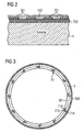
- FIG. 3 shows an outer ring 5, which has sensor structures 70 at regular intervals.
- the sensor structures 70 are constructed as structure pairs of a quadrilateral 710 and a combined structure 711, 712.
- the quadrilateral 710 is outside the load range 500 and serves for temperature compensation.
- the combined structure of the round area 711 is in the power circuit, ie in the load area 500, while the quadrangular area 712 serves the Anrome ist.
- the two structures, ie the square 710 of the temperature compensation and the combined structure 711, 712 are connected in series with each other. This has the advantage that, regardless of the temperature, this arrangement represents an ideal voltage divider.
- the load distribution via the bearing ring 5 can be measured.
- FIG. 4 shows a section of an electric motor 11.
- This has a spindle 200 and a spindle drive 201 on.
- the spindle drive 201 is connected at its first end to a rotor 81, which is fixed to an inner ring 3a of a first bearing 1a.
- the spindle drive 201 is fixed with an inner ring 3b of a second bearing 1b.
- rolling elements 4a spaced from the inner ring 3a, an outer ring 5a, which is fixed relative to a housing 6, arranged.
- an outer ring 5b of the second bearing 1b is spaced from the inner ring 3b by rolling elements 4b and arranged fixed relative to the housing 6.
- the housing 6 is connected to a stator 80, so that the housing 6 always remains at rest.
- Piezoresistive sensor layers are arranged on the end faces 31 and 51 of the inner rings 3a, 3b and the outer rings 5a, 5b of the first and second bearings 1a, 1b.
- the spindle drive 201 moves the spindle 200, which is fixed so that it does not rotate about its own axis, from the housing out. If the rotor is rotated in the opposite direction, the rotation of the spindle drive 201 causes the spindle 200 to move in the direction of the housing 6.
- both pulling and pushing forces can be introduced via the spindle into the actuator.
- a pressing force is oriented such that its direction of action along the spindle faces the housing 6.
- the resulting power flow through the motor 11 is designated by the reference numeral 90.
- the force flow through the motor 11 corresponding to this load case is designated by reference numeral 91.
- the bearings 1a, 1b have no faults to ensure low-friction operation.
- the functionality of the bearing is controlled according to the invention by the use of piezoresistive sensors.
- the piezoresistive force sensors described here are intended to enable a measurement of the load distribution on the rolling bearings mounted in the actuator, as well as to permit the measurement of the force impacts generated by defects on bearings or spindle. For this purpose, they are integrated directly into the load path of the actuator and thus allow a measurement that is much closer to the affected components than is possible by means of a structure-borne noise measurement. Due to the arrangement directly in the load path, the effects of damaged areas on the bearings as well as on the spindles can be detected.
Landscapes
- Engineering & Computer Science (AREA)
- General Engineering & Computer Science (AREA)
- Mechanical Engineering (AREA)
- Force Measurement Appropriate To Specific Purposes (AREA)
- General Electrical Machinery Utilizing Piezoelectricity, Electrostriction Or Magnetostriction (AREA)
Claims (23)
- Actionneur avec système intégré de surveillance d'état pour la reconnaissance et la surveillance d'irrégularités mécaniques de composants individuels de l'actionneur et/ou pour la mesure d'une répartition de charges (90, 91) sur ces composants, dans lequel l'actionneur contient au moins deux composants (3, 5) mobiles l'un par rapport à l'autre et respectivement dotés d'une première et d'une seconde zone de surface (31, 51), dans lequel les deux composants (3, 5) sont respectivement agencés avec leur première zone de surface de telle sorte que les deux premières zones de surface sont en contact l'une avec l'autre ou sont espacées l'une de l'autre par au moins un composant supplémentaire, dans lequel la seconde zone de surface (31, 51) d'au moins l'un des deux composants (3, 5) présente au moins un capteur piézorésistif (7) comme élément du système de surveillance d'état,
caractérisé en ce que
le au moins un capteur piézorésistif (7) est agencé dans le chemin de charge d'au moins l'un des deux composants (3, 5). - Actionneur selon la revendication précédente, caractérisé en ce que l'actionneur présente au moins deux capteurs piézorésistifs (7).
- Actionneur selon l'une quelconque des revendications précédentes, caractérisé en ce que la seconde zone de surface (31,51) d'au moins l'un des deux composants (3, 5) est en contact au moins par endroits avec au moins un autre élément, dans lequel le capteur piézorésistif (7) est agencé au moins partiellement dans la zone de contact entre la seconde zone de surface (31, 51) et l'autre élément.
- Actionneur selon l'une quelconque des revendications précédentes, caractérisé en ce que les au moins deux composants (3, 5) de l'actionneur sont une bague intérieure (3) et une bague extérieure (5) d'un palier de roulement (1), lesquelles peuvent tourner l'une par rapport à l'autre, et le au moins un composant supplémentaire de l'actionneur est une pluralité de corps de roulement (4), qui sont agencés entre la bague intérieure (3) et la bague extérieure (5).
- Actionneur selon la revendication précédente, caractérisé en ce que le capteur piézorésistif (7) est agencé axialement contre au moins l'un des épaulements de la bague extérieure (51), en particulier complètement ou partiellement entre au moins l'un des épaulements (51) et un boîtier (6), et/ou axialement contre au moins l'un des épaulements de la bague intérieure (31), en particulier complètement ou partiellement entre au moins l'un des épaulements de la bague intérieure (31) et un arbre d'entraînement (2) ou un élément de transition vers l'arbre d'entraînement (2).
- Actionneur selon l'une quelconque des revendications 4 ou 5, caractérisé en ce qu'au moins l'un des épaulements de la bague extérieure (51) et/ou de la bague intérieure (31) présente des capteurs piézorésistifs (7), avantageusement le long du sens périphérique de la bague extérieure (5) et/ou de la bague intérieure (3), avantageusement à intervalles réguliers.
- Actionneur selon l'une quelconque des revendications 4 à 6, caractérisé en ce que la bague intérieure (3) est conçue sous forme de broche (200) et la bague extérieure (5) forme un écrou de broche avec le capteur piézorésistif (7).
- Actionneur selon l'une quelconque des revendications précédentes, caractérisé en ce que le système de surveillance d'état contient au moins un élément de compensation de température, qui est agencé en particulier en dehors du chemin de charge (500), de préférence dans la seconde zone de surface (31, 51) d'au moins l'un des composants de l'actionneur, de préférence dans la zone du capteur piézorésistif (7) ou à proximité de celui-ci.
- Actionneur selon l'une quelconque des revendications précédentes, caractérisé en ce que le au moins un capteur piézorésistif (7) et le au moins un élément de compensation de température sont commutés de telle sorte qu'ils forment un montage en série ou un montage en pont, en particulier un montage en pont de Wheatstone.
- Actionneur selon l'une quelconque des revendications précédentes, caractérisé en ce que le au moins un capteur piézorésistif (7) est conçu sous forme d'au moins un point de capteur dans un revêtement de surface (700) ou en ce que le au moins un capteur piézorésistif (7) est un revêtement de surface (700) fabriqué dans un matériau piézorésistif ou contenant un tel matériau.
- Actionneur selon la revendication précédente, caractérisé en ce que le point de capteur et/ou le revêtement de surface (700) fabriqué dans un matériau piézorésistif ou contenant un tel matériau est une couche d'hydrocarbure dopée ou non dopée, qui est éventuellement dopée avec du tungstène, du chrome, de l'argent, du titane, de l'or ou du platine.
- Actionneur selon l'une quelconque des revendications 10 ou 11, caractérisé en ce que le capteur piézorésistif (7) présente des électrodes (701), en particulier sur le côté du point de capteur et/ou du revêtement de surface (700), lequel côté étant opposé à la seconde zone de surface (31, 51) de l'un des composants de l'actionneur, électrodes avec lesquelles le au moins un point de capteur et/ou le revêtement de surface (700) fabriqué dans un matériau piézorésistif ou contenant un tel matériau peu(ven)t entrer en contact et peu(ven)t être relié(s) à une source de tension, en particulier une source de tension constante, ou à une source de courant, en particulier une source de courant constant.
- Actionneur selon la revendication précédente, caractérisé en ce que les électrodes (701) sont conçues sous la forme d'une couche de métal mince, qui est de préférence en chrome, en composés chrome-nickel ou en titane, ou contient au moins l'un de ces matériaux.
- Actionneur selon l'une quelconque des revendications 12 ou 13, caractérisé en ce que respectivement deux électrodes (701) sont agencées à proximité l'une de l'autre, dans lequel une première électrode, qui présente une première zone pour la mesure de la force et une seconde zone pour la mise en contact, est agencée avec la première zone dans le chemin de charge (500) et avec la seconde zone à l'extérieur du chemin de charge, et une seconde électrode pour la compensation de température est agencée à l'extérieur du chemin de charge.
- Actionneur selon l'une quelconque des revendications précédentes, caractérisé en ce qu'une couche d'isolation et/ou de protection contre l'usure (702) est agencée par endroits sur le côté du point de capteur et/ou du revêtement de surface, lequel côté étant opposé à la seconde zone de surface (31, 51) de l'un des composants de l'actionneur, et sur les électrodes (701) agencées dessus, dans laquelle la couche d'isolation et/ou de protection contre l'usure (702) est de préférence fabriquée dans une couche d'hydrocarbure dopée avec du silicium, dopée avec du silicium et de l'oxygène, dopée avec de l'aluminium ou dopée avec du nitrure d'aluminium ou contient une telle couche.
- Actionneur selon l'une quelconque des revendications précédentes, caractérisé en ce que le au moins un capteur piézorésistif (7) est relié par une liaison électrique à une unité d'analyse et une électronique de capteur.
- Procédé pour détecter et surveiller des irrégularités mécaniques de composants individuels d'un actionneur selon l'une quelconque des revendications 1 à 16 et/ou pour mesurer une répartition de charges sur ces composants, dans lequel l'actionneur contient au moins deux composants (3, 5) comprenant respectivement une première et une seconde zone de surface (31, 51), dans lequel les deux composants (3, 5) sont mobiles l'un par rapport à l'autre et sont respectivement agencés avec leur première zone de surface l'un par rapport à l'autre de telle sorte que les deux premières zones de surface sont au moins par endroits en contact l'une avec l'autre, ou sont espacées l'une de l'autre par au moins un composant supplémentaire,
caractérisé en ce que
les forces normales agissant sur au moins l'un des composants (3, 5) pendant le mouvement relatif des deux composants (3, 5). - Procédé selon la revendication précédente, caractérisé en ce que les forces normales agissant sur au moins l'un des composants (3, 5) dans la zone du chemin de charge (500) sont mesurées.
- Procédé selon l'une quelconque des revendications 17 ou 18, caractérisé en ce que les valeurs mesurées sont analysées au moyen de procédés appropriés du traitement de signal, en particulier au moyen d'une analyse fréquentielle et/ou au moyen d'une analyse temps-fréquence et/ou au moyen d'une analyse échelle-fréquence.
- Procédé selon l'une quelconque des revendications 17 à 19, caractérisé en ce que les deux composants de l'actionneur (3, 5) et éventuellement le au moins un composant supplémentaire forment un palier de roulement (1) avec une bague extérieure et une bague intérieure (3, 5) ainsi que des corps de roulement (4), de préférence un entraînement de broche (201) avec une bague extérieure (5) et une bague intérieure (3) conçue sous la forme d'une broche (200), et les forces normales agissant axialement sur les épaulements de la bague extérieure et/ou de la bague intérieure (51, 31) sont mesurées.
- Procédé selon l'une quelconque des revendications 17 à 20, caractérisé en ce que les forces normales sont mesurées au moyen d'un capteur piézorésistif (7).
- Procédé pour fabriquer un actionneur avec système intégré de surveillance d'état selon l'une quelconque des revendications 1 à 16, dans lequel l'actionneur contient au moins deux composants (3, 5) mobiles l'un par rapport à l'autre et respectivement dotés d'une première et d'une seconde zone de surface (31, 51), dans lequel les deux composants (3, 5) sont respectivement agencés avec leur première zone de surface l'un par rapport à l'autre de telle sorte que les deux premières zones de surface sont en contact l'une avec l'autre ou sont espacées l'une de l'autre par au moins un composant supplémentaire,
caractérisé en ce que
un capteur piézorésistif (7) est positionné sur au moins l'un des deux composants (3, 5) dans leur seconde zone de surface (31, 51). - Utilisation d'un actionneur avec système intégré de surveillance d'état selon l'une quelconque des revendications 1 à 16 et du procédé pour détecter et surveiller des irrégularités mécaniques d'un actionneur et pour mesurer une répartition de charges sur cet actionneur selon la revendication 17 dans des systèmes de commande et de réglage, en particulier dans des systèmes de commande de vol d'aéronefs, dans le domaine de la commande de véhicule et/ou dans le domaine de la production énergétique.
Applications Claiming Priority (1)
| Application Number | Priority Date | Filing Date | Title |
|---|---|---|---|
| DE102009040344.2A DE102009040344B4 (de) | 2009-09-08 | 2009-09-08 | Aktuator mit integriertem Zustandsüberwachungssystem sowie Verfahren zur Zustandsüberwachung sowie Verfahren zur Herstellung eines Aktuators |
Publications (2)
| Publication Number | Publication Date |
|---|---|
| EP2292513A1 EP2292513A1 (fr) | 2011-03-09 |
| EP2292513B1 true EP2292513B1 (fr) | 2012-06-27 |
Family
ID=43217002
Family Applications (1)
| Application Number | Title | Priority Date | Filing Date |
|---|---|---|---|
| EP10009257A Not-in-force EP2292513B1 (fr) | 2009-09-08 | 2010-09-06 | Actionneur doté d'un système de surveillance d'état intégré et procédé de fabrication d'un actionneur |
Country Status (3)
| Country | Link |
|---|---|
| US (1) | US8405265B2 (fr) |
| EP (1) | EP2292513B1 (fr) |
| DE (1) | DE102009040344B4 (fr) |
Cited By (1)
| Publication number | Priority date | Publication date | Assignee | Title |
|---|---|---|---|---|
| DE102019210525A1 (de) * | 2019-07-17 | 2021-01-21 | Volkswagen Aktiengesellschaft | Überwachungsgerät |
Families Citing this family (8)
| Publication number | Priority date | Publication date | Assignee | Title |
|---|---|---|---|---|
| DE102011103848A1 (de) | 2011-05-27 | 2012-11-29 | Deutsches Zentrum für Luft- und Raumfahrt e.V. | Sensoreinrichtung |
| CN103047927B (zh) * | 2012-12-18 | 2016-03-02 | 无锡莱顿电子有限公司 | 陶瓷基底压阻式应变片 |
| DE102013222150B4 (de) | 2013-10-31 | 2018-03-01 | Schaeffler Technologies AG & Co. KG | Anbaugerät oder Landwirtschaftsfahrzeug mit einem Überwachungsmodul |
| FR3016607B1 (fr) * | 2014-01-20 | 2016-01-22 | Sagem Defense Securite | Actionneur de commande d'un plan horizontal de stabilisation d'un aeronef |
| EP2924304B1 (fr) * | 2014-03-24 | 2023-12-13 | Goodrich Actuation Systems SAS | Système de détection de charge |
| CN105718695B (zh) * | 2016-02-01 | 2021-06-22 | 华北电力大学 | 一种基于压缩传感的风场重建方法 |
| DE102019111937A1 (de) * | 2019-05-08 | 2020-11-12 | Schaeffler Technologies AG & Co. KG | Smart-Aktor mit Schwingungsverarbeitung und Verfahren zum Auswerten von Schwingungen an einer Getriebekomponente |
| CN114858206B (zh) * | 2022-03-01 | 2025-04-04 | 中国商用飞机有限责任公司北京民用飞机技术研究中心 | 航空电机检测方法、装置、计算机设备及存储介质 |
Family Cites Families (11)
| Publication number | Priority date | Publication date | Assignee | Title |
|---|---|---|---|---|
| US5509198A (en) * | 1992-02-24 | 1996-04-23 | Nsk Ltd. | Preloading method for preload-adjustable rolling bearing and manufacture of the same |
| US6174088B1 (en) * | 1997-12-15 | 2001-01-16 | Nsk Ltd. | Rolling bearing unit with rotation speed sensor |
| DE60131571T2 (de) * | 2000-04-10 | 2008-10-23 | The Timken Company, Canton | Lageranordnung mit sensoren zur überwachung von lasten |
| FR2865254B1 (fr) * | 2004-01-21 | 2007-05-11 | Goodrich Actuation Systems | Dispositif de detection de transfert de charge par cisaillement d'un pion ruptible |
| US7834494B2 (en) * | 2004-06-04 | 2010-11-16 | The Boeing Company | Fault-tolerant electromechanical actuator having a torque sensing control system |
| EP1666744A1 (fr) * | 2004-12-06 | 2006-06-07 | Ab Skf | Unité palier comprenant un élément en tôle |
| WO2006107938A2 (fr) * | 2005-04-04 | 2006-10-12 | Danaher Motion, L.L.C. | Ensemble a deplacement lineaire avec systeme de surveillance, et procede de surveillance |
| EP1764186A1 (fr) * | 2005-09-14 | 2007-03-21 | Werner Kluft | Système de contrôle d'une opération d'usinage avec des capteurs piézoélectriques axiaux dans la broche de travail |
| US7971490B2 (en) * | 2006-03-03 | 2011-07-05 | Flowserve Management Company | Load measurement method and device |
| DE102006019942B4 (de) * | 2006-04-28 | 2016-01-07 | Fraunhofer-Gesellschaft zur Förderung der angewandten Forschung e.V. | Kraftmessvorrichtung zur Messung der Kraft bei Festkörperaktoren, Verfahren zur Messung einer Kraft sowie Verwendung der Kraftmessvorrichtung |
| US8002251B2 (en) * | 2007-11-14 | 2011-08-23 | Honeywell International Inc. | Vibration reduction system employing active bearing mounts |
-
2009
- 2009-09-08 DE DE102009040344.2A patent/DE102009040344B4/de not_active Expired - Fee Related
-
2010
- 2010-09-06 EP EP10009257A patent/EP2292513B1/fr not_active Not-in-force
- 2010-09-07 US US12/876,285 patent/US8405265B2/en not_active Expired - Fee Related
Cited By (1)
| Publication number | Priority date | Publication date | Assignee | Title |
|---|---|---|---|---|
| DE102019210525A1 (de) * | 2019-07-17 | 2021-01-21 | Volkswagen Aktiengesellschaft | Überwachungsgerät |
Also Published As
| Publication number | Publication date |
|---|---|
| DE102009040344B4 (de) | 2016-03-24 |
| EP2292513A1 (fr) | 2011-03-09 |
| US20110057550A1 (en) | 2011-03-10 |
| DE102009040344A1 (de) | 2011-03-17 |
| US8405265B2 (en) | 2013-03-26 |
Similar Documents
| Publication | Publication Date | Title |
|---|---|---|
| EP2292513B1 (fr) | Actionneur doté d'un système de surveillance d'état intégré et procédé de fabrication d'un actionneur | |
| EP3919781B1 (fr) | Module amélioré hélicoïdale et installation comprenant le module amélioré | |
| EP1627213B1 (fr) | Palier a roulement comportant une electronique polymere | |
| EP3037796B1 (fr) | Corps de ressort pour une cellule de mesure de couple | |
| DE102015100655A1 (de) | Linearführungseinrichtung für eine Vorschubachse einer Werkzeugmaschine | |
| EP2325654A1 (fr) | Palier à roulement avec capteur | |
| DE10308301B3 (de) | Flugzeughochauftriebssystem mit Überlastsicherung | |
| DE102010044678A1 (de) | Überwachungsvorrichtung für ein Stellsystem eines Flugzeugs, Stellsystem und Verfahren zur Rekonfiguration des Stellsystems | |
| EP3114449A1 (fr) | Pièce structurale comprenant un élément de mesure comportant au moins un capteur | |
| EP2473818B1 (fr) | Dispositif pour mesurer et/ou enregistrer des distances et des variations de distance et dispositif pour mesurer et/ou enregistrer des contraintes mécaniques | |
| EP2891827A2 (fr) | Dispositif de découplage à actionnement électromécanique pour actionneurs | |
| DE102016015382B4 (de) | Aktuator zum Betätigen einer Einrichtung eines Fluggeräts | |
| EP3728880B1 (fr) | Dispositif et procédé de détermination d'une grandeur d'état | |
| WO2020211891A1 (fr) | Actionneur manuel doté d'un système de capteurs pour la détection du couple | |
| EP2302242B1 (fr) | Procédé et dispositif de conditionnement de systèmes de palier pour arbres | |
| EP1883979B1 (fr) | Systeme d'entrainement a actionneurs a l'etat solide pourvu d'un arbre pouvant etre anime d'un mouvement de rotation | |
| DE102023112298A1 (de) | Stellantrieb mit Elektromotor | |
| DE102010024850A1 (de) | Rotierbares Bauelement und Verfahren zur Ermittlung der Drehzahl eines rotierbaren Bauelements | |
| WO2022127968A1 (fr) | Ensemble de direction, véhicule et procédé de détermination d'un couple de direction d'un système de direction | |
| DE102014100435B4 (de) | Sensor und Linearbewegungsanordnung | |
| WO2011064060A1 (fr) | Palier de roulement avec une mesure matérialisée | |
| DE102013222150A1 (de) | Überwachungsmodul mit messendem Lager zum Erfassen eines Betriebszustands, insbesondere von Bodenbearbeitungsgeräten | |
| DE102023134168A1 (de) | Spannungswellengetriebe mit Sensoren | |
| DE102010024805A1 (de) | Einrichtung mit einem Aktuator und Verfahren zur Steuerung eines Aktuators | |
| DE102022206590A1 (de) | Lenkgetriebe mit Positionssensorik sowie elektrisches Lenksystem mit dem Lenkgetriebe |
Legal Events
| Date | Code | Title | Description |
|---|---|---|---|
| PUAI | Public reference made under article 153(3) epc to a published international application that has entered the european phase |
Free format text: ORIGINAL CODE: 0009012 |
|
| AK | Designated contracting states |
Kind code of ref document: A1 Designated state(s): AL AT BE BG CH CY CZ DE DK EE ES FI FR GB GR HR HU IE IS IT LI LT LU LV MC MK MT NL NO PL PT RO SE SI SK SM TR |
|
| AX | Request for extension of the european patent |
Extension state: BA ME RS |
|
| 17P | Request for examination filed |
Effective date: 20110909 |
|
| GRAP | Despatch of communication of intention to grant a patent |
Free format text: ORIGINAL CODE: EPIDOSNIGR1 |
|
| GRAS | Grant fee paid |
Free format text: ORIGINAL CODE: EPIDOSNIGR3 |
|
| GRAA | (expected) grant |
Free format text: ORIGINAL CODE: 0009210 |
|
| AK | Designated contracting states |
Kind code of ref document: B1 Designated state(s): AL AT BE BG CH CY CZ DE DK EE ES FI FR GB GR HR HU IE IS IT LI LT LU LV MC MK MT NL NO PL PT RO SE SI SK SM TR |
|
| REG | Reference to a national code |
Ref country code: GB Ref legal event code: FG4D Free format text: NOT ENGLISH |
|
| REG | Reference to a national code |
Ref country code: CH Ref legal event code: EP |
|
| REG | Reference to a national code |
Ref country code: AT Ref legal event code: REF Ref document number: 564038 Country of ref document: AT Kind code of ref document: T Effective date: 20120715 |
|
| REG | Reference to a national code |
Ref country code: IE Ref legal event code: FG4D Free format text: LANGUAGE OF EP DOCUMENT: GERMAN |
|
| REG | Reference to a national code |
Ref country code: DE Ref legal event code: R096 Ref document number: 502010000928 Country of ref document: DE Effective date: 20120823 |
|
| PG25 | Lapsed in a contracting state [announced via postgrant information from national office to epo] |
Ref country code: SE Free format text: LAPSE BECAUSE OF FAILURE TO SUBMIT A TRANSLATION OF THE DESCRIPTION OR TO PAY THE FEE WITHIN THE PRESCRIBED TIME-LIMIT Effective date: 20120627 Ref country code: NO Free format text: LAPSE BECAUSE OF FAILURE TO SUBMIT A TRANSLATION OF THE DESCRIPTION OR TO PAY THE FEE WITHIN THE PRESCRIBED TIME-LIMIT Effective date: 20120927 Ref country code: FI Free format text: LAPSE BECAUSE OF FAILURE TO SUBMIT A TRANSLATION OF THE DESCRIPTION OR TO PAY THE FEE WITHIN THE PRESCRIBED TIME-LIMIT Effective date: 20120627 Ref country code: LT Free format text: LAPSE BECAUSE OF FAILURE TO SUBMIT A TRANSLATION OF THE DESCRIPTION OR TO PAY THE FEE WITHIN THE PRESCRIBED TIME-LIMIT Effective date: 20120627 |
|
| REG | Reference to a national code |
Ref country code: NL Ref legal event code: VDEP Effective date: 20120627 |
|
| REG | Reference to a national code |
Ref country code: LT Ref legal event code: MG4D Effective date: 20120627 |
|
| PG25 | Lapsed in a contracting state [announced via postgrant information from national office to epo] |
Ref country code: HR Free format text: LAPSE BECAUSE OF FAILURE TO SUBMIT A TRANSLATION OF THE DESCRIPTION OR TO PAY THE FEE WITHIN THE PRESCRIBED TIME-LIMIT Effective date: 20120627 Ref country code: GR Free format text: LAPSE BECAUSE OF FAILURE TO SUBMIT A TRANSLATION OF THE DESCRIPTION OR TO PAY THE FEE WITHIN THE PRESCRIBED TIME-LIMIT Effective date: 20120928 Ref country code: SI Free format text: LAPSE BECAUSE OF FAILURE TO SUBMIT A TRANSLATION OF THE DESCRIPTION OR TO PAY THE FEE WITHIN THE PRESCRIBED TIME-LIMIT Effective date: 20120627 Ref country code: LV Free format text: LAPSE BECAUSE OF FAILURE TO SUBMIT A TRANSLATION OF THE DESCRIPTION OR TO PAY THE FEE WITHIN THE PRESCRIBED TIME-LIMIT Effective date: 20120627 |
|
| PG25 | Lapsed in a contracting state [announced via postgrant information from national office to epo] |
Ref country code: CZ Free format text: LAPSE BECAUSE OF FAILURE TO SUBMIT A TRANSLATION OF THE DESCRIPTION OR TO PAY THE FEE WITHIN THE PRESCRIBED TIME-LIMIT Effective date: 20120627 Ref country code: CY Free format text: LAPSE BECAUSE OF FAILURE TO SUBMIT A TRANSLATION OF THE DESCRIPTION OR TO PAY THE FEE WITHIN THE PRESCRIBED TIME-LIMIT Effective date: 20120627 Ref country code: IS Free format text: LAPSE BECAUSE OF FAILURE TO SUBMIT A TRANSLATION OF THE DESCRIPTION OR TO PAY THE FEE WITHIN THE PRESCRIBED TIME-LIMIT Effective date: 20121027 Ref country code: EE Free format text: LAPSE BECAUSE OF FAILURE TO SUBMIT A TRANSLATION OF THE DESCRIPTION OR TO PAY THE FEE WITHIN THE PRESCRIBED TIME-LIMIT Effective date: 20120627 Ref country code: SK Free format text: LAPSE BECAUSE OF FAILURE TO SUBMIT A TRANSLATION OF THE DESCRIPTION OR TO PAY THE FEE WITHIN THE PRESCRIBED TIME-LIMIT Effective date: 20120627 Ref country code: RO Free format text: LAPSE BECAUSE OF FAILURE TO SUBMIT A TRANSLATION OF THE DESCRIPTION OR TO PAY THE FEE WITHIN THE PRESCRIBED TIME-LIMIT Effective date: 20120627 |
|
| PG25 | Lapsed in a contracting state [announced via postgrant information from national office to epo] |
Ref country code: PL Free format text: LAPSE BECAUSE OF FAILURE TO SUBMIT A TRANSLATION OF THE DESCRIPTION OR TO PAY THE FEE WITHIN THE PRESCRIBED TIME-LIMIT Effective date: 20120627 Ref country code: IT Free format text: LAPSE BECAUSE OF FAILURE TO SUBMIT A TRANSLATION OF THE DESCRIPTION OR TO PAY THE FEE WITHIN THE PRESCRIBED TIME-LIMIT Effective date: 20120627 Ref country code: PT Free format text: LAPSE BECAUSE OF FAILURE TO SUBMIT A TRANSLATION OF THE DESCRIPTION OR TO PAY THE FEE WITHIN THE PRESCRIBED TIME-LIMIT Effective date: 20121029 |
|
| PG25 | Lapsed in a contracting state [announced via postgrant information from national office to epo] |
Ref country code: NL Free format text: LAPSE BECAUSE OF FAILURE TO SUBMIT A TRANSLATION OF THE DESCRIPTION OR TO PAY THE FEE WITHIN THE PRESCRIBED TIME-LIMIT Effective date: 20120627 |
|
| BERE | Be: lapsed |
Owner name: FRAUNHOFER-GESELLSCHAFT ZUR FORDERUNG DER ANGEWAN Effective date: 20120930 |
|
| PG25 | Lapsed in a contracting state [announced via postgrant information from national office to epo] |
Ref country code: MC Free format text: LAPSE BECAUSE OF NON-PAYMENT OF DUE FEES Effective date: 20120930 Ref country code: DK Free format text: LAPSE BECAUSE OF FAILURE TO SUBMIT A TRANSLATION OF THE DESCRIPTION OR TO PAY THE FEE WITHIN THE PRESCRIBED TIME-LIMIT Effective date: 20120627 Ref country code: ES Free format text: LAPSE BECAUSE OF FAILURE TO SUBMIT A TRANSLATION OF THE DESCRIPTION OR TO PAY THE FEE WITHIN THE PRESCRIBED TIME-LIMIT Effective date: 20121008 |
|
| PLBE | No opposition filed within time limit |
Free format text: ORIGINAL CODE: 0009261 |
|
| STAA | Information on the status of an ep patent application or granted ep patent |
Free format text: STATUS: NO OPPOSITION FILED WITHIN TIME LIMIT |
|
| RAP2 | Party data changed (patent owner data changed or rights of a patent transferred) |
Owner name: DEUTSCHES ZENTRUM FUER LUFT- UND RAUMFAHRT E.V. Owner name: FRAUNHOFER-GESELLSCHAFT ZUR FOERDERUNG DER ANGEWAN |
|
| 26N | No opposition filed |
Effective date: 20130328 |
|
| REG | Reference to a national code |
Ref country code: IE Ref legal event code: MM4A |
|
| REG | Reference to a national code |
Ref country code: DE Ref legal event code: R081 Ref document number: 502010000928 Country of ref document: DE Owner name: DEUTSCHES ZENTRUM FUER LUFT- UND RAUMFAHRT E.V, DE Free format text: FORMER OWNER: FRAUNHOFER-GESELLSCHAFT ZUR FOERDERUNG DER ANGEWANDTEN FORSCHUNG E.V., 80686 MUENCHEN, DE Effective date: 20130521 Ref country code: DE Ref legal event code: R081 Ref document number: 502010000928 Country of ref document: DE Owner name: FRAUNHOFER-GESELLSCHAFT ZUR FOERDERUNG DER ANG, DE Free format text: FORMER OWNER: FRAUNHOFER-GESELLSCHAFT ZUR FOERDERUNG DER ANGEWANDTEN FORSCHUNG E.V., 80686 MUENCHEN, DE Effective date: 20130521 |
|
| REG | Reference to a national code |
Ref country code: DE Ref legal event code: R097 Ref document number: 502010000928 Country of ref document: DE Effective date: 20130328 |
|
| PG25 | Lapsed in a contracting state [announced via postgrant information from national office to epo] |
Ref country code: BG Free format text: LAPSE BECAUSE OF FAILURE TO SUBMIT A TRANSLATION OF THE DESCRIPTION OR TO PAY THE FEE WITHIN THE PRESCRIBED TIME-LIMIT Effective date: 20120927 Ref country code: BE Free format text: LAPSE BECAUSE OF NON-PAYMENT OF DUE FEES Effective date: 20120930 Ref country code: IE Free format text: LAPSE BECAUSE OF NON-PAYMENT OF DUE FEES Effective date: 20120906 |
|
| PG25 | Lapsed in a contracting state [announced via postgrant information from national office to epo] |
Ref country code: AL Free format text: LAPSE BECAUSE OF FAILURE TO SUBMIT A TRANSLATION OF THE DESCRIPTION OR TO PAY THE FEE WITHIN THE PRESCRIBED TIME-LIMIT Effective date: 20120627 Ref country code: MT Free format text: LAPSE BECAUSE OF FAILURE TO SUBMIT A TRANSLATION OF THE DESCRIPTION OR TO PAY THE FEE WITHIN THE PRESCRIBED TIME-LIMIT Effective date: 20120627 |
|
| PG25 | Lapsed in a contracting state [announced via postgrant information from national office to epo] |
Ref country code: TR Free format text: LAPSE BECAUSE OF FAILURE TO SUBMIT A TRANSLATION OF THE DESCRIPTION OR TO PAY THE FEE WITHIN THE PRESCRIBED TIME-LIMIT Effective date: 20120627 |
|
| PG25 | Lapsed in a contracting state [announced via postgrant information from national office to epo] |
Ref country code: SM Free format text: LAPSE BECAUSE OF FAILURE TO SUBMIT A TRANSLATION OF THE DESCRIPTION OR TO PAY THE FEE WITHIN THE PRESCRIBED TIME-LIMIT Effective date: 20120627 Ref country code: LU Free format text: LAPSE BECAUSE OF NON-PAYMENT OF DUE FEES Effective date: 20120906 |
|
| PG25 | Lapsed in a contracting state [announced via postgrant information from national office to epo] |
Ref country code: HU Free format text: LAPSE BECAUSE OF FAILURE TO SUBMIT A TRANSLATION OF THE DESCRIPTION OR TO PAY THE FEE WITHIN THE PRESCRIBED TIME-LIMIT Effective date: 20100906 |
|
| REG | Reference to a national code |
Ref country code: CH Ref legal event code: PL |
|
| PG25 | Lapsed in a contracting state [announced via postgrant information from national office to epo] |
Ref country code: CH Free format text: LAPSE BECAUSE OF NON-PAYMENT OF DUE FEES Effective date: 20140930 Ref country code: LI Free format text: LAPSE BECAUSE OF NON-PAYMENT OF DUE FEES Effective date: 20140930 Ref country code: MK Free format text: LAPSE BECAUSE OF FAILURE TO SUBMIT A TRANSLATION OF THE DESCRIPTION OR TO PAY THE FEE WITHIN THE PRESCRIBED TIME-LIMIT Effective date: 20120627 |
|
| REG | Reference to a national code |
Ref country code: FR Ref legal event code: PLFP Year of fee payment: 7 |
|
| REG | Reference to a national code |
Ref country code: AT Ref legal event code: MM01 Ref document number: 564038 Country of ref document: AT Kind code of ref document: T Effective date: 20150906 |
|
| PG25 | Lapsed in a contracting state [announced via postgrant information from national office to epo] |
Ref country code: AT Free format text: LAPSE BECAUSE OF NON-PAYMENT OF DUE FEES Effective date: 20150906 |
|
| REG | Reference to a national code |
Ref country code: FR Ref legal event code: PLFP Year of fee payment: 8 |
|
| REG | Reference to a national code |
Ref country code: FR Ref legal event code: PLFP Year of fee payment: 9 |
|
| REG | Reference to a national code |
Ref country code: DE Ref legal event code: R084 Ref document number: 502010000928 Country of ref document: DE |
|
| PGFP | Annual fee paid to national office [announced via postgrant information from national office to epo] |
Ref country code: GB Payment date: 20220927 Year of fee payment: 13 |
|
| PGFP | Annual fee paid to national office [announced via postgrant information from national office to epo] |
Ref country code: FR Payment date: 20220920 Year of fee payment: 13 |
|
| PGFP | Annual fee paid to national office [announced via postgrant information from national office to epo] |
Ref country code: DE Payment date: 20230919 Year of fee payment: 14 |
|
| GBPC | Gb: european patent ceased through non-payment of renewal fee |
Effective date: 20230906 |
|
| PG25 | Lapsed in a contracting state [announced via postgrant information from national office to epo] |
Ref country code: GB Free format text: LAPSE BECAUSE OF NON-PAYMENT OF DUE FEES Effective date: 20230906 |
|
| PG25 | Lapsed in a contracting state [announced via postgrant information from national office to epo] |
Ref country code: GB Free format text: LAPSE BECAUSE OF NON-PAYMENT OF DUE FEES Effective date: 20230906 Ref country code: FR Free format text: LAPSE BECAUSE OF NON-PAYMENT OF DUE FEES Effective date: 20230930 |
|
| REG | Reference to a national code |
Ref country code: DE Ref legal event code: R119 Ref document number: 502010000928 Country of ref document: DE |
|
| PG25 | Lapsed in a contracting state [announced via postgrant information from national office to epo] |
Ref country code: DE Free format text: LAPSE BECAUSE OF NON-PAYMENT OF DUE FEES Effective date: 20250401 |