EP2292545A1 - Dispositif d affichage d étage de destination pour ascenseur - Google Patents
Dispositif d affichage d étage de destination pour ascenseur Download PDFInfo
- Publication number
- EP2292545A1 EP2292545A1 EP08777769A EP08777769A EP2292545A1 EP 2292545 A1 EP2292545 A1 EP 2292545A1 EP 08777769 A EP08777769 A EP 08777769A EP 08777769 A EP08777769 A EP 08777769A EP 2292545 A1 EP2292545 A1 EP 2292545A1
- Authority
- EP
- European Patent Office
- Prior art keywords
- indication
- destination
- floor
- indicated
- destination floor
- Prior art date
- Legal status (The legal status is an assumption and is not a legal conclusion. Google has not performed a legal analysis and makes no representation as to the accuracy of the status listed.)
- Withdrawn
Links
Images


Classifications
-
- B—PERFORMING OPERATIONS; TRANSPORTING
- B66—HOISTING; LIFTING; HAULING
- B66B—ELEVATORS; ESCALATORS OR MOVING WALKWAYS
- B66B3/00—Applications of devices for indicating or signalling operating conditions of elevators
- B66B3/02—Position or depth indicators
Definitions
- the present invention relates to a destination floor indication device of an elevator.
- the present invention has been made in order to solve the problem described above, and the object of the invention is to provide a destination floor indication device of an elevator which is excellent in the viewability of destination floor indications and can quickly indicate destination floors.
- a destination floor indication device of an elevator includes an indication device provided in at least either a hall or a car of an elevator; an indication information storage device which stores a maximum number of indications of destination floors which are caused to be indicated simultaneously on one screen of the indication device, the maximum number of indications being larger than 1; and an indication controller which causes destination floors to be indicated simultaneously on the indication device when the number of destination floors caused to be indicated on the indication device is smaller than the maximum number of indications, and which divides destination floors into a number smaller than the maximum number of indications and causes the destination floors to be indicated on the indication device in a switching manner when the number of destination floors caused to be indicated on the indication device is larger than the maximum number of indications.
- a destination floor indication device of an elevator which is excellent in the viewability of destination floor indications and can quickly indicate destination floors.
- FIG. 1 is a general block diagram of a destination floor indication device of an elevator in Embodiment 1 of the present invention.
- reference numeral 1 denotes an elevator controller.
- This elevator controller 1 is connected to a destination floor indication device 3 via a communication channel 2.
- This destination floor indication device 3 is provided in a hall or a car of an elevator in quantities of at least one.
- This destination floor indication device 3 is provided with an indication section 4, a communication section 5, a microcomputer 6, a memory section 7, an indication information storage section 8 and an indication control section 9.
- the indication section 4 is composed of an indication device, such as a liquid crystal display, a plasma display, an LED or a cathode-ray tube.
- the communication section 5 controls the communication channel 2.
- the microcomputer 6 controls the whole destination floor indication device 3.
- the memory section 7 is composed of a memory section for program storage and a work memory section.
- the memory section for program storage stores indication control programs.
- the work memory section reserves a work area for executing the indication control programs.
- the indication information storage section 8 stores indication information about characters and graphics of destination floors indicated in the indication section 4. Also, the indication information storage section 8 stores a maximum number of indications of destination floors which are caused to be indicated simultaneously on one screen of the indication section 4; this maximum number of indications is larger than 1. That is, the indication information storage section 8 functions as a storage device which stores various kinds of information necessary for destination floor indications.
- the indication control section 9 controls screen indications of the indication section 4 under instructions from the microcomputer 6. That is, the indication control section 9 functions as a controller which controls destination floor indications.
- the indication information storage section 8 and the memory section 7 are composed of a memory device, such as a hard disk drive, a nonvolatile memory and a dynamic random access memory.
- the indication information storage section 8 and the memory section 7 may sometimes be built into the microcomputer 6.
- destination floor information is sent from the elevator controller 1 to the microcomputer 6 via the communication channel 2 and the communication section 5.
- the microcomputer 6 acts on the basis of an indication control program while using the work memory section. Concretely, the microcomputer 6 takes indication information responsive to the destination floor information from the indication information storage section 8 and sends the indication information to the indication control section 9.
- the indication control section 9 causes the indication section 4 to indicate destination floors on the basis of the indication information in question.
- the indication control section 9 causes the destination floors to be indicated simultaneously on the indication section 4.
- the indication control section 9 divides the destination floors into a number which is smaller than the number of maximum indications, and causes the destination floors to be indicated on the indication section 4 in a switching manner.
- FIG. 2 is a diagram showing a screen indicated by the destination floor indication device of an elevator in Embodiment 1 of the present invention.
- the message 10 "THE ELEVATOR WILL STOP AT THE FLOORS: "is indicated as a still image in the lower part of the screen of the indication section 4. This indication may show other words and may not be a still image.
- the indication control section 9 creates a destination floor indication arrangement, which is the arrangement of destination floors, from the destination floor information. It is supposed that the number 6 is set as the maximum number of indications in the indication information storage section 8. In this case, it is possible to indicate up to six destination floors on the indication section 4.
- 8 ⁇ 6 1.333 and the destination floors are divided into two screens. And the indication positions of the destination floors in the indication section 4 are calculated from the number of necessary screens and the number of destination floors per screen. And a screen containing the nearest floor in the traveling direction of the elevator is indicated for a given time. More concretely, destination floors for one screen from the nearest destination floor in the traveling direction of the elevator are indicated in the indication section 4.
- the 5th floor, the 7th floor, the 10th floor, the 11th floor, the 12th floor and the 15th floor are indicated.
- the 5th floor, the 7th floor and the 10th floor are indicated in the upper area of the indication section 4, and the 11th floor, the 12th floor and the 15th floor are indicated in the lower area of the indication section 4.
- the screen of the indication section 4 switches and the 17th floor and the 19th floor are indicated.
- the 17th floor is indicated on the left side of the upper area of the indication section 4, and the 19th floor is indicated in the middle of the upper area of the indication section 4.
- these indication positions are not especially limited.
- the indication positions may be horizontally centered or they may be vertically centered. Concretely, it may be ensured that when the 5th floor is first registered as a destination floor, the 5th floor is indicated in the middle of the indication section 4. It may be ensured that when the 10th floor is then registered as a destination floor, the 5th floor and the 10th floor are indicated in the middle of the indication section 4. It may be ensured that when the 7th floor is then registered as a destination floor, the floors are indicated in the middle of the indication section 4 in the order of the 5th floor, the 7th floor and the 10th floor.
- FIG. 3 is a flowchart showing the operation of the destination floor indication device of an elevator in Embodiment 1 of the present invention expected when this destination floor indication device indicates destination floors.
- Step S1 an initial screen of a background screen, the message 10 and the like is indicated in the indication section 4, and the operation proceeds to Step S2.
- Step S2 a destination floor indication arrangement is created, and the operation proceeds to Step S3,
- Step S3 the number of screens is set from destination floor information, and the operation proceeds to Step S4.
- Step S4 the indication positions of the destination floors are calculated, and the operation proceeds to Step S5.
- Step S5 a screen including the nearest floor is indicated for a given time, and the operation proceeds to Step S6.
- Step S6 a judgment is made as to whether there has been an addition or a deletion of a destination floor. And when there has been no addition or the like of a destination floor, the operation proceeds to Step S5, and a display is performed in a switching manner.
- the operation of the destination floor indication device 3 is finished, and the operation returns to START again. And a screen containing a destination floor in the vicinity of the present floor in the traveling direction of the elevator is indicated, and the above-described operation is repeated.
- Embodiment 1 when the number of destination floors is smaller than the maximum number of indications, the destination floors are indicated simultaneously on the indication section 4. On the other hand, when the number of destination floors is larger than the maximum number of indications, the destination floors are divided into a number smaller than the maximum number of indications and are indicated in a switching manner on the indication section 4. For this reason, it is possible to indicate destination floors in appropriate sizes on a still screen.
- FIG. 4 is a diagram showing a screen indicated by a destination floor indication device of an elevator in Embodiment 2 of the present invention.
- like numerals refer to like or corresponding parts in Embodiment 1 and descriptions of these parts are omitted.
- Embodiment 2 a function that causes a destination floor at which a car has arrived and an added destination floor to be indicated in a manner permitting easy perception is added to the indication control section 9 of Embodiment 1.
- a detailed example of destination floor indications peculiar to Embodiment 2 will be given.
- the upper right-side area of Figure 4 shows a case where a destination floor at which the car has arrived or an added destination floor is indicated in changed sizes. Concretely, a switchover between an ordinary indication 11 and an enlarged indication 12 of the 17th floor is repeated for a given time (for example, three seconds).
- the middle right-side area of Figure 4 shows a case where a destination floor at which the car has arrived or an added destination floor is indicated in a blinking manner. Concretely, a switchover between the ordinary indication 11 and an indication with extinguished lamp 13 of the 17th floor is repeated for a given time.
- the lower right-side area of Figure 4 shows a case where a destination floor at which the car has arrived or an added destination floor is indicated in changed colors. Concretely, a switchover between the ordinary indication 11 and an indication in changed colors 14 of the 17th floor is repeated for a given time. Incidentally, it may be ensured that the enlarged indication 12, the indication with extinguished lamp 13 and the indication in changed colors 14 a destination floor at which the car has arrived or an added destination floor, for a given time.
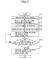
- FIG. 5 is a flowchart showing the operation of the destination floor indication device of an elevator in Embodiment 2 of the present invention expected when this destination floor indication device indicates destination floors. Because the operations in Steps S11 to S16 are the same as those in Steps S1 to S6 of Figure 3 in the Embodiment 1, the descriptions thereof are omitted.
- Step S16 when there is a destination floor at which the car has arrived or an added destination floor, the operation proceeds to Step S17.
- Step S 17 a screen including a destination floor at which a car has arrived or an added destination floor is indicated. And a destination floor at which a car has arrived or an added destination floor is indicated by a method different from the ordinary indication 11 for a given time. After that, the operation of the destination floor indication device 3 is finished, and the operation returns to START.
- one screen including a destination floor at which a car has arrived or an added destination floor is indicated on the indication section 4 for a given time. For this reason, it becomes easier for the user to perceive a destination floor at which a car has arrived or an added destination floor. Also a destination floor at which a car has arrived or an added destination floor is indicated on the indication section 4 by a method different from the ordinary indication 11. For this reason, it becomes easier for the user to perceive a destination floor at which a car has arrived or an added destination floor.
- the destination floor indication device of an elevator in the present invention can be applied to an elevator in which a destination floor indication device is provided in a hall or a car of the elevator.
Landscapes
- Indicating And Signalling Devices For Elevators (AREA)
- Elevator Control (AREA)
Applications Claiming Priority (1)
| Application Number | Priority Date | Filing Date | Title |
|---|---|---|---|
| PCT/JP2008/061966 WO2010001466A1 (fr) | 2008-07-02 | 2008-07-02 | Dispositif d’affichage d’étage de destination pour ascenseur |
Publications (2)
| Publication Number | Publication Date |
|---|---|
| EP2292545A1 true EP2292545A1 (fr) | 2011-03-09 |
| EP2292545A4 EP2292545A4 (fr) | 2014-01-22 |
Family
ID=41465582
Family Applications (1)
| Application Number | Title | Priority Date | Filing Date |
|---|---|---|---|
| EP08777769.4A Withdrawn EP2292545A4 (fr) | 2008-07-02 | 2008-07-02 | Dispositif d affichage d étage de destination pour ascenseur |
Country Status (6)
| Country | Link |
|---|---|
| US (1) | US8403113B2 (fr) |
| EP (1) | EP2292545A4 (fr) |
| JP (1) | JPWO2010001466A1 (fr) |
| KR (2) | KR20100135792A (fr) |
| CN (1) | CN102015507B (fr) |
| WO (1) | WO2010001466A1 (fr) |
Families Citing this family (22)
| Publication number | Priority date | Publication date | Assignee | Title |
|---|---|---|---|---|
| US9622389B1 (en) * | 2007-06-14 | 2017-04-11 | Switch, Ltd. | Electronic equipment data center and server co-location facility configurations and method of using the same |
| US9788455B1 (en) | 2007-06-14 | 2017-10-10 | Switch, Ltd. | Electronic equipment data center or co-location facility designs and methods of making and using the same |
| US8523643B1 (en) | 2007-06-14 | 2013-09-03 | Switch Communications Group LLC | Electronic equipment data center or co-location facility designs and methods of making and using the same |
| US11452242B2 (en) | 2007-06-14 | 2022-09-20 | Switch, Ltd. | Air handling unit with a canopy thereover for use with a data center and method of using the same |
| US9693486B1 (en) | 2007-06-14 | 2017-06-27 | Switch, Ltd. | Air handling unit with a canopy thereover for use with a data center and method of using the same |
| US9823715B1 (en) | 2007-06-14 | 2017-11-21 | Switch, Ltd. | Data center air handling unit including uninterruptable cooling fan with weighted rotor and method of using the same |
| US10028415B1 (en) | 2007-06-14 | 2018-07-17 | Switch, Ltd. | Electronic equipment data center and server co-location facility configurations and method of using the same |
| CN102317190A (zh) * | 2009-02-18 | 2012-01-11 | 三菱电机株式会社 | 电梯系统 |
| EP2407409B1 (fr) * | 2009-03-10 | 2018-09-05 | Mitsubishi Electric Corporation | Indicateur d'étages de destination de cage |
| JP5494805B2 (ja) * | 2010-06-30 | 2014-05-21 | 三菱電機株式会社 | エレベーターの監視装置 |
| US12087412B1 (en) | 2011-04-25 | 2024-09-10 | Zeus Data Solutions, Inc. | Electronic identification of healthcare patients |
| KR101617559B1 (ko) * | 2011-11-28 | 2016-05-02 | 미쓰비시덴키 가부시키가이샤 | 엘리베이터 시스템 |
| KR101304171B1 (ko) * | 2011-12-16 | 2013-09-09 | 박영진 | 엘리베이터 조작 상황 인지 시스템 |
| CN102556788A (zh) * | 2012-02-03 | 2012-07-11 | 上海新时达电气股份有限公司 | 电梯预报信息显示器及其显示方法 |
| DE112012007232T5 (de) * | 2012-12-17 | 2015-09-24 | Mitsubishi Electric Corporation | Aufzuganzeige-Steuervorrichtung |
| US9198331B2 (en) | 2013-03-15 | 2015-11-24 | Switch, Ltd. | Data center facility design configuration |
| CN104671019B (zh) * | 2013-11-28 | 2017-03-22 | 上海三菱电梯有限公司 | 电梯的目的楼层显示装置及显示方法 |
| JP5844423B2 (ja) * | 2014-06-18 | 2016-01-13 | 東芝エレベータ株式会社 | エレベータの乗りかご表示制御方法およびエレベータの乗りかご表示制御装置 |
| US20180077819A1 (en) | 2016-09-14 | 2018-03-15 | Switch, Ltd. | Ventilation and air flow control |
| JP6841377B2 (ja) * | 2018-03-14 | 2021-03-10 | 三菱電機株式会社 | エレベーターの情報表示装置、エレベーターシステムおよびエレベーターの情報表示方法 |
| KR102290752B1 (ko) * | 2020-12-04 | 2021-08-17 | 지성철 | 엘리베이터 제어 시스템 |
| JP7665506B2 (ja) * | 2021-12-22 | 2025-04-21 | 株式会社日立ビルシステム | エレベーターシステム |
Family Cites Families (18)
| Publication number | Priority date | Publication date | Assignee | Title |
|---|---|---|---|---|
| KR900001962B1 (ko) * | 1985-10-30 | 1990-03-27 | 미쓰비시전기 주식회사 | 엘리베이터의 표시제어장치 |
| JPH01288584A (ja) * | 1988-05-16 | 1989-11-20 | Mitsubishi Electric Corp | エレベータ用タッチパネル式呼釦装置 |
| JP2510746B2 (ja) | 1990-02-20 | 1996-06-26 | 三菱電機株式会社 | エレベ―タ―の表示灯制御装置 |
| JP3322906B2 (ja) | 1992-06-30 | 2002-09-09 | 昭和電工株式会社 | 熱交換器及びその製造方法 |
| JPH0859108A (ja) * | 1994-08-24 | 1996-03-05 | Toshiba Corp | エレベータの呼び登録装置 |
| CN1175998C (zh) * | 2000-06-16 | 2004-11-17 | 三菱电机株式会社 | 电梯操作盘 |
| US6508334B1 (en) * | 2000-06-21 | 2003-01-21 | Mitsubishi Denki Kabushiki Kaisha | Elevator destination registering apparatus for displaying route to a destination point |
| FI112792B (fi) * | 2001-08-14 | 2004-01-15 | Kone Corp | Hissin matkustajalle informatiivinen kerrosnumeronäyttö kerroksesa ja korissa |
| KR100617379B1 (ko) * | 2002-04-12 | 2006-08-29 | 미쓰비시덴키 가부시키가이샤 | 엘리베이터의 표시시스템 및 표시방법 |
| FI112793B (fi) * | 2002-04-22 | 2004-01-15 | Kone Corp | Matkustajien opastusjärjestelmä sekä näyttöväline |
| JP2003335469A (ja) * | 2002-05-17 | 2003-11-25 | Toshiba Elevator Co Ltd | エレベータの表示装置 |
| US7207422B2 (en) * | 2003-04-01 | 2007-04-24 | Mitsubishi Denki Kabushiki Kaisha | Elevator call recording device |
| AU2003279191B2 (en) * | 2003-10-08 | 2010-04-01 | Otis Elevator Company | Elevator traffic control |
| JP2005162344A (ja) * | 2003-11-28 | 2005-06-23 | Mitsubishi Electric Corp | 呼び登録装置及び呼び登録方法 |
| JPWO2005077803A1 (ja) * | 2004-02-13 | 2007-08-23 | 三菱電機株式会社 | エレベータの呼び登録装置 |
| WO2005105643A1 (fr) * | 2004-04-30 | 2005-11-10 | Mitsubishi Denki Kabushiki Kaisha | Indicateur d’etage de destination d’ascenseur |
| WO2006025096A1 (fr) * | 2004-08-30 | 2006-03-09 | Mitsubishi Denki Kabushiki Kaisha | Enregistreur de l'étage de destination pour un ascenseur |
| CN101573283A (zh) * | 2007-02-26 | 2009-11-04 | 三菱电机株式会社 | 电梯的目标楼层显示装置 |
-
2008
- 2008-07-02 WO PCT/JP2008/061966 patent/WO2010001466A1/fr not_active Ceased
- 2008-07-02 US US12/937,475 patent/US8403113B2/en not_active Expired - Fee Related
- 2008-07-02 JP JP2010518852A patent/JPWO2010001466A1/ja active Pending
- 2008-07-02 KR KR1020107022709A patent/KR20100135792A/ko not_active Ceased
- 2008-07-02 KR KR1020127025502A patent/KR101224727B1/ko not_active Expired - Fee Related
- 2008-07-02 EP EP08777769.4A patent/EP2292545A4/fr not_active Withdrawn
- 2008-07-02 CN CN200880128952.4A patent/CN102015507B/zh not_active Expired - Fee Related
Also Published As
| Publication number | Publication date |
|---|---|
| US8403113B2 (en) | 2013-03-26 |
| US20110031071A1 (en) | 2011-02-10 |
| KR20120127521A (ko) | 2012-11-21 |
| WO2010001466A1 (fr) | 2010-01-07 |
| CN102015507A (zh) | 2011-04-13 |
| KR101224727B1 (ko) | 2013-01-21 |
| KR20100135792A (ko) | 2010-12-27 |
| CN102015507B (zh) | 2014-07-02 |
| EP2292545A4 (fr) | 2014-01-22 |
| JPWO2010001466A1 (ja) | 2011-12-15 |
Similar Documents
| Publication | Publication Date | Title |
|---|---|---|
| EP2292545A1 (fr) | Dispositif d affichage d étage de destination pour ascenseur | |
| JP2008262544A (ja) | オン・スクリーン・ディスプレイ制御システム及びその操作方法 | |
| EP2141107B1 (fr) | Système d'ascenseur | |
| CN103064645A (zh) | 显示方法和电子设备 | |
| US8157059B2 (en) | Destination floor indication device of elevator | |
| JP5375947B2 (ja) | かご行先階表示装置 | |
| JP2009091099A (ja) | エレベータ | |
| US20100188425A1 (en) | Mode-changeover device | |
| JP2009137684A (ja) | エレベータの制御装置 | |
| US20200180904A1 (en) | Car operation panel, elevator system and display method of car operation panel | |
| KR20130064323A (ko) | 엘리베이터의 행선층 예약장치 및 그 제어방법 | |
| EP3809058B1 (fr) | Dispositif de gestion de climatiseur, et procédé de génération d'image d'écran pour gérer un climatiseur | |
| JP2010100230A (ja) | 車両用情報表示装置 | |
| JP2005162465A (ja) | エレベーター操作盤 | |
| KR101361380B1 (ko) | 엘리베이터의 표시 제어 장치 | |
| JP5505958B2 (ja) | エレベータシステムの表示制御装置 | |
| JP2002311931A (ja) | マルチモニタシステム | |
| CN111061211A (zh) | 用于工程机械的监控系统及其控制方法 | |
| JP2013195808A (ja) | 投影装置 | |
| JP2012030909A (ja) | 乗り場表示装置及びエレベータ | |
| JP6518622B2 (ja) | 表示装置、情報処理装置、画像処理装置および画像形成装置 | |
| JP2013140492A (ja) | 表示装置、情報処理装置、画像処理装置および画像形成装置 | |
| JP2013109180A (ja) | プロジェクタおよび画像投射システム | |
| JP5357535B2 (ja) | 表示装置および表示方法 | |
| JPH04168482A (ja) | ウィンドウ表示方式 |
Legal Events
| Date | Code | Title | Description |
|---|---|---|---|
| PUAI | Public reference made under article 153(3) epc to a published international application that has entered the european phase |
Free format text: ORIGINAL CODE: 0009012 |
|
| 17P | Request for examination filed |
Effective date: 20101007 |
|
| AK | Designated contracting states |
Kind code of ref document: A1 Designated state(s): AT BE BG CH CY CZ DE DK EE ES FI FR GB GR HR HU IE IS IT LI LT LU LV MC MT NL NO PL PT RO SE SI SK TR |
|
| AX | Request for extension of the european patent |
Extension state: AL BA MK RS |
|
| DAX | Request for extension of the european patent (deleted) | ||
| A4 | Supplementary search report drawn up and despatched |
Effective date: 20140103 |
|
| RIC1 | Information provided on ipc code assigned before grant |
Ipc: B66B 3/02 20060101AFI20131218BHEP |
|
| STAA | Information on the status of an ep patent application or granted ep patent |
Free format text: STATUS: THE APPLICATION HAS BEEN WITHDRAWN |
|
| 18W | Application withdrawn |
Effective date: 20140902 |