EP2292559B1 - Zementstaubaufbereitung - Google Patents
Zementstaubaufbereitung Download PDFInfo
- Publication number
- EP2292559B1 EP2292559B1 EP09010293.0A EP09010293A EP2292559B1 EP 2292559 B1 EP2292559 B1 EP 2292559B1 EP 09010293 A EP09010293 A EP 09010293A EP 2292559 B1 EP2292559 B1 EP 2292559B1
- Authority
- EP
- European Patent Office
- Prior art keywords
- evaporation crystallization
- solution
- stage
- hot
- cold
- Prior art date
- Legal status (The legal status is an assumption and is not a legal conclusion. Google has not performed a legal analysis and makes no representation as to the accuracy of the status listed.)
- Not-in-force
Links
- 239000004568 cement Substances 0.000 title claims description 7
- 239000000428 dust Substances 0.000 title description 2
- 238000002360 preparation method Methods 0.000 title description 2
- WCUXLLCKKVVCTQ-UHFFFAOYSA-M Potassium chloride Chemical compound [Cl-].[K+] WCUXLLCKKVVCTQ-UHFFFAOYSA-M 0.000 claims description 89
- FAPWRFPIFSIZLT-UHFFFAOYSA-M Sodium chloride Chemical compound [Na+].[Cl-] FAPWRFPIFSIZLT-UHFFFAOYSA-M 0.000 claims description 79
- 235000002639 sodium chloride Nutrition 0.000 claims description 57
- 238000002425 crystallisation Methods 0.000 claims description 54
- 230000008025 crystallization Effects 0.000 claims description 54
- 238000001704 evaporation Methods 0.000 claims description 54
- 230000008020 evaporation Effects 0.000 claims description 51
- 239000001103 potassium chloride Substances 0.000 claims description 45
- 235000011164 potassium chloride Nutrition 0.000 claims description 45
- 239000011780 sodium chloride Substances 0.000 claims description 40
- 239000000243 solution Substances 0.000 claims description 32
- 238000000034 method Methods 0.000 claims description 22
- OTYBMLCTZGSZBG-UHFFFAOYSA-L potassium sulfate Chemical compound [K+].[K+].[O-]S([O-])(=O)=O OTYBMLCTZGSZBG-UHFFFAOYSA-L 0.000 claims description 10
- 229910052939 potassium sulfate Inorganic materials 0.000 claims description 10
- 235000011151 potassium sulphates Nutrition 0.000 claims description 9
- XLYOFNOQVPJJNP-UHFFFAOYSA-N water Substances O XLYOFNOQVPJJNP-UHFFFAOYSA-N 0.000 claims description 7
- 238000009835 boiling Methods 0.000 claims description 6
- 238000001816 cooling Methods 0.000 claims description 4
- 238000011084 recovery Methods 0.000 claims description 4
- 238000007906 compression Methods 0.000 claims description 3
- 230000006835 compression Effects 0.000 claims description 3
- 239000003637 basic solution Substances 0.000 claims 4
- 238000010438 heat treatment Methods 0.000 claims 1
- 238000001556 precipitation Methods 0.000 claims 1
- 150000003839 salts Chemical class 0.000 description 17
- 239000012045 crude solution Substances 0.000 description 11
- 238000000926 separation method Methods 0.000 description 9
- 239000010802 sludge Substances 0.000 description 8
- 239000007864 aqueous solution Substances 0.000 description 7
- 239000000126 substance Substances 0.000 description 7
- 239000002244 precipitate Substances 0.000 description 5
- 238000001035 drying Methods 0.000 description 4
- 239000003344 environmental pollutant Substances 0.000 description 4
- 239000003337 fertilizer Substances 0.000 description 4
- 238000005469 granulation Methods 0.000 description 4
- 230000003179 granulation Effects 0.000 description 4
- 231100000719 pollutant Toxicity 0.000 description 4
- 239000007787 solid Substances 0.000 description 3
- 239000002562 thickening agent Substances 0.000 description 3
- 239000002245 particle Substances 0.000 description 2
- 239000002243 precursor Substances 0.000 description 2
- 229920006395 saturated elastomer Polymers 0.000 description 2
- 239000002904 solvent Substances 0.000 description 2
- 239000000725 suspension Substances 0.000 description 2
- 239000000498 cooling water Substances 0.000 description 1
- 238000004090 dissolution Methods 0.000 description 1
- 238000001914 filtration Methods 0.000 description 1
- 239000008394 flocculating agent Substances 0.000 description 1
- 230000014509 gene expression Effects 0.000 description 1
- 239000012535 impurity Substances 0.000 description 1
- 239000001120 potassium sulphate Substances 0.000 description 1
- 230000001376 precipitating effect Effects 0.000 description 1
- 239000000376 reactant Substances 0.000 description 1
- -1 salts potassium chloride Chemical class 0.000 description 1
- 238000005406 washing Methods 0.000 description 1
Images

Classifications
-
- C—CHEMISTRY; METALLURGY
- C01—INORGANIC CHEMISTRY
- C01D—COMPOUNDS OF ALKALI METALS, i.e. LITHIUM, SODIUM, POTASSIUM, RUBIDIUM, CAESIUM, OR FRANCIUM
- C01D3/00—Halides of sodium, potassium or alkali metals in general
- C01D3/04—Chlorides
- C01D3/08—Preparation by working up natural or industrial salt mixtures or siliceous minerals
-
- C—CHEMISTRY; METALLURGY
- C01—INORGANIC CHEMISTRY
- C01D—COMPOUNDS OF ALKALI METALS, i.e. LITHIUM, SODIUM, POTASSIUM, RUBIDIUM, CAESIUM, OR FRANCIUM
- C01D3/00—Halides of sodium, potassium or alkali metals in general
- C01D3/14—Purification
-
- C—CHEMISTRY; METALLURGY
- C01—INORGANIC CHEMISTRY
- C01D—COMPOUNDS OF ALKALI METALS, i.e. LITHIUM, SODIUM, POTASSIUM, RUBIDIUM, CAESIUM, OR FRANCIUM
- C01D5/00—Sulfates or sulfites of sodium, potassium or alkali metals in general
- C01D5/16—Purification
-
- C—CHEMISTRY; METALLURGY
- C04—CEMENTS; CONCRETE; ARTIFICIAL STONE; CERAMICS; REFRACTORIES
- C04B—LIME, MAGNESIA; SLAG; CEMENTS; COMPOSITIONS THEREOF, e.g. MORTARS, CONCRETE OR LIKE BUILDING MATERIALS; ARTIFICIAL STONE; CERAMICS; REFRACTORIES; TREATMENT OF NATURAL STONE
- C04B7/00—Hydraulic cements
- C04B7/36—Manufacture of hydraulic cements in general
- C04B7/60—Methods for eliminating alkali metals or compounds thereof, e.g. from the raw materials or during the burning process; methods for eliminating other harmful components
Definitions
- the invention relates to a process for the recovery of potassium chloride and sodium chloride and potassium sulfate from a crude aqueous solution obtained by treating particulate cement dusts containing these salts with water.
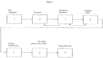
- step 1 the substance is delivered and, if necessary, temporarily stored in silos and then further processed according to step 2.
- step 2 the substances are released.
- the solvent used is usually water.
- the particles size in step 2 is expediently less than 1 mm.
- step 3 the sludge is separated by means of suitable separation devices, such as filter presses or vacuum belt filter with expediently simultaneous washing of the sludge by condensate from the subsequent plants.
- the separated solution is transported with residual amounts of the substance to thickeners. At this point, the separation of the residual sludge from the solution.
- a flocculant may find application.
- the thickened suspension from the thickener is returned to step 2 while the clear solution is being processed.
- the sludge (desalted substance) can be reused after drainage.
- step 4 if desired and / or required, one or more of the salts is converted into a different salt form by addition of reaction auxiliaries so that as few different salts as possible or salts are formed which can be readily separated from one another in the further steps.
- This resulting reactants can after concentration by z. B. thickener before or returned to step 3, to finally dispose of them with the main amount of sludge or separate with appropriate facilities to dispose of and sell. The remaining clear solution is processed further.
- step 5 - if desired - the pollutants are precipitated by adding appropriate precipitants.
- the suspension is placed in a separator, where appropriate, with the aid of flocculants, the enlargement of the finest pollutant particles are carried out, so that they can be recycled either before the filtration of the main amount of sludge in step 3 or separated with the sludge.
- a separator where appropriate, with the aid of flocculants, the enlargement of the finest pollutant particles are carried out, so that they can be recycled either before the filtration of the main amount of sludge in step 3 or separated with the sludge.
- There may also be a separate separation of the pollutants by, for example, filter presses or vacuum belt filters for separate disposal.
- step 6 the salt-containing and most extensive pollutant-free solution obtained in step 5 is then further processed. At this point, the present invention attacks.
- a solution which is processed by the process according to the invention contains as salts potassium chloride and sodium chloride and potassium sulfate.
- the crude solution is fed to a hot evaporation crystallization unit 1 (compare number 1 in Figure 3). There, the crude solution is evaporated to just below the saturation of potassium chloride, precipitating salt, which is separated. This salt is primarily K 2 SO 4 . In other words, it is evaporated without the saturation limit being exceeded by neither potassium chloride nor sodium chloride.
- the potassium sulfate can be sold after separation, drying and any granulation as fertilizers, for example.
- the evaporation in the evaporating crystallization unit 1 takes place at higher temperatures, which will be discussed in more detail below.
- stage Aa The starting solution obtained after the pretreatment is fed in stage Aa) to a cold evaporation crystallization unit 2, in which the solution is concentrated without exceeding the saturation limit of sodium chloride. In this case, potassium chloride crystallizes out and is separated off.
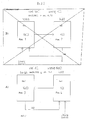
- stage Aa) is shown in the attached figure 2 by the position 4.
- a partial stream from the cold evaporation crystallization unit 2 is conveyed into the hot evaporation crystallization unit 3 in accordance with stage Ab).
- stage Ab is evaporated without the saturation limit of potassium chloride is exceeded.
- sodium chloride crystallizes out and is separated off.
- the effluent or the solution leaving this stage Ab) is either discarded or preferably returned to the cold evaporation crystallization unit 2 (number 2 in figure 3 or position 4 in figure 2).
- the hot evaporation crystallization unit 3 is designated in position 2 with the position 3.
- the temperature in the cold evaporation crystallization unit 2 (number 2 in FIG. 3 or position 4 in FIG. 2) is at least 10 ° C. lower than in the hot evaporation crystallization unit 3.
- the temperature difference between the cold evaporation crystallization unit 2 and the hot evaporation crystallization unit 3 and thus between the process stages Aa) on the one hand and Ab) on the other hand is at least 10 ° C and preferably at least 30 ° C, for example 10, 11, 12, 13, 14 , 15, 15, 17, 18, 19, 20, 21, 22, 23, 24, 25, 26, 27, 28, 29, 30, 31, 32, 33, 34, 35, 36, 37, 38, 39 , 40, 41, 42, 43, 44, 45, 46, 47, 48, 49, 50, 51, 52, 53, 54, 55, 56, 57, 58, ° C, etc.
- the concentration in the cold evaporating crystallization unit 2 takes place at low temperatures of 0 ° C. to 69 ° C., preferably at 20-69 ° C. and particularly preferably at 30-60 ° C.
- range data include all narrower ranges contained and also all conceivable individual values and stand in particular for 0, 1, 2, 3, 4, 5, 6, 7, 8, 9, 10, 11, 12, 13, 14, 15, 16, 17, 18, 19, 20, 21, 22, 23, 24, 25, 26, 27, 28, 29, 30, 31, 32, 33, 34, 35, 36, 37, 38, 39, 40, 41, 42, 43, 44, 45, 46, 47, 48, 49, 50, 51, 52, 53, 54, 55, 56, 57, 58, 59, 60 61, 62, 63, 64, 65, 66, 67, 68 and 69 ° C. These temperatures are referred to herein as low temperatures.
- the vacuum prevailing in the cold evaporation crystallization unit 2 is selected and adjusted so that evaporation crystallization can take place.
- the question of how low the temperature can be chosen at this concentration depends on various factors, e.g. B. the temperature of the available cooling water. or the available cooling devices.
- the evaporation in the hot evaporation crystallization unit 3 takes place at 70 ° C. up to the boiling point of the solution, preferably at 90 ° C. to the boiling point of the solution and thus, for example, at 70, 71, 72, 73, 74, 75, 76, 77, 78, 79, 80, 81, 82, 83, 84, 85, 86, 87, 88, 89, 90, 91, 92, 93, 94, 95, 96, 97, 98, 99, 100, 101, 102, 103, 104, 105 ° C, etc.
- the upper temperature value or boiling point of course depends on the pressure prevailing in the system. The higher the proportion of dissolved substances and / or the pressure, the higher the boiling point of the respective solution.
- the total amount of water can be removed.
- all the sodium chloride and potassium chloride entering the system may be precipitated.
- stage Ab is preferably carried out in one stage at high temperatures, while the cold stage Aa) can also be carried out in several stages. If the inlet concentrations permit, the plants can also be connected in series in terms of steam in order to save energy.
- the stage Ab can be carried out in one or more stages and, if appropriate, can be switched in series, provided the inlet concentrations permit this. If necessary, the vapor compression can also be provided for the hot evaporation stage.
- the evaporation crystallization in the hot evaporation crystallization unit 1 and 3 is preferably carried out either multi-stage or with thermal or mechanical vapor compression.
- Concentration in the cold evaporative crystallizer 2 at low temperatures usually requires the application of a vacuum to remove the solvent / water at the selected temperature and to obtain evaporation and thus concentration. For this reason, it is also spoken of an evaporative crystallization plant here.
- the concentration is therefore preferably carried out as a vacuum cooling stage.
- the hot evaporation crystallization unit 3 (number 3 in FIG. 3 or position 1 or 3 in FIG. 2), with a suitable concentration ratio of KCl to NaCl, it may be sufficient to heat only to precipitate or crystallize NaCl.
- an aqueous solution which has been obtained by treating particulate cement dusts and thus by dissolution, etc., is referred to as an aqueous solution.
- this aqueous solution is fed to the process precursor in the evaporative crystallization unit 1, it is referred to as a crude solution.
- the solution fed to stage Aa) is called the starting solution.
- the resulting solution is either discarded in the subsequent process stage Ac) and / or recycled to the stage Ab).
- the salts obtained during the process according to the invention may, if necessary, be compacted in order to obtain a better sales revenue.
- the crude solution is - as shown in Figure 3 - in a hot Eindampftkristallisationsstrom 1 (represents a preferred precursor) is evaporated to just below the saturation of potassium chloride.
- the evaporation thus takes place without the saturation limit of potassium chloride being exceeded.
- work is carried out at a high temperature, since at a high temperature the lowest possible potassium sulfate saturation at high potassium chloride concentration in the solution exists.
- the saturation limit of potassium chloride is about 33.5%, while the saturation limit of potassium sulfate is about 1.85%.
- the influence of the sodium chloride is disregarded in this consideration due to the small amount in the crude solution and the resulting low influence on the solubility.
- temperature 104 ° C can be called here.
- the crude solution is introduced in an amount of about 7.8 m 3 / h in the Eindampfkristallisationsstrom 1.
- the concentration takes place here at low temperature, since at a low temperature as high as possible saturation of sodium chloride at the lowest possible potassium chloride saturation prevails.
- temperature here 51 ° C can be called.
- a pressure of about 100 mbar is set.
- the solution obtained from the hot evaporation crystallization plant 1 (number 1 in FIG. 3) is introduced into the cold evaporation crystallization plant 2 in an amount of 3.3 m 3 / h (number 2 in FIG. 3 or position 4 in FIG Picture 2).
- the inventive step Ab is performed.
- the solution is further evaporated.
- higher temperature eg, 104 ° C
- sodium chloride saturation and lower sodium chloride saturation results in higher potassium chloride saturation and lower sodium chloride saturation (in other words, the saturation limit of potassium chloride is higher or greater than the saturation limit of sodium chloride at a higher temperature
- sodium chloride precipitates, in which the solution is evaporated to just below the saturation limit of potassium chloride at high temperature.
- the resulting sodium chloride can be sold after separation, possible drying and granulation, for example, as road salt.
- this preferably means NaCl / KCl ⁇ 0.72. Is however of little NaCl and much KCl or a low NaCl content and a high KCl content the Speaking, this preferably means NaCl / KCl ⁇ 1.4 (refers to the weight).
Landscapes
- Chemical & Material Sciences (AREA)
- Organic Chemistry (AREA)
- Engineering & Computer Science (AREA)
- Materials Engineering (AREA)
- Inorganic Chemistry (AREA)
- Ceramic Engineering (AREA)
- Toxicology (AREA)
- Public Health (AREA)
- Environmental & Geological Engineering (AREA)
- Health & Medical Sciences (AREA)
- Structural Engineering (AREA)
- Life Sciences & Earth Sciences (AREA)
- General Life Sciences & Earth Sciences (AREA)
- Geochemistry & Mineralogy (AREA)
- Geology (AREA)
- Fertilizers (AREA)
Description
- Die Erfindung betrifft ein Verfahren zur Rückgewinnung von Kaliumchlorid und Natriumchlorid sowie Kaliumsulfat aus einer wässrigen Rohlösung, die durch Behandeln von partikelförmigen Zementstäuben, welche diese Salze enthalten, mit Wasser erhalten wurde.
- Für die Aufbereitung salzhaltiger Feststoffe und zur Rückgewinnung verschiedener Salze aus einer wässrigen Lösung, die durch Behandeln von derartigen partikelförmigen Feststoffen mit Wasser erhalten wurde, können die verschiedensten Verfahren eingesetzt werden.
- Aus der
US 140 217 3 A ist ein Verfahren zur Gewinnung von Kaliumchlorid einer wässrigen, hauptsächlich Kaliumchlorid und Natriumchlorid enthaltenden Waschlösung von Zementstäuben bekannt. Bei diesem Verfahren wird die Lösung bis fast zum Sättigungspunkt von Kaliumchlorid verdampft. Dabei fällt Natriumchlorid aus, das abfiltriert wird. Die verbleibende Lösung wird einer Kristallisationsstufe zugeführt, in der Kaliumchlorid ausfällt. Eine ähnliche Auftrennung von Natriumchlorid und Kaliumchlorid offenbart auch dieJP 11 2009121 A - Die bei einer derartigen Aufbereitung bzw. Rückgewinnung durchgeführten Verfahrensschritte sind in dem anliegenden Bild 1 schematisch dargelegt.
- Im Schritt 1 wird dabei der Stoff angeliefert und erforderlichenfalls in Silos zwischengelagert und dann gemäß Schritt 2 weiterverarbeitet.
- Im Schritt 2 werden die Stoffe verlöst. Als Lösungsmittel wird üblicherweise Wasser eingesetzt. Dabei gehen die in den Stoffen enthaltenen bzw. daran anhaftenden Salze und auch ein Großteil der Schadstoffe in Lösung. Erforderlichenfalls können die Feststoffe noch mechanisch verkleinert werden. Die Partikelgröße im Schritt 2 beträgt zweckmäßigerweise weniger als 1 mm.
- Im Schritt 3 wird der Schlamm mit Hilfe geeigneter Abtrenneinrichtungen, beispielsweise Filterpressen oder Vakuumbandfilter bei zweckmäßigerweise gleichzeitigem Waschen des Schlammes durch Kondensat aus den Folgeanlagen abgetrennt. Die abgetrennte Lösung wird mit Restanteilen des Stoffes zu Eindickapparaten transportiert. An dieser Stelle erfolgt die Abtrennung des Restschlammes aus der Lösung. Gewünschtenfalls kann ein Flockungsmittel Anwendung finden.
- Die eingedickte Suspension aus dem Eindickapparat wird zurück zum Schritt 2 gefördert, während die klare Lösung weiterverarbeitet wird. Der Schlamm (entsalzter Stoff) kann nach der Entwässerung weiterverwendet werden.
- Im Schritt 4 werden - sofern erwünscht und/oder erforderlich - eine oder mehrere der Salze durch Zugabe von Reaktionshilfsmitteln in eine andere Salzform überführt, so dass möglichst wenige unterschiedliche Salze entstehen bzw. Salze entstehen, die in den weiteren Schritten gut voneinander getrennt werden können. Hierbei anfallende Reaktionsstoffe können nach der Aufkonzentrierung durch z. B. Eindicker vor- oder zu Schritt 3 zurückgeführt werden, um sie schlussendlich mit der Hauptschlammmenge zu entsorgen oder mit entsprechenden Einrichtungen abzutrennen, zu entsorgen und zu verkaufen. Die verbleibende klare Lösung wird weiterverarbeitet.
- Im Schritt 5 werden - sofern gewünscht - die Schadstoffe durch Zugabe von entsprechenden Fällmitteln ausgefällt. Aus dem Reaktor wird die Suspension in eine Abscheideeinrichtung gegeben, wo gegebenenfalls mit Hilfe von Flockungsmitteln die Vergrößerung der feinsten Schadstoffpartikel erfolgt, so dass diese entweder vor die Filtration der Hauptschlammmenge im Schritt 3 zurückgeführt werden können oder mit dem Schlamm abgetrennt werden. Es kann auch eine separate Abtrennung der Schadstoffe durch beispielsweise Filterpressen oder Vakuumbandfilter zur getrennten Entsorgung erfolgen.
- Die bisher geschilderten Schritte sind üblicher Art. Die erforderlichen Verfahrensparameter können je nach Erfordernis festgelegt und gewählt werden. Dies erfolgt insbesondere in Abhängigkeit von der Art und dem Zustand der Zementstäube, von denen bzw. aus denen die hier Rede stehenden Salze erhalten wurden.
- Im Schritt 6 wird nun die im Schritt 5 erhaltene salzhaltige und weitestgehende schadstofffreie Lösung weiterverarbeitet. An dieser Stelle greift die vorliegende Erfindung an.
- Aufgabe der vorliegenden Erfindung ist es, aus einer die hier in Rede stehenden Salze enthaltenden wässrigen Lösung diese Salze in möglichst reiner sowie möglichst verkaufsfähiger bzw. wiedereinsetzbarer Form zurückzugewinnen, damit die zurückgewonnen Salze den am Markt üblichen Anforderungen entsprechen und verwertet werden können.
- Gelöst wird diese Aufgabe durch die Lehre der Ansprüche.
- Eine Lösung, die nach dem erfindungsgemäßen Verfahren verarbeitet wird, enthält als Salze Kaliumchlorid und Natriumchlorid sowie Kaliumsulfat.
- Bevor die hier mit Aa) und Ab) beschriebenen Verfahrensstufen durchgeführt werden, wird eine Art Vorbehandlung durchgeführt.
- Als Rohlösung wird im Rahmen der vorliegenden Unterlagen im Übrigen eine solche bezeichnet, die nach dem oben beschriebenen Schritt 5 erhalten wurde.
- Bei der Vorbehandlung wird die Rohlösung einer heißen Eindampfkristallisationsanlage 1 (man vergleiche Nummer 1 im Bild 3) zugeführt wird. Dort wird die Rohlösung bis knapp unter die Sättigung von Kaliumchlorid eingedampft, wobei Salz ausfällt, das abgetrennt wird. Bei diesem Salz handelt es sich primär um K2SO4. Mit anderen Worten, es wird eingedampft, ohne dass die Sättigungsgrenze weder von Kaliumchlorid noch von Natriumchlorid überschritten wird.
- Das Kaliumsulfat kann nach Abtrennung, Trocknung und eventueller Granulierung als beispielsweise Düngemittel verkauft werden.
- Die Eindampfung in der Eindampfkristallisationsanlage 1 erfolgt bei höheren Temperaturen, worauf nachstehend noch näher eingegangen wird.
- Die oben genannte heiße Eindampfkristallisationsanlage 1 und auch die weiter unten näher erläuterten kalte Eindampfkristallisationsanlage 2 sowie die heiße Eindampfkristallisationsanlage 3 sind in dem beiliegenden Bild 3 schematisch dargestellt.
- Die nach der Vorbehandlung erhalten Ausgangslösung wird in der Stufe Aa) einer kalten Eindampfkristallisationsanlage 2 zugeführt, in der die Lösung aufkonzentriert wird, ohne dass die Sättigungsgrenze von Natriumchlorid überschritten wird. Dabei kristallisiert Kaliumchlorid aus und wird abgetrennt. Diese Stufe Aa) ist im beiliegenden Bild 2 durch die Position 4 dargestellt.
- Ein Teilstrom aus der kalten Eindampfkristallisationsanlage 2 wird in die heiße Eindampfkristallisationsanlage 3 gemäß Stufe Ab) gefördert. In dieser Stufe Ab) wird eingedampft, ohne dass die Sättigungsgrenze von Kaliumchlorid überschritten wird. Dabei kristallisiert Natriumchlorid aus und wird abgetrennt. Der Ablauf bzw. die aus dieser Stufe Ab) austretende Lösung wird entweder verworfen oder vorzugsweise wieder in die kalte Eindampfkristallisationsanlage 2 (Nummer 2 in Bild 3 bzw. Position 4 in Bild 2) zurückgeführt.
- Die heiße Eindampfkristallisationsanlage 3 ist im Bild 2 mit der Position 3 bezeichnet. Die Temperatur in der kalten Eindampfkristallisationsanlage 2 (Nummer 2 in Bild 3 bzw. Position 4 im Bild 2) um mindestens 10°C niedriger als in der heißen Eindampfkristallisationsanlage 3.
- Mit anderen Worten, der Temperaturunterschied zwischen der kalten Eindampfkristallisationsanlage 2 und der heißen Eindampfkristallisationsanlage 3 und somit zwischen den Verfahrensstufen Aa) einerseits und Ab) andererseits beträgt mindestens 10 °C und vorzugsweise mindestens 30°C, beispielsweise 10, 11, 12 , 13, 14, 15, 15, 17, 18, 19, 20, 21, 22, 23, 24, 25, 26, 27, 28, 29, 30, 31, 32, 33, 34, 35, 36, 37, 38, 39, 40, 41, 42, 43, 44, 45, 46, 47, 48, 49, 50, 51, 52, 53, 54, 55, 56, 57, 58, °C usw.
- Die Aufkonzentrierung in der kalten Eindampfkristallisationsanlage 2 (Nummer 2 im Bild 3 bzw. Position 4 im Bild 2) erfolgt bei niedrigen Temperaturen von 0 °C bis 69 °C, vorzugsweise bei 20-69 °C und insbesondere bevorzugt bei 30 - 60 °C Diese Bereichsangaben umfassen alle enthaltenen engeren Bereiche und auch alle denkbaren Einzelwerte und stehen insbesondere für 0, 1, 2,3, 4, 5, 6, 7, 8, 9, 10, 11, 12, 13, 14, 15, 16, 17, 18, 19, 20, 21, 22, 23, 24, 25, 26, 27, 28, 29, 30, 31, 32, 33, 34, 35, 36, 37, 38, 39, 40, 41, 42, 43, 44, 45, 46, 47, 48, 49, 50, 51, 52, 53, 54, 55, 56, 57, 58, 59, 60 61, 62, 63, 64, 65, 66, 67, 68 und 69°C. Diese Temperaturen werden im Rahmen der vorliegenden Unterlagen als niedrige Temperaturen bezeichnet.
- Entsprechend der Temperatur wird natürlich das in der kalten Eindampfkristallisationsanlage 2 herrschende Vakuum gewählt und eingestellt, damit eine Eindampfkristallisation erfolgen kann.
- Die Frage, wie niedrig die Temperatur bei dieser Aufkonzentration gewählt werden kann, hängt von verschiedenen Faktoren ab, z. B. der Temperatur des zur Verfügung stehenden Kühlwassers. bzw. der zur Verfügung stehenden Kühleinrichtungen.
- Die Eindampfung in der heißen Eindampfkristallisationsanlage 3 (Nummer 3 im Bild 3 bzw. Position 3 im Bild 2) erfolgt bei 70°C bis zum Siedepunkt der Lösung, vorzugsweise bei 90 °C bis zum Siedepunkt der Lösung und somit beispielsweise bei 70, 71, 72, 73, 74, 75, 76, 77, 78, 79, 80, 81, 82, 83, 84, 85, 86, 87, 88, 89, 90, 91, 92, 93, 94, 95, 96, 97, 98, 99, 100, 101, 102, 103, 104, 105 °C usw. Der obere Temperaturwert bzw. Siedepunkt hängt natürlich von dem in der Anlage herrschenden Druck ab. Je höher der Anteil der gelösten Stoffe und/oder der Druck ist, desto höher liegt der Siedepunkt der jeweiligen Lösung.
- Diese Temperaturen werden im Rahmen der vorliegenden Unterlagen als hohe Temperaturen angesehen. Auch in diesem Falle sind alle engeren Bereiche umfasst und somit offenbart. Gleiches gilt auch für die zwischen den Bereichsgrenzen liegenden Einzelwerte, die damit umfasst und offenbart sind. Bevorzugte Einzelwerte sind somit beispielsweise 90, 91, 92, 93, 94, 95, 96, 97, 98, 99, 100, 101, 102, 103 und 104 °C usw.
- Durch den geschilderten Kreislauf zwischen der heißen Stufe und der kalten Stufe kann die gesamte Wassermenge entfernt werden. Zudem kann das gesamte in der Anlage eintretende Natriumchlorid und Kaliumchlorid (abzüglich eventueller Abschlämmungen aufgrund anderer Verunreinigungen) ausgefällt werden.
- Die Stufe Ab) wird bei hohen Temperaturen vorzugsweise einstufig ausgeführt, während die kalte Stufe Aa) auch mehrstufig ausgeführt werden kann. Falls es die Eintrittskonzentrationen zulassen, können die Anlagen aus Energieeinsparungsgründen auch dampfmäßig hintereinander geschaltet werden.
- Durch den dargestellten Kreislauf kann die gesamte Natriumchlorid- und Kaliumchloridmenge auskristallisiert werden. Um Dampfenergie einzusparen, kann die Stufe Ab) ein- oder mehrstufig durchgeführt und eventuell energetisch hintereinander geschaltet werden, sofern dies die Eintrittskonzentrationen zulassen. Für die heiße Eindampfstufe kann gegebenenfalls auch die Brüdenverdichtung vorgesehen werden.
- Die Eindampfkristallisation in der heißen Eindampfkristallisationsanlage 1 und 3 wird vorzugsweise entweder mehrstufig oder mit thermischer oder mechanischer Brüdenverdichtung durchgeführt.
- Eine Aufkonzentration in der kalten Eindampfkristallisationsanlage 2 bei niedrigen Temperaturen macht es üblicherweise erforderlich, ein Vakuum anzulegen, um das Lösungsmittel/Wasser bei der gewählten Temperatur zu entfernen und eine Eindampfung und somit eine Aufkonzentration zu erhalten. Aus diesem Grund wird hier auch von einer Eindampfkristallisationsanlage gesprochen. Die Aufkonzentration erfolgt daher vorzugsweise als Vakuum-Kühlstufe.
- Wird jedoch eine Lösung mit höherer Temperatur in die kalte Eindampfkristallisationsanlage 2 (Nummer 2 im Bild 3 bzw. Position 2 oder 4 im Bild 2) eingeleitet oder im Kreislauf zurückgeleitet, dann kann es ausreichend sein, dort bei einem entsprechenden Konzentrationsverhältnis von KCl zu NaCl lediglich eine reine Kühlung vorzunehmen, da auch in diesem Fall eine Aufkonzentration bezogen auf die Sättigungsgrenze erfolgt.
- In der heißen Eindampfkristallisationsanlage 3 (Nummer 3 im Bild 3 bzw. Position 1 oder 3 im Bild 2) kann es bei einem geeigneten Konzentrationsverhältnis von KCl zu NaCl ausreichend sein, nur zu erwärmen, um NaCl auszufällen bzw. zu kristallisieren.
- Im Rahmen der vorliegenden Unterlagen wird aus Zwecken einer besseren Darstellbarkeit eine wässrige Lösung, die durch Behandeln von partikelförmigen Zementstäuben und somit durch Verlösen etc. erhalten wurde, als wässrige Lösung bezeichnet.
- Wird diese wässrige Lösung der Verfahrens-Vorstufe in der Eindampfkristallisationsanlage 1 zugeführt, dann wird sie als Rohlösung bezeichnet.
- Die der Stufe Aa) zugeführte Lösung wird als Ausgangslösung bezeichnet.
- Nach Durchführung der kalten Verfahrensvariante Aa) wird die sich ergebende Lösung in der sich anschließenden Verfahrensstufe Ac) entweder verworfen und/oder zur Stufe Ab) im Kreislauf zurückgeführt. Die während des erfindungsgemäßen Verfahrens erhaltenen Salze können, soweit erforderlich, kompaktiert werden, um einen besseren Verkaufserlös zu erzielen.
- Die in den vorliegenden Unterlagen im Zusammenhang mit den Begriffen "Eindampfkristallisation", "Stufe", "Verfahrensstufe" etc verwendeten Ausdrücke "heiß" und kalt" dienen lediglich zur leichteren Unterscheidung der Begriffe. Die erfindungsgemäß zur Anwendung gebrachten Temperaturen sind separat erläutert.
- Die Erfindung wird im folgenden anhand einer Rohlösung mit einem niedrigen Natriumchloridgehalt und einem hohen Kaliumchloridgehalt unter Bezug auf das beiliegenden Bild 3 näher erläutert. Diese Rohlösung wurde durch Behandeln eines typischen Zementstaubes erhalten. Die Rohlösung besaß folgende Gehalte (sofern nichts anderes angegeben ist, beziehen sich die %-Angaben auf Gewichtsprozent): Kaliumsulfat 5,7 %, Natriumchlorid 1,1 %, Kaliumchlorid 15,8 %.
- Die Rohlösung wird - wie im Bild 3 gezeigt - in einer heißen Eindampfkristallisationsanlage 1 (stellt eine bevorzugte Vorstufe dar) bis knapp unter die Sättigung von Kaliumchlorid eingedampft. Die Eindampfung erfolgt somit ohne dass die Sättigungsgrenze von Kaliumchlorid überschritten wird. Vorzugsweise wird bei einer hohen Temperatur gearbeitet, da bei einer hohen Temperatur eine möglichst geringe Kaliumsulfat-Sättigung bei hoher Kaliumchlorid-Konzentration in der Lösung existiert. So beträgt beispielsweise bei ca. 100 °C die Sättigungsgrenze von Kaliumchlorid ca. 33,5 %, während die Sättigungs-grenze von Kaliumsulfat ca. 1,85 % beträgt. Der Einfluss des Natriumchlorids bleibt aufgrund der geringen Menge in der Rohlösung und dem daraus resultierenden geringen Einflüssen auf die Löslichkeit bei dieser Betrachtung unberücksichtigt. Als beispielhafte Temperatur kann hier 104 °C genannt werden.
- Die Rohlösung wird dabei in einer Menge von ca. 7,8 m3/h in die Eindampfkristallisationsanlage 1 eingeleitet.
- Durch diesen Verfahrensschritt können aus der Rohlösung über 80 % des vorhandenen Kaliumsulfats auskristallisiert werden, das nach Abtrennung, Trocknung und evtl. Granulierung einer gewerblichen Verwendung zugeführt werden kann, beispielsweise als Düngemittel.
- Die aus der heißen Eindampfkristallisationsanlage 1 (Nummer 1 im Bild 3) ablaufende Lösung (K2SO4 = 2 %, NaCl = 2,3 %, KCl = 33,5 %) gelangt in die nachfolgende kalte Eindampfkristallisationsanlage 2 (Nummer 2 im Bild 3 bzw. Position 4 im Bild 2), in der weiter eingedampft wird, ohne dass die Natriumchlorid-Sättigung überschritten wird. In dieser kalten Eindampfkristallisationsanlage 2 (Nummer 2 im Bild 3 bzw. Position 4 im Bild 2) wird die erfindungsgemäße Stufe Aa) durchgeführt.
- Die Aufkonzentrierung erfolgt hierbei bei niedriger Temperatur, da bei einer niedrigen Temperatur eine möglichst hohe Natriumchlorid-Sättigung bei möglichst niedriger Kaliumchlorid-Sättigung herrscht. Als beispielhafte Temperatur kann hier 51 °C genannt werden. Bei dieser Temperatur wird ein Druck von ca. 100 mbar eingestellt.
- In dieser kalten Stufe Aa) fällt zusammen mit dem Kaliumchlorid auch das noch lösliche Kaliumsulfat aus. Das entstehende Salz kann nach Abtrennung, Trocknung und eventuell Granulierung als hochwertiges Düngemittel verkauft werden, da es die für ein solches Düngemittel erforderlichen Reinheitsanforderungen erfüllt.
- Die aus der heißen Eindampfkristallisationsanlage 1 (Nummer 1 im Bild 3) erhaltene Lösung wird im Übrigen bei dem hier beschriebenem Beispiel in einer Menge von 3,3 m3/h in die kalte Eindampfkristallisationsanlage 2 (Nummer 2 im Bild 3 bzw. Position 4 im Bild 2) überführt.
- Die aus der kalten Eindampfkristallisationsanlage 2 (Nummer 2 im Bild 3 bzw. Position 4 im Bild 2) austretende kalte Lösung (K2SO4 = 0,2 %, NaCl = 18,1 %, KCl = 15 %) wird in eine weitere heiße Eindampfkristallisationsanlage 3 (Nummer 3 im Bild 3 bzw. Position 3 im Bild 2) überführt, die bei hohen Temperaturen arbeitet. In dieser heißen Eindampfkristallisationsanlage 3 wird die erfindungsgemäße Stufe Ab) durchgeführt.
- In der heißen Eindampfkristallisationsanlage 3 (Nummer 3 im Bild 3 bzw. Position 3 im Bild 2) wird die Lösung weiter eingedampft. Da sich bei einer höheren Temperatur (z. B. 104 °C) eine höhere Kaliumchlorid-Sättigung und eine niedrigere Natriumchlorid-Sättigung ergibt (mit anderen Worten: die Sättigungsgrenze von Kaliumchlorid ist bei einer höheren Temperatur höher bzw. größer als die Sättigungsgrenze von Natriumchlorid), fällt in dieser Stufe Natriumchlorid aus, in dem die Lösung bis knapp unter die Sättigungsgrenze des Kaliumchlorids bei hoher Temperatur eingedampft wird. Das entstehende Natriumchlorid kann nach Abtrennung, eventueller Trocknung und Granulierung beispielsweise als Streusalz verkauft werden.
- In der heißen Eindampfkristallisationsanlage 3 (Nummer 3 im Bild 3 bzw. Position 3 im Bild 2) ergibt sich eine Abstoßlösung, die an Natriumchlorid gesättigt und an Kaliumchlorid nahezu gesättigt ist (K2SO4 = 0,2 %, NaCl = 16,7 %, KCl = 17,1 %). Diese Lösung wird zurück in die kalte Eindampfkristallisationsanlage 2 (Nummer 2 im Bild 3 bzw. Position 4 im Bild 2) geführt, worin aufgrund der geringen Löslichkeit von Kaliumchlorid bei tieferer Temperatur weiteres Kaliumchlorid ausfällt. Bei entsprechender Einstellung dieses Kreislaufes zwischen Eindampfkristallisationsanlage 2 und 3 kann bei Verdampfung des Restwassers eine komplette Trennung von Kaliumchlorid und Natriumchlorid erzielt werden. Wenn erfindungsgemäß von viel NaCl und wenig KCl bzw. einem hohen NaCl-Gehalt und einem niedrigen KCl-Gehalt die Rede ist, bedeutet dies vorzugsweise NaCl/KCl ≥ 0,72. Ist hingegen von wenig NaCl und viel KCl bzw. einem niedrigen NaCl-Gehalt und einem hohen KCl-Gehalt die Rede ist, bedeutet dies vorzugsweise NaCl/KCl ≤ 1,4 (bezieht sich auf das Gewicht).
Definitionen Eindampfkristallisationsanlage 1 = heiß K2SO4 Auskristallisation = Nummer 1 im Bild 3 Eindampfkristallisationsanlage 2 = kalt KCl Auskristallisation Stufe Aa) = Nummer 2 in Bild 3 = Position 4 im Bild 2 kalte Stufe Eindampfkristallisationsanlage 3 = heiß NaCl Auskristallisation Stufe Ab) = Nummer 3 in Bild 3 = Position 3 im Bild 2 heiße Stufe
Claims (7)
- Verfahren zur Rückgewinnung von Kaliumchlorid und Natriumchlorid sowie Kaliumsulfat aus einer wässrigen Rohlösung, die durch Behandeln von Zementstäuben mit Wasser erhalten wurde,
dadurch gekennzeichnet, dass
die Rohlösung einer heißen Eindampfkristallisationsanlage (1), die bei hohen Temperaturen von 70°C bis zum Siedepunkt der Lösung betrieben wird, zugeführt wird und dort eingedampft wird, ohne dass die Sättigungsgrenze weder von Kaliumchlorid noch von Natriumchlorid überschritten wird, wobei ausgefallenes K2SO4 abgetrennt wird,
die nach der Abtrennung erhaltene AusgangslösungAa) einer kalten, bei niedrigen Temperaturen von 0°C bis 69 °C betriebenen Eindampfkristallisationsanlage (2) zugeführt wird, in der die Lösung aufkonzentriert wird, ohne dass die Sättigungsgrenze von Natriumchlorid überschritten wird, und das ausgefallene KCl abgetrennt wird,Ab) die aus der Stufe Aa) Lösung austretende Lösung einer heißen, bei hohen Temperaturen von 70°C bis zum Siedepunkt der Lösung betriebenen Eindampfkristallisationsanlage (3) zugeführt und dort eingedampft wird, ohne dass die Sättigungsgrenze von Kaliumchlorid überschritten wird, und das ausfallende NaCl abgetrennt wird und,Ac) die aus der Stufe Ab) austretende Lösung verworfen und/oder wieder in die Stufe Aa) zurückgeführt wird,dass die Temperatur in der kalten Eindampfkristallisationsanlage (2) um mindestens 10°C niedriger ist als in der heißen Eindampfkristallisationsanlage (3).
und - Verfahren nach Anspruch 1,
dadurch gekennzeichnet, dass
eine Rohlösung mit einem Gewichtsverhältnis von NaCl zu KCl ≤ 1,4 eingesetzt wird. - Verfahren nach Anspruch 1 oder 2,
dadurch gekennzeichnet, dass
die niedrigen Temperaturen 20°C bis 69 °C, insbesondere 30°C bis 60°C, weiterhin insbesondere 51°C und die hohen Temperaturen 104°C betragen. - Verfahren nach einem der vorhergehenden Ansprüche,
dadurch gekennzeichnet, dass
die Eindampfkristallisation in den heißen Eindampfkristallisationsanlage (1) und (3) mehrstufig oder mit thermischer oder mechanischer Brüdenverdichtung durchgeführt wird. - Verfahren nach einem der vorhergehenden Ansprüche,
dadurch gekennzeichnet, dass
die Eindampfkristallisation in der kalten Eindampfkristallisationsanlage (2) als Vakuum-Kühlstufe durchgeführt wird. - Verfahren nach einem der vorhergehenden Ansprüche,
dadurch gekennzeichnet, dass
die Temperatur in der kalten Eindampfkristallisationsanlage (2) um mindestens 30°C niedriger ist als in der heißen Eindampfkristallisationsanlage (3). - Verfahren nach einem der vorhergehenden Ansprüche,
dadurch gekennzeichnet, dass
die Eindampfkristallisation in der heißen Eindampfkristallisationsanlage (3) nur durch Erwärmen erreicht wird.
Priority Applications (1)
| Application Number | Priority Date | Filing Date | Title |
|---|---|---|---|
| EP09010293.0A EP2292559B1 (de) | 2009-08-10 | 2009-08-10 | Zementstaubaufbereitung |
Applications Claiming Priority (1)
| Application Number | Priority Date | Filing Date | Title |
|---|---|---|---|
| EP09010293.0A EP2292559B1 (de) | 2009-08-10 | 2009-08-10 | Zementstaubaufbereitung |
Publications (2)
| Publication Number | Publication Date |
|---|---|
| EP2292559A1 EP2292559A1 (de) | 2011-03-09 |
| EP2292559B1 true EP2292559B1 (de) | 2017-07-19 |
Family
ID=41172443
Family Applications (1)
| Application Number | Title | Priority Date | Filing Date |
|---|---|---|---|
| EP09010293.0A Not-in-force EP2292559B1 (de) | 2009-08-10 | 2009-08-10 | Zementstaubaufbereitung |
Country Status (1)
| Country | Link |
|---|---|
| EP (1) | EP2292559B1 (de) |
Families Citing this family (1)
| Publication number | Priority date | Publication date | Assignee | Title |
|---|---|---|---|---|
| DE102013110854B4 (de) * | 2013-10-01 | 2019-01-24 | Terrawater Gmbh | Verfahren zur getrennten Abscheidung von Natriumchlorid und Kaliumchlorid aus einem wässrigen Medium |
Family Cites Families (6)
| Publication number | Priority date | Publication date | Assignee | Title |
|---|---|---|---|---|
| US1402173A (en) * | 1919-10-22 | 1922-01-03 | Int Precipitation Co | Process for obtaining potassium chloride |
| DE1592009B1 (de) * | 1965-10-01 | 1971-06-24 | Montedison Spa | Verfahren zur abtrennung von natriumchlorid aus mischungen mit kalisalzen |
| DE2801705A1 (de) * | 1978-01-16 | 1979-07-19 | Metallgesellschaft Ag | Verfahren zur gewinnung von kaliumchlorid |
| JPH11209121A (ja) * | 1998-01-26 | 1999-08-03 | Hitachi Ltd | ミネラル成分の濃縮晶析装置 |
| JP4789461B2 (ja) * | 2004-12-24 | 2011-10-12 | 株式会社ササクラ | 混合塩の分別方法および分別装置 |
| RU2448046C2 (ru) * | 2007-03-06 | 2012-04-20 | Потасио Рио Колорадо С.А. | Способ отделения хлорида калия и хлорида натрия |
-
2009
- 2009-08-10 EP EP09010293.0A patent/EP2292559B1/de not_active Not-in-force
Non-Patent Citations (1)
| Title |
|---|
| None * |
Also Published As
| Publication number | Publication date |
|---|---|
| EP2292559A1 (de) | 2011-03-09 |
Similar Documents
| Publication | Publication Date | Title |
|---|---|---|
| DE69403968T2 (de) | Verfahren und einrichtung zur regenerierung von fluechtigen saeuren | |
| DE2850785A1 (de) | Verfahren zur gewinnung der inhaltsstoffe aus salzwasser | |
| EP2681158B1 (de) | Aufbereitung von rohsolen aus entsalzungsanlagen | |
| DE102008007154A1 (de) | Verfahren zur Herstellung eines grobkörnigen Ammoniumsulfat-Produkts durch Kristllisation und Anlage zur Durchführung des Verfahrens | |
| EP0142018A1 (de) | Verfahren und Vorrichtung zur Abwasserreinigung | |
| WO2014090973A1 (de) | Verfahren und anlage zur aufbereitung und verarbeitung von wässern | |
| EP1318105A1 (de) | Verfahren und Vorrichtung zur Entfernung von Ammonium aus Abwässern und zur Wertstoffgewinnung | |
| DE1592064C3 (de) | Kontinuierlich betriebenes Verfahren zur Gewinnung von Aluminiumchlorid-Hexahydrat | |
| DE102016112944A1 (de) | Verfahren für die Herstellung von Melamin mit Trennung und Rückgewinnung von CO2 und NH3 von hoher Reinheit | |
| DE1173074B (de) | Verfahren zum Aufarbeiten der bei der Titandioxyd-Herstellung nach dem Schwefel-saeureaufschluss-Verfahren anfallenden Hydrolysesaeuren | |
| EP0003065B1 (de) | Verfahren zur Gewinnung von Kaliumchlorid | |
| EP2292559A1 (de) | Zementstaubaufbereitung | |
| EP0363838B1 (de) | Verfahren und Vorrichtung zur Gewinnung reinen Wassers und im Wasser gelöster Stoffe | |
| DE2358409C2 (de) | Verfahren zur Reinigung wässriger Natriumcitrat-Lösungen | |
| EP2586519A1 (de) | Aufarbeitung von belastetem Abwasser aus der Produktion von Pflanzenschutzmitteln | |
| DE602006000880T2 (de) | Verfahren und Vorrichtung zur Nassoxidierung von Schlamm | |
| DE19541558A1 (de) | Verfahren zur Reinigung von Lithiumchlorid-Lösungen | |
| DE102009018956A1 (de) | Verfahren zur Herstellung von Kaliumsulfat aus Bittern | |
| EP3898520A1 (de) | Verfahren zur herstellung von ammoniummetawolframat | |
| EP2938424B1 (de) | Verfahren und vorrichtung zur aufbereitung einer mit kohlendioxid verunreinigten aminosäuresalzlösung | |
| DE2415872A1 (de) | Verfahren zur verminderung des gehaltes an organischen verbindungen in der aluminatlauge bei der tonerdeherstellung nach dem bayer-verfahren | |
| DE3938915C1 (de) | ||
| DE102020109697B4 (de) | Verfahren und Anlage zur prozessintegrierten Behandlung und Verwertung von Bypassstaub | |
| DE112015006221T5 (de) | Verfahren zur Verarbeitung von polymineralischen Kaliumerzen unter Gewinnung von Kaliumsulfat | |
| DE3728320C2 (de) | Verfahren und Vorrichtung zur Aufkonzentration von Lösungen bis zum Feststoffaustrag |
Legal Events
| Date | Code | Title | Description |
|---|---|---|---|
| PUAI | Public reference made under article 153(3) epc to a published international application that has entered the european phase |
Free format text: ORIGINAL CODE: 0009012 |
|
| AK | Designated contracting states |
Kind code of ref document: A1 Designated state(s): AT BE BG CH CY CZ DE DK EE ES FI FR GB GR HR HU IE IS IT LI LT LU LV MC MK MT NL NO PL PT RO SE SI SK SM TR |
|
| AX | Request for extension of the european patent |
Extension state: AL BA RS |
|
| 17P | Request for examination filed |
Effective date: 20110516 |
|
| 17Q | First examination report despatched |
Effective date: 20110620 |
|
| GRAP | Despatch of communication of intention to grant a patent |
Free format text: ORIGINAL CODE: EPIDOSNIGR1 |
|
| INTG | Intention to grant announced |
Effective date: 20170301 |
|
| GRAS | Grant fee paid |
Free format text: ORIGINAL CODE: EPIDOSNIGR3 |
|
| GRAA | (expected) grant |
Free format text: ORIGINAL CODE: 0009210 |
|
| AK | Designated contracting states |
Kind code of ref document: B1 Designated state(s): AT BE BG CH CY CZ DE DK EE ES FI FR GB GR HR HU IE IS IT LI LT LU LV MC MK MT NL NO PL PT RO SE SI SK SM TR |
|
| REG | Reference to a national code |
Ref country code: GB Ref legal event code: FG4D Free format text: NOT ENGLISH |
|
| REG | Reference to a national code |
Ref country code: CH Ref legal event code: EP |
|
| REG | Reference to a national code |
Ref country code: IE Ref legal event code: FG4D Free format text: LANGUAGE OF EP DOCUMENT: GERMAN |
|
| REG | Reference to a national code |
Ref country code: CH Ref legal event code: NV Representative=s name: TROESCH SCHEIDEGGER WERNER AG, CH Ref country code: AT Ref legal event code: REF Ref document number: 910201 Country of ref document: AT Kind code of ref document: T Effective date: 20170815 |
|
| REG | Reference to a national code |
Ref country code: DE Ref legal event code: R096 Ref document number: 502009014163 Country of ref document: DE |
|
| REG | Reference to a national code |
Ref country code: FR Ref legal event code: PLFP Year of fee payment: 9 |
|
| PGFP | Annual fee paid to national office [announced via postgrant information from national office to epo] |
Ref country code: FR Payment date: 20170914 Year of fee payment: 9 Ref country code: CH Payment date: 20170831 Year of fee payment: 9 Ref country code: GB Payment date: 20170830 Year of fee payment: 9 |
|
| REG | Reference to a national code |
Ref country code: NL Ref legal event code: MP Effective date: 20170719 |
|
| PGFP | Annual fee paid to national office [announced via postgrant information from national office to epo] |
Ref country code: AT Payment date: 20170907 Year of fee payment: 9 |
|
| REG | Reference to a national code |
Ref country code: LT Ref legal event code: MG4D |
|
| PG25 | Lapsed in a contracting state [announced via postgrant information from national office to epo] |
Ref country code: HR Free format text: LAPSE BECAUSE OF FAILURE TO SUBMIT A TRANSLATION OF THE DESCRIPTION OR TO PAY THE FEE WITHIN THE PRESCRIBED TIME-LIMIT Effective date: 20170719 Ref country code: NL Free format text: LAPSE BECAUSE OF FAILURE TO SUBMIT A TRANSLATION OF THE DESCRIPTION OR TO PAY THE FEE WITHIN THE PRESCRIBED TIME-LIMIT Effective date: 20170719 Ref country code: LT Free format text: LAPSE BECAUSE OF FAILURE TO SUBMIT A TRANSLATION OF THE DESCRIPTION OR TO PAY THE FEE WITHIN THE PRESCRIBED TIME-LIMIT Effective date: 20170719 Ref country code: FI Free format text: LAPSE BECAUSE OF FAILURE TO SUBMIT A TRANSLATION OF THE DESCRIPTION OR TO PAY THE FEE WITHIN THE PRESCRIBED TIME-LIMIT Effective date: 20170719 Ref country code: NO Free format text: LAPSE BECAUSE OF FAILURE TO SUBMIT A TRANSLATION OF THE DESCRIPTION OR TO PAY THE FEE WITHIN THE PRESCRIBED TIME-LIMIT Effective date: 20171019 Ref country code: SE Free format text: LAPSE BECAUSE OF FAILURE TO SUBMIT A TRANSLATION OF THE DESCRIPTION OR TO PAY THE FEE WITHIN THE PRESCRIBED TIME-LIMIT Effective date: 20170719 |
|
| PG25 | Lapsed in a contracting state [announced via postgrant information from national office to epo] |
Ref country code: BG Free format text: LAPSE BECAUSE OF FAILURE TO SUBMIT A TRANSLATION OF THE DESCRIPTION OR TO PAY THE FEE WITHIN THE PRESCRIBED TIME-LIMIT Effective date: 20171019 Ref country code: IS Free format text: LAPSE BECAUSE OF FAILURE TO SUBMIT A TRANSLATION OF THE DESCRIPTION OR TO PAY THE FEE WITHIN THE PRESCRIBED TIME-LIMIT Effective date: 20171119 Ref country code: PL Free format text: LAPSE BECAUSE OF FAILURE TO SUBMIT A TRANSLATION OF THE DESCRIPTION OR TO PAY THE FEE WITHIN THE PRESCRIBED TIME-LIMIT Effective date: 20170719 Ref country code: LV Free format text: LAPSE BECAUSE OF FAILURE TO SUBMIT A TRANSLATION OF THE DESCRIPTION OR TO PAY THE FEE WITHIN THE PRESCRIBED TIME-LIMIT Effective date: 20170719 Ref country code: ES Free format text: LAPSE BECAUSE OF FAILURE TO SUBMIT A TRANSLATION OF THE DESCRIPTION OR TO PAY THE FEE WITHIN THE PRESCRIBED TIME-LIMIT Effective date: 20170719 Ref country code: GR Free format text: LAPSE BECAUSE OF FAILURE TO SUBMIT A TRANSLATION OF THE DESCRIPTION OR TO PAY THE FEE WITHIN THE PRESCRIBED TIME-LIMIT Effective date: 20171020 |
|
| REG | Reference to a national code |
Ref country code: DE Ref legal event code: R097 Ref document number: 502009014163 Country of ref document: DE |
|
| PG25 | Lapsed in a contracting state [announced via postgrant information from national office to epo] |
Ref country code: RO Free format text: LAPSE BECAUSE OF FAILURE TO SUBMIT A TRANSLATION OF THE DESCRIPTION OR TO PAY THE FEE WITHIN THE PRESCRIBED TIME-LIMIT Effective date: 20170719 Ref country code: CZ Free format text: LAPSE BECAUSE OF FAILURE TO SUBMIT A TRANSLATION OF THE DESCRIPTION OR TO PAY THE FEE WITHIN THE PRESCRIBED TIME-LIMIT Effective date: 20170719 Ref country code: MC Free format text: LAPSE BECAUSE OF FAILURE TO SUBMIT A TRANSLATION OF THE DESCRIPTION OR TO PAY THE FEE WITHIN THE PRESCRIBED TIME-LIMIT Effective date: 20170719 Ref country code: DK Free format text: LAPSE BECAUSE OF FAILURE TO SUBMIT A TRANSLATION OF THE DESCRIPTION OR TO PAY THE FEE WITHIN THE PRESCRIBED TIME-LIMIT Effective date: 20170719 |
|
| PLBE | No opposition filed within time limit |
Free format text: ORIGINAL CODE: 0009261 |
|
| STAA | Information on the status of an ep patent application or granted ep patent |
Free format text: STATUS: NO OPPOSITION FILED WITHIN TIME LIMIT |
|
| REG | Reference to a national code |
Ref country code: IE Ref legal event code: MM4A |
|
| PG25 | Lapsed in a contracting state [announced via postgrant information from national office to epo] |
Ref country code: SK Free format text: LAPSE BECAUSE OF FAILURE TO SUBMIT A TRANSLATION OF THE DESCRIPTION OR TO PAY THE FEE WITHIN THE PRESCRIBED TIME-LIMIT Effective date: 20170719 Ref country code: SM Free format text: LAPSE BECAUSE OF FAILURE TO SUBMIT A TRANSLATION OF THE DESCRIPTION OR TO PAY THE FEE WITHIN THE PRESCRIBED TIME-LIMIT Effective date: 20170719 Ref country code: EE Free format text: LAPSE BECAUSE OF FAILURE TO SUBMIT A TRANSLATION OF THE DESCRIPTION OR TO PAY THE FEE WITHIN THE PRESCRIBED TIME-LIMIT Effective date: 20170719 Ref country code: IT Free format text: LAPSE BECAUSE OF FAILURE TO SUBMIT A TRANSLATION OF THE DESCRIPTION OR TO PAY THE FEE WITHIN THE PRESCRIBED TIME-LIMIT Effective date: 20170719 |
|
| REG | Reference to a national code |
Ref country code: BE Ref legal event code: MM Effective date: 20170831 |
|
| 26N | No opposition filed |
Effective date: 20180420 |
|
| PG25 | Lapsed in a contracting state [announced via postgrant information from national office to epo] |
Ref country code: LU Free format text: LAPSE BECAUSE OF NON-PAYMENT OF DUE FEES Effective date: 20170810 |
|
| PG25 | Lapsed in a contracting state [announced via postgrant information from national office to epo] |
Ref country code: IE Free format text: LAPSE BECAUSE OF NON-PAYMENT OF DUE FEES Effective date: 20170810 |
|
| PG25 | Lapsed in a contracting state [announced via postgrant information from national office to epo] |
Ref country code: SI Free format text: LAPSE BECAUSE OF FAILURE TO SUBMIT A TRANSLATION OF THE DESCRIPTION OR TO PAY THE FEE WITHIN THE PRESCRIBED TIME-LIMIT Effective date: 20170719 Ref country code: BE Free format text: LAPSE BECAUSE OF NON-PAYMENT OF DUE FEES Effective date: 20170831 |
|
| PG25 | Lapsed in a contracting state [announced via postgrant information from national office to epo] |
Ref country code: MT Free format text: LAPSE BECAUSE OF FAILURE TO SUBMIT A TRANSLATION OF THE DESCRIPTION OR TO PAY THE FEE WITHIN THE PRESCRIBED TIME-LIMIT Effective date: 20170719 |
|
| REG | Reference to a national code |
Ref country code: CH Ref legal event code: PL |
|
| REG | Reference to a national code |
Ref country code: AT Ref legal event code: MM01 Ref document number: 910201 Country of ref document: AT Kind code of ref document: T Effective date: 20180810 |
|
| GBPC | Gb: european patent ceased through non-payment of renewal fee |
Effective date: 20180810 |
|
| PG25 | Lapsed in a contracting state [announced via postgrant information from national office to epo] |
Ref country code: AT Free format text: LAPSE BECAUSE OF NON-PAYMENT OF DUE FEES Effective date: 20180810 Ref country code: LI Free format text: LAPSE BECAUSE OF NON-PAYMENT OF DUE FEES Effective date: 20180831 Ref country code: CH Free format text: LAPSE BECAUSE OF NON-PAYMENT OF DUE FEES Effective date: 20180831 |
|
| PGFP | Annual fee paid to national office [announced via postgrant information from national office to epo] |
Ref country code: DE Payment date: 20190227 Year of fee payment: 10 |
|
| PG25 | Lapsed in a contracting state [announced via postgrant information from national office to epo] |
Ref country code: HU Free format text: LAPSE BECAUSE OF FAILURE TO SUBMIT A TRANSLATION OF THE DESCRIPTION OR TO PAY THE FEE WITHIN THE PRESCRIBED TIME-LIMIT; INVALID AB INITIO Effective date: 20090810 |
|
| PG25 | Lapsed in a contracting state [announced via postgrant information from national office to epo] |
Ref country code: FR Free format text: LAPSE BECAUSE OF NON-PAYMENT OF DUE FEES Effective date: 20180831 |
|
| PG25 | Lapsed in a contracting state [announced via postgrant information from national office to epo] |
Ref country code: GB Free format text: LAPSE BECAUSE OF NON-PAYMENT OF DUE FEES Effective date: 20180810 Ref country code: CY Free format text: LAPSE BECAUSE OF NON-PAYMENT OF DUE FEES Effective date: 20170719 |
|
| PG25 | Lapsed in a contracting state [announced via postgrant information from national office to epo] |
Ref country code: MK Free format text: LAPSE BECAUSE OF FAILURE TO SUBMIT A TRANSLATION OF THE DESCRIPTION OR TO PAY THE FEE WITHIN THE PRESCRIBED TIME-LIMIT Effective date: 20170719 |
|
| REG | Reference to a national code |
Ref country code: DE Ref legal event code: R119 Ref document number: 502009014163 Country of ref document: DE |
|
| PG25 | Lapsed in a contracting state [announced via postgrant information from national office to epo] |
Ref country code: TR Free format text: LAPSE BECAUSE OF FAILURE TO SUBMIT A TRANSLATION OF THE DESCRIPTION OR TO PAY THE FEE WITHIN THE PRESCRIBED TIME-LIMIT Effective date: 20170719 |
|
| PG25 | Lapsed in a contracting state [announced via postgrant information from national office to epo] |
Ref country code: PT Free format text: LAPSE BECAUSE OF FAILURE TO SUBMIT A TRANSLATION OF THE DESCRIPTION OR TO PAY THE FEE WITHIN THE PRESCRIBED TIME-LIMIT Effective date: 20170719 |
|
| PG25 | Lapsed in a contracting state [announced via postgrant information from national office to epo] |
Ref country code: DE Free format text: LAPSE BECAUSE OF NON-PAYMENT OF DUE FEES Effective date: 20200303 |