EP2292727A1 - Séquenceur en temps réel de molécules simples, analyseur d'acides nucléiques et procédé de séquençage en temps réel de molécules simples - Google Patents
Séquenceur en temps réel de molécules simples, analyseur d'acides nucléiques et procédé de séquençage en temps réel de molécules simples Download PDFInfo
- Publication number
- EP2292727A1 EP2292727A1 EP09770037A EP09770037A EP2292727A1 EP 2292727 A1 EP2292727 A1 EP 2292727A1 EP 09770037 A EP09770037 A EP 09770037A EP 09770037 A EP09770037 A EP 09770037A EP 2292727 A1 EP2292727 A1 EP 2292727A1
- Authority
- EP
- European Patent Office
- Prior art keywords
- reaction
- nucleic acid
- light
- real time
- single molecule
- Prior art date
- Legal status (The legal status is an assumption and is not a legal conclusion. Google has not performed a legal analysis and makes no representation as to the accuracy of the status listed.)
- Granted
Links
Images


Classifications
-
- C—CHEMISTRY; METALLURGY
- C12—BIOCHEMISTRY; BEER; SPIRITS; WINE; VINEGAR; MICROBIOLOGY; ENZYMOLOGY; MUTATION OR GENETIC ENGINEERING
- C12Q—MEASURING OR TESTING PROCESSES INVOLVING ENZYMES, NUCLEIC ACIDS OR MICROORGANISMS; COMPOSITIONS OR TEST PAPERS THEREFOR; PROCESSES OF PREPARING SUCH COMPOSITIONS; CONDITION-RESPONSIVE CONTROL IN MICROBIOLOGICAL OR ENZYMOLOGICAL PROCESSES
- C12Q1/00—Measuring or testing processes involving enzymes, nucleic acids or microorganisms; Compositions therefor; Processes of preparing such compositions
- C12Q1/68—Measuring or testing processes involving enzymes, nucleic acids or microorganisms; Compositions therefor; Processes of preparing such compositions involving nucleic acids
- C12Q1/6869—Methods for sequencing
- C12Q1/6874—Methods for sequencing involving nucleic acid arrays, e.g. sequencing by hybridisation
-
- B—PERFORMING OPERATIONS; TRANSPORTING
- B82—NANOTECHNOLOGY
- B82Y—SPECIFIC USES OR APPLICATIONS OF NANOSTRUCTURES; MEASUREMENT OR ANALYSIS OF NANOSTRUCTURES; MANUFACTURE OR TREATMENT OF NANOSTRUCTURES
- B82Y30/00—Nanotechnology for materials or surface science, e.g. nanocomposites
-
- G—PHYSICS
- G01—MEASURING; TESTING
- G01N—INVESTIGATING OR ANALYSING MATERIALS BY DETERMINING THEIR CHEMICAL OR PHYSICAL PROPERTIES
- G01N21/00—Investigating or analysing materials by the use of optical means, i.e. using sub-millimetre waves, infrared, visible or ultraviolet light
- G01N21/62—Systems in which the material investigated is excited whereby it emits light or causes a change in wavelength of the incident light
- G01N21/63—Systems in which the material investigated is excited whereby it emits light or causes a change in wavelength of the incident light optically excited
- G01N21/64—Fluorescence; Phosphorescence
- G01N21/645—Specially adapted constructive features of fluorimeters
- G01N21/648—Specially adapted constructive features of fluorimeters using evanescent coupling or surface plasmon coupling for the excitation of fluorescence
-
- B—PERFORMING OPERATIONS; TRANSPORTING
- B01—PHYSICAL OR CHEMICAL PROCESSES OR APPARATUS IN GENERAL
- B01J—CHEMICAL OR PHYSICAL PROCESSES, e.g. CATALYSIS OR COLLOID CHEMISTRY; THEIR RELEVANT APPARATUS
- B01J2219/00—Chemical, physical or physico-chemical processes in general; Their relevant apparatus
- B01J2219/00274—Sequential or parallel reactions; Apparatus and devices for combinatorial chemistry or for making arrays; Chemical library technology
- B01J2219/00277—Apparatus
- B01J2219/00497—Features relating to the solid phase supports
- B01J2219/00527—Sheets
- B01J2219/00529—DNA chips
-
- B—PERFORMING OPERATIONS; TRANSPORTING
- B01—PHYSICAL OR CHEMICAL PROCESSES OR APPARATUS IN GENERAL
- B01J—CHEMICAL OR PHYSICAL PROCESSES, e.g. CATALYSIS OR COLLOID CHEMISTRY; THEIR RELEVANT APPARATUS
- B01J2219/00—Chemical, physical or physico-chemical processes in general; Their relevant apparatus
- B01J2219/00274—Sequential or parallel reactions; Apparatus and devices for combinatorial chemistry or for making arrays; Chemical library technology
- B01J2219/00583—Features relative to the processes being carried out
- B01J2219/00596—Solid-phase processes
-
- B—PERFORMING OPERATIONS; TRANSPORTING
- B01—PHYSICAL OR CHEMICAL PROCESSES OR APPARATUS IN GENERAL
- B01J—CHEMICAL OR PHYSICAL PROCESSES, e.g. CATALYSIS OR COLLOID CHEMISTRY; THEIR RELEVANT APPARATUS
- B01J2219/00—Chemical, physical or physico-chemical processes in general; Their relevant apparatus
- B01J2219/00274—Sequential or parallel reactions; Apparatus and devices for combinatorial chemistry or for making arrays; Chemical library technology
- B01J2219/00583—Features relative to the processes being carried out
- B01J2219/00603—Making arrays on substantially continuous surfaces
- B01J2219/00605—Making arrays on substantially continuous surfaces the compounds being directly bound or immobilised to solid supports
- B01J2219/00608—DNA chips
-
- B—PERFORMING OPERATIONS; TRANSPORTING
- B01—PHYSICAL OR CHEMICAL PROCESSES OR APPARATUS IN GENERAL
- B01J—CHEMICAL OR PHYSICAL PROCESSES, e.g. CATALYSIS OR COLLOID CHEMISTRY; THEIR RELEVANT APPARATUS
- B01J2219/00—Chemical, physical or physico-chemical processes in general; Their relevant apparatus
- B01J2219/00274—Sequential or parallel reactions; Apparatus and devices for combinatorial chemistry or for making arrays; Chemical library technology
- B01J2219/00709—Type of synthesis
- B01J2219/00711—Light-directed synthesis
-
- B—PERFORMING OPERATIONS; TRANSPORTING
- B01—PHYSICAL OR CHEMICAL PROCESSES OR APPARATUS IN GENERAL
- B01J—CHEMICAL OR PHYSICAL PROCESSES, e.g. CATALYSIS OR COLLOID CHEMISTRY; THEIR RELEVANT APPARATUS
- B01J2219/00—Chemical, physical or physico-chemical processes in general; Their relevant apparatus
- B01J2219/00274—Sequential or parallel reactions; Apparatus and devices for combinatorial chemistry or for making arrays; Chemical library technology
- B01J2219/00718—Type of compounds synthesised
- B01J2219/0072—Organic compounds
- B01J2219/00722—Nucleotides
-
- B—PERFORMING OPERATIONS; TRANSPORTING
- B01—PHYSICAL OR CHEMICAL PROCESSES OR APPARATUS IN GENERAL
- B01L—CHEMICAL OR PHYSICAL LABORATORY APPARATUS FOR GENERAL USE
- B01L3/00—Containers or dishes for laboratory use, e.g. laboratory glassware; Droppers
- B01L3/50—Containers for the purpose of retaining a material to be analysed, e.g. test tubes
- B01L3/502—Containers for the purpose of retaining a material to be analysed, e.g. test tubes with fluid transport, e.g. in multi-compartment structures
- B01L3/5027—Containers for the purpose of retaining a material to be analysed, e.g. test tubes with fluid transport, e.g. in multi-compartment structures by integrated microfluidic structures, i.e. dimensions of channels and chambers are such that surface tension forces are important, e.g. lab-on-a-chip
- B01L3/502707—Containers for the purpose of retaining a material to be analysed, e.g. test tubes with fluid transport, e.g. in multi-compartment structures by integrated microfluidic structures, i.e. dimensions of channels and chambers are such that surface tension forces are important, e.g. lab-on-a-chip characterised by the manufacture of the container or its components
Definitions
- the present invention relates to an analysis method for a nucleic acid sequence and an analyzer of the nucleic acid sequence. More specifically, the present invention relates to a method and a device to decode a base sequence of, for example, a nucleic acid such as DNA or RNA.
- a human genome plan where 3 billion dollars of budget has been spent from 1990 to 2005, enabled to read a part easiest to decode (93% of the whole parts) 2 to 3 years earlier than originally planned, and has left, as a property, a technology or a method required in decoding, as shown in the Non Patent Literature 1.
- Such technology has shown further improvement thereafter, and at present, genome decoding becomes possible in precision practically endurable in a cost of about 20 million dollars ($2 ⁇ 10 7 ).
- Decoding of a large scale base sequence in this high cost is still limited only by a special decoding center, or a research project obtained a high amount of budget.
- cost reduction in sequence determination will enable to handle much larger quantity of genome by many parties.
- Non Patent Literature 3 there have been commercialized already several next generation sequencers. These technologies have already attained 1/10 to 1/100 level cost as compared with conventional technology. In addition, number of bases measurable by one time analysis has attained an order of 10 9 . However, enhancement of these sequencers in view of cost has nearly saturated, and it is estimated that attainment of the "thousand dollars genome" by a device and a system already commercialized is difficult.
- next generation sequencers now available on the market are capable of decoding a base sequence of up to about 10 9 , however, they require running time of 2 to 3 days only for sequence decoding of a data volume as large as about 10 9 .
- sequence decoding on an individual basis to be a routine work, not only cost reduction but also high speed sequence decoding are necessary.
- the single molecule real time sequencing method carries out fluorescence detection in real time where base extension is carried out. Therefore, it is capable of carrying out base sequence decoding in dramatically high speed.
- amplification of a sample by PCR is not required, and thus dramatic cost reduction is also possible. Therefore, the single molecule real time sequencing method is one of the most promising technologies for attaining the "thousand dollars genome”.
- the Non Patent Literature 4 has disclosed one of the single molecule real time sequencing methods.
- a measurement method is adopted for energy fluorescence transfer to acceptor-nucleotide accompanying with the extension reaction of nucleic acid, by immobilization of polymerase modified with a donor fluorescence body on a substrate.
- a caged compound can be included.
- the caged compound is a generic term for one that modifies a biologically active molecule by a photodegradable protecting group to deactivate temporarily. It has a name of the "caged compound” to mean a molecule to have biological activity slept by putting it in a cage.
- the protecting group is dislocated only at the site irradiated in an instant of light irradiation, resulting in expression of original biological activity. That is, it becomes possible to control temporal and spatial dynamics of a chemical reaction by irradiation of light.
- the caged compound is used to prepare a pool of oligo nucleotides.
- this method uses a sequential reaction, and is a method for sequentially decomposing the caged compound bound to the terminal, accompanying with the reaction. Therefore, this method is not used for real time analysis.
- a target of this method is multi-molecules and not a single molecule.
- extension reaction fluorescence from a single molecule immobilized on a substrate is detected with a CCD camera through an objective lens.
- the objective lens has limited observable view, it cannot observe the whole surface of substrate at one time.
- the extension reaction is initiated with pouring a reaction solution. Therefore, it is necessary to initiate the extension reaction only at the substrate area observable with the objective lens, and establish a reaction system where the reaction does not proceed at other areas.
- An object of the present invention relates to selectively control the extension reaction in a desired area in the substrate.
- the present invention immobilizes an oligo probe arranged with a caged compound at the terminal thereof to a reaction field area in the substrate.
- the reaction field area alone is irradiated with light to dissociate the photodegradation-active protecting group at the terminal of the oligo probe that has been immobilized in said reaction field area to control initiation of a polymerase extension reaction selectively.
- a plural number of the reaction field areas are arranged at constant interval on the substrate.
- the flow cell immobilized in a moving stage is moved by a distance equal to the interval between the adjacent reaction field areas and then light irradiation is carried out to measure the extension reaction continuously. By repeating these operations, the base extension reaction is stably measured in the flow cell without using complicated channels or without replacing the reaction solution.
- a real time base extension reaction can be measured without using a flow cell configured by complicated channels and a liquid sending mechanism.
- problems such as generation of air bubbles, and liquid leakage in the channels accompanying with sending the liquid can be prevented beforehand, and also preparation cost of the flow cell can be reduced.
- An Embodiment discloses a single molecule real time sequencer having: a nucleic acid probe having a photodegradable substance that inhibits a nucleic acid extension reaction; a reaction field area arranged with a plurality of said nucleic acid probes; a channel installed with a plurality of said reaction field areas; a reagent supply mechanism for supplying a reagent to be utilized in the nucleic acid extension reaction to the channel; an excited optical system for irradiating the evanescent light to the desired reaction field area and detecting the fluorescence generated; and a reaction control optical system for irradiating the light to decompose the photodegradable substance to the desired reaction field area.
- an Embodiment discloses a nucleic acid analyzer having: a nucleic acid analysis device having a nucleic acid probe that hybridizes with a target nucleic acid but does not promote a nucleic acid extension reaction unless UV light is irradiated, a reaction field area arranged with a plurality of the nucleic acid probes that hybridize with different target nucleic acids, and a channel that is installed with a plurality of said reaction field areas, and that is capable of retaining a reagent to be utilized in the nucleic acid reaction; an excited optical system for irradiating the evanescent light to the desired reaction field area and detecting the fluorescence generated; a reaction control optical system for irradiating UV light to decompose the photodegradable substance to the desired reaction field area; and a stage drive mechanism for moving relatively the nucleic acid analysis device to the excited optical system and the reaction control optical system, so as to irradiate evanescent light and UV light to the desired reaction field
- an Embodiment discloses a single molecule real time sequencing method comprising: to prepare a nucleic acid probe having a photodegradable substance that inhibits a nucleic acid extension reaction, and a channel installed with a plurality of reaction field areas arranged with a plurality of said nucleic acid probes; to supply a target nucleic acid and a reagent to be utilized in the nucleic acid extension reaction, in the channel; to irradiate UV light to decompose the photodegradable substance to the desired reaction field area, to irradiate evanescent light to the desired reaction field area, and to detect fluorescence generated; to move relatively the channel to the reaction control optical system for irradiating the UV light, and the excited optical system generating evanescent light; to irradiate UV light to decompose the photodegradable substance to the different reaction field areas, to irradiate evanescent light to the different reaction field area, and to detect fluorescence generated.
- an Embodiment discloses one where the photodegradable substance is a photodegradable protecting group modified at the terminal of the nucleic acid probe.
- an Embodiment discloses one where the photodegradable protecting group is a 2-nitrobenzyl type, a decyl-phenacyl type or a coumarinylmethyl type.
- an Embodiment discloses one where a metal structure that generates a fluorescence increasing field is arranged in the reaction area field, corresponding to each of the nucleic acid probes.
- an Embodiment discloses one where the reagent contains four deoxynucleotides, dATP, dCTP, dTTP and dGTP, labeled with four-colored fluorescent dyes emitting each different fluorescence depending on the evanescent light, and an enzyme for carrying out the nucleic acid extension reaction.
- an Embodiment discloses one where the excited optical system illuminates by total reflection of visible light having a wavelength range of 420 nm to 800 nm, and generates the evanescent light.
- an Embodiment discloses one where the reaction control optical system irradiates UV light having a wavelength range of 250 nm to 400 nm.
- an Embodiment discloses one where, after the reaction control optical system irradiates light to the desired reaction area field, the channels are moved to capture, in a view thereof, the reaction area field that has the different reaction control optical system.
- an Embodiment discloses a reaction control device having a single molecule as a measurement target, a metal structure for retaining the single molecule, an area regularly arranged with the metal structure, a channel regularly arranged with the area, a substrate arranged with one or more channels, a reaction solution containing a chemical substance interacting with the single molecule, a photodegradable substance inhibiting a chemical reaction between the single molecule and the chemical substance in the reaction solution, a unit for removing the inhibition of the photodegradable substance to locally initiate the interaction between the single molecule and the reaction solution, a unit for transferring the substrate, and a unit for supplying the reaction solution to the channel.
- an Embodiment discloses one where the single molecule is DNA or RNA, retention of the single molecule is one by hybridization with a complementary strand of the single molecule immobilized at the metal structure, the photodegradable substance is the photodegradable protecting group modified at the terminal of the complementary strand, a unit for removing inhibition of the photodegradable protecting group is one by irradiation of light, a chemical substance contained in the reaction solution is polymerase that is an enzyme for carrying out the extension reaction of four deoxynucleotides, dATP, dCTP, dTTP and dGTP, labeled with four-colored fluorescent dyes emitting each different fluorescence, and nucleic acid.
- an Embodiment discloses one where a unit for measuring the extension reaction of the nucleic acid is fluorescence measurement by total reflected illumination using visible light having a wavelength range of 420 nm to 800 nm, characterized in that size of the metal structure is smaller than wavelength of the visible light, and one for enhancing electric field intensity at the vicinity of the metal structure, and enhancing fluorescence from the fluorescent dye, by generation of surface Plasmon resonance by irradiation of visible light onto the metal structure.
- an Embodiment discloses one where the unit for removing inhibition of the photodegradable protecting group uses UV light having a wavelength range of 250 nm to 400 nm, and one having a unit for selectively irradiating the UV light only to an area regularly arranged with the structure.
- an Embodiment discloses one where the unit for transferring the substrate by a distance equal to the interval between the adjacent areas, after completion of the extension reaction by selectively irradiating UV light only to the area regularly arranged with the structure, is by an XY stage, and one having a unit for continuously measuring the extension reaction at the area, and a unit for auto-focusing to a fluorescent molecule of the substrate.
- an Embodiment discloses one where the above photodegradable substance is a photodegradable protecting group, and the protecting group is a 2-nitrobenzyl type, a decyl-phenacyl type or a coumarinylmethyl type.
- an Embodiment discloses one where a sequence of the complementary strand immobilized at the metal structure is a polyT sequence that captures mRNA.
- an Embodiment discloses one where the unit for carrying out the fluorescence detection is configured by an objective lens, a notch filter, a dichroic mirror, a bandpass filter, a condensing lens, and a CCD camera.
- an Embodiment discloses one where the total reflected illumination is configured by a plurality of lasers, a mirror, an ND filter, ⁇ /4 wavelength plate, a shutter, a condensing lens, a prism, and coupling oil.
- an Embodiment discloses one where a unit for supplying the reaction solution to the channel is configured by a dispensing unit, a waste liquid tank and a scepter of the substrate.
- an Embodiment discloses one where the deoxynucleotide is Alexa488-dCTP, Cy3-dATP, Cy5-dCTP and Cy5.5-dCTP.
- a flow cell arranged with a plurality of reaction fields in one channel As one Embodiment of the present invention, with reference to Fig. 1 .
- PDMS 104 polydimethylsilozane
- PDMS is a silicone resin and is capable of forming a channel by pouring and polymerizing a not yet polymerized PDMS liquid in a mold of the channel.
- PDMS because of having extremely low light absorption in a visible light region, is suitable for fluorescence measurement under a microscope.
- PDMS because of having adhered to the surface of a flat and smooth substrate 103 only by van der Waals' force, adheres to the substrate only by being pushed on the surface of the substrate 103.
- rubber-like scepters 101 and 102 are installed for pouring a reagent such as a reaction solution, a washing liquid. By piercing an injection needle or the like into this scepter, it becomes possible to pour the desired liquid in a channel manually or automatically.
- 200 pieces of reaction fields 106 are arranged linearly. Interval between adjacent reaction fields 106 is 0.5 mm.
- the reaction field 106 is prepared in a size of 0.5 mm in diameter, nearly equal to the maximum view of the objective lens to be used.
- a substrate 107 of Fig. 1 is a magnified view of the reaction field 106, and in the substrate 107, a gold structure 108 is arranged regularly in a lattice-like way in a pitch of 1 ⁇ m.
- an oligo probe 109 is immobilized one piece by one piece.
- the oligo probe 109 has a repeated sequence of dT.
- the gold structure 108 is a structure smaller than wavelength of excited light, and in the present Embodiment, a gold particle with a diameter of 80 nm was adopted.
- the gold structure 108 is arranged on the substrate 107.
- Plasmon phenomenon means collective excitation of free electrons by confinement of light.
- the gold structure 108 to enhance fluorescence there are present a pyramid shape, a shape where an insulating film is sandwiched between the two gold structured bodies (a laminated layer shape), a shape arranged with two triangle poles, like a bow tie, or the like.
- a pyramid shape a shape where an insulating film is sandwiched between the two gold structured bodies (a laminated layer shape), a shape arranged with two triangle poles, like a bow tie, or the like.
- an oligo probe is arranged at the tip part thereof or the like.
- the oligo probe is arranged in the insulating film or the like.
- the oligo probe is arranged in the space sandwiched.
- the metal body which is capable of generating localized-type surface Plasmon gold, silver, platinum, aluminum and copper or the like is known, and as a material of the gold structure 108, in addition to gold, these metals may be used as well.
- Non Patent Literature 5 an island structure of nanometer-order silver, as reported in Anal. Chem. Vol. 78, 6238-6245 (Non Patent Literature 5), or one using a gold spherical fine particle with a diameter of several-ten nanometer, as reported in Nanotechnology, 2007, vol. 18, pp 44017-44021 (Non Patent Literature 6), is known. It has been shown in Nano Letters. 2004, vol. 4, 957-961 (Non Patent Literature 7), that when the triangle poles come close, strong localized-type surface Plasmon generates in a space therebetween. In the present specification, these Literatures are incorporated as a part of the specification.
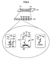
- a reaction solution is poured through scepters 211 and 212.
- the reaction solution contains four kinds of nucleotides each labeled with a different fluorescent dye, and polymerase.
- Each nucleotide is Alexa488-dCTP 214, Cy3-dATP 215, Cy5-dCTP 216 and Cy5.5-dCTP 217.
- Concentration of each nucleotide is 200 nM.
- slat concentration, magnesium concentration and pH are optimized so that the extension reaction is carried out efficiently.
- a gold structure 207 is arranged regularly in a lattice-way in a pitch of 1 ⁇ m.
- One chain of an oligo probe 205 is covalently bonded to one gold structure 207.
- mRNA 206 whose sequence is to be decoded, and the oligo probe 205 are in a hybridized state.
- a caged compound 220 as a photodegradation-active protecting group, is labeled.
- this caged compound 220 inhibits the extension reaction of the complementary strand of the mRNA 206 of a target nucleic acid, the extension reaction does not proceed even if the flow cell is filled with the reaction solution. However, by irradiation of UV light 209 with a wavelength of 260 nm only at the reaction field 201, the caged compound 220 at the terminal of the oligo probe on the reaction field 201 is dissociate, and the extension reaction can be started at arbitrary time.
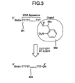
- An oligo probe 301 of the present Embodiment is modified with biotin at the 5' terminal. It aims at immobilizing the oligo probe 301 at the gold structure by utilization of an adipin-biotin bonding. It should be noted that, modification of the 5' terminal is not limited to biotin, and a method for utilizing a covalent bond between an amino group, a maleimide group, or a thiol group and gold can also be used.
- a base sequence of the oligo probe 301 in the present Embodiment takes a polyT sequence.
- the 3' terminal of the oligo probe 301 is modified with the photodegradative protecting group.
- various photodegradative protecting groups have been reported up to now, in the present Embodiment, a 2-nitrobenzyl type, as a typical photodegradative protecting group, was used.
- Optimal wavelength to activate a 2-nitrobenzyl type compound of the present Embodiment is 260 nm. After UV light irradiation, the photodegradative protecting group is deprotected, and the oligo probe 301 is converted to a molecular structure of an oligo probe 303.
- the extension reaction proceeds where the fluorescent labeled nucleotide floating in a solution is incorporated by a polymerase, occurs.
- control of the extension reaction by light irradiation can be carried out.
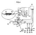
- a device of the present Embodiment is provided with two lasers, an Argon laser 401 with a wavelength of 514 nm, and a He-Ne laser 402 with a wavelength of 633 nm.
- Reason for using two lasers instead of four lasers is to reduce cost, and four lasers may be provided.
- the Argon laser 401 is used to excite an Alexa488-dCTP 214 and a Cy3-dATP 215 of fluorescent labeled nucleotide, while the He-Ne laser 402 is used to excite a Cy5-dCTP 216 and a Cy5.5-dCTP 217.
- Excited light emitted from the Argon laser 401 and the He-Ne laser 402 is reflected at a dichroic mirror 405 and a dichroic mirror 406, respectively, and injected to a bottom surface of a substrate 432 via an ND filter 407, a 4/ ⁇ wavelength plate, a mirror 408, a condenser lens 410 and a prism 411.
- Incident angle is equal to or larger than critical angle, and a fluorescent dye on the flow cell substrate is excited by total reflected illumination.
- advantage of utilizing total reflected illumination is not to excite all fluorescent dyes being free in the reaction solution but to enable to attain local illumination at only an area at the vicinity of about 150 nm in depth in a z direction from the substrate. Therefore, it enables to significantly reduce back light, which becomes noise, as compared with a usual epi-illumination excitation method.
- excited light irradiated on the gold structure generates surface Plasmon resonance and thus can provide several-ten times of enhancement effect of fluorescence in an area with a size nearly to that of the gold structure.
- Fluorescence emitted reaches a dichroic mirror 414 via an objective lens 412, a notch filter 413, and a bandpass filter 440. Fluorescence going straight is still more divided by a dichroic mirror 416, each passing through a bandpass filter 417 and 441 to be focused on image screens of CCD cameras 418 and 420 by condensing lenses 415 and 419. Similarly, fluorescence reflected by the dichroic mirror 414 is still more divided by a dichroic mirror 421, each passing through a bandpass filter 442 and 443 to be focused on image screens of CCD cameras 425 and 423 by condensing lenses 424 and 422. In this way, it becomes possible to acquire simultaneously fluorescence images of four different fluorescent dyes. A signal acquired by each of CCD cameras 418, 420, 423 and 425 is processed by a control PC 426 and converted to a base sequence of mRNA.
- the fluorescent dye is excited using total reflected illumination, however, the fluorescent dye may be excited by installing a nano-opening smaller than wavelength of excited light at the flow cell substrate, and using evanescent light generated by irradiation of the excited light to the opening.
- Control of the extension reaction is carried out by the control PC 426.
- the control PC 426 releases a shutter 445 of a UV laser 444.
- UV light illuminates a bottom surface of a substrate 432 via the same light pass as the above-described evanescent illumination.
- the same optical system is used for irradiation of the UV laser 444 and excitation of the fluorescent dye.
- a illumination method itself of the UV laser is not especially limited to evanescent illumination, and it may also be an often used epi-illumination method or an oblique illumination method.
- the control PC drives a servomotor 433 for driving the XY stage to transfer the next reaction field within a view of an objective lens 412. Still more, the control PC drives an auto focus device 427 under scattering light of the gold structure to focus on a fluorescent molecule at a flow cell wall surface. By repeating this operation, it becomes possible to repeat measurement of the real time base extension reaction sequentially, on 200 reaction fields arranged in the flow cell.
- a temperature adjustment unit 450 is added.
- Fig. 5 shows a flow of the real time reaction.
- a reaction solution containing four kinds of fluorescent deoxynucleotides and a polymerase is poured into a flow cell.
- an XY stage is driven to carry out positioning of a reaction field to be measured.
- auto-focusing is carried out from a scattering image from the gold structure to a flow cell wall surface.
- acquiring of a continuous image of a CCD camera is initiated.
- the photodegradation-active protecting group dissociates to initiate the real time extension reaction.
- illumination of the UV laser is stopped to complete image acquisition.
- a reaction field where the extension reaction is not yet started in the same flow cell, is positioned just under an objective lens. By repeating this operation 200 times for one flow cell, it is possible to realize the real time base extension reaction easily and conveniently without replacing the reaction solution.
- number of the reaction fields in the flow cell is not necessarily limited to 200 described in the present Embodiment.
- number of the flow cells formed at the substrate is also not especially limited.
- a desired reaction field is arranged at an area irradiated with excited light, or an area irradiated with UV light, by stage drive, however, only the desired reaction field may be irradiated with the excited light or the UV light, without transferring the stage but by controlling an optical system.
Landscapes
- Chemical & Material Sciences (AREA)
- Life Sciences & Earth Sciences (AREA)
- Engineering & Computer Science (AREA)
- Health & Medical Sciences (AREA)
- Proteomics, Peptides & Aminoacids (AREA)
- Physics & Mathematics (AREA)
- Organic Chemistry (AREA)
- Analytical Chemistry (AREA)
- Nanotechnology (AREA)
- Biochemistry (AREA)
- General Physics & Mathematics (AREA)
- Immunology (AREA)
- General Health & Medical Sciences (AREA)
- Wood Science & Technology (AREA)
- Zoology (AREA)
- Bioinformatics & Cheminformatics (AREA)
- Condensed Matter Physics & Semiconductors (AREA)
- General Engineering & Computer Science (AREA)
- Microbiology (AREA)
- Genetics & Genomics (AREA)
- Nuclear Medicine, Radiotherapy & Molecular Imaging (AREA)
- Biotechnology (AREA)
- Pathology (AREA)
- Composite Materials (AREA)
- Molecular Biology (AREA)
- Materials Engineering (AREA)
- Crystallography & Structural Chemistry (AREA)
- Biophysics (AREA)
- Measuring Or Testing Involving Enzymes Or Micro-Organisms (AREA)
- Investigating, Analyzing Materials By Fluorescence Or Luminescence (AREA)
- Apparatus Associated With Microorganisms And Enzymes (AREA)
- Investigating Or Analysing Materials By The Use Of Chemical Reactions (AREA)
Applications Claiming Priority (2)
| Application Number | Priority Date | Filing Date | Title |
|---|---|---|---|
| JP2008162667A JP5268444B2 (ja) | 2008-06-23 | 2008-06-23 | 単分子リアルタイムシーケンス装置,核酸分析装置及び単分子リアルタイムシーケンス方法 |
| PCT/JP2009/060808 WO2009157327A1 (fr) | 2008-06-23 | 2009-06-08 | Séquenceur en temps réel de molécules simples, analyseur d'acides nucléiques et procédé de séquençage en temps réel de molécules simples |
Publications (3)
| Publication Number | Publication Date |
|---|---|
| EP2292727A1 true EP2292727A1 (fr) | 2011-03-09 |
| EP2292727A4 EP2292727A4 (fr) | 2011-11-02 |
| EP2292727B1 EP2292727B1 (fr) | 2013-10-23 |
Family
ID=41444395
Family Applications (1)
| Application Number | Title | Priority Date | Filing Date |
|---|---|---|---|
| EP09770037.1A Not-in-force EP2292727B1 (fr) | 2008-06-23 | 2009-06-08 | Séquenceur en temps réel de molécules simples, analyseur d'acides nucléiques et procédé de séquençage en temps réel de molécules simples |
Country Status (5)
| Country | Link |
|---|---|
| US (1) | US20110105358A1 (fr) |
| EP (1) | EP2292727B1 (fr) |
| JP (1) | JP5268444B2 (fr) |
| CN (1) | CN102066548B (fr) |
| WO (1) | WO2009157327A1 (fr) |
Families Citing this family (15)
| Publication number | Priority date | Publication date | Assignee | Title |
|---|---|---|---|---|
| US20120064527A1 (en) * | 2009-05-27 | 2012-03-15 | Akira Maekawa | Nucleic acid analysis device, nucleic acid analysis apparatus, and nucleic acid analysis method |
| JP5663328B2 (ja) * | 2011-01-27 | 2015-02-04 | 株式会社日立ハイテクノロジーズ | 核酸分析装置 |
| JP5659029B2 (ja) * | 2011-01-27 | 2015-01-28 | 株式会社日立ハイテクノロジーズ | ステージ機構およびステージ機構を用いたdnaシーケンサ |
| JP5705579B2 (ja) * | 2011-02-18 | 2015-04-22 | 株式会社日立ハイテクノロジーズ | 分析装置 |
| PL3892295T3 (pl) * | 2011-05-24 | 2023-07-24 | BioNTech SE | Zindywidualizowane szczepionki przeciwnowotworowe |
| WO2014148419A1 (fr) * | 2013-03-19 | 2014-09-25 | 独立行政法人理化学研究所 | Cellule à circulation pour déterminer une séquence d'acide nucléique |
| WO2015074001A1 (fr) * | 2013-11-17 | 2015-05-21 | Quantum-Si Incorporated | Système optique et puce d'analyse pour sonder, détecter et analyser des molécules |
| JP7082860B2 (ja) * | 2013-12-23 | 2022-06-09 | イラミーナ インコーポレーテッド | 光放射の検出を改善するための構造化基板および同構造化基板に関する方法 |
| AU2015222268B2 (en) * | 2014-02-26 | 2017-06-29 | Ventana Medical Systems, Inc. | Photo-selective method for biological sample analysis field |
| RU2016151351A (ru) * | 2015-01-28 | 2019-02-28 | КАБУСИКИ КАЙСЯ ДиЭнЭйФОРМ | Устройство для анализа, чип для анализа, набор для анализа и способ анализа с их применением |
| WO2016151719A1 (fr) * | 2015-03-23 | 2016-09-29 | 株式会社日立製作所 | Dispositif de réaction d'acide nucléique |
| CN105389481B (zh) * | 2015-12-22 | 2018-06-29 | 武汉菲沙基因信息有限公司 | 一种三代全长转录组中可变剪切体的检测方法 |
| BR112020000826A2 (pt) | 2017-07-24 | 2020-07-21 | Quantum-Si Incorporated | instrumento bio-optoeletrônico maciçamente paralelo portátil |
| US20230051226A1 (en) * | 2021-08-10 | 2023-02-16 | Mgi Tech Co., Ltd. | Flow cell imaging systems and methods, and flow cells and other substrates for use in the same |
| US20230364618A1 (en) * | 2022-04-29 | 2023-11-16 | 454 Corporation | Imaging device with light source and image sensor |
Family Cites Families (14)
| Publication number | Priority date | Publication date | Assignee | Title |
|---|---|---|---|---|
| US6136543A (en) * | 1997-01-31 | 2000-10-24 | Hitachi, Ltd. | Method for determining nucleic acids base sequence and apparatus therefor |
| US6917726B2 (en) * | 2001-09-27 | 2005-07-12 | Cornell Research Foundation, Inc. | Zero-mode clad waveguides for performing spectroscopy with confined effective observation volumes |
| ATE377093T1 (de) * | 2000-07-07 | 2007-11-15 | Visigen Biotechnologies Inc | Sequenzbestimmung in echtzeit |
| JP2006503586A (ja) | 2002-10-28 | 2006-02-02 | ゼオトロン コーポレイション | アレイオリゴマー合成および使用 |
| JP2004219369A (ja) * | 2003-01-17 | 2004-08-05 | Toyobo Co Ltd | 表面プラズモン共鳴測定用pdmsマイクロ流路 |
| WO2005080605A2 (fr) * | 2004-02-19 | 2005-09-01 | Helicos Biosciences Corporation | Procedes et kits pour analyser des sequences de polynucleotides |
| JP2006003217A (ja) * | 2004-06-17 | 2006-01-05 | Kyoto Univ | センサチップ及びそれを用いたセンサ装置 |
| US7170050B2 (en) * | 2004-09-17 | 2007-01-30 | Pacific Biosciences Of California, Inc. | Apparatus and methods for optical analysis of molecules |
| US7476504B2 (en) * | 2005-01-31 | 2009-01-13 | Pacific Biosciences Of California, Inc. | Use of reversible extension terminator in nucleic acid sequencing |
| JP2006308332A (ja) * | 2005-04-26 | 2006-11-09 | Moritex Corp | 固定反応物質と液体反応物質との反応用フローセル及び反応装置並びに反応装置の運転方法 |
| JP4890926B2 (ja) * | 2006-04-28 | 2012-03-07 | キヤノン株式会社 | 検出方法、およびキット |
| WO2007147110A2 (fr) * | 2006-06-16 | 2007-12-21 | Pacific Biosciences Of California, Inc. | Initiation régulée d'extension d'amorce |
| US20080241951A1 (en) * | 2006-07-20 | 2008-10-02 | Visigen Biotechnologies, Inc. | Method and apparatus for moving stage detection of single molecular events |
| JP5001019B2 (ja) * | 2007-02-02 | 2012-08-15 | 株式会社日立ハイテクノロジーズ | 生体分子検出素子、生体分子検出素子の製造方法及び生体分子検出方法 |
-
2008
- 2008-06-23 JP JP2008162667A patent/JP5268444B2/ja not_active Expired - Fee Related
-
2009
- 2009-06-08 US US13/001,294 patent/US20110105358A1/en not_active Abandoned
- 2009-06-08 EP EP09770037.1A patent/EP2292727B1/fr not_active Not-in-force
- 2009-06-08 CN CN200980123483.1A patent/CN102066548B/zh not_active Expired - Fee Related
- 2009-06-08 WO PCT/JP2009/060808 patent/WO2009157327A1/fr not_active Ceased
Also Published As
| Publication number | Publication date |
|---|---|
| CN102066548B (zh) | 2015-04-01 |
| US20110105358A1 (en) | 2011-05-05 |
| CN102066548A (zh) | 2011-05-18 |
| EP2292727B1 (fr) | 2013-10-23 |
| EP2292727A4 (fr) | 2011-11-02 |
| JP2010000048A (ja) | 2010-01-07 |
| JP5268444B2 (ja) | 2013-08-21 |
| WO2009157327A1 (fr) | 2009-12-30 |
Similar Documents
| Publication | Publication Date | Title |
|---|---|---|
| EP2292727B1 (fr) | Séquenceur en temps réel de molécules simples, analyseur d'acides nucléiques et procédé de séquençage en temps réel de molécules simples | |
| JP4958770B2 (ja) | 分子相互作用を検出する装置および方法 | |
| EP3336199B1 (fr) | Procédé de séquençage à molécule unique, dispositif, système, et application | |
| AU2024200383A1 (en) | Flow cell device and use thereof | |
| JP4597175B2 (ja) | 標的物質を検出するための分析装置、又は分析方法、若しくはこれら分析装置及び分析方法に用いるデバイス | |
| US20140038274A1 (en) | Nucleic acid analysis device, nucleic acid analysis apparatus, and nucleic acid analysis method | |
| EP2423672A1 (fr) | Dispositif d'analyse d'acide nucléique | |
| WO2006053770A1 (fr) | Pcr en temps reel de cibles sur un microreseau | |
| JP2011501965A (ja) | 核酸のハイ・スループット塩基配列決定のための装置 | |
| EP2180942A2 (fr) | Procédé et appareil pour détecter des événements moléculaires individuels moyennant déplacement | |
| JP2014021081A (ja) | 分析用マイクロ流路チップの製造方法 | |
| WO2010089829A1 (fr) | Appareil de microscope à réflexion interne totale et procédé d'analyse d'un échantillon fluorescent | |
| US7455967B2 (en) | Device for analyzing chemical or biological samples | |
| JP5309092B2 (ja) | 核酸分析用デバイス,核酸分析装置、及び核酸分析用デバイスの製造方法 | |
| US20250012786A1 (en) | Systems and methods for tissue bounds detection | |
| JP5618556B2 (ja) | 核酸分析装置,核酸分析反応デバイス、および核酸分析用反応デバイス用基板 | |
| JP2009244000A (ja) | 蛍光分析方法および装置 | |
| CN1678738A (zh) | 核酸回收芯片和核酸回收装置 | |
| JP6082605B2 (ja) | 分析装置 | |
| JP5145752B2 (ja) | 分析チップ | |
| US20250188524A1 (en) | Graphical user interface and method of estimating an instrument run completion time | |
| WO2024163782A1 (fr) | Conception de cuve à circulation robuste pour transcriptomique spatiale et hybridation in situ qui fonctionne sous haute pression avec des débits accrus et une dynamique de flux améliorée | |
| JP2024179586A (ja) | 流体デバイス、送液システム、及び金属ナノ粒子を含む流体の処理方法 | |
| JPWO1998033939A1 (ja) | 核酸塩基配列決定法及び核酸塩基配列決定装置 |
Legal Events
| Date | Code | Title | Description |
|---|---|---|---|
| PUAI | Public reference made under article 153(3) epc to a published international application that has entered the european phase |
Free format text: ORIGINAL CODE: 0009012 |
|
| 17P | Request for examination filed |
Effective date: 20110114 |
|
| AK | Designated contracting states |
Kind code of ref document: A1 Designated state(s): AT BE BG CH CY CZ DE DK EE ES FI FR GB GR HR HU IE IS IT LI LT LU LV MC MK MT NL NO PL PT RO SE SI SK TR |
|
| AX | Request for extension of the european patent |
Extension state: AL BA RS |
|
| DAX | Request for extension of the european patent (deleted) | ||
| RIC1 | Information provided on ipc code assigned before grant |
Ipc: G01N 21/78 20060101ALI20110922BHEP Ipc: C12Q 1/68 20060101ALI20110922BHEP Ipc: G01N 37/00 20060101ALI20110922BHEP Ipc: C12M 1/00 20060101AFI20110922BHEP |
|
| A4 | Supplementary search report drawn up and despatched |
Effective date: 20110930 |
|
| 17Q | First examination report despatched |
Effective date: 20120531 |
|
| GRAP | Despatch of communication of intention to grant a patent |
Free format text: ORIGINAL CODE: EPIDOSNIGR1 |
|
| RAP1 | Party data changed (applicant data changed or rights of an application transferred) |
Owner name: HITACHI HIGH-TECHNOLOGIES CORPORATION |
|
| RIN1 | Information on inventor provided before grant (corrected) |
Inventor name: KUMAZAKI, NOBUTAKA C/O HITACHI HIGH-TECHNOLOGIES C Inventor name: HAGA, TAKANOBU C/O HITACHI, LTD. Inventor name: TAKAHASHI, SATOSHI C/O HITACHI HIGH-TECHNOLOGIES C Inventor name: KATO, HIROKAZU C/O HITACHI HIGH-TECHNOLOGIES CORPO |
|
| INTG | Intention to grant announced |
Effective date: 20130508 |
|
| GRAP | Despatch of communication of intention to grant a patent |
Free format text: ORIGINAL CODE: EPIDOSNIGR1 |
|
| GRAS | Grant fee paid |
Free format text: ORIGINAL CODE: EPIDOSNIGR3 |
|
| INTG | Intention to grant announced |
Effective date: 20130823 |
|
| RIN1 | Information on inventor provided before grant (corrected) |
Inventor name: KATO, HIROKAZU Inventor name: KUMAZAKI, NOBUTAKA Inventor name: HAGA, TAKANOBU Inventor name: TAKAHASHI, SATOSHI |
|
| GRAA | (expected) grant |
Free format text: ORIGINAL CODE: 0009210 |
|
| AK | Designated contracting states |
Kind code of ref document: B1 Designated state(s): AT BE BG CH CY CZ DE DK EE ES FI FR GB GR HR HU IE IS IT LI LT LU LV MC MK MT NL NO PL PT RO SE SI SK TR |
|
| REG | Reference to a national code |
Ref country code: GB Ref legal event code: FG4D |
|
| REG | Reference to a national code |
Ref country code: CH Ref legal event code: EP |
|
| REG | Reference to a national code |
Ref country code: AT Ref legal event code: REF Ref document number: 637627 Country of ref document: AT Kind code of ref document: T Effective date: 20131115 |
|
| REG | Reference to a national code |
Ref country code: IE Ref legal event code: FG4D |
|
| REG | Reference to a national code |
Ref country code: DE Ref legal event code: R096 Ref document number: 602009019650 Country of ref document: DE Effective date: 20131219 |
|
| REG | Reference to a national code |
Ref country code: NL Ref legal event code: VDEP Effective date: 20131023 |
|
| REG | Reference to a national code |
Ref country code: AT Ref legal event code: MK05 Ref document number: 637627 Country of ref document: AT Kind code of ref document: T Effective date: 20131023 |
|
| REG | Reference to a national code |
Ref country code: LT Ref legal event code: MG4D |
|
| PG25 | Lapsed in a contracting state [announced via postgrant information from national office to epo] |
Ref country code: HR Free format text: LAPSE BECAUSE OF FAILURE TO SUBMIT A TRANSLATION OF THE DESCRIPTION OR TO PAY THE FEE WITHIN THE PRESCRIBED TIME-LIMIT Effective date: 20131023 Ref country code: NO Free format text: LAPSE BECAUSE OF FAILURE TO SUBMIT A TRANSLATION OF THE DESCRIPTION OR TO PAY THE FEE WITHIN THE PRESCRIBED TIME-LIMIT Effective date: 20140123 Ref country code: LT Free format text: LAPSE BECAUSE OF FAILURE TO SUBMIT A TRANSLATION OF THE DESCRIPTION OR TO PAY THE FEE WITHIN THE PRESCRIBED TIME-LIMIT Effective date: 20131023 Ref country code: BE Free format text: LAPSE BECAUSE OF FAILURE TO SUBMIT A TRANSLATION OF THE DESCRIPTION OR TO PAY THE FEE WITHIN THE PRESCRIBED TIME-LIMIT Effective date: 20131023 Ref country code: NL Free format text: LAPSE BECAUSE OF FAILURE TO SUBMIT A TRANSLATION OF THE DESCRIPTION OR TO PAY THE FEE WITHIN THE PRESCRIBED TIME-LIMIT Effective date: 20131023 Ref country code: SE Free format text: LAPSE BECAUSE OF FAILURE TO SUBMIT A TRANSLATION OF THE DESCRIPTION OR TO PAY THE FEE WITHIN THE PRESCRIBED TIME-LIMIT Effective date: 20131023 Ref country code: FI Free format text: LAPSE BECAUSE OF FAILURE TO SUBMIT A TRANSLATION OF THE DESCRIPTION OR TO PAY THE FEE WITHIN THE PRESCRIBED TIME-LIMIT Effective date: 20131023 Ref country code: IS Free format text: LAPSE BECAUSE OF FAILURE TO SUBMIT A TRANSLATION OF THE DESCRIPTION OR TO PAY THE FEE WITHIN THE PRESCRIBED TIME-LIMIT Effective date: 20140223 |
|
| PG25 | Lapsed in a contracting state [announced via postgrant information from national office to epo] |
Ref country code: LV Free format text: LAPSE BECAUSE OF FAILURE TO SUBMIT A TRANSLATION OF THE DESCRIPTION OR TO PAY THE FEE WITHIN THE PRESCRIBED TIME-LIMIT Effective date: 20131023 Ref country code: CY Free format text: LAPSE BECAUSE OF FAILURE TO SUBMIT A TRANSLATION OF THE DESCRIPTION OR TO PAY THE FEE WITHIN THE PRESCRIBED TIME-LIMIT Effective date: 20131023 Ref country code: ES Free format text: LAPSE BECAUSE OF FAILURE TO SUBMIT A TRANSLATION OF THE DESCRIPTION OR TO PAY THE FEE WITHIN THE PRESCRIBED TIME-LIMIT Effective date: 20131023 Ref country code: AT Free format text: LAPSE BECAUSE OF FAILURE TO SUBMIT A TRANSLATION OF THE DESCRIPTION OR TO PAY THE FEE WITHIN THE PRESCRIBED TIME-LIMIT Effective date: 20131023 |
|
| PG25 | Lapsed in a contracting state [announced via postgrant information from national office to epo] |
Ref country code: PT Free format text: LAPSE BECAUSE OF FAILURE TO SUBMIT A TRANSLATION OF THE DESCRIPTION OR TO PAY THE FEE WITHIN THE PRESCRIBED TIME-LIMIT Effective date: 20140224 |
|
| REG | Reference to a national code |
Ref country code: DE Ref legal event code: R097 Ref document number: 602009019650 Country of ref document: DE |
|
| PG25 | Lapsed in a contracting state [announced via postgrant information from national office to epo] |
Ref country code: EE Free format text: LAPSE BECAUSE OF FAILURE TO SUBMIT A TRANSLATION OF THE DESCRIPTION OR TO PAY THE FEE WITHIN THE PRESCRIBED TIME-LIMIT Effective date: 20131023 |
|
| PG25 | Lapsed in a contracting state [announced via postgrant information from national office to epo] |
Ref country code: PL Free format text: LAPSE BECAUSE OF FAILURE TO SUBMIT A TRANSLATION OF THE DESCRIPTION OR TO PAY THE FEE WITHIN THE PRESCRIBED TIME-LIMIT Effective date: 20131023 Ref country code: SK Free format text: LAPSE BECAUSE OF FAILURE TO SUBMIT A TRANSLATION OF THE DESCRIPTION OR TO PAY THE FEE WITHIN THE PRESCRIBED TIME-LIMIT Effective date: 20131023 Ref country code: IT Free format text: LAPSE BECAUSE OF FAILURE TO SUBMIT A TRANSLATION OF THE DESCRIPTION OR TO PAY THE FEE WITHIN THE PRESCRIBED TIME-LIMIT Effective date: 20131023 Ref country code: RO Free format text: LAPSE BECAUSE OF FAILURE TO SUBMIT A TRANSLATION OF THE DESCRIPTION OR TO PAY THE FEE WITHIN THE PRESCRIBED TIME-LIMIT Effective date: 20131023 Ref country code: CZ Free format text: LAPSE BECAUSE OF FAILURE TO SUBMIT A TRANSLATION OF THE DESCRIPTION OR TO PAY THE FEE WITHIN THE PRESCRIBED TIME-LIMIT Effective date: 20131023 |
|
| PLBE | No opposition filed within time limit |
Free format text: ORIGINAL CODE: 0009261 |
|
| STAA | Information on the status of an ep patent application or granted ep patent |
Free format text: STATUS: NO OPPOSITION FILED WITHIN TIME LIMIT |
|
| PG25 | Lapsed in a contracting state [announced via postgrant information from national office to epo] |
Ref country code: DK Free format text: LAPSE BECAUSE OF FAILURE TO SUBMIT A TRANSLATION OF THE DESCRIPTION OR TO PAY THE FEE WITHIN THE PRESCRIBED TIME-LIMIT Effective date: 20131023 |
|
| 26N | No opposition filed |
Effective date: 20140724 |
|
| REG | Reference to a national code |
Ref country code: DE Ref legal event code: R097 Ref document number: 602009019650 Country of ref document: DE Effective date: 20140724 |
|
| PG25 | Lapsed in a contracting state [announced via postgrant information from national office to epo] |
Ref country code: MC Free format text: LAPSE BECAUSE OF FAILURE TO SUBMIT A TRANSLATION OF THE DESCRIPTION OR TO PAY THE FEE WITHIN THE PRESCRIBED TIME-LIMIT Effective date: 20131023 Ref country code: LU Free format text: LAPSE BECAUSE OF FAILURE TO SUBMIT A TRANSLATION OF THE DESCRIPTION OR TO PAY THE FEE WITHIN THE PRESCRIBED TIME-LIMIT Effective date: 20140608 |
|
| REG | Reference to a national code |
Ref country code: CH Ref legal event code: PL |
|
| PG25 | Lapsed in a contracting state [announced via postgrant information from national office to epo] |
Ref country code: SI Free format text: LAPSE BECAUSE OF FAILURE TO SUBMIT A TRANSLATION OF THE DESCRIPTION OR TO PAY THE FEE WITHIN THE PRESCRIBED TIME-LIMIT Effective date: 20131023 |
|
| REG | Reference to a national code |
Ref country code: IE Ref legal event code: MM4A |
|
| PG25 | Lapsed in a contracting state [announced via postgrant information from national office to epo] |
Ref country code: IE Free format text: LAPSE BECAUSE OF NON-PAYMENT OF DUE FEES Effective date: 20140608 Ref country code: CH Free format text: LAPSE BECAUSE OF NON-PAYMENT OF DUE FEES Effective date: 20140630 Ref country code: LI Free format text: LAPSE BECAUSE OF NON-PAYMENT OF DUE FEES Effective date: 20140630 |
|
| PG25 | Lapsed in a contracting state [announced via postgrant information from national office to epo] |
Ref country code: MT Free format text: LAPSE BECAUSE OF FAILURE TO SUBMIT A TRANSLATION OF THE DESCRIPTION OR TO PAY THE FEE WITHIN THE PRESCRIBED TIME-LIMIT Effective date: 20131023 |
|
| REG | Reference to a national code |
Ref country code: FR Ref legal event code: PLFP Year of fee payment: 8 |
|
| PG25 | Lapsed in a contracting state [announced via postgrant information from national office to epo] |
Ref country code: BG Free format text: LAPSE BECAUSE OF FAILURE TO SUBMIT A TRANSLATION OF THE DESCRIPTION OR TO PAY THE FEE WITHIN THE PRESCRIBED TIME-LIMIT Effective date: 20131023 Ref country code: GR Free format text: LAPSE BECAUSE OF FAILURE TO SUBMIT A TRANSLATION OF THE DESCRIPTION OR TO PAY THE FEE WITHIN THE PRESCRIBED TIME-LIMIT Effective date: 20140124 |
|
| PG25 | Lapsed in a contracting state [announced via postgrant information from national office to epo] |
Ref country code: HU Free format text: LAPSE BECAUSE OF FAILURE TO SUBMIT A TRANSLATION OF THE DESCRIPTION OR TO PAY THE FEE WITHIN THE PRESCRIBED TIME-LIMIT; INVALID AB INITIO Effective date: 20090608 Ref country code: TR Free format text: LAPSE BECAUSE OF FAILURE TO SUBMIT A TRANSLATION OF THE DESCRIPTION OR TO PAY THE FEE WITHIN THE PRESCRIBED TIME-LIMIT Effective date: 20131023 |
|
| REG | Reference to a national code |
Ref country code: FR Ref legal event code: PLFP Year of fee payment: 9 |
|
| REG | Reference to a national code |
Ref country code: FR Ref legal event code: PLFP Year of fee payment: 10 |
|
| PG25 | Lapsed in a contracting state [announced via postgrant information from national office to epo] |
Ref country code: MK Free format text: LAPSE BECAUSE OF FAILURE TO SUBMIT A TRANSLATION OF THE DESCRIPTION OR TO PAY THE FEE WITHIN THE PRESCRIBED TIME-LIMIT Effective date: 20131023 |
|
| REG | Reference to a national code |
Ref country code: DE Ref legal event code: R082 Ref document number: 602009019650 Country of ref document: DE Representative=s name: STREHL SCHUEBEL-HOPF & PARTNER MBB PATENTANWAE, DE Ref country code: DE Ref legal event code: R081 Ref document number: 602009019650 Country of ref document: DE Owner name: HITACHI HIGH-TECH CORPORATION, JP Free format text: FORMER OWNER: HITACHI HIGH-TECHNOLOGIES CORPORATION, TOKYO, JP |
|
| PGFP | Annual fee paid to national office [announced via postgrant information from national office to epo] |
Ref country code: FR Payment date: 20200512 Year of fee payment: 12 Ref country code: DE Payment date: 20200527 Year of fee payment: 12 |
|
| PGFP | Annual fee paid to national office [announced via postgrant information from national office to epo] |
Ref country code: GB Payment date: 20200527 Year of fee payment: 12 |
|
| REG | Reference to a national code |
Ref country code: DE Ref legal event code: R119 Ref document number: 602009019650 Country of ref document: DE |
|
| GBPC | Gb: european patent ceased through non-payment of renewal fee |
Effective date: 20210608 |
|
| PG25 | Lapsed in a contracting state [announced via postgrant information from national office to epo] |
Ref country code: GB Free format text: LAPSE BECAUSE OF NON-PAYMENT OF DUE FEES Effective date: 20210608 Ref country code: DE Free format text: LAPSE BECAUSE OF NON-PAYMENT OF DUE FEES Effective date: 20220101 |
|
| PG25 | Lapsed in a contracting state [announced via postgrant information from national office to epo] |
Ref country code: FR Free format text: LAPSE BECAUSE OF NON-PAYMENT OF DUE FEES Effective date: 20210630 |