EP2292832A2 - Machinery for dedusting, washing and drying carpets - Google Patents
Machinery for dedusting, washing and drying carpets Download PDFInfo
- Publication number
- EP2292832A2 EP2292832A2 EP10007354A EP10007354A EP2292832A2 EP 2292832 A2 EP2292832 A2 EP 2292832A2 EP 10007354 A EP10007354 A EP 10007354A EP 10007354 A EP10007354 A EP 10007354A EP 2292832 A2 EP2292832 A2 EP 2292832A2
- Authority
- EP
- European Patent Office
- Prior art keywords
- carpet
- washing
- carpets
- centrifuging
- station
- Prior art date
- Legal status (The legal status is an assumption and is not a legal conclusion. Google has not performed a legal analysis and makes no representation as to the accuracy of the status listed.)
- Granted
Links
Images



Classifications
-
- A—HUMAN NECESSITIES
- A47—FURNITURE; DOMESTIC ARTICLES OR APPLIANCES; COFFEE MILLS; SPICE MILLS; SUCTION CLEANERS IN GENERAL
- A47L—DOMESTIC WASHING OR CLEANING; SUCTION CLEANERS IN GENERAL
- A47L11/00—Machines for cleaning floors, carpets, furniture, walls, or wall coverings
- A47L11/34—Machines for treating carpets in position by liquid, foam, or vapour, e.g. by steam
-
- D—TEXTILES; PAPER
- D06—TREATMENT OF TEXTILES OR THE LIKE; LAUNDERING; FLEXIBLE MATERIALS NOT OTHERWISE PROVIDED FOR
- D06G—MECHANICAL OR PRESSURE CLEANING OF CARPETS, RUGS, SACKS, HIDES, OR OTHER SKIN OR TEXTILE ARTICLES OR FABRICS; TURNING INSIDE-OUT FLEXIBLE TUBULAR OR OTHER HOLLOW ARTICLES
- D06G1/00—Beating, brushing, or otherwise mechanically cleaning or pressure cleaning carpets, rugs, sacks, hides, or other skin or textile articles or fabrics
Definitions
- the invention refers to a machine for washing carpets, which includes operations for removing the dust dry, cleaning the carpet with the corresponding liquids and detergents, and centrifuging it after washing, all in the same machine, without the need for auxiliary machines for the first and third operations.
- the brush-holding carriage is held and guided on flat plates placed transversally with regard to the conveyor belt, completed with cross members parallel to the plate for the side guiding rollers of the carriage, moving transversally with regard to the carpet, of forward and backward movement.
- this type of machine needs, for the washing process to be complete, in addition to a machine for shaking the carpet, in some instances this is carried out manually, and another machine for centrifuging the carpet, namely a centrifuge, making the users of these machines need large premises and abundant labour to move the carpets from one machine to the next.
- the machine object of the invention comprises a frame, formed by side bedplates joined by longitudinal cross members, a carpet shaking station with the aim of releasing the small particles of dirt in it, a washing station for the carpet with the corresponding brushes cleaners and means to supply liquids such as water and detergents, and subsequent collection, and a centrifuge station for the carpet when clean.
- a complementary element which is a carriage for moving the washed carpet, from the rear of the machine, to one of its side parts where there is the loading mouth of the centrifuge station.
- This carriage has a slope formed by rollers, designed so that one height of the slope is composed of the rollers for winding the carpet once it has been washed in the washing station, and a second height at the opening of the loading mouth of the centrifuge station.
- the shaking, washing, and centrifuge stations work continuously, so that once the carpet is washed, it is collected in the same machine and is placed manually with the help of the aforementioned carriage, in the centrifuge located in the lower side of the machine.
- the positioning of the three aforementioned stations, namely shaking, washing and centrifuge for drying is as follows:
- the shaking station of the carpet is positioned at the lower front side of the frame, and comprises means for turning that hit the surface of the carpet shaking it from below, and releasing the particles of dirt and dust on the top side, so they it be vacuumed and then collected in a tray located horizontally under these means of turning, which comprise a shaft placed horizontally at the lower side of the machine, whose ends rest on the side bedplates through the corresponding supports with bearings, and with movement supplied to the shaft by means of the corresponding geared motor.
- the washing station occupies the upper position and works with means of movement such as rails placed horizontally on the machine bedplate, and fitted with the corresponding end of travel stops, positioned variably, on which slide, in a programmed manner, and affected by a forward backward movement left right and vice versa, a cleaning carriage that acts on the top side of the carpet, exerting its action through a set of small-diameter brushes, these brushes turn in opposite directions or the same direction, depending on type of carpet, with possibility of adjusting the pressure of the brushes on the surface of the carpet to be cleaned, as well as varying the cleaning carriage speed, at the same time moving the carpet forward as well as the transversal movement, while at the same time brushing and adding water and detergents, through the corresponding nozzles located beside the brushes.
- the dirty water and detergent used in the washing station is collected in a tray located at the bottom of the washing station and which extends the whole width of the machine, this tray empties into the corresponding drain and is connected to the general sewer with a pump for moving it from the machine to the sewer.
- the carriage cleaner is moved by a transversal toothed-belt driven by a geared motor that moves the cleaning carriage in a forwards-backwards motion over the entire width of the machine, with a flexible chain containing tubes for water and the detergent.
- the centrifuge station occupies a central and lower position on the machine, and the centrifuge chamber has its entry portal in a bracket parallel to the right-hand bedplate of the same, with the corresponding hatch, on the inside of the chamber there is the centrifuge drum, driven by an electric motor located on the left-hand bedplate of the machine.
- the hatch of centrifuge chamber has means of support for turning the centrifuge drum, such as a vertical plate bracket joined to the side bedplates by suitable means, and some means to absorb the drum vibrations that include coil springs and one or more shock absorbers, which are connected to the support bracket by one of their ends and the opposite end connects to a metal section resting on the floor.
- means of support for turning the centrifuge drum such as a vertical plate bracket joined to the side bedplates by suitable means, and some means to absorb the drum vibrations that include coil springs and one or more shock absorbers, which are connected to the support bracket by one of their ends and the opposite end connects to a metal section resting on the floor.
- the water expelled in spinning operations is evacuated through a suitable conduit, moved by an electric sucking-blowing pump located at the lower rear of the machine (10).
- the machine object of the invention could be manufactured, at the client's request, without the shaker, or centrifuge station, without having to change the design, making the manufacturing price more economic.
- the Machine (10) presents on a frame formed by side bedplates (11-12) and some cross members (35), some of them hidden in Figures 1 and 2 , forming a tough structure, on which the different parts and pieces that form part of it are fitted, formed on the station level by:
- the shaking station is formed by a longitudinal prism-shaped body (44), whose end parts are resting through the supports and bearings (45) on the side bedplates (11-12), with the help of semi-shafts that are born in its smaller side bases and that rest and turn on these supports (45).
- the prism (44) presents in the upper and lower bases, a steel bar or similar material (43) welded to the same, as can be seen in Figures 4 and 5 .
- the longitudinal prism (44) is fitted behind the traction cylinders (19-26), see Fig. 1 , and the function of the latter (19-26) is to hold the carpet (18) with them when turning in opposite directions and locating the carpet over the prism (44) which when turning and through a the aid of the bars (43) shakes the carpet (18) to dislodge the dust it contains, and it is deposited in the tray (62), that can be removed from the machine. (10) for cleaning, thanks to the inlet portal (63) the heavier and larger particles, while the lighter that are in the air after shaking are sucked up by the vacuum inlet (61), on the side bedplate (12) with the aid of a vacuum hose not represented in the illustrations, whose sucking mouth is located at the mouth (61).
- the tray (62), as can be seen in Fig. 1 rests on the side bedplates (11-12) and occupies a horizontal position under the plane of the movement cylinders (19-26), and can be removed from the machine. (10) from the side by the inlet portal (64) in the bedplate side (11), as can be seen in detail "1" of Fig. 1 , to remove the dust deposited on it, and replace it.
- the washing station comprises a cleaning carriage (13) that moves on longitudinal rails (14-15) whose ends are welded or similar method to the bedplates (11-12), as can be seen in Fig. 1 , helped by the wheels (62), moving the carriage (13) progressively along the rails (14-15), cleaning the carpet (18), with the cleaning rollers (19) pouring into the (18) water the appropriate detergents, which later fall onto the tray (41) located below the rollers (72-73), with a sloping bottom to facilitate the evacuation of the soapy water by the most adequate means, as can be seen in Figures 1 and 2 , this evacuation being carried out with an electric sucking and blowing pump (59), built in the lower rear side of the machine (10).
- the drying station comprises a centrifuge drum (46) placed horizontally in the lower side of the machine (10), with a loading mouth (47) or inlet portal which is cut back in the side bedplate (11), as can be seen in Fig. 7 , and of the bracket plate (76) which (47) has a door (21) to close the centrifuge station, whose drum (46) turns on semi-axles (23) not illustrated in the figures.
- the centrifuge drum (46) rests on its ends on the side bedplates (11-12), through the corresponding supports (48-49) with the corresponding bearings not illustrated in the figures.
- the centrifuge drum (46) turns thanks to an electric motor (31) built into the side bedplate (12), whose outlet shaft is fitted to the drum (46) by suitable means.
- the means for opening and closing the door (21) are as shown in Figures 3 and 6 , a tab (54) that projects from one of the vertical sides of the door (21) and with an orifice (65), in which the shaft (55) of the piston (56) enters so as to lock the door in a programmed manner (21), once the carpet (18) is inside the centrifuge drum (46), the liquid used in these centrifuge operations, is evacuated by an electric sucking-blowing pump for water (58) fitted to the lower rear side of the machine (10).
- the centrifuge station has means to absorb the vibrations produced by the centrifuge drum (46), comprising a support plate (76) joined to the side bedplate (11) through tabs (77), coil springs (67) that rest on a metal section (68) attached to the floor, to which is joined, by suitable means, a damper (52) that complements the action of the coil springs (67).
- the door (21) incorporates means to hold the centrifuge drum (46), such as the support (48), secured to the door (21) with nuts and bolts (50), as can be seen in Fig. 6 , the rear of the door (21) having a disc (69), as a means to ensure sealing when closing the door (21) in the inlet portal (47).
- a carriage (89) has been designed with the essential feature that the height of the cross members (83) at their highest point, is almost equal to the height of the roller (72) on which the carpet (18) is wound after passing through the washing station, and the height of the lowest point of the cross members (83) is almost equal that of the inlet portal (47) of the centrifuge drum (46).
- the machine (10) works as follows: The operator enters the carpet (18) between the rollers (19-26) located at the front of the machine (10), which (19-26) as they turn in opposite directions, they drag the carpet (18) inside of machine (10), locating it above the shaker prism (44) which with the help of the bars (43) hits the carpet (18) by from the underside, shaking the dust, which is collected, according to the size of the particles, in the tray (62) or vacuumed via the inlet portal (61), then the carpet (18) is expelled, so that the operator can locate the edge of the carpet (18) on the conveyor belt (16) which moves (18) forward, until it is located vertically in the washing station (13) and its rollers (70) which brush the carpet at the same time in a programmed manner (13) and via suitable passageways, pours water and detergents onto the carpet (18), while at the same time the station (13) moves from right to left of the rails (14-15) in a backwards and forwards movement, adapted to the width of the carpet (18), pouring the detergents
- the shaft (55) of the pneumatic or hydraulic piston (56) moves forward on the tab (54) entering the orifice (55) in the bore (66), locking the door (21), and the programmed centrifuge operations are started, the duration of which will depend on the dimensions and weight of the carpet (18) to be washed.
Landscapes
- Engineering & Computer Science (AREA)
- Mechanical Engineering (AREA)
- Textile Engineering (AREA)
- Treatment Of Fiber Materials (AREA)
- Accessory Of Washing/Drying Machine, Commercial Washing/Drying Machine, Other Washing/Drying Machine (AREA)
- Centrifugal Separators (AREA)
Abstract
Description
- The invention refers to a machine for washing carpets, which includes operations for removing the dust dry, cleaning the carpet with the corresponding liquids and detergents, and centrifuging it after washing, all in the same machine, without the need for auxiliary machines for the first and third operations.
- On the market there are, and therefore they can be considered as state of the art, a multitude of machines for washing carpets, but they need other machines for the wash to be complete, for before the washing and after, namely the prior shaking of the dust, and centrifuging after washing.
- A good cleaning needs to first remove the dust accumulated between the fibres before washing with liquids and detergents, to avoid the dust adhering to the fibres when receiving the liquids and detergents, when the dust has been removed, the carpet must be moved to the washing machine, for instance, Spanish Invention Patent of the same applicant, No.
9202117 - The brush-holding carriage is held and guided on flat plates placed transversally with regard to the conveyor belt, completed with cross members parallel to the plate for the side guiding rollers of the carriage, moving transversally with regard to the carpet, of forward and backward movement.
- However, this type of machine needs, for the washing process to be complete, in addition to a machine for shaking the carpet, in some instances this is carried out manually, and another machine for centrifuging the carpet, namely a centrifuge, making the users of these machines need large premises and abundant labour to move the carpets from one machine to the next.
- Integrating the operations for removing the dust, washing the carpet, and centrifuging in a single machine, in the minimum space and practically eliminating all physical labour necessary for moving the carpets from one machine to the next, especially important if we consider that some sizes of carpet when dry have a considerable weight, which increases when it has been washed and therefore needing two people to move it into the centrifuge.
- The machine object of the invention comprises a frame, formed by side bedplates joined by longitudinal cross members, a carpet shaking station with the aim of releasing the small particles of dirt in it, a washing station for the carpet with the corresponding brushes cleaners and means to supply liquids such as water and detergents, and subsequent collection, and a centrifuge station for the carpet when clean.
- To avoid having to carry the carpet manually to the centrifuge station once washed, there is a complementary element, which is a carriage for moving the washed carpet, from the rear of the machine, to one of its side parts where there is the loading mouth of the centrifuge station.
- This carriage has a slope formed by rollers, designed so that one height of the slope is composed of the rollers for winding the carpet once it has been washed in the washing station, and a second height at the opening of the loading mouth of the centrifuge station.
- The shaking, washing, and centrifuge stations, work continuously, so that once the carpet is washed, it is collected in the same machine and is placed manually with the help of the aforementioned carriage, in the centrifuge located in the lower side of the machine.
- The positioning of the three aforementioned stations, namely shaking, washing and centrifuge for drying is as follows: The shaking station of the carpet is positioned at the lower front side of the frame, and comprises means for turning that hit the surface of the carpet shaking it from below, and releasing the particles of dirt and dust on the top side, so they it be vacuumed and then collected in a tray located horizontally under these means of turning, which comprise a shaft placed horizontally at the lower side of the machine, whose ends rest on the side bedplates through the corresponding supports with bearings, and with movement supplied to the shaft by means of the corresponding geared motor.
- The washing station occupies the upper position and works with means of movement such as rails placed horizontally on the machine bedplate, and fitted with the corresponding end of travel stops, positioned variably, on which slide, in a programmed manner, and affected by a forward backward movement left right and vice versa, a cleaning carriage that acts on the top side of the carpet, exerting its action through a set of small-diameter brushes, these brushes turn in opposite directions or the same direction, depending on type of carpet, with possibility of adjusting the pressure of the brushes on the surface of the carpet to be cleaned, as well as varying the cleaning carriage speed, at the same time moving the carpet forward as well as the transversal movement, while at the same time brushing and adding water and detergents, through the corresponding nozzles located beside the brushes.
- The dirty water and detergent used in the washing station is collected in a tray located at the bottom of the washing station and which extends the whole width of the machine, this tray empties into the corresponding drain and is connected to the general sewer with a pump for moving it from the machine to the sewer.
- The carriage cleaner is moved by a transversal toothed-belt driven by a geared motor that moves the cleaning carriage in a forwards-backwards motion over the entire width of the machine, with a flexible chain containing tubes for water and the detergent.
- The centrifuge station occupies a central and lower position on the machine, and the centrifuge chamber has its entry portal in a bracket parallel to the right-hand bedplate of the same, with the corresponding hatch, on the inside of the chamber there is the centrifuge drum, driven by an electric motor located on the left-hand bedplate of the machine.
- The hatch of centrifuge chamber has means of support for turning the centrifuge drum, such as a vertical plate bracket joined to the side bedplates by suitable means, and some means to absorb the drum vibrations that include coil springs and one or more shock absorbers, which are connected to the support bracket by one of their ends and the opposite end connects to a metal section resting on the floor.
- The water expelled in spinning operations is evacuated through a suitable conduit, moved by an electric sucking-blowing pump located at the lower rear of the machine (10).
- Due to its design, the machine object of the invention could be manufactured, at the client's request, without the shaker, or centrifuge station, without having to change the design, making the manufacturing price more economic.
- Other details and characteristics shall be shown throughout the description below referring to drawings attached to this report which are shown for illustrative but not limiting purposes only in a drawing of the invention.
-
-
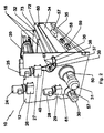
Fig. 1 is a general perspective of the washing machine (10) in which its outer parts can be seen from the front. -
Fig. 2 is a general perspective of the washing machine (10) in which its outer parts can be seen from the back. -
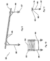
Fig. 3 is a side elevation view of the door (21) supported by the side bedplate (11) of the machine. (10) by means of a bracket plate (22). -
Fig. 4 is another side elevation view of the door (21) and its closing devices. -
Fig. 5 is a side elevation view of the shaker prism (44). -
Fig. 6 is a front elevation view of the shaker prism (44). -
Fig. 7 is a front elevation view of the bracket plate (76) of the centrifuge drum (46), this bracket is resting on the metal section (68), with the aid of coil springs (67), and one or more shock absorbers (67). -
Fig. 8 is a view of the rear of the door (21) incorporating a disc (74) that fits into the entry portal (47) of the centrifuge drum (46). -
Fig. 9 is a side elevation view of the carpet-holding trolley (79). -
Fig. 10 is a front elevation view of the carpet-holding trolley (79). -
Fig. 11 is a detail of the tray support (62). - Below is a list of the machine's main components, depicted in the illustrations with the following numbers: (10) machine, (11-12) side bedplates, (13) washing station, (14-15) rail guide, (16) continuous belt, (17) roller, (18) carpet, (19) rollers, (20) cable holder chain, (21) door, (22) plate bracket, (23) door turning axis, (24- 25) electric motors, (26-27) electric motor reduction gears, (24-25), (28) electric motor, (29) electric motor reduction gear (28), (30-31) electric motors, (32) roller, (33) belts, (34) tray, (35) handrails, (36-37) semi-shafts, (38-39) transport chain, (40) toothed pulley, (41) rear tray, (42) semi-shafts, (43) bars, (44) shaker prism, (45) supports of prism (44), (46) centrifuge drum, (47) entry portal, (48-49) centrifuge drum supports, (49) drum, (50) geared motor, (51) handle, (52) damper, (53) bolts, (54) tab, (55) shaft, (56) pneumatic cylinder, (57) tank open, (58) electric pump, (59) electric pump, (60) tray to collect liquids, (61) inlet for sucking dust, (62) tray, (63) inlet portal tray (62), (64) entry portal, (65) orifice, (66) springs, (67) toothed wheels, (68) metal section, (69) disc, (70) cleaner rollers of washing station (13), (71) roller, (72-73) rollers, (74) sealing disc of door (21), (75) centring devices, (76) centrifuge drum support, (77) plates, (78) drilled holes, (79) support metal section of tray (62), (80) foot, (81) wheel, (83) longitudinal beams, (84) cross members, (85) rollers, (86) props, (87) wheels, (88) cross members, (89) carriage for moving the carpets.
- In one of the preferred embodiments of the invention, as can be seen in
Fig. 1 , the Machine (10) presents on a frame formed by side bedplates (11-12) and some cross members (35), some of them hidden inFigures 1 and2 , forming a tough structure, on which the different parts and pieces that form part of it are fitted, formed on the station level by: - A station for shaking the dust comprising a shaker (44) that rests its ends on the supports (45).
- A washing station, comprising a cleaning carriage (13).
- A drying station, comprising a centrifuge drum (46).
- A carriage (89) for moving the wet carpets.
- The shaking station is formed by a longitudinal prism-shaped body (44), whose end parts are resting through the supports and bearings (45) on the side bedplates (11-12), with the help of semi-shafts that are born in its smaller side bases and that rest and turn on these supports (45). In turn, the prism (44) presents in the upper and lower bases, a steel bar or similar material (43) welded to the same, as can be seen in
Figures 4 and 5 . - The longitudinal prism (44) is fitted behind the traction cylinders (19-26), see
Fig. 1 , and the function of the latter (19-26) is to hold the carpet (18) with them when turning in opposite directions and locating the carpet over the prism (44) which when turning and through a the aid of the bars (43) shakes the carpet (18) to dislodge the dust it contains, and it is deposited in the tray (62), that can be removed from the machine. (10) for cleaning, thanks to the inlet portal (63) the heavier and larger particles, while the lighter that are in the air after shaking are sucked up by the vacuum inlet (61), on the side bedplate (12) with the aid of a vacuum hose not represented in the illustrations, whose sucking mouth is located at the mouth (61). - The tray (62), as can be seen in
Fig. 1 rests on the side bedplates (11-12) and occupies a horizontal position under the plane of the movement cylinders (19-26), and can be removed from the machine. (10) from the side by the inlet portal (64) in the bedplate side (11), as can be seen in detail "1" ofFig. 1 , to remove the dust deposited on it, and replace it. - To help with the removal of the tray (62) from the machine. (10) by one of its side bedplates, and as shown in
Fig. 11 , there is a foot (80), on whose lower ends there is a wheel (81). - The washing station comprises a cleaning carriage (13) that moves on longitudinal rails (14-15) whose ends are welded or similar method to the bedplates (11-12), as can be seen in
Fig. 1 , helped by the wheels (62), moving the carriage (13) progressively along the rails (14-15), cleaning the carpet (18), with the cleaning rollers (19) pouring into the (18) water the appropriate detergents, which later fall onto the tray (41) located below the rollers (72-73), with a sloping bottom to facilitate the evacuation of the soapy water by the most adequate means, as can be seen inFigures 1 and2 , this evacuation being carried out with an electric sucking and blowing pump (59), built in the lower rear side of the machine (10). - The movement of the carpet (18) on the continuous belts (16) is achieved a through the cylinders (17-32), see
Figures 1 and2 , which (17-32) turn thanks to the fact that they incorporate in the ends of the semi-axles (36-37), toothed wheels (67), that receive the traction from the electric motor (25) with its gear reducer (27) and the aid of chains (38-39). - The drying station comprises a centrifuge drum (46) placed horizontally in the lower side of the machine (10), with a loading mouth (47) or inlet portal which is cut back in the side bedplate (11), as can be seen in
Fig. 7 , and of the bracket plate (76) which (47) has a door (21) to close the centrifuge station, whose drum (46) turns on semi-axles (23) not illustrated in the figures. - The centrifuge drum (46) rests on its ends on the side bedplates (11-12), through the corresponding supports (48-49) with the corresponding bearings not illustrated in the figures. The centrifuge drum (46) turns thanks to an electric motor (31) built into the side bedplate (12), whose outlet shaft is fitted to the drum (46) by suitable means.
- To seal the centrifuge station, there is a door (21), with means for opening and closing on the inlet portal or loading mouth (47). The means for opening and closing the door (21) are as shown in
Figures 3 and6 , a tab (54) that projects from one of the vertical sides of the door (21) and with an orifice (65), in which the shaft (55) of the piston (56) enters so as to lock the door in a programmed manner (21), once the carpet (18) is inside the centrifuge drum (46), the liquid used in these centrifuge operations, is evacuated by an electric sucking-blowing pump for water (58) fitted to the lower rear side of the machine (10). - In turn, the centrifuge station has means to absorb the vibrations produced by the centrifuge drum (46), comprising a support plate (76) joined to the side bedplate (11) through tabs (77), coil springs (67) that rest on a metal section (68) attached to the floor, to which is joined, by suitable means, a damper (52) that complements the action of the coil springs (67).
- The door (21) incorporates means to hold the centrifuge drum (46), such as the support (48), secured to the door (21) with nuts and bolts (50), as can be seen in
Fig. 6 , the rear of the door (21) having a disc (69), as a means to ensure sealing when closing the door (21) in the inlet portal (47). - As a complementary and specific element to move the wet carpet (18) after it has been washed in the washing station, and to move it to the centrifuge station, see
figures 9 and 10 , a carriage (89) has been designed with the essential feature that the height of the cross members (83) at their highest point, is almost equal to the height of the roller (72) on which the carpet (18) is wound after passing through the washing station, and the height of the lowest point of the cross members (83) is almost equal that of the inlet portal (47) of the centrifuge drum (46). These beams (83) are parallel and are joined by means of cross members (84), and the carriage rests on the floor through the props (86), joined by cross members (88), and the wheels (87) located at the ends of said sections (80), between the longitudinal beams (83) the free-turning rollers (85) are fitted. - The machine (10) works as follows: The operator enters the carpet (18) between the rollers (19-26) located at the front of the machine (10), which (19-26) as they turn in opposite directions, they drag the carpet (18) inside of machine (10), locating it above the shaker prism (44) which with the help of the bars (43) hits the carpet (18) by from the underside, shaking the dust, which is collected, according to the size of the particles, in the tray (62) or vacuumed via the inlet portal (61), then the carpet (18) is expelled, so that the operator can locate the edge of the carpet (18) on the conveyor belt (16) which moves (18) forward, until it is located vertically in the washing station (13) and its rollers (70) which brush the carpet at the same time in a programmed manner (13) and via suitable passageways, pours water and detergents onto the carpet (18), while at the same time the station (13) moves from right to left of the rails (14-15) in a backwards and forwards movement, adapted to the width of the carpet (18), pouring the detergents and dirty water into the tray (41), once the washing station has finished its program, the carpet (18) is rolled onto the roller (72), ready to be moved by the carriage (89) to the centrifuge station.
- When the carpet (18) has been cleaned by the station (13), it is placed at the rear of the machine (10), so that the operator can collect it from rollers (72-73) either manually or with the help of the carriage (89) a winch depending on its size and weight, and put it into the centrifuge drum (46) to eliminate the liquids added during the washing operations, closing the door (21) in the inlet portal (47), sealing any possible leakage of liquids from the carpet (18) through a the sealing disc (74), that folds onto the inlet portal (47), when the operator pushes this door (21) using the handle (51), turning the door with the shaft (23).
- Once the door (21) has been placed opposite the inlet portal (47), the shaft (55) of the pneumatic or hydraulic piston (56) moves forward on the tab (54) entering the orifice (55) in the bore (66), locking the door (21), and the programmed centrifuge operations are started, the duration of which will depend on the dimensions and weight of the carpet (18) to be washed.
- Having sufficiently described this invention using the figures attached, it is easy to understand that any modification may be made to the detail which may be deemed to be appropriate, whenever these changes do not alter the essence of the invention summarised in the following claims.
Claims (13)
- "MACHINERY FOR THE DEDUSTING WASHING AND CENTRIFUGING CARPETS" which incorporates a washing station, occupying an upper position in the machine, working with some means of movement such as rails placed horizontally on the bedplate of the machine, these rails have the corresponding end of travel stops, positioned in a variable manner, on which slides a cleaning carriage in a programmed manner, and with a left to right movement or vice versa, that acts on the top side of the carpet exerting its action through a set of small-diameter brushes, which rotate in opposite directions, with possibility of adjusting the pressure of the brushes on the surface of the carpet to be cleaned, as well as the possibility of adjusting the speed of the cleaning carriage, moving the carpet at the same time forward as well as from right to left and vice versa adapting to the width of the carpet so that for moving the cleaning carriage, it is coupled to a transversal toothed-belt driven by a geared motor for give the cleaner carriage a side to side movement, characterised by the fact that said washing machine comprises a:- A station for shaking the dust comprising a shaker (44) that rests its ends on the supports (45-46) attached to the side bedplates (11-12) of the machine (10).- A washing station, comprising a cleaning carriage (13).- A drying station, comprising a centrifuge drum (46).- A carriage (89) for moving the carpets (18) from the washing station to the centrifuge station.
- "MACHINERY FOR THE DEDUSTING WASHING AND CENTRIFUGING CARPETS" according to claim 1 characterised by the fact that the shaking is formed by a longitudinal prism (44), whose ends rest through supports and bearings (45) on the side bedplates (11-12) of the machine. (10) with the aid of semi-axles that spring from the smaller side bases of the prism (44), and they enter these supports (45), in turn the prism (44) has in the upper and lower bases, a steel bar or similar material (43) welded to it.
- "MACHINERY FOR THE DEDUSTING WASHING AND CENTRIFUGING CARPETS" according to claim 1 characterised by the fact that the longitudinal prism (44) acting as a carpet shaker (18), is fitted behind the movement cylinders (19-26), their function being (19-26) to hold the carpet (18) between them as they rotate in opposite directions, and locate the carpet (18) over the prism (44), which when turning and with the aid of the bars (43) they shake the carpet (18), to dislodge the dust contained in it, and deposit on the tray (62), the particles of greatest weight and size, while the lighter that are in the air after shaking are sucked up by the vacuum inlet (61), with the aid of a vacuum hose, whose sucking tube is located at the mouth (61).
- "MACHINERY FOR THE DEDUSTING WASHING AND CENTRIFUGING CARPETS" according to claims 1 and 3 characterised by the fact that the sucking inlet (61) is cut back in the side bedplate (12) of the machine (10).
- "MACHINERY FOR THE DEDUSTING WASHING AND CENTRIFUGING CARPETS" according to claim 1 characterised by the fact that The centrifuge station comprises a centrifuge drum (46) placed horizontally in the lower side of the machine (10), with a loading mouth (47) or inlet portal which is cut back in the side bedplate (11) and in the support (76) which (47) has a door (21) to close the centrifuge station, whose drum (46) turns on semi-axles (23).
- "MACHINERY FOR THE DEDUSTING WASHING AND CENTRIFUGING CARPETS" according to claim 1 characterised by the fact that the centrifuge drum (46) rests on its ends on the side bedplates (11-12), through the corresponding supports (48-49) with the corresponding bearings, so that the centrifuge drum (46) turns thanks to an electric motor (31) built into the side bedplate (12), whose outlet shaft is fitted to the drum (46).
- "MACHINERY FOR THE DEDUSTING WASHING AND CENTRIFUGING CARPETS" according to claims 1, 4 and 5, characterised by the fact that the door (21) comprises means for opening and closing it on the inlet portal or loading mouth (47), such as a lug (54) which projects from one of the vertical sides of the door (21) and with of an orifice (65), where the shaft (55) of the piston (56) enters, so as to lock the door (21) in a programmed manner, when the carpet (18) is in the centrifuge drum (46).
- "MACHINERY FOR THE DEDUSTING WASHING AND CENTRIFUGING CARPETS" according to claim 1 characterised by the fact that the centrifuge station has means to absorb the vibrations produced by the centrifuge drum, comprising coil springs (67) that rest on a metal section (68) attached to the floor, to which is joined a damper (52) from its ends, that complements the action of the coil springs (67).
- "MACHINERY FOR THE DEDUSTING WASHING AND CENTRIFUGING CARPETS" according to claim 1 characterised by the fact that the door (21) incorporates means to hold the centrifuge drum (46), such as the support (48), secured to the door (21) with nuts and bolts (50), the rear of the door (21) having a disc (69), as a means to ensure sealing when closing the door (21) in the inlet portal (47).
- "MACHINERY FOR THE DEDUSTING WASHING AND CENTRIFUGING CARPETS" according to claim 1 characterised by the fact that the carriage (89) comprises longitudinal beams (83) located parallel to the cross members (84), with some free-turning rollers (85) fitted between the longitudinal beams (83), the carriage (89) resting on the floor through props (86) in whose ends wheels (87) are fitted.
- "MACHINERY FOR THE DEDUSTING WASHING AND CENTRIFUGING CARPETS" according to claims 1 and 8 characterised by the fact that the height of the cross members (83) at their highest point, is almost equal to the height of the roller (72) on which the carpet (18) is wound after passing through the washing station, and the height of the lowest point of the cross members (83) is almost equal that of the inlet portal (47) of the centrifuge drum (46) with regard to the floor.
- "MACHINERY FOR THE DEDUSTING WASHING AND CENTRIFUGING CARPETS" according to claim 1 characterised by the fact that to evacuate the liquids and detergents of the washing station (13), there is an electric sucking-blowing pump (58), installed in the lower side rear of the machine (10).
- "MACHINERY FOR THE DEDUSTING WASHING AND CENTRIFUGING CARPETS" according to claims 1 and 6 characterised by the fact that the water eliminated from the carpet (18) by the centrifuge drum (46), is evacuated with an electric sucking-blowing pump (59) fitted to the lower rear part of the machine (10) .
Priority Applications (2)
| Application Number | Priority Date | Filing Date | Title |
|---|---|---|---|
| PL10007354T PL2292832T3 (en) | 2009-08-17 | 2010-07-15 | Machinery for dedusting, washing and drying carpets |
| SI201030617T SI2292832T1 (en) | 2009-08-17 | 2010-07-15 | Machinery for dedusting, washing and drying carpets |
Applications Claiming Priority (1)
| Application Number | Priority Date | Filing Date | Title |
|---|---|---|---|
| ES200930602A ES2378941B1 (en) | 2009-08-17 | 2009-08-17 | MACHINE FOR DUSKING, WASHING AND CENTRIFUGING CARPETS. |
Publications (3)
| Publication Number | Publication Date |
|---|---|
| EP2292832A2 true EP2292832A2 (en) | 2011-03-09 |
| EP2292832A3 EP2292832A3 (en) | 2012-12-19 |
| EP2292832B1 EP2292832B1 (en) | 2014-02-26 |
Family
ID=43478157
Family Applications (1)
| Application Number | Title | Priority Date | Filing Date |
|---|---|---|---|
| EP10007354.3A Not-in-force EP2292832B1 (en) | 2009-08-17 | 2010-07-15 | Machinery for dedusting, washing and drying carpets |
Country Status (6)
| Country | Link |
|---|---|
| EP (1) | EP2292832B1 (en) |
| DK (1) | DK2292832T3 (en) |
| ES (2) | ES2378941B1 (en) |
| PL (1) | PL2292832T3 (en) |
| PT (1) | PT2292832E (en) |
| SI (1) | SI2292832T1 (en) |
Cited By (15)
| Publication number | Priority date | Publication date | Assignee | Title |
|---|---|---|---|---|
| RU2681681C1 (en) * | 2018-08-02 | 2019-03-12 | Александр Михайлович Мачехин | Device for vertical washing of carpet products and a table for placing a carpet product |
| CN112127073A (en) * | 2020-09-24 | 2020-12-25 | 深圳市奔卉针织有限公司 | Automatic wash surface fabric equipment of drying and dust removal |
| RU2747234C1 (en) * | 2020-12-17 | 2021-04-29 | Владимир Васильевич Гигач | Electro-hydraulic machine for washing and rinsing carpets with disinfecting effect |
| CN113564895A (en) * | 2021-06-22 | 2021-10-29 | 朱维亚 | Advertisement cloth disassembling and collecting device adapting to radian of wall body |
| CN113774643A (en) * | 2021-09-23 | 2021-12-10 | 赣州熙儒贸易有限公司 | Textile hair removing equipment with dust collection function based on spinning |
| CN113876267A (en) * | 2021-11-19 | 2022-01-04 | 佛山东海诺德科技有限公司 | Carpet cleaning machine |
| CN113930959A (en) * | 2021-11-23 | 2022-01-14 | 深圳市智尚世家科技有限公司 | Fabric feeding device for garment processing |
| CN114541118A (en) * | 2022-02-21 | 2022-05-27 | 福建俊诚纺织有限公司 | Dust collector is used in looped fabric processing |
| DE102020132785A1 (en) | 2020-12-09 | 2022-06-09 | Mewa Textil-Service Ag & Co. Management Ohg | DEVICE AND METHOD FOR THE TREATMENT OF TEXTILE SHEET STRUCTURES, ESPECIALLY MATS OR CARPETS |
| CN115094613A (en) * | 2022-06-30 | 2022-09-23 | 绍兴梦凡纺织品有限公司 | An automatic cleaning device for textiles |
| WO2022217379A1 (en) * | 2021-04-11 | 2022-10-20 | 海泰纺织(苏州)有限公司 | Lint removing device for textile product production |
| RU2813083C1 (en) * | 2023-04-18 | 2024-02-06 | Владимир Васильевич Гигач | Full cycle carpet washing machine with disinfectant effect |
| CN118110021A (en) * | 2024-04-28 | 2024-05-31 | 莱芜顺意无纺制品有限公司 | Carpet cleaning machine |
| WO2024220001A1 (en) * | 2023-04-18 | 2024-10-24 | Владимир Васильевич ГИГАЧ | Machine for full-cycle carpet cleaning with a disinfecting effect |
| WO2026059471A1 (en) * | 2024-09-13 | 2026-03-19 | Владимир Васильевич ГИГАЧ | Universal carpet washing machine |
Families Citing this family (1)
| Publication number | Priority date | Publication date | Assignee | Title |
|---|---|---|---|---|
| ES2549803B1 (en) * | 2015-07-13 | 2016-10-19 | Ramón BARAUT ANELL | Brushing module for cleaning of carpet or similar textile products |
Family Cites Families (5)
| Publication number | Priority date | Publication date | Assignee | Title |
|---|---|---|---|---|
| US2021139A (en) * | 1932-01-08 | 1935-11-19 | Willis L Barthold | Rug and carpet cleaning machine |
| US4103389A (en) * | 1976-03-25 | 1978-08-01 | Textile Associates, Inc. | Cleaning unit |
| US4926520A (en) * | 1987-07-31 | 1990-05-22 | Watson Claude F | Method and apparatus for cleaning carpet tiles |
| DE4101212C1 (en) * | 1991-01-17 | 1992-03-12 | Doelco Teppich- Und Polster-Reinigungsanlagen Alfred Doerle, System Vacuumextraktion, 7800 Freiburg, De | |
| ES2103631B1 (en) * | 1992-10-02 | 1998-05-01 | Baraut Anell Ramon | CARPET WASHING MACHINE. |
-
2009
- 2009-08-17 ES ES200930602A patent/ES2378941B1/en not_active Expired - Fee Related
-
2010
- 2010-07-15 PL PL10007354T patent/PL2292832T3/en unknown
- 2010-07-15 ES ES10007354.3T patent/ES2465520T3/en active Active
- 2010-07-15 PT PT100073543T patent/PT2292832E/en unknown
- 2010-07-15 SI SI201030617T patent/SI2292832T1/en unknown
- 2010-07-15 DK DK10007354.3T patent/DK2292832T3/en active
- 2010-07-15 EP EP10007354.3A patent/EP2292832B1/en not_active Not-in-force
Cited By (18)
| Publication number | Priority date | Publication date | Assignee | Title |
|---|---|---|---|---|
| RU2681681C1 (en) * | 2018-08-02 | 2019-03-12 | Александр Михайлович Мачехин | Device for vertical washing of carpet products and a table for placing a carpet product |
| CN112127073A (en) * | 2020-09-24 | 2020-12-25 | 深圳市奔卉针织有限公司 | Automatic wash surface fabric equipment of drying and dust removal |
| DE102020132785A1 (en) | 2020-12-09 | 2022-06-09 | Mewa Textil-Service Ag & Co. Management Ohg | DEVICE AND METHOD FOR THE TREATMENT OF TEXTILE SHEET STRUCTURES, ESPECIALLY MATS OR CARPETS |
| RU2747234C1 (en) * | 2020-12-17 | 2021-04-29 | Владимир Васильевич Гигач | Electro-hydraulic machine for washing and rinsing carpets with disinfecting effect |
| WO2022217379A1 (en) * | 2021-04-11 | 2022-10-20 | 海泰纺织(苏州)有限公司 | Lint removing device for textile product production |
| CN113564895A (en) * | 2021-06-22 | 2021-10-29 | 朱维亚 | Advertisement cloth disassembling and collecting device adapting to radian of wall body |
| CN113774643A (en) * | 2021-09-23 | 2021-12-10 | 赣州熙儒贸易有限公司 | Textile hair removing equipment with dust collection function based on spinning |
| CN113876267A (en) * | 2021-11-19 | 2022-01-04 | 佛山东海诺德科技有限公司 | Carpet cleaning machine |
| CN113930959A (en) * | 2021-11-23 | 2022-01-14 | 深圳市智尚世家科技有限公司 | Fabric feeding device for garment processing |
| CN113930959B (en) * | 2021-11-23 | 2022-06-14 | 深圳市智尚世家科技有限公司 | Fabric feeding device for garment processing |
| CN114541118A (en) * | 2022-02-21 | 2022-05-27 | 福建俊诚纺织有限公司 | Dust collector is used in looped fabric processing |
| CN115094613A (en) * | 2022-06-30 | 2022-09-23 | 绍兴梦凡纺织品有限公司 | An automatic cleaning device for textiles |
| CN115094613B (en) * | 2022-06-30 | 2024-02-09 | 三明学院 | An automatic cleaning device for textiles |
| RU2813083C1 (en) * | 2023-04-18 | 2024-02-06 | Владимир Васильевич Гигач | Full cycle carpet washing machine with disinfectant effect |
| WO2024220001A1 (en) * | 2023-04-18 | 2024-10-24 | Владимир Васильевич ГИГАЧ | Machine for full-cycle carpet cleaning with a disinfecting effect |
| CN118110021A (en) * | 2024-04-28 | 2024-05-31 | 莱芜顺意无纺制品有限公司 | Carpet cleaning machine |
| RU2832364C1 (en) * | 2024-09-13 | 2024-12-23 | Владимир Васильевич Гигач | Universal carpet washing machine |
| WO2026059471A1 (en) * | 2024-09-13 | 2026-03-19 | Владимир Васильевич ГИГАЧ | Universal carpet washing machine |
Also Published As
| Publication number | Publication date |
|---|---|
| EP2292832A3 (en) | 2012-12-19 |
| SI2292832T1 (en) | 2014-06-30 |
| EP2292832B1 (en) | 2014-02-26 |
| ES2378941A1 (en) | 2012-04-19 |
| PL2292832T3 (en) | 2014-08-29 |
| ES2465520T3 (en) | 2014-06-06 |
| ES2378941B1 (en) | 2012-11-27 |
| PT2292832E (en) | 2014-04-14 |
| DK2292832T3 (en) | 2014-05-12 |
Similar Documents
| Publication | Publication Date | Title |
|---|---|---|
| EP2292832B1 (en) | Machinery for dedusting, washing and drying carpets | |
| KR100882733B1 (en) | Industrial washer with ultrasonic cleaning and drying | |
| CN108670157B (en) | Tableware sorting and cleaning machine | |
| CA2928448C (en) | Mat cleaning and drying apparatus and method | |
| CN108114950B (en) | Bathroom gondola water faucet hose cleaning equipment | |
| CN111070070B (en) | Polishing and cleaning system for bearing machining | |
| CN113560291B (en) | A chemical product storage PP plastic bucket inner wall cleaning machine | |
| JP2001046990A (en) | Mat cleaning machine | |
| CN119632268B (en) | Pesticide residue removing device for fruit and vegetable processing | |
| JPH08504681A (en) | Belt cleaner for dry polishing | |
| CN118341719B (en) | Cleaning equipment for rust-removed electromagnetic shielding room steel plate | |
| CN211757140U (en) | Bearing ring cleaning mechanism | |
| JP2936252B2 (en) | Container container washing machine | |
| CN111701910B (en) | Belt cleaning machine | |
| KR100877051B1 (en) | Industrial washer washing and drying and washing method using the same | |
| CN211757139U (en) | Bearing ring cleaning device | |
| CN215355199U (en) | Wash case and air-dry all-in-one | |
| CN113208492A (en) | Dust type window pulley | |
| CN119588050A (en) | A filter cloth cleaning device | |
| CN220131161U (en) | Mine belt sweeper | |
| CN112295325A (en) | Dust purification treatment device for stone carving | |
| CN208717813U (en) | a road cleaning vehicle | |
| CN208717836U (en) | A road sweeper | |
| CN209002854U (en) | A kind of capsicum dry cleaner | |
| CN109008816A (en) | A kind of machining waste scrap equipment of high-efficiency environment friendly |
Legal Events
| Date | Code | Title | Description |
|---|---|---|---|
| PUAI | Public reference made under article 153(3) epc to a published international application that has entered the european phase |
Free format text: ORIGINAL CODE: 0009012 |
|
| 17P | Request for examination filed |
Effective date: 20100715 |
|
| AK | Designated contracting states |
Kind code of ref document: A2 Designated state(s): AL AT BE BG CH CY CZ DE DK EE ES FI FR GB GR HR HU IE IS IT LI LT LU LV MC MK MT NL NO PL PT RO SE SI SK SM TR |
|
| AX | Request for extension of the european patent |
Extension state: BA ME RS |
|
| PUAL | Search report despatched |
Free format text: ORIGINAL CODE: 0009013 |
|
| AK | Designated contracting states |
Kind code of ref document: A3 Designated state(s): AL AT BE BG CH CY CZ DE DK EE ES FI FR GB GR HR HU IE IS IT LI LT LU LV MC MK MT NL NO PL PT RO SE SI SK SM TR |
|
| AX | Request for extension of the european patent |
Extension state: BA ME RS |
|
| RIC1 | Information provided on ipc code assigned before grant |
Ipc: D06G 1/00 20060101AFI20121109BHEP |
|
| GRAP | Despatch of communication of intention to grant a patent |
Free format text: ORIGINAL CODE: EPIDOSNIGR1 |
|
| INTG | Intention to grant announced |
Effective date: 20131022 |
|
| GRAS | Grant fee paid |
Free format text: ORIGINAL CODE: EPIDOSNIGR3 |
|
| GRAA | (expected) grant |
Free format text: ORIGINAL CODE: 0009210 |
|
| AK | Designated contracting states |
Kind code of ref document: B1 Designated state(s): AL AT BE BG CH CY CZ DE DK EE ES FI FR GB GR HR HU IE IS IT LI LT LU LV MC MK MT NL NO PL PT RO SE SI SK SM TR |
|
| REG | Reference to a national code |
Ref country code: GB Ref legal event code: FG4D |
|
| REG | Reference to a national code |
Ref country code: CH Ref legal event code: EP |
|
| REG | Reference to a national code |
Ref country code: CH Ref legal event code: NV Representative=s name: FELBER AND PARTNER AG PATENTANWAELTE, CH |
|
| REG | Reference to a national code |
Ref country code: AT Ref legal event code: REF Ref document number: 653688 Country of ref document: AT Kind code of ref document: T Effective date: 20140315 |
|
| REG | Reference to a national code |
Ref country code: IE Ref legal event code: FG4D |
|
| REG | Reference to a national code |
Ref country code: DE Ref legal event code: R096 Ref document number: 602010013677 Country of ref document: DE Effective date: 20140410 |
|
| REG | Reference to a national code |
Ref country code: PT Ref legal event code: SC4A Free format text: AVAILABILITY OF NATIONAL TRANSLATION Effective date: 20140407 |
|
| REG | Reference to a national code |
Ref country code: SE Ref legal event code: TRGR |
|
| REG | Reference to a national code |
Ref country code: DK Ref legal event code: T3 Effective date: 20140508 |
|
| REG | Reference to a national code |
Ref country code: RO Ref legal event code: EPE |
|
| PGFP | Annual fee paid to national office [announced via postgrant information from national office to epo] |
Ref country code: LU Payment date: 20140417 Year of fee payment: 5 |
|
| REG | Reference to a national code |
Ref country code: ES Ref legal event code: FG2A Ref document number: 2465520 Country of ref document: ES Kind code of ref document: T3 Effective date: 20140606 |
|
| REG | Reference to a national code |
Ref country code: NL Ref legal event code: VDEP Effective date: 20140226 |
|
| PG25 | Lapsed in a contracting state [announced via postgrant information from national office to epo] |
Ref country code: IS Free format text: LAPSE BECAUSE OF FAILURE TO SUBMIT A TRANSLATION OF THE DESCRIPTION OR TO PAY THE FEE WITHIN THE PRESCRIBED TIME-LIMIT Effective date: 20140626 Ref country code: NO Free format text: LAPSE BECAUSE OF FAILURE TO SUBMIT A TRANSLATION OF THE DESCRIPTION OR TO PAY THE FEE WITHIN THE PRESCRIBED TIME-LIMIT Effective date: 20140526 |
|
| REG | Reference to a national code |
Ref country code: GR Ref legal event code: EP Ref document number: 20140400996 Country of ref document: GR Effective date: 20140625 |
|
| PG25 | Lapsed in a contracting state [announced via postgrant information from national office to epo] |
Ref country code: NL Free format text: LAPSE BECAUSE OF FAILURE TO SUBMIT A TRANSLATION OF THE DESCRIPTION OR TO PAY THE FEE WITHIN THE PRESCRIBED TIME-LIMIT Effective date: 20140226 Ref country code: CY Free format text: LAPSE BECAUSE OF FAILURE TO SUBMIT A TRANSLATION OF THE DESCRIPTION OR TO PAY THE FEE WITHIN THE PRESCRIBED TIME-LIMIT Effective date: 20140226 |
|
| PGFP | Annual fee paid to national office [announced via postgrant information from national office to epo] |
Ref country code: FR Payment date: 20140410 Year of fee payment: 5 Ref country code: PT Payment date: 20140407 Year of fee payment: 5 Ref country code: CH Payment date: 20140602 Year of fee payment: 5 |
|
| REG | Reference to a national code |
Ref country code: PL Ref legal event code: T3 |
|
| PG25 | Lapsed in a contracting state [announced via postgrant information from national office to epo] |
Ref country code: HR Free format text: LAPSE BECAUSE OF FAILURE TO SUBMIT A TRANSLATION OF THE DESCRIPTION OR TO PAY THE FEE WITHIN THE PRESCRIBED TIME-LIMIT Effective date: 20140226 Ref country code: BE Free format text: LAPSE BECAUSE OF FAILURE TO SUBMIT A TRANSLATION OF THE DESCRIPTION OR TO PAY THE FEE WITHIN THE PRESCRIBED TIME-LIMIT Effective date: 20140226 Ref country code: LV Free format text: LAPSE BECAUSE OF FAILURE TO SUBMIT A TRANSLATION OF THE DESCRIPTION OR TO PAY THE FEE WITHIN THE PRESCRIBED TIME-LIMIT Effective date: 20140226 |
|
| PG25 | Lapsed in a contracting state [announced via postgrant information from national office to epo] |
Ref country code: EE Free format text: LAPSE BECAUSE OF FAILURE TO SUBMIT A TRANSLATION OF THE DESCRIPTION OR TO PAY THE FEE WITHIN THE PRESCRIBED TIME-LIMIT Effective date: 20140226 |
|
| REG | Reference to a national code |
Ref country code: DE Ref legal event code: R097 Ref document number: 602010013677 Country of ref document: DE |
|
| PG25 | Lapsed in a contracting state [announced via postgrant information from national office to epo] |
Ref country code: SK Free format text: LAPSE BECAUSE OF FAILURE TO SUBMIT A TRANSLATION OF THE DESCRIPTION OR TO PAY THE FEE WITHIN THE PRESCRIBED TIME-LIMIT Effective date: 20140226 |
|
| PLBE | No opposition filed within time limit |
Free format text: ORIGINAL CODE: 0009261 |
|
| STAA | Information on the status of an ep patent application or granted ep patent |
Free format text: STATUS: NO OPPOSITION FILED WITHIN TIME LIMIT |
|
| 26N | No opposition filed |
Effective date: 20141127 |
|
| REG | Reference to a national code |
Ref country code: DE Ref legal event code: R097 Ref document number: 602010013677 Country of ref document: DE Effective date: 20141127 |
|
| GBPC | Gb: european patent ceased through non-payment of renewal fee |
Effective date: 20140715 |
|
| REG | Reference to a national code |
Ref country code: IE Ref legal event code: MM4A |
|
| PG25 | Lapsed in a contracting state [announced via postgrant information from national office to epo] |
Ref country code: GB Free format text: LAPSE BECAUSE OF NON-PAYMENT OF DUE FEES Effective date: 20140715 |
|
| PGFP | Annual fee paid to national office [announced via postgrant information from national office to epo] |
Ref country code: CZ Payment date: 20150604 Year of fee payment: 6 Ref country code: DK Payment date: 20150615 Year of fee payment: 6 Ref country code: LT Payment date: 20150611 Year of fee payment: 6 |
|
| PG25 | Lapsed in a contracting state [announced via postgrant information from national office to epo] |
Ref country code: IE Free format text: LAPSE BECAUSE OF NON-PAYMENT OF DUE FEES Effective date: 20140715 Ref country code: GR Free format text: LAPSE BECAUSE OF FAILURE TO SUBMIT A TRANSLATION OF THE DESCRIPTION OR TO PAY THE FEE WITHIN THE PRESCRIBED TIME-LIMIT Effective date: 20150505 |
|
| REG | Reference to a national code |
Ref country code: PT Ref legal event code: MM4A Free format text: LAPSE DUE TO NON-PAYMENT OF FEES Effective date: 20160115 |
|
| REG | Reference to a national code |
Ref country code: CH Ref legal event code: PL |
|
| PG25 | Lapsed in a contracting state [announced via postgrant information from national office to epo] |
Ref country code: LU Free format text: LAPSE BECAUSE OF NON-PAYMENT OF DUE FEES Effective date: 20150715 |
|
| PG25 | Lapsed in a contracting state [announced via postgrant information from national office to epo] |
Ref country code: SM Free format text: LAPSE BECAUSE OF FAILURE TO SUBMIT A TRANSLATION OF THE DESCRIPTION OR TO PAY THE FEE WITHIN THE PRESCRIBED TIME-LIMIT Effective date: 20140226 Ref country code: LI Free format text: LAPSE BECAUSE OF NON-PAYMENT OF DUE FEES Effective date: 20150731 Ref country code: CH Free format text: LAPSE BECAUSE OF NON-PAYMENT OF DUE FEES Effective date: 20150731 Ref country code: MC Free format text: LAPSE BECAUSE OF FAILURE TO SUBMIT A TRANSLATION OF THE DESCRIPTION OR TO PAY THE FEE WITHIN THE PRESCRIBED TIME-LIMIT Effective date: 20140226 |
|
| REG | Reference to a national code |
Ref country code: FR Ref legal event code: ST Effective date: 20160331 |
|
| PG25 | Lapsed in a contracting state [announced via postgrant information from national office to epo] |
Ref country code: PT Free format text: LAPSE BECAUSE OF NON-PAYMENT OF DUE FEES Effective date: 20160115 Ref country code: FR Free format text: LAPSE BECAUSE OF NON-PAYMENT OF DUE FEES Effective date: 20150731 |
|
| PG25 | Lapsed in a contracting state [announced via postgrant information from national office to epo] |
Ref country code: BG Free format text: LAPSE BECAUSE OF FAILURE TO SUBMIT A TRANSLATION OF THE DESCRIPTION OR TO PAY THE FEE WITHIN THE PRESCRIBED TIME-LIMIT Effective date: 20140226 Ref country code: MT Free format text: LAPSE BECAUSE OF FAILURE TO SUBMIT A TRANSLATION OF THE DESCRIPTION OR TO PAY THE FEE WITHIN THE PRESCRIBED TIME-LIMIT Effective date: 20140226 |
|
| PG25 | Lapsed in a contracting state [announced via postgrant information from national office to epo] |
Ref country code: HU Free format text: LAPSE BECAUSE OF FAILURE TO SUBMIT A TRANSLATION OF THE DESCRIPTION OR TO PAY THE FEE WITHIN THE PRESCRIBED TIME-LIMIT; INVALID AB INITIO Effective date: 20100715 |
|
| REG | Reference to a national code |
Ref country code: AT Ref legal event code: MM01 Ref document number: 653688 Country of ref document: AT Kind code of ref document: T Effective date: 20150715 |
|
| PG25 | Lapsed in a contracting state [announced via postgrant information from national office to epo] |
Ref country code: AT Free format text: LAPSE BECAUSE OF NON-PAYMENT OF DUE FEES Effective date: 20150715 |
|
| REG | Reference to a national code |
Ref country code: LT Ref legal event code: MM4D Effective date: 20160715 |
|
| REG | Reference to a national code |
Ref country code: DK Ref legal event code: EBP Effective date: 20170131 |
|
| PG25 | Lapsed in a contracting state [announced via postgrant information from national office to epo] |
Ref country code: LT Free format text: LAPSE BECAUSE OF NON-PAYMENT OF DUE FEES Effective date: 20160715 |
|
| PG25 | Lapsed in a contracting state [announced via postgrant information from national office to epo] |
Ref country code: CZ Free format text: LAPSE BECAUSE OF NON-PAYMENT OF DUE FEES Effective date: 20160715 |
|
| PG25 | Lapsed in a contracting state [announced via postgrant information from national office to epo] |
Ref country code: DK Free format text: LAPSE BECAUSE OF NON-PAYMENT OF DUE FEES Effective date: 20160731 |
|
| PG25 | Lapsed in a contracting state [announced via postgrant information from national office to epo] |
Ref country code: MK Free format text: LAPSE BECAUSE OF FAILURE TO SUBMIT A TRANSLATION OF THE DESCRIPTION OR TO PAY THE FEE WITHIN THE PRESCRIBED TIME-LIMIT Effective date: 20140226 |
|
| PG25 | Lapsed in a contracting state [announced via postgrant information from national office to epo] |
Ref country code: AL Free format text: LAPSE BECAUSE OF FAILURE TO SUBMIT A TRANSLATION OF THE DESCRIPTION OR TO PAY THE FEE WITHIN THE PRESCRIBED TIME-LIMIT Effective date: 20140226 |
|
| PGFP | Annual fee paid to national office [announced via postgrant information from national office to epo] |
Ref country code: PL Payment date: 20190613 Year of fee payment: 10 |
|
| PGFP | Annual fee paid to national office [announced via postgrant information from national office to epo] |
Ref country code: GR Payment date: 20190611 Year of fee payment: 10 Ref country code: RO Payment date: 20190627 Year of fee payment: 10 |
|
| PGFP | Annual fee paid to national office [announced via postgrant information from national office to epo] |
Ref country code: FI Payment date: 20190709 Year of fee payment: 10 Ref country code: IT Payment date: 20190719 Year of fee payment: 10 Ref country code: ES Payment date: 20190801 Year of fee payment: 10 Ref country code: SE Payment date: 20190710 Year of fee payment: 10 Ref country code: DE Payment date: 20190702 Year of fee payment: 10 Ref country code: SI Payment date: 20190626 Year of fee payment: 10 Ref country code: TR Payment date: 20190705 Year of fee payment: 10 |
|
| REG | Reference to a national code |
Ref country code: DE Ref legal event code: R119 Ref document number: 602010013677 Country of ref document: DE |
|
| REG | Reference to a national code |
Ref country code: FI Ref legal event code: MAE |
|
| REG | Reference to a national code |
Ref country code: SE Ref legal event code: EUG |
|
| PG25 | Lapsed in a contracting state [announced via postgrant information from national office to epo] |
Ref country code: FI Free format text: LAPSE BECAUSE OF NON-PAYMENT OF DUE FEES Effective date: 20200715 Ref country code: RO Free format text: LAPSE BECAUSE OF NON-PAYMENT OF DUE FEES Effective date: 20200715 Ref country code: GR Free format text: LAPSE BECAUSE OF NON-PAYMENT OF DUE FEES Effective date: 20210210 |
|
| PG25 | Lapsed in a contracting state [announced via postgrant information from national office to epo] |
Ref country code: DE Free format text: LAPSE BECAUSE OF NON-PAYMENT OF DUE FEES Effective date: 20210202 Ref country code: SI Free format text: LAPSE BECAUSE OF NON-PAYMENT OF DUE FEES Effective date: 20200716 Ref country code: SE Free format text: LAPSE BECAUSE OF NON-PAYMENT OF DUE FEES Effective date: 20200716 |
|
| PG25 | Lapsed in a contracting state [announced via postgrant information from national office to epo] |
Ref country code: IT Free format text: LAPSE BECAUSE OF NON-PAYMENT OF DUE FEES Effective date: 20200715 |
|
| REG | Reference to a national code |
Ref country code: ES Ref legal event code: FD2A Effective date: 20211229 |
|
| PG25 | Lapsed in a contracting state [announced via postgrant information from national office to epo] |
Ref country code: ES Free format text: LAPSE BECAUSE OF NON-PAYMENT OF DUE FEES Effective date: 20200716 |
|
| PG25 | Lapsed in a contracting state [announced via postgrant information from national office to epo] |
Ref country code: TR Free format text: LAPSE BECAUSE OF NON-PAYMENT OF DUE FEES Effective date: 20200715 |
|
| PG25 | Lapsed in a contracting state [announced via postgrant information from national office to epo] |
Ref country code: PL Free format text: LAPSE BECAUSE OF NON-PAYMENT OF DUE FEES Effective date: 20200715 |