EP2292856A2 - Connecteur - Google Patents
Connecteur Download PDFInfo
- Publication number
- EP2292856A2 EP2292856A2 EP10172473A EP10172473A EP2292856A2 EP 2292856 A2 EP2292856 A2 EP 2292856A2 EP 10172473 A EP10172473 A EP 10172473A EP 10172473 A EP10172473 A EP 10172473A EP 2292856 A2 EP2292856 A2 EP 2292856A2
- Authority
- EP
- European Patent Office
- Prior art keywords
- connector
- component
- slot
- slots
- fastening flange
- Prior art date
- Legal status (The legal status is an assumption and is not a legal conclusion. Google has not performed a legal analysis and makes no representation as to the accuracy of the status listed.)
- Granted
Links
Images


Classifications
-
- E—FIXED CONSTRUCTIONS
- E04—BUILDING
- E04B—GENERAL BUILDING CONSTRUCTIONS; WALLS, e.g. PARTITIONS; ROOFS; FLOORS; CEILINGS; INSULATION OR OTHER PROTECTION OF BUILDINGS
- E04B1/00—Constructions in general; Structures which are not restricted either to walls, e.g. partitions, or floors or ceilings or roofs
- E04B1/18—Structures comprising elongated load-supporting parts, e.g. columns, girders, skeletons
- E04B1/185—Connections not covered by E04B1/21 and E04B1/2403, e.g. connections between structural parts of different material
-
- E—FIXED CONSTRUCTIONS
- E04—BUILDING
- E04B—GENERAL BUILDING CONSTRUCTIONS; WALLS, e.g. PARTITIONS; ROOFS; FLOORS; CEILINGS; INSULATION OR OTHER PROTECTION OF BUILDINGS
- E04B1/00—Constructions in general; Structures which are not restricted either to walls, e.g. partitions, or floors or ceilings or roofs
- E04B1/18—Structures comprising elongated load-supporting parts, e.g. columns, girders, skeletons
- E04B1/26—Structures comprising elongated load-supporting parts, e.g. columns, girders, skeletons the supporting parts consisting of wood
- E04B1/2604—Connections specially adapted therefor
- E04B1/2608—Connectors made from folded sheet metal
-
- E—FIXED CONSTRUCTIONS
- E04—BUILDING
- E04B—GENERAL BUILDING CONSTRUCTIONS; WALLS, e.g. PARTITIONS; ROOFS; FLOORS; CEILINGS; INSULATION OR OTHER PROTECTION OF BUILDINGS
- E04B1/00—Constructions in general; Structures which are not restricted either to walls, e.g. partitions, or floors or ceilings or roofs
- E04B1/18—Structures comprising elongated load-supporting parts, e.g. columns, girders, skeletons
- E04B1/26—Structures comprising elongated load-supporting parts, e.g. columns, girders, skeletons the supporting parts consisting of wood
- E04B1/2604—Connections specially adapted therefor
- E04B1/2612—Joist hangers
-
- E—FIXED CONSTRUCTIONS
- E04—BUILDING
- E04B—GENERAL BUILDING CONSTRUCTIONS; WALLS, e.g. PARTITIONS; ROOFS; FLOORS; CEILINGS; INSULATION OR OTHER PROTECTION OF BUILDINGS
- E04B1/00—Constructions in general; Structures which are not restricted either to walls, e.g. partitions, or floors or ceilings or roofs
- E04B1/18—Structures comprising elongated load-supporting parts, e.g. columns, girders, skeletons
- E04B1/26—Structures comprising elongated load-supporting parts, e.g. columns, girders, skeletons the supporting parts consisting of wood
- E04B1/2604—Connections specially adapted therefor
- E04B2001/2644—Brackets, gussets or joining plates
- E04B2001/2648—Brackets, gussets or joining plates located in slots of the elongated wooden members
Definitions
- the present invention relates to a connector, preferably of thin sheet metal, and in particular to a connector for the concealed joining of a first component such as a beam or a post to a second component made of wood or another material.
- the present invention also relates to a connection formed using the connector, and to a method forming a connection using the connector.
- the connector according to the present invention has particular utility as a concealed beam attachment or a post foot, and comprises a planar attachment web provided with through holes which is to be received in a slot, generally in the end surface of the first, typically wooden, component to be attached.
- the planar attachment web is also provided with, or is capable of having formed in it, one or more apertures dimensioned to receive the head of fasteners protruding from the second element.
- the connector is first fastened to the second component, and then fastened to or configured to hold the first component with fasteners such as dowels or the like which, in use, extend through the through holes of the connector.
- the connector further comprises one or more fastening flanges which, in use, are generally bent 90 degrees out of the plane of the attachment web and configured integrally with the attachment web.
- the fastening flange or flanges comprise one or more slots dimensioned to receive the shank of the one or more fasteners protruding from the second component, so as to permit rotation or twist of the connector from a first connector insertion position where the shank of each fastener protruding from the second component passes through a slot and is out of the plane of the attachment web to a second connector located position where the shank of each fastener protruding from the second component passes through a slot and is in of the plane of the attachment web.
- a concealed joint is understood to be a joint in which the first timber component (or “joining element") is at least substantially surrounded by other timber components.
- the slot is configured not as a continuous slot but as a "blind slot” in order to weaken the first timber component as little as possible and to prevent the slot from being visible after assembly.
- available for this purpose are "keyway cutters”.
- continuous slots are cut, generally with a circular saw, into the end surface of a beam.
- Connectors known in the art are generally no more than 1 mm less than the slot width in which they are to be received in order to prevent the attachment web from "wobbling" in the slot. Accordingly, the sheet thickness of such connectors has previously been up to at least 6 mm. This gives rise to a requirement for an unnecessary use of raw material, and it is also known that thicker sheets are more difficult and complex to work. It is therefore desirable to reduce significantly the material thickness of the type of connectors under discussion here, and embody them, for example, with a sheet thickness of only up to 3 mm. However, in turn, this limits the load capacity of known connectors and can complicate the assembly and number of parts required to achieve the connection.
- DE 9001067 discloses a connector formed from a thin sheet approximately 3 mm thick, and provides its attachment web with formed embossment knobs or beads whose height is substantially equal to the slot width of the first timber component being attached.
- the fasteners in the second component can be aligned in the plane of the attachment web, but to achieve this requires a significant number of parts. This makes the connector cumbersome and requires manual dexterity and accuracy for an installation to achieve its design load capacity. However, incorrect installation of one or more of the parts can result in significant reduction of load capacity.
- the present invention addresses these known limitations of prior art connectors.
- the present invention is a one-piece connector, made in particular of thin sheet metal, in which the disadvantageous effects described above do not occur even under extreme stresses that lie within the allowable range.
- the present invention to provides a joining element which is suitable not only as a fitting for concealed attachment of a beam, but also as a post foot.
- the present invention provides a connector as set forth in claim 1.
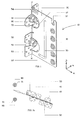
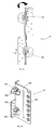
- FIG. 1 there is shown a schematic perspective view of a connector 10 according to a first preferred embodiment of the present invention.
- the connector 10 is a single cut sheet element for concealed joining of a first component 60, such as a timber beam or a post, to a second component 80, which may be for example a timber beam or joist extending perpendicularly therefrom (see Figure 3 ).
- the connector 10 may, for example, be a foundation (affixed to the floor or other substructure) on which a post is to be supported (not shown).
- Connector 10 has an attachment web 30, provided with through holes 31, and a locating slot 32, which in the depiction of Figure 1 has been folded about a bend line x-x so as to form a fastening flange 50 arranged substantially perpendicular thereto.
- An embossment 33 is provided to add strength and to help take up the space of the slot in order to prevent the attachment web 30 from "wobbling" in the slot.
- the fastening flange 50 comprises two slots 51, 52 each dimensioned to receive the shank of respective bolts 90 protruding from the second component (not shown), so as to permit rotation or twist of the connector 10 from a first connector insertion position where the shank of each bolt 90 protruding from the second component passes through the slot 51, 52 and is out of the plane x-y of the attachment web 30, to a second connector located position where the shank of each bolt 90 protruding from the second component passes through a slot 51, 52 and is in of the plane x-y of the attachment web 30, as shown.
- the attachment web 30 is also provided with, or is capable of having formed in it, two apertures 61, 62 dimensioned to receive the nuts 91 used with bolts 90.
- Fastening flange 50 is provided with optional through holes 53 for fasteners (e.g. nails), and a strengthening embossment 54 is provided which traverses the bend line x-x between attachment web 30 and fastening flange 50.
- embossments 33 and 54 provided on attachment web 30 are features known in the art from DlN 6932.
- One bead of embossment 33 runs parallel to fold or bending line x-x, and a further bead parallel to an edge.
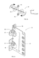
- FIGS 2a to 2c are schematic views of an installation sequence to achieve a connection using the connector of Figure 1 .
- Two bolts 90 are arranged in line in a substantially vertical spaced relationship so as to protrude from the second component (not shown).
- a nut 91 is provided on each bolt 90 and serves to provide a head behind which the sheet material of the connector 10 can be received.
- Connector 10 is offered up to a surface of the second component in a slanted from vertical orientation, as illustrated in Figure 2a , and inserted between the bolts 90 as illustrated in Figure 2b .
- the bolts 90 enter the respective slots 51, 52 of the fastening flange 50.
- attachment web 30 is inserted into a slot 82, generally on the end surface, of the first component 80 to be attached (depicted in certain Figures only for clarity), and fastened or held therein with fastening means such as dowels 95 or the like, which when installed extend through locating slot 32 and through holes 31.
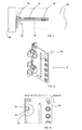
- All through holes 31 of attachment web 30 are crimped over at their edges. ln Figure 4e , the crimped sections of through holes 31 are denoted by the depth L which is shown proportionately to the thickness of material used for the connector 10.
- FIG. 7 there is shown a schematic side elevation view of a connector 110 according to a second preferred embodiment of the present invention in its flat form configuration before its fastening flange 150 is folded and bent out of the plane of the attachment web 130.
- the connector 110 is again a single cut sheet element for concealed joining of a first component 60, such as a timber beam or a post, to a second component 80, which may be for example a timber beam or joist extending perpendicularly therefrom (see Figures 7e and 7f ).
- the connector 110 may, for example, be a foundation (affixed to the floor or other substructure) on which a post is to be supported (not shown).
- Connector 110 has an attachment web 130, provided with through holes 131, and a locating slot 132.
- the attachment web 130 will be folded about a bend line x-x so as to form a fastening flange 150 arranged substantially perpendicular thereto.
- An embossment 133 is provided to add strength and to help take up the space of the slot in order to prevent the attachment web 130 from "wobbling" in the slot.
- the fastening flange 150 comprises two enclosed slots 151, 152 each dimensioned to receive the shank of respective bolts 190 protruding from the second component (not shown), so as to permit rotation or twist of the connector 110 from a first connector insertion position where the shank of each bolt 190 protruding from the second component passes through the enclosed slot 151, 152 and is out of the plane x-y of the attachment web 130, to a second connector located position where the shank of each bolt 190 protruding from the second component passes through the enclosed slot 151, 152 and is in of the plane x-y of the attachment web 130.
- the attachment web 130 is also provided with, or is capable of having formed in it, two apertures 161, 162 dimensioned to receive the nuts 191 used with bolts 190.
- Fastening flange 150 is provided with optional through holes 153 for fasteners (e.g. nails), and a strengthening embossment (not shown) may be provided which traverses the bend line x-x between attachment web 130 and fastening flange 150 (see Figure 7d ).
- Figures 7a to 7f are schematic views of an installation sequence to achieve a connection using the connector of Figure 7 .
- Two bolts 190 are arranged in line in a substantially vertical spaced relationship so as to protrude from the second component (not shown).
- a nut 191 is provided for each bolt 190 and later serves to provide a head behind which the sheet material of the connector 110 can be received.
- Connector 110 is offered up to a surface of the second component in a slanted from vertical orientation, as illustrated in Figure 7a , and inserted over the bolts 190 as illustrated in Figure 7a . Nuts 191 are then affixed to each bolt 190 to prevent withdrawal of the connector 110.
- attachment web 130 is inserted into a slot 182, generally on the end surface, of the first component 180 to be attached (depicted partially in Figure 7e for clarity), and fastened or held therein with fastening means such as dowels 195 or the like, which when installed extend through locating slot 132 and through holes 131.
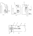
- FIG. 8 there is shown a schematic side elevation view of a connector 210 according to a third preferred embodiment of the present invention in its raw flat form configuration before its fastening flange 250 is folded and bent out of the plane of the attachment web 230.
- the connector 210 is again a single cut sheet element for concealed joining of a first component 60, such as a timber beam or a post, to a second component 80, which may be for example a timber beam or joist extending perpendicularly therefrom.
- the connector 210 may, for example, be a foundation (affixed to the floor or other substructure) on which a post is to be supported (not shown).
- Connector 210 has an attachment web 230, provided with through holes 231, and a locating slot 232.
- the attachment web 230 will be folded about a bend line x-x so as to form a fastening flange 250 arranged substantially perpendicular thereto.
- An embossment 233 is provided to add strength and to help take up the space of the slot in order to prevent the attachment web 230 from "wobbling" in the slot.
- the fastening flange 250 comprises one enclosed slot 251 and one open slot, 252 each dimensioned to receive the shank of a fastener.
- a bolt 290 is received in enclosed slot 251, and a nail or other suitable fastener 295 is received in open slot 252, both fasteners protruding from the second component (not shown), so as to permit rotation or twist of the connector 210 from a first connector insertion position where the shank of bolt 290 and fastener 295 protruding from the second component pass through the slots 251, 252 and out of the plane x-y of the attachment web 230, to a second connector located position where the shank of bolt 290 and fastener 295 protruding from the second component pass through the slots 251, 252 and in the plane x-y of the attachment web 230.
- the attachment web 230 is also provided with, or is capable of having formed in it, an aperture 261 dimensioned to receive the nut 291 used with bolt 290.
- Fastening flange 250 is provided with optional through holes 253 for fasteners (e.g. nails), and a strengthening embossment (not shown) may be provided which traverses the bend line x-x between attachment web 230 and fastening flange 250.
- a bolt 290 and a fastener 295 are arranged in line in a substantially vertical spaced relationship so as to protrude from the second component (not shown).
- a nut 291 is provided for bolt 290 and later serves to provide a head behind which the sheet material of the connector 210 can be received.
- Connector 210 is offered up to a surface of the second component in a slanted from vertical orientation and inserted over the bolt 290 and fastener 295. A nut 291 is then affixed to bolt 290 to prevent withdrawal of the connector 210.
- Connector 210 is then rotated or twisted about fastener 295 and bolt 290 enters the vertically extending portion of enclosed slot 251 of the fastening flange 250.
- the fastening flange 250 is retained behind respective nut 291 and head of fastener 295 which are then tightened or inserted further as appropriate.
- Optional fasteners e.g. nails
- attachment web 230 is inserted into a slot 282, generally on the end surface, of the first component to be attached, and fastened or held therein with fastening means such as dowels 295 or the like, which when installed extend through locating slot 232 and through holes 231.
- the connector 10, 110, 210 can be used not only as a perforated sheet-metal fitting for concealed beam attachment, but also as a post foot.
- connectors according to the present invention will be metallic and used in timber construction, the present invention is not limited as such.
- Connectors according to the present invention may be made from any suitable material and by any suitable manufacturing process, and may be formed from multiple parts or as a single part.
- the connectors according to the present invention may be used in any suitable connection application, e.g. concrete, brick, block, composites etc. and affixed using any suitable fasteners.
Landscapes
- Engineering & Computer Science (AREA)
- Architecture (AREA)
- Physics & Mathematics (AREA)
- Electromagnetism (AREA)
- Civil Engineering (AREA)
- Structural Engineering (AREA)
- Joining Of Building Structures In Genera (AREA)
- Snaps, Bayonet Connections, Set Pins, And Snap Rings (AREA)
Applications Claiming Priority (1)
| Application Number | Priority Date | Filing Date | Title |
|---|---|---|---|
| GBGB0914038.5A GB0914038D0 (en) | 2009-08-11 | 2009-08-11 | Connection |
Publications (3)
| Publication Number | Publication Date |
|---|---|
| EP2292856A2 true EP2292856A2 (fr) | 2011-03-09 |
| EP2292856A3 EP2292856A3 (fr) | 2012-10-24 |
| EP2292856B1 EP2292856B1 (fr) | 2014-12-03 |
Family
ID=41129985
Family Applications (1)
| Application Number | Title | Priority Date | Filing Date |
|---|---|---|---|
| EP10172473.0A Active EP2292856B1 (fr) | 2009-08-11 | 2010-08-11 | Connecteur |
Country Status (4)
| Country | Link |
|---|---|
| EP (1) | EP2292856B1 (fr) |
| ES (1) | ES2528031T3 (fr) |
| GB (2) | GB0914038D0 (fr) |
| PT (1) | PT2292856E (fr) |
Cited By (4)
| Publication number | Priority date | Publication date | Assignee | Title |
|---|---|---|---|---|
| CN106624678A (zh) * | 2016-12-14 | 2017-05-10 | 中国二十冶集团有限公司 | 一种模块化混凝土路面模板的制作方法 |
| NL2017629B1 (en) * | 2016-10-17 | 2018-04-24 | Scaldex Nederland B V | Anchoring device for anchoring a facade element to a building |
| US10422123B2 (en) | 2016-11-07 | 2019-09-24 | Simpson Strong-Tie Company Inc. | Concealed joist tie with sloped center flange |
| WO2021225935A1 (fr) * | 2020-05-04 | 2021-11-11 | Mitek Holdings, Inc | Connecteur structurel dissimulé |
Families Citing this family (5)
| Publication number | Priority date | Publication date | Assignee | Title |
|---|---|---|---|---|
| US9394680B2 (en) | 2013-12-14 | 2016-07-19 | Simpson Strong-Tie Company | Drywall joist hanger |
| JP6427120B2 (ja) * | 2016-01-27 | 2018-11-21 | 株式会社エヌ・シー・エヌ | 木造建築物の構造躯体の接合構造 |
| US11142902B2 (en) | 2017-06-07 | 2021-10-12 | Simpson Strong-Tie Company, Inc. | Drywall hanger |
| US11225787B2 (en) | 2018-06-06 | 2022-01-18 | Simpson Strong-Tie Company, Inc. | Drywall spacing joist hanger |
| US20250116105A1 (en) * | 2023-10-05 | 2025-04-10 | Simpson Strong-Tie Company Inc. | Notched moment frame connector system |
Citations (2)
| Publication number | Priority date | Publication date | Assignee | Title |
|---|---|---|---|---|
| DE9001067U1 (de) | 1990-01-31 | 1990-04-05 | GH - Baubeschläge Hartmann GmbH, 4970 Bad Oeynhausen | Verbinder für verdeckte Balkenanschlüsse |
| US5896721A (en) | 1996-11-19 | 1999-04-27 | West Company Limited | Metal device for joining wooden members in wooden building |
Family Cites Families (4)
| Publication number | Priority date | Publication date | Assignee | Title |
|---|---|---|---|---|
| US834462A (en) * | 1905-11-29 | 1906-10-30 | Oliver H Diffendarfer | Furniture-fastener. |
| DE9319125U1 (de) * | 1993-12-13 | 1994-02-24 | Bulldog Beratungs- und Vertriebsgesellschaft mbH, 28857 Syke | Verbindungselement zum Verbinden eines Holzbauteils mit einem zweiten Bauteil |
| JPH11152798A (ja) * | 1997-11-21 | 1999-06-08 | Sanko Techno Co Ltd | 木材接合金具 |
| JPH11280161A (ja) * | 1998-03-27 | 1999-10-12 | Hiroki Kanai | 梁受け金具 |
-
2009
- 2009-08-11 GB GBGB0914038.5A patent/GB0914038D0/en not_active Ceased
-
2010
- 2010-08-10 GB GB1013431.0A patent/GB2472692B/en active Active
- 2010-08-11 EP EP10172473.0A patent/EP2292856B1/fr active Active
- 2010-08-11 ES ES10172473.0T patent/ES2528031T3/es active Active
- 2010-08-11 PT PT101724730T patent/PT2292856E/pt unknown
Patent Citations (2)
| Publication number | Priority date | Publication date | Assignee | Title |
|---|---|---|---|---|
| DE9001067U1 (de) | 1990-01-31 | 1990-04-05 | GH - Baubeschläge Hartmann GmbH, 4970 Bad Oeynhausen | Verbinder für verdeckte Balkenanschlüsse |
| US5896721A (en) | 1996-11-19 | 1999-04-27 | West Company Limited | Metal device for joining wooden members in wooden building |
Cited By (6)
| Publication number | Priority date | Publication date | Assignee | Title |
|---|---|---|---|---|
| NL2017629B1 (en) * | 2016-10-17 | 2018-04-24 | Scaldex Nederland B V | Anchoring device for anchoring a facade element to a building |
| US10422123B2 (en) | 2016-11-07 | 2019-09-24 | Simpson Strong-Tie Company Inc. | Concealed joist tie with sloped center flange |
| CN106624678A (zh) * | 2016-12-14 | 2017-05-10 | 中国二十冶集团有限公司 | 一种模块化混凝土路面模板的制作方法 |
| WO2021225935A1 (fr) * | 2020-05-04 | 2021-11-11 | Mitek Holdings, Inc | Connecteur structurel dissimulé |
| US11525255B2 (en) | 2020-05-04 | 2022-12-13 | Columbia Insurance Company | Concealed structural connector |
| US12590453B2 (en) | 2020-05-04 | 2026-03-31 | Columbia Insurance Company | Concealed structural connector |
Also Published As
| Publication number | Publication date |
|---|---|
| EP2292856A3 (fr) | 2012-10-24 |
| GB201013431D0 (en) | 2010-09-22 |
| ES2528031T3 (es) | 2015-02-03 |
| GB2472692B (en) | 2012-02-01 |
| PT2292856E (pt) | 2015-02-13 |
| GB0914038D0 (en) | 2009-09-16 |
| EP2292856B1 (fr) | 2014-12-03 |
| GB2472692A (en) | 2011-02-16 |
Similar Documents
| Publication | Publication Date | Title |
|---|---|---|
| EP2292856B1 (fr) | Connecteur | |
| US20240093481A1 (en) | Hanger for fire separation wall | |
| CA2970646C (fr) | Support robuste destine a un mur de separation incendie | |
| US8590255B2 (en) | Bridging connector | |
| AU2017204808B2 (en) | Teardrop and offset notch bridging connector | |
| US9109361B2 (en) | Bracing bridging member | |
| WO2008054810A2 (fr) | Guide-clou doté d'une ouverture curviligne | |
| EP1760214B1 (fr) | Ancrage de poutre | |
| US20230332395A1 (en) | Heavy Seat Knife Plate Hanger | |
| AU2015200512B2 (en) | Bracing bridging member | |
| US20100189496A1 (en) | Timber connectors and noggings | |
| CA3248238A1 (fr) | Produit de bardage plat à écart de nickel avec joint de verrouillage | |
| KR20220025796A (ko) | 경량철골용 사각파이프 연결구 및 이를 이용한 사각 파이프 연결방법 | |
| JP3082134U (ja) | 筋交い用固定金具 | |
| GB2541174A (en) | Apparatus and method for the construction of a portal frame | |
| EP4153822B1 (fr) | Connecteur pour construction à sec, arrangement pour construction à sec, kit et méthode de construction d'un plafond pour construction à sec | |
| WO2025242798A1 (fr) | Ensemble de fixation pour relier des composants de construction | |
| JP5406656B2 (ja) | L形アングル取付具及びl形アングルの取付構造 | |
| JP3839198B2 (ja) | 外壁パネルの固定金具 | |
| NZ704454B2 (en) | Bracing bridging member | |
| GB2500030A (en) | Bracing element for a joist or truss | |
| GB2455103A (en) | Installation aid for a joist hanger |
Legal Events
| Date | Code | Title | Description |
|---|---|---|---|
| PUAI | Public reference made under article 153(3) epc to a published international application that has entered the european phase |
Free format text: ORIGINAL CODE: 0009012 |
|
| AK | Designated contracting states |
Kind code of ref document: A2 Designated state(s): AL AT BE BG CH CY CZ DE DK EE ES FI FR GB GR HR HU IE IS IT LI LT LU LV MC MK MT NL NO PL PT RO SE SI SK SM TR |
|
| AX | Request for extension of the european patent |
Extension state: BA ME RS |
|
| PUAL | Search report despatched |
Free format text: ORIGINAL CODE: 0009013 |
|
| AK | Designated contracting states |
Kind code of ref document: A3 Designated state(s): AL AT BE BG CH CY CZ DE DK EE ES FI FR GB GR HR HU IE IS IT LI LT LU LV MC MK MT NL NO PL PT RO SE SI SK SM TR |
|
| AX | Request for extension of the european patent |
Extension state: BA ME RS |
|
| RIC1 | Information provided on ipc code assigned before grant |
Ipc: E04B 1/26 20060101AFI20120920BHEP |
|
| 17P | Request for examination filed |
Effective date: 20130424 |
|
| GRAP | Despatch of communication of intention to grant a patent |
Free format text: ORIGINAL CODE: EPIDOSNIGR1 |
|
| INTG | Intention to grant announced |
Effective date: 20140304 |
|
| GRAS | Grant fee paid |
Free format text: ORIGINAL CODE: EPIDOSNIGR3 |
|
| GRAA | (expected) grant |
Free format text: ORIGINAL CODE: 0009210 |
|
| AK | Designated contracting states |
Kind code of ref document: B1 Designated state(s): AL AT BE BG CH CY CZ DE DK EE ES FI FR GB GR HR HU IE IS IT LI LT LU LV MC MK MT NL NO PL PT RO SE SI SK SM TR |
|
| REG | Reference to a national code |
Ref country code: GB Ref legal event code: FG4D |
|
| REG | Reference to a national code |
Ref country code: AT Ref legal event code: REF Ref document number: 699473 Country of ref document: AT Kind code of ref document: T Effective date: 20141215 Ref country code: CH Ref legal event code: EP |
|
| REG | Reference to a national code |
Ref country code: IE Ref legal event code: FG4D |
|
| REG | Reference to a national code |
Ref country code: DE Ref legal event code: R096 Ref document number: 602010020656 Country of ref document: DE Effective date: 20150115 |
|
| REG | Reference to a national code |
Ref country code: ES Ref legal event code: FG2A Ref document number: 2528031 Country of ref document: ES Kind code of ref document: T3 Effective date: 20150203 |
|
| REG | Reference to a national code |
Ref country code: PT Ref legal event code: SC4A Free format text: AVAILABILITY OF NATIONAL TRANSLATION Effective date: 20150209 |
|
| REG | Reference to a national code |
Ref country code: NL Ref legal event code: T3 |
|
| REG | Reference to a national code |
Ref country code: AT Ref legal event code: MK05 Ref document number: 699473 Country of ref document: AT Kind code of ref document: T Effective date: 20141203 |
|
| PG25 | Lapsed in a contracting state [announced via postgrant information from national office to epo] |
Ref country code: NO Free format text: LAPSE BECAUSE OF FAILURE TO SUBMIT A TRANSLATION OF THE DESCRIPTION OR TO PAY THE FEE WITHIN THE PRESCRIBED TIME-LIMIT Effective date: 20150303 Ref country code: LT Free format text: LAPSE BECAUSE OF FAILURE TO SUBMIT A TRANSLATION OF THE DESCRIPTION OR TO PAY THE FEE WITHIN THE PRESCRIBED TIME-LIMIT Effective date: 20141203 Ref country code: FI Free format text: LAPSE BECAUSE OF FAILURE TO SUBMIT A TRANSLATION OF THE DESCRIPTION OR TO PAY THE FEE WITHIN THE PRESCRIBED TIME-LIMIT Effective date: 20141203 |
|
| REG | Reference to a national code |
Ref country code: LT Ref legal event code: MG4D |
|
| PG25 | Lapsed in a contracting state [announced via postgrant information from national office to epo] |
Ref country code: GR Free format text: LAPSE BECAUSE OF FAILURE TO SUBMIT A TRANSLATION OF THE DESCRIPTION OR TO PAY THE FEE WITHIN THE PRESCRIBED TIME-LIMIT Effective date: 20150304 Ref country code: AT Free format text: LAPSE BECAUSE OF FAILURE TO SUBMIT A TRANSLATION OF THE DESCRIPTION OR TO PAY THE FEE WITHIN THE PRESCRIBED TIME-LIMIT Effective date: 20141203 Ref country code: LV Free format text: LAPSE BECAUSE OF FAILURE TO SUBMIT A TRANSLATION OF THE DESCRIPTION OR TO PAY THE FEE WITHIN THE PRESCRIBED TIME-LIMIT Effective date: 20141203 Ref country code: CY Free format text: LAPSE BECAUSE OF FAILURE TO SUBMIT A TRANSLATION OF THE DESCRIPTION OR TO PAY THE FEE WITHIN THE PRESCRIBED TIME-LIMIT Effective date: 20141203 Ref country code: HR Free format text: LAPSE BECAUSE OF FAILURE TO SUBMIT A TRANSLATION OF THE DESCRIPTION OR TO PAY THE FEE WITHIN THE PRESCRIBED TIME-LIMIT Effective date: 20141203 Ref country code: SE Free format text: LAPSE BECAUSE OF FAILURE TO SUBMIT A TRANSLATION OF THE DESCRIPTION OR TO PAY THE FEE WITHIN THE PRESCRIBED TIME-LIMIT Effective date: 20141203 |
|
| PG25 | Lapsed in a contracting state [announced via postgrant information from national office to epo] |
Ref country code: CZ Free format text: LAPSE BECAUSE OF FAILURE TO SUBMIT A TRANSLATION OF THE DESCRIPTION OR TO PAY THE FEE WITHIN THE PRESCRIBED TIME-LIMIT Effective date: 20141203 Ref country code: RO Free format text: LAPSE BECAUSE OF FAILURE TO SUBMIT A TRANSLATION OF THE DESCRIPTION OR TO PAY THE FEE WITHIN THE PRESCRIBED TIME-LIMIT Effective date: 20141203 Ref country code: EE Free format text: LAPSE BECAUSE OF FAILURE TO SUBMIT A TRANSLATION OF THE DESCRIPTION OR TO PAY THE FEE WITHIN THE PRESCRIBED TIME-LIMIT Effective date: 20141203 Ref country code: SK Free format text: LAPSE BECAUSE OF FAILURE TO SUBMIT A TRANSLATION OF THE DESCRIPTION OR TO PAY THE FEE WITHIN THE PRESCRIBED TIME-LIMIT Effective date: 20141203 |
|
| PG25 | Lapsed in a contracting state [announced via postgrant information from national office to epo] |
Ref country code: IS Free format text: LAPSE BECAUSE OF FAILURE TO SUBMIT A TRANSLATION OF THE DESCRIPTION OR TO PAY THE FEE WITHIN THE PRESCRIBED TIME-LIMIT Effective date: 20150403 Ref country code: PL Free format text: LAPSE BECAUSE OF FAILURE TO SUBMIT A TRANSLATION OF THE DESCRIPTION OR TO PAY THE FEE WITHIN THE PRESCRIBED TIME-LIMIT Effective date: 20141203 |
|
| REG | Reference to a national code |
Ref country code: DE Ref legal event code: R097 Ref document number: 602010020656 Country of ref document: DE |
|
| PLBE | No opposition filed within time limit |
Free format text: ORIGINAL CODE: 0009261 |
|
| STAA | Information on the status of an ep patent application or granted ep patent |
Free format text: STATUS: NO OPPOSITION FILED WITHIN TIME LIMIT |
|
| PG25 | Lapsed in a contracting state [announced via postgrant information from national office to epo] |
Ref country code: DK Free format text: LAPSE BECAUSE OF FAILURE TO SUBMIT A TRANSLATION OF THE DESCRIPTION OR TO PAY THE FEE WITHIN THE PRESCRIBED TIME-LIMIT Effective date: 20141203 |
|
| 26N | No opposition filed |
Effective date: 20150904 |
|
| PG25 | Lapsed in a contracting state [announced via postgrant information from national office to epo] |
Ref country code: IT Free format text: LAPSE BECAUSE OF FAILURE TO SUBMIT A TRANSLATION OF THE DESCRIPTION OR TO PAY THE FEE WITHIN THE PRESCRIBED TIME-LIMIT Effective date: 20141203 |
|
| PG25 | Lapsed in a contracting state [announced via postgrant information from national office to epo] |
Ref country code: SI Free format text: LAPSE BECAUSE OF FAILURE TO SUBMIT A TRANSLATION OF THE DESCRIPTION OR TO PAY THE FEE WITHIN THE PRESCRIBED TIME-LIMIT Effective date: 20141203 |
|
| REG | Reference to a national code |
Ref country code: DE Ref legal event code: R119 Ref document number: 602010020656 Country of ref document: DE |
|
| REG | Reference to a national code |
Ref country code: CH Ref legal event code: PL |
|
| PG25 | Lapsed in a contracting state [announced via postgrant information from national office to epo] |
Ref country code: CH Free format text: LAPSE BECAUSE OF NON-PAYMENT OF DUE FEES Effective date: 20150831 Ref country code: LI Free format text: LAPSE BECAUSE OF NON-PAYMENT OF DUE FEES Effective date: 20150831 |
|
| REG | Reference to a national code |
Ref country code: IE Ref legal event code: MM4A |
|
| PG25 | Lapsed in a contracting state [announced via postgrant information from national office to epo] |
Ref country code: IE Free format text: LAPSE BECAUSE OF NON-PAYMENT OF DUE FEES Effective date: 20150811 Ref country code: DE Free format text: LAPSE BECAUSE OF NON-PAYMENT OF DUE FEES Effective date: 20160301 |
|
| REG | Reference to a national code |
Ref country code: FR Ref legal event code: PLFP Year of fee payment: 7 |
|
| PG25 | Lapsed in a contracting state [announced via postgrant information from national office to epo] |
Ref country code: MT Free format text: LAPSE BECAUSE OF FAILURE TO SUBMIT A TRANSLATION OF THE DESCRIPTION OR TO PAY THE FEE WITHIN THE PRESCRIBED TIME-LIMIT Effective date: 20141203 |
|
| PG25 | Lapsed in a contracting state [announced via postgrant information from national office to epo] |
Ref country code: BG Free format text: LAPSE BECAUSE OF FAILURE TO SUBMIT A TRANSLATION OF THE DESCRIPTION OR TO PAY THE FEE WITHIN THE PRESCRIBED TIME-LIMIT Effective date: 20141203 Ref country code: HU Free format text: LAPSE BECAUSE OF FAILURE TO SUBMIT A TRANSLATION OF THE DESCRIPTION OR TO PAY THE FEE WITHIN THE PRESCRIBED TIME-LIMIT; INVALID AB INITIO Effective date: 20100811 Ref country code: SM Free format text: LAPSE BECAUSE OF FAILURE TO SUBMIT A TRANSLATION OF THE DESCRIPTION OR TO PAY THE FEE WITHIN THE PRESCRIBED TIME-LIMIT Effective date: 20141203 |
|
| REG | Reference to a national code |
Ref country code: FR Ref legal event code: PLFP Year of fee payment: 8 |
|
| PG25 | Lapsed in a contracting state [announced via postgrant information from national office to epo] |
Ref country code: TR Free format text: LAPSE BECAUSE OF FAILURE TO SUBMIT A TRANSLATION OF THE DESCRIPTION OR TO PAY THE FEE WITHIN THE PRESCRIBED TIME-LIMIT Effective date: 20141203 |
|
| PGFP | Annual fee paid to national office [announced via postgrant information from national office to epo] |
Ref country code: GB Payment date: 20170830 Year of fee payment: 10 |
|
| PGFP | Annual fee paid to national office [announced via postgrant information from national office to epo] |
Ref country code: MC Payment date: 20170818 Year of fee payment: 8 |
|
| PGFP | Annual fee paid to national office [announced via postgrant information from national office to epo] |
Ref country code: PT Payment date: 20170713 Year of fee payment: 8 |
|
| PG25 | Lapsed in a contracting state [announced via postgrant information from national office to epo] |
Ref country code: MK Free format text: LAPSE BECAUSE OF FAILURE TO SUBMIT A TRANSLATION OF THE DESCRIPTION OR TO PAY THE FEE WITHIN THE PRESCRIBED TIME-LIMIT Effective date: 20141203 |
|
| REG | Reference to a national code |
Ref country code: FR Ref legal event code: PLFP Year of fee payment: 9 |
|
| PG25 | Lapsed in a contracting state [announced via postgrant information from national office to epo] |
Ref country code: AL Free format text: LAPSE BECAUSE OF FAILURE TO SUBMIT A TRANSLATION OF THE DESCRIPTION OR TO PAY THE FEE WITHIN THE PRESCRIBED TIME-LIMIT Effective date: 20141203 |
|
| PG25 | Lapsed in a contracting state [announced via postgrant information from national office to epo] |
Ref country code: MC Free format text: LAPSE BECAUSE OF NON-PAYMENT OF DUE FEES Effective date: 20180831 |
|
| GBPC | Gb: european patent ceased through non-payment of renewal fee |
Effective date: 20180811 |
|
| PG25 | Lapsed in a contracting state [announced via postgrant information from national office to epo] |
Ref country code: LU Free format text: LAPSE BECAUSE OF NON-PAYMENT OF DUE FEES Effective date: 20180811 |
|
| PG25 | Lapsed in a contracting state [announced via postgrant information from national office to epo] |
Ref country code: PT Free format text: LAPSE BECAUSE OF NON-PAYMENT OF DUE FEES Effective date: 20190211 |
|
| PG25 | Lapsed in a contracting state [announced via postgrant information from national office to epo] |
Ref country code: GB Free format text: LAPSE BECAUSE OF NON-PAYMENT OF DUE FEES Effective date: 20180811 |
|
| PGFP | Annual fee paid to national office [announced via postgrant information from national office to epo] |
Ref country code: NL Payment date: 20250828 Year of fee payment: 16 |
|
| PGFP | Annual fee paid to national office [announced via postgrant information from national office to epo] |
Ref country code: ES Payment date: 20250909 Year of fee payment: 16 |
|
| PGFP | Annual fee paid to national office [announced via postgrant information from national office to epo] |
Ref country code: BE Payment date: 20250828 Year of fee payment: 16 |
|
| PGFP | Annual fee paid to national office [announced via postgrant information from national office to epo] |
Ref country code: FR Payment date: 20250829 Year of fee payment: 16 |