EP2292896A2 - Moteur à combustion interne à piston rotatif - Google Patents
Moteur à combustion interne à piston rotatif Download PDFInfo
- Publication number
- EP2292896A2 EP2292896A2 EP20100166901 EP10166901A EP2292896A2 EP 2292896 A2 EP2292896 A2 EP 2292896A2 EP 20100166901 EP20100166901 EP 20100166901 EP 10166901 A EP10166901 A EP 10166901A EP 2292896 A2 EP2292896 A2 EP 2292896A2
- Authority
- EP
- European Patent Office
- Prior art keywords
- disc
- combustion engine
- internal combustion
- shaft
- rotary piston
- Prior art date
- Legal status (The legal status is an assumption and is not a legal conclusion. Google has not performed a legal analysis and makes no representation as to the accuracy of the status listed.)
- Withdrawn
Links
- 238000002485 combustion reaction Methods 0.000 title claims abstract description 41
- 238000007906 compression Methods 0.000 claims description 50
- 230000006835 compression Effects 0.000 claims description 48
- 239000000203 mixture Substances 0.000 claims description 25
- 230000001360 synchronised effect Effects 0.000 claims description 3
- XLYOFNOQVPJJNP-UHFFFAOYSA-N water Substances O XLYOFNOQVPJJNP-UHFFFAOYSA-N 0.000 claims description 3
- 238000005096 rolling process Methods 0.000 claims 5
- 230000007704 transition Effects 0.000 claims 5
- 229910010293 ceramic material Inorganic materials 0.000 claims 1
- 239000003779 heat-resistant material Substances 0.000 claims 1
- 239000007789 gas Substances 0.000 description 18
- 239000000446 fuel Substances 0.000 description 5
- 238000011161 development Methods 0.000 description 4
- 230000018109 developmental process Effects 0.000 description 4
- 238000010276 construction Methods 0.000 description 3
- 238000006073 displacement reaction Methods 0.000 description 2
- 238000000034 method Methods 0.000 description 2
- TVMXDCGIABBOFY-UHFFFAOYSA-N octane Chemical compound CCCCCCCC TVMXDCGIABBOFY-UHFFFAOYSA-N 0.000 description 2
- 238000005192 partition Methods 0.000 description 2
- 230000002093 peripheral effect Effects 0.000 description 2
- 239000011819 refractory material Substances 0.000 description 2
- LFQSCWFLJHTTHZ-UHFFFAOYSA-N Ethanol Chemical compound CCO LFQSCWFLJHTTHZ-UHFFFAOYSA-N 0.000 description 1
- 239000000919 ceramic Substances 0.000 description 1
- 238000005056 compaction Methods 0.000 description 1
- 238000001816 cooling Methods 0.000 description 1
- 230000008878 coupling Effects 0.000 description 1
- 238000010168 coupling process Methods 0.000 description 1
- 238000005859 coupling reaction Methods 0.000 description 1
- 230000000694 effects Effects 0.000 description 1
- 238000010304 firing Methods 0.000 description 1
- 238000002347 injection Methods 0.000 description 1
- 239000007924 injection Substances 0.000 description 1
- 238000005461 lubrication Methods 0.000 description 1
- 239000000463 material Substances 0.000 description 1
Images




Classifications
-
- F—MECHANICAL ENGINEERING; LIGHTING; HEATING; WEAPONS; BLASTING
- F01—MACHINES OR ENGINES IN GENERAL; ENGINE PLANTS IN GENERAL; STEAM ENGINES
- F01C—ROTARY-PISTON OR OSCILLATING-PISTON MACHINES OR ENGINES
- F01C1/00—Rotary-piston machines or engines
- F01C1/08—Rotary-piston machines or engines of intermeshing engagement type, i.e. with engagement of co- operating members similar to that of toothed gearing
- F01C1/12—Rotary-piston machines or engines of intermeshing engagement type, i.e. with engagement of co- operating members similar to that of toothed gearing of other than internal-axis type
- F01C1/123—Rotary-piston machines or engines of intermeshing engagement type, i.e. with engagement of co- operating members similar to that of toothed gearing of other than internal-axis type with tooth-like elements, extending generally radially from the rotor body cooperating with recesses in the other rotor, e.g. one tooth
-
- F—MECHANICAL ENGINEERING; LIGHTING; HEATING; WEAPONS; BLASTING
- F01—MACHINES OR ENGINES IN GENERAL; ENGINE PLANTS IN GENERAL; STEAM ENGINES
- F01C—ROTARY-PISTON OR OSCILLATING-PISTON MACHINES OR ENGINES
- F01C11/00—Combinations of two or more machines or engines, each being of rotary-piston or oscillating-piston type
- F01C11/002—Combinations of two or more machines or engines, each being of rotary-piston or oscillating-piston type of similar working principle
-
- F—MECHANICAL ENGINEERING; LIGHTING; HEATING; WEAPONS; BLASTING
- F05—INDEXING SCHEMES RELATING TO ENGINES OR PUMPS IN VARIOUS SUBCLASSES OF CLASSES F01-F04
- F05C—INDEXING SCHEME RELATING TO MATERIALS, MATERIAL PROPERTIES OR MATERIAL CHARACTERISTICS FOR MACHINES, ENGINES OR PUMPS OTHER THAN NON-POSITIVE-DISPLACEMENT MACHINES OR ENGINES
- F05C2203/00—Non-metallic inorganic materials
- F05C2203/08—Ceramics; Oxides
Definitions
- the invention relates to a rotary piston internal combustion engine.
- Rotary piston internal combustion engines are known in numerous designs. So revealed the DE 2 218 132 A1 a rotary piston internal combustion engine in which a plurality of individual units are assembled in tandem design. Each of the units consists of two circular rotary pistons mounted on parallel shafts, each of which is provided over a part of its circumference with a recess in the form of a circular ring section resulting from meshing engagement with a piston of one unit as the compression space and with the other piston of the same unit serves as an expansion or work space. In this case, each unit of two circular rotary pistons is enclosed by a housing that consists of two side walls and a jacket, which has the shape of two intersecting circles in the axial normal section.
- the individual housings of the individual units must be arranged side by side. Between the compression space of a unit and the expansion space of a second unit arranged next to this unit, a connecting line is provided in order to be able to move the fuel-air mixture generated and compressed in the one compression space via the connecting line into the expansion space of the adjacent unit.
- This design has the disadvantage that the connection of several units to a multi-cylinder rotary piston internal combustion engine in the axial direction takes up much space, so that a multi-cylinder rotary piston internal combustion engine builds relatively wide in the axial direction. Also, each case the housing of the individual units must be sealed, which means a considerable effort.
- DE 43 23 345 C2 discloses a rotary piston internal combustion engine with two substantially equal, round, mutually perpendicular discs which rotate about mutually perpendicular axes of rotation. This results in disadvantageously high axial forces.
- the invention is therefore based on the object to provide a rotary piston internal combustion engine, which overcomes the disadvantages mentioned above and in particular allows a compact, powerful and easy-to-seal construction and energy-saving operation.
- An in Fig. 1 to 3 schematically illustrated rotary piston internal combustion engine has as essential components six substantially identical slices 1 to 6.
- the discs 1 and 5 are also referred to as intake-side outer discs, while the discs 2 and 6 are also referred to as output-side outer discs.
- the discs 3 and 4 are also referred to as middle, inlet or driven side discs.
- the disks 1 to 6 basically consist of circular disks, which have a piston region of larger diameter and an intermediate region of smaller diameter, as seen from Fig. 2 evident. The two areas each occupy about half of the slices 1 to 6.
- the discs 1, 3 and 5 are mounted on a shaft 7, while the discs 2, 4 and 6 are arranged on an output shaft 8. Both shafts 7, 8 rotate in opposite directions in the motor operation in the Fig. 2 shown directions, the shaft 7 thus counterclockwise and the output shaft 8 in a clockwise direction. In order to ensure a synchronous running of the shafts 7, 8, they have in Fig. 1 to 3 not shown, intermeshing gears, which ensure a coupling in the rotation ratio 1: 1.
- the discs 1 and 2, 3 and 4 and 5 and 6 respectively form mutually associated pairs of discs.
- the intermediate regions and piston regions of the associated pairs of disks are arranged on the shaft 7 and the output shaft 8 so that they engage with each other in meshing engagement.
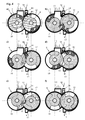
- inner discs 3 and 4 On the basis of in Fig. 2 completely visible inner discs 3 and 4 is easily seen that during approximately half an opposite rotation of the two discs 3 and 4, the inner periphery of the intermediate portion of the inlet side disc 3 on the outer circumference of the piston portion of the driven-side disc 4 rolls (in Fig. 1-3 and 4a, b and f shown).
- the inner circumference of the intermediate portion of the driven side pulley 4 rolls on the outer periphery of the piston portion of the intake side pulley 3 (in FIG Fig. 4 ce shown).
- the disks 1 to 6 are surrounded by a housing 9, which consists essentially of two interconnected on their longitudinal sides sub-cylinders.
- a compression cylinder 10 part cylinder is above a reaching over all discs 1, 3, 5 inlet opening 11 for a fuel-air mixture.
- the expansion cylinder 12 designated partial cylinder is located below a only in the region of the outer discs 2, 6 extending outlet 13 for the combusted fuel-air mixture, in the region of the middle disc 4 runs this sealingly on the expansion cylinder 12 from.
- connection channel entrances 15 at the bottom on the front-side outer sides of the compression cylinder 10, while a connecting channel exit 16 in the circulation area of the expansion-side central disc 4 extends into the expansion cylinder 12.
- the connection channel inputs 15 are also denoted by RLO, the connection channel output 16 also by VKA.
- spark plug 18 In order to ignite the fuel-air mixture, which is compressed in the compression cylinder 10 and the connecting channel 14, 14 spark plugs 17 and in the region of the connecting channel output 16, a spark plug 18 are provided in the region of the connecting channel inputs.
- Fig. 4 a shows the position of the discs 1-4 at the beginning of a cycle.
- the inlet opening 11 is closed in the region of the discs 1 and 5, while it is open in the region of the central inlet-side disc 4 for the intake of fuel-air mixture.
- connection channel inputs 15 are opened, while the connection channel outlet 16 is closed by the expansion-side central disc 4.
- connection channel outlet 16 is closed by the expansion-side central disc 4.
- the expansion phase ends in the region of the outer disks 2 and 6, which still close the outlet 13.
- the burned exhaust gases in the area of Intermediate portion of the central disc 4 are slidably displaced in the direction of the outlet 13 and thus throttled to the outlet 13.
- the outlet 13 through the windows 2 and 6 increase open, the exhaust gases in the region of the discs 2, 4 6 are throttled out to the outlet 13 and discharged there.
- connection channel inputs 15 are - starting with Fig. 4c) - Then closed by the outer discs 1 and 5, so that the compression process by the Slices 1 and 5 is completed.
- the connecting channel output 16 is released in the expansion cylinder 12 through the middle disc 4, so that the compressed fuel-air mixture can get into the expansion cylinder 12.
- the still in the connecting channel 14 located compressed fuel-air mixture is ignited by the spark plugs 17 and 18, so initially only a combustion takes place in the region of the connecting channel 14 and the intermediate region of the middle disc 4 and thus only this is driven.
- the control of the rotary piston internal combustion engine can take place, inter alia, by controlling the fuel supply, controlling the ignition timing and controlling the compression.
- Fig. 5 a) to 5 c) It is shown how a different compression can be set by a different control angle ⁇ at the ignition time.
- the adjustable firing angle ⁇ is achieved in that the middle disc pair 3, 4 is rotated relative to the outer disc pairs 1.5 and 2, 6. So is in Fig. 5 a) shown a small ignition angle ⁇ , in which the fuel is less compressed than, for example, in Fig. 5 b) or Fig. 5 c) , In the Fig. 5 a) shown position is suitable for light fuels such as alcohol, gases, etc.
- the control angle ⁇ is after Fig. 5b) suitable for heavy fuels such as high octane gasoline in Fig. 5c) suitable control angle ⁇ makes sense.
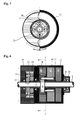
- Fig. 6 only the structure of the expansion cylinder 12 is shown, the compression cylinder is formed accordingly.
- a control block 19 is mounted to the in Fig. 6 left end face of the expansion cylinder 12.
- the output shaft 8 extends through both the expansion cylinder 12 and the control block 19 and is there rotatably mounted respectively via ball bearings 20, 21.
- a gear 22 is fixedly connected to the output shaft 8, wherein the gear 22 engages in a corresponding gear on the shaft 7 and thus ensures the synchronous running of the shafts 7, 8.
- the gear 22 can be connected via screw 23 fixed to a second, equally trained gear 24.
- the second gear 24 is fixedly connected to a control sleeve 25.
- the control sleeve 25 has the in Fig. 6 shown cross section and is rotatably mounted relative to the output shaft 8 by means of ball bearings 26, 27 on the expansion cylinder 12 and its housing mounted. On the control sleeve 25 in turn, the outer disc 2 and 6 are fixed. In this case, the control sleeve 25 in the region of the disc 2, a hollow cylindrical recess 28 into which a mounted on the output shaft 8 corresponding annular control disk 29 extends. From the control disk 29 rich control bolt 30 in Fig. 7 recognizable bean-shaped, elongated openings 31 in the one side wall of the hollow cylindrical recess 28 of the control sleeve 25. The control pin 30 extend into corresponding holes in the middle disc 4th
- the output shaft 8 can be rotated relative to the control sleeve 25 by the control angle ⁇ , which is limited by the length of the openings 31.
- the control angle ⁇ is limited by the length of the openings 31.
- the control angle ⁇ has to be set, and then the gears 22 and 24 have to be firmly connected again.
- numerous threaded holes can be arranged, in which the connecting screws 23 of the gear 22 can be used differently.
- the control angle ⁇ between the middle pair of disks 3,4 and the outer disk pairs 1, 2 and 5, 6 can be changed in a fast manner.
- gears 24 and the corresponding gear on the shaft 7 can also be replaced by discs which are not related to each other.
- the synchronization of the shafts 7, 8 then takes place via the gear 22 and the meshing with this gear on the shaft. 7
- an additional inlet 32 may be provided in the expansion area of the expansion cylinder 12, through which a certain amount of water can be introduced into the expansion area.
- FIGS. 9 and 10 an alternative embodiment of the rotary piston internal combustion engine is shown. This is different from the one in Fig. 1 to 7 shown embodiment in that instead of three pairs of discs 1,2, 3,4 and 5,6 only two pairs of discs 1,2 and 3,4 are used, the pair of discs 5, 6 from Fig. 1 was omitted. Otherwise, the structure and functioning of the in FIGS. 9 and 10 shown rotary piston internal combustion engine of the rotary piston internal combustion engine with three disc pairs in Fig.
- the embodiment with three disc pairs 1,2, 3,4 and 5,6 has the advantage that the symmetrical design with two outer disc pairs 2, 1 and 5 , 6 an asymmetrical load distribution as in the embodiment in FIGS. 9 and 10 is avoided.
- FIGS. 9 and 10 arising pulsating axial forces, which lead to significantly higher friction of the side surfaces of the discs to each other and the housing can be avoided.
- the rotary piston internal combustion engine is preferably made of refractory materials, such as ceramics. In particular, this applies to the discs 1-6 and the inner walls of the compression and expansion cylinders 10, 12. When using such refractory materials very high temperatures in the expansion space can be achieved, the rotary piston internal combustion engine then can operate largely without additional cooling in operation. Alternatively or in combination, however, conventional materials used in engine construction can also be used.
- the expansion forces generated are completely transferred to the working shaft 8.
- the rotary piston internal combustion engine according to the invention runs wear-free, lubrication is not necessary, eliminating all the problems associated with the oil supply, oil pressure and oil temperature control in conventional engines.
- the rotary piston internal combustion engine according to the invention has no valves, camshafts, toothed belts, toothed chains, pulleys, oil sump or partitions.
- the largest torque is generated at the ignition.
- the ignition of the spark plugs 17, 18 at the connection channel input 15 or connection channel output 16 can also be controlled differently in order, for example, to achieve direction-controlled combustion from the connection channel inputs 15 to the connection channel output 16.
Landscapes
- Engineering & Computer Science (AREA)
- Mechanical Engineering (AREA)
- General Engineering & Computer Science (AREA)
- Combustion Methods Of Internal-Combustion Engines (AREA)
Applications Claiming Priority (1)
| Application Number | Priority Date | Filing Date | Title |
|---|---|---|---|
| DE200910033672 DE102009033672B4 (de) | 2009-07-17 | 2009-07-17 | Drehkolben-Brennkraftmaschine |
Publications (2)
| Publication Number | Publication Date |
|---|---|
| EP2292896A2 true EP2292896A2 (fr) | 2011-03-09 |
| EP2292896A3 EP2292896A3 (fr) | 2013-08-07 |
Family
ID=42937126
Family Applications (1)
| Application Number | Title | Priority Date | Filing Date |
|---|---|---|---|
| EP20100166901 Withdrawn EP2292896A3 (fr) | 2009-07-17 | 2010-06-22 | Moteur à combustion interne à piston rotatif |
Country Status (2)
| Country | Link |
|---|---|
| EP (1) | EP2292896A3 (fr) |
| DE (1) | DE102009033672B4 (fr) |
Cited By (3)
| Publication number | Priority date | Publication date | Assignee | Title |
|---|---|---|---|---|
| WO2014122289A1 (fr) * | 2013-02-07 | 2014-08-14 | Rb Holding Gmbh | Moteur à pistons rotatifs |
| WO2021176110A3 (fr) * | 2019-04-29 | 2021-11-11 | Munoz Saiz Manuel | Moteur rotatif à combustion interne |
| WO2022214716A1 (fr) * | 2021-04-05 | 2022-10-13 | Munoz Saiz Manuel | Système d'alimentation pour moteurs rotatifs et turbines à combustion interne |
Families Citing this family (2)
| Publication number | Priority date | Publication date | Assignee | Title |
|---|---|---|---|---|
| DE102011109966B4 (de) * | 2011-08-02 | 2016-12-01 | Brands & Products IPR-Holding GmbH & Co.KG | Rotationskolbenmotor, insbesondere mit zündkammerumlaufenden Rotationskolben |
| EP2612985B1 (fr) | 2012-01-05 | 2016-04-27 | Noble Products International GmbH | Moteur à combustion interne à pistons rotatifs |
Citations (4)
| Publication number | Priority date | Publication date | Assignee | Title |
|---|---|---|---|---|
| DE2218132A1 (de) | 1972-04-14 | 1974-01-17 | Wilhelm Talhoff | Drehkolben-brennkraftmaschine |
| US4236496A (en) | 1978-07-24 | 1980-12-02 | Brownfield Louie A | Rotary engine |
| DE3627962A1 (de) | 1986-08-18 | 1988-03-17 | Kurt Jauch | Drehkolbenbrennkraftmaschine |
| DE4323345C2 (de) | 1993-07-13 | 1996-04-11 | Wilhelm Talhoff | Drehkolben-Brennkraftmaschine |
Family Cites Families (2)
| Publication number | Priority date | Publication date | Assignee | Title |
|---|---|---|---|---|
| DE734691C (de) * | 1941-01-03 | 1943-08-23 | Ing Eduard Caha | Drehkolbenbrennkraftmaschine |
| DE102007038966B4 (de) * | 2007-08-17 | 2024-05-02 | Busch Produktions Gmbh | Mehrstufige Drehkolbenvakuumpumpe bzw. - verdichter |
-
2009
- 2009-07-17 DE DE200910033672 patent/DE102009033672B4/de not_active Expired - Fee Related
-
2010
- 2010-06-22 EP EP20100166901 patent/EP2292896A3/fr not_active Withdrawn
Patent Citations (4)
| Publication number | Priority date | Publication date | Assignee | Title |
|---|---|---|---|---|
| DE2218132A1 (de) | 1972-04-14 | 1974-01-17 | Wilhelm Talhoff | Drehkolben-brennkraftmaschine |
| US4236496A (en) | 1978-07-24 | 1980-12-02 | Brownfield Louie A | Rotary engine |
| DE3627962A1 (de) | 1986-08-18 | 1988-03-17 | Kurt Jauch | Drehkolbenbrennkraftmaschine |
| DE4323345C2 (de) | 1993-07-13 | 1996-04-11 | Wilhelm Talhoff | Drehkolben-Brennkraftmaschine |
Cited By (3)
| Publication number | Priority date | Publication date | Assignee | Title |
|---|---|---|---|---|
| WO2014122289A1 (fr) * | 2013-02-07 | 2014-08-14 | Rb Holding Gmbh | Moteur à pistons rotatifs |
| WO2021176110A3 (fr) * | 2019-04-29 | 2021-11-11 | Munoz Saiz Manuel | Moteur rotatif à combustion interne |
| WO2022214716A1 (fr) * | 2021-04-05 | 2022-10-13 | Munoz Saiz Manuel | Système d'alimentation pour moteurs rotatifs et turbines à combustion interne |
Also Published As
| Publication number | Publication date |
|---|---|
| EP2292896A3 (fr) | 2013-08-07 |
| DE102009033672B4 (de) | 2011-06-01 |
| DE102009033672A1 (de) | 2011-02-24 |
Similar Documents
| Publication | Publication Date | Title |
|---|---|---|
| DE69026725T2 (de) | Rotierende brennkraftmaschine | |
| DE102009033672B4 (de) | Drehkolben-Brennkraftmaschine | |
| DE1451761A1 (de) | Innenachsige Zweitakt-Rotationskolbenmaschine der Trochoidenbauart | |
| EP0644981B1 (fr) | Machine a piston | |
| EP1355053B1 (fr) | Moteur rotatif à pistons | |
| WO2012130226A2 (fr) | Moteur à combustion interne doté d'un rotor tournant autour de son axe | |
| DE1451705A1 (de) | Mehrlaeufer-Rotationsmaschine | |
| DE2449008A1 (de) | Drehkolbenverbrennungskraftmaschine | |
| EP1846646A1 (fr) | Moteur a combustion interne a rotor et a pistons | |
| EP1856375B1 (fr) | Moteur à pistons oscillants | |
| DE2513892A1 (de) | Drehkolbenmaschine | |
| DE4300264C2 (de) | Rotationskolben-Brennkraftmaschine | |
| DE3825372A1 (de) | Drehkolbenmaschine | |
| DE3332707A1 (de) | Brennkraftmaschine | |
| DE202009009766U1 (de) | Drehkolben-Brennkraftmaschine | |
| DE9401804U1 (de) | Verbrennungskraftmaschine | |
| DE102005024751B4 (de) | Schwenkkolbenmaschine | |
| DE1153207B (de) | Kreiskolben-Brennkraftmaschine | |
| DE4447688C2 (de) | Verbrennungsmotor | |
| DE1526416C3 (de) | Parallel-und außenachsige Rotationskolben-Brennkraftmaschine mit abdichtendem Kämmeingriff | |
| DE3321270A1 (de) | Drehkolbenmotor | |
| AT378241B (de) | Drehkolbenmaschine | |
| CH667131A5 (de) | Vorrichtung zum antreiben einer abtriebswelle. | |
| DE3913862A1 (de) | Verbrennungsmotor | |
| DE3532417C2 (fr) |
Legal Events
| Date | Code | Title | Description |
|---|---|---|---|
| PUAI | Public reference made under article 153(3) epc to a published international application that has entered the european phase |
Free format text: ORIGINAL CODE: 0009012 |
|
| AK | Designated contracting states |
Kind code of ref document: A2 Designated state(s): AL AT BE BG CH CY CZ DE DK EE ES FI FR GB GR HR HU IE IS IT LI LT LU LV MC MK MT NL NO PL PT RO SE SI SK SM TR |
|
| AX | Request for extension of the european patent |
Extension state: BA ME RS |
|
| PUAL | Search report despatched |
Free format text: ORIGINAL CODE: 0009013 |
|
| RIC1 | Information provided on ipc code assigned before grant |
Ipc: F01C 1/12 20060101AFI20130627BHEP Ipc: F01C 11/00 20060101ALI20130627BHEP |
|
| AK | Designated contracting states |
Kind code of ref document: A3 Designated state(s): AL AT BE BG CH CY CZ DE DK EE ES FI FR GB GR HR HU IE IS IT LI LT LU LV MC MK MT NL NO PL PT RO SE SI SK SM TR |
|
| AX | Request for extension of the european patent |
Extension state: BA ME RS |
|
| 17P | Request for examination filed |
Effective date: 20140207 |
|
| RBV | Designated contracting states (corrected) |
Designated state(s): AL AT BE BG CH CY CZ DE DK EE ES FI FR GB GR HR HU IE IS IT LI LT LU LV MC MK MT NL NO PL PT RO SE SI SK SM TR |
|
| 17Q | First examination report despatched |
Effective date: 20150316 |
|
| STAA | Information on the status of an ep patent application or granted ep patent |
Free format text: STATUS: THE APPLICATION IS DEEMED TO BE WITHDRAWN |
|
| 18D | Application deemed to be withdrawn |
Effective date: 20150728 |