EP2292912B1 - Vorrichtung zur Steuerung der Einspritzmenge für eine Brennkraftmaschine mit Abgasrückführung - Google Patents
Vorrichtung zur Steuerung der Einspritzmenge für eine Brennkraftmaschine mit Abgasrückführung Download PDFInfo
- Publication number
- EP2292912B1 EP2292912B1 EP10189425.1A EP10189425A EP2292912B1 EP 2292912 B1 EP2292912 B1 EP 2292912B1 EP 10189425 A EP10189425 A EP 10189425A EP 2292912 B1 EP2292912 B1 EP 2292912B1
- Authority
- EP
- European Patent Office
- Prior art keywords
- fuel injection
- injection amount
- amount
- egr
- smoke limit
- Prior art date
- Legal status (The legal status is an assumption and is not a legal conclusion. Google has not performed a legal analysis and makes no representation as to the accuracy of the status listed.)
- Expired - Lifetime
Links
- 239000000446 fuel Substances 0.000 title claims description 316
- 238000002347 injection Methods 0.000 title claims description 283
- 239000007924 injection Substances 0.000 title claims description 283
- 238000002485 combustion reaction Methods 0.000 title claims description 129
- 239000000779 smoke Substances 0.000 claims description 260
- 239000007789 gas Substances 0.000 claims description 135
- QVGXLLKOCUKJST-UHFFFAOYSA-N atomic oxygen Chemical compound [O] QVGXLLKOCUKJST-UHFFFAOYSA-N 0.000 claims description 28
- 239000002826 coolant Substances 0.000 claims description 28
- 239000001301 oxygen Substances 0.000 claims description 28
- 229910052760 oxygen Inorganic materials 0.000 claims description 28
- 238000000034 method Methods 0.000 description 95
- 230000001133 acceleration Effects 0.000 description 41
- 238000004364 calculation method Methods 0.000 description 29
- 230000003247 decreasing effect Effects 0.000 description 19
- 230000000694 effects Effects 0.000 description 18
- 238000002474 experimental method Methods 0.000 description 9
- 230000007423 decrease Effects 0.000 description 6
- 238000001514 detection method Methods 0.000 description 4
- 230000003197 catalytic effect Effects 0.000 description 3
- 230000000052 comparative effect Effects 0.000 description 2
- 238000010586 diagram Methods 0.000 description 2
- 238000005516 engineering process Methods 0.000 description 2
- 230000012447 hatching Effects 0.000 description 2
- 238000005086 pumping Methods 0.000 description 2
- 239000003054 catalyst Substances 0.000 description 1
- 238000006243 chemical reaction Methods 0.000 description 1
- 238000001816 cooling Methods 0.000 description 1
- 230000006866 deterioration Effects 0.000 description 1
- 239000000284 extract Substances 0.000 description 1
- 238000012986 modification Methods 0.000 description 1
- 230000004048 modification Effects 0.000 description 1
- 238000007254 oxidation reaction Methods 0.000 description 1
- 238000011144 upstream manufacturing Methods 0.000 description 1
Images


Classifications
-
- F—MECHANICAL ENGINEERING; LIGHTING; HEATING; WEAPONS; BLASTING
- F02—COMBUSTION ENGINES; HOT-GAS OR COMBUSTION-PRODUCT ENGINE PLANTS
- F02D—CONTROLLING COMBUSTION ENGINES
- F02D41/00—Electrical control of supply of combustible mixture or its constituents
- F02D41/0025—Controlling engines characterised by use of non-liquid fuels, pluralities of fuels, or non-fuel substances added to the combustible mixtures
- F02D41/0047—Controlling exhaust gas recirculation [EGR]
- F02D41/0065—Specific aspects of external EGR control
- F02D41/0072—Estimating, calculating or determining the EGR rate, amount or flow
-
- F—MECHANICAL ENGINEERING; LIGHTING; HEATING; WEAPONS; BLASTING
- F02—COMBUSTION ENGINES; HOT-GAS OR COMBUSTION-PRODUCT ENGINE PLANTS
- F02D—CONTROLLING COMBUSTION ENGINES
- F02D41/00—Electrical control of supply of combustible mixture or its constituents
- F02D41/0002—Controlling intake air
- F02D41/0007—Controlling intake air for control of turbo-charged or super-charged engines
-
- F—MECHANICAL ENGINEERING; LIGHTING; HEATING; WEAPONS; BLASTING
- F02—COMBUSTION ENGINES; HOT-GAS OR COMBUSTION-PRODUCT ENGINE PLANTS
- F02D—CONTROLLING COMBUSTION ENGINES
- F02D2200/00—Input parameters for engine control
- F02D2200/02—Input parameters for engine control the parameters being related to the engine
- F02D2200/04—Engine intake system parameters
- F02D2200/0414—Air temperature
-
- F—MECHANICAL ENGINEERING; LIGHTING; HEATING; WEAPONS; BLASTING
- F02—COMBUSTION ENGINES; HOT-GAS OR COMBUSTION-PRODUCT ENGINE PLANTS
- F02D—CONTROLLING COMBUSTION ENGINES
- F02D2200/00—Input parameters for engine control
- F02D2200/70—Input parameters for engine control said parameters being related to the vehicle exterior
- F02D2200/703—Atmospheric pressure
-
- F—MECHANICAL ENGINEERING; LIGHTING; HEATING; WEAPONS; BLASTING
- F02—COMBUSTION ENGINES; HOT-GAS OR COMBUSTION-PRODUCT ENGINE PLANTS
- F02D—CONTROLLING COMBUSTION ENGINES
- F02D2250/00—Engine control related to specific problems or objectives
- F02D2250/38—Control for minimising smoke emissions, e.g. by applying smoke limitations on the fuel injection amount
-
- F—MECHANICAL ENGINEERING; LIGHTING; HEATING; WEAPONS; BLASTING
- F02—COMBUSTION ENGINES; HOT-GAS OR COMBUSTION-PRODUCT ENGINE PLANTS
- F02D—CONTROLLING COMBUSTION ENGINES
- F02D41/00—Electrical control of supply of combustible mixture or its constituents
- F02D41/02—Circuit arrangements for generating control signals
- F02D41/18—Circuit arrangements for generating control signals by measuring intake air flow
- F02D41/187—Circuit arrangements for generating control signals by measuring intake air flow using a hot wire flow sensor
-
- F—MECHANICAL ENGINEERING; LIGHTING; HEATING; WEAPONS; BLASTING
- F02—COMBUSTION ENGINES; HOT-GAS OR COMBUSTION-PRODUCT ENGINE PLANTS
- F02M—SUPPLYING COMBUSTION ENGINES IN GENERAL WITH COMBUSTIBLE MIXTURES OR CONSTITUENTS THEREOF
- F02M26/00—Engine-pertinent apparatus for adding exhaust gases to combustion-air, main fuel or fuel-air mixture, e.g. by exhaust gas recirculation [EGR] systems
- F02M26/02—EGR systems specially adapted for supercharged engines
- F02M26/04—EGR systems specially adapted for supercharged engines with a single turbocharger
- F02M26/06—Low pressure loops, i.e. wherein recirculated exhaust gas is taken out from the exhaust downstream of the turbocharger turbine and reintroduced into the intake system upstream of the compressor
-
- F—MECHANICAL ENGINEERING; LIGHTING; HEATING; WEAPONS; BLASTING
- F02—COMBUSTION ENGINES; HOT-GAS OR COMBUSTION-PRODUCT ENGINE PLANTS
- F02M—SUPPLYING COMBUSTION ENGINES IN GENERAL WITH COMBUSTIBLE MIXTURES OR CONSTITUENTS THEREOF
- F02M26/00—Engine-pertinent apparatus for adding exhaust gases to combustion-air, main fuel or fuel-air mixture, e.g. by exhaust gas recirculation [EGR] systems
- F02M26/13—Arrangement or layout of EGR passages, e.g. in relation to specific engine parts or for incorporation of accessories
- F02M26/22—Arrangement or layout of EGR passages, e.g. in relation to specific engine parts or for incorporation of accessories with coolers in the recirculation passage
- F02M26/23—Layout, e.g. schematics
-
- F—MECHANICAL ENGINEERING; LIGHTING; HEATING; WEAPONS; BLASTING
- F02—COMBUSTION ENGINES; HOT-GAS OR COMBUSTION-PRODUCT ENGINE PLANTS
- F02M—SUPPLYING COMBUSTION ENGINES IN GENERAL WITH COMBUSTIBLE MIXTURES OR CONSTITUENTS THEREOF
- F02M26/00—Engine-pertinent apparatus for adding exhaust gases to combustion-air, main fuel or fuel-air mixture, e.g. by exhaust gas recirculation [EGR] systems
- F02M26/45—Sensors specially adapted for EGR systems
- F02M26/46—Sensors specially adapted for EGR systems for determining the characteristics of gases, e.g. composition
- F02M26/47—Sensors specially adapted for EGR systems for determining the characteristics of gases, e.g. composition the characteristics being temperatures, pressures or flow rates
-
- Y—GENERAL TAGGING OF NEW TECHNOLOGICAL DEVELOPMENTS; GENERAL TAGGING OF CROSS-SECTIONAL TECHNOLOGIES SPANNING OVER SEVERAL SECTIONS OF THE IPC; TECHNICAL SUBJECTS COVERED BY FORMER USPC CROSS-REFERENCE ART COLLECTIONS [XRACs] AND DIGESTS
- Y02—TECHNOLOGIES OR APPLICATIONS FOR MITIGATION OR ADAPTATION AGAINST CLIMATE CHANGE
- Y02T—CLIMATE CHANGE MITIGATION TECHNOLOGIES RELATED TO TRANSPORTATION
- Y02T10/00—Road transport of goods or passengers
- Y02T10/10—Internal combustion engine [ICE] based vehicles
- Y02T10/12—Improving ICE efficiencies
-
- Y—GENERAL TAGGING OF NEW TECHNOLOGICAL DEVELOPMENTS; GENERAL TAGGING OF CROSS-SECTIONAL TECHNOLOGIES SPANNING OVER SEVERAL SECTIONS OF THE IPC; TECHNICAL SUBJECTS COVERED BY FORMER USPC CROSS-REFERENCE ART COLLECTIONS [XRACs] AND DIGESTS
- Y02—TECHNOLOGIES OR APPLICATIONS FOR MITIGATION OR ADAPTATION AGAINST CLIMATE CHANGE
- Y02T—CLIMATE CHANGE MITIGATION TECHNOLOGIES RELATED TO TRANSPORTATION
- Y02T10/00—Road transport of goods or passengers
- Y02T10/10—Internal combustion engine [ICE] based vehicles
- Y02T10/40—Engine management systems
Definitions
- the invention relates to a fuel injection amount control apparatus and method for an internal combustion engine, which performs exhaust gas recirculation, and limits a fuel injection amount required for the internal combustion engine based on a smoke limit fuel injection amount that is set according to an intake air amount for suppressing generation of smoke.
- exhaust gas recirculation amount an amount of recirculated exhaust gas (hereinafter, referred to as "exhaust gas recirculation amount”) is large when a fuel injection amount is increased at the time of acceleration.
- exhaust gas recirculation amount an amount of recirculated exhaust gas
- a technology in which the exhaust gas recirculation amount is reduced at the time of acceleration (for example, refer to Japanese Patent No. 2599953 (page 4, FIG. 3 )).
- a smoke limit fuel injection amount according to the intake air amount is generally provided in order to suppress generation of smoke in exhaust gas.
- a control of a fuel injection amount is performed such that the fuel injection amount does not become larger than the smoke limit fuel injection amount.
- exhaust gas recirculation rate When the rate of exhaust gas recirculation amount (hereinafter, referred to as "exhaust gas recirculation rate”) increases due to the exhaust gas recirculation control, the rate of the amount of intake air supplied to a combustion chamber decreases. Therefore, the smoke limit fuel injection amount decreases. Accordingly, in the case where the exhaust gas recirculation is performed, the fuel injection amount is likely to be limited by the smoke limit fuel injection amount, and the required acceleration performance may not be sufficiently obtained even when an attempt is made to abruptly increase the fuel injection amount at the time of acceleration. Particularly when acceleration is performed after idling or deceleration, the acceleration performance significantly decreases since the intake air amount is small.
- the exhaust gas recirculation amount needs to be reduced, as disclosed in the aforementioned Japanese Patent No. 2599953 .
- the exhaust gas recirculation amount is reduced, the effect of reducing the amount of NOx, which is an advantage of the exhaust gas recirculation, decreases.
- EP 1 164 274 A2 discloses a fuel injection amount control apparatus having the features of the preamble of claim 1.
- a fuel injection amount control apparatus for an internal combustion engine, which performs exhaust gas recirculation, and limits a fuel injection amount required for the internal combustion engine based on a smoke limit fuel injection amount that is set according to an intake air amount for suppressing generation of smoke.
- the fuel injection amount control apparatus includes limiting means for calculating an EGR smoke limit fuel injection amount which is permitted considering both an intake air amount and an exhaust gas recirculation amount, based on an operating state of the internal combustion engine, and limiting the fuel injection amount required for the internal combustion engine based on the larger value of the EGR smoke limit fuel injection amount and the smoke limit fuel injection amount.
- the EGR smoke limit fuel injection amount which is permitted considering both the intake air amount and the exhaust gas recirculation amount is calculated based on the operating state of the internal combustion engine. That is, the calculated EGR smoke limit fuel injection amount is equivalent to a value obtained by summing the smoke limit fuel injection amount based on the intake air amount and the smoke limit fuel injection amount based on the exhaust gas recirculation amount. Thus, the fuel injection amount is limited based on the larger value of the smoke limit fuel injection amount and the EGR smoke limit fuel injection amount.
- the limiting means limits the fuel injection amount in the aforementioned manner, the acceleration performance can be improved without decreasing the exhaust gas recirculation amount while suppressing generation of smoke during the exhaust gas recirculation.
- the limiting means calculates an EGR base smoke limit fuel injection amount according to an operating state of the internal combustion engine, and obtains the EGR smoke limit fuel injection amount based on the EGR base smoke limit fuel injection amount and an exhaust gas recirculation rate.
- the EGR smoke limit fuel injection amount varies according to the operating state of the internal combustion engine. Accordingly, first, the limiting means calculates the EGR base smoke limit fuel injection amount according to the operating state of the internal combustion engine so that the EGR smoke limit fuel injection amount is corresponded to the changing of the operating state of the internal combustion engine. Further, the limiting means obtains the EGR smoke limit fuel injection amount, based on the EGR base smoke limit fuel injection amount and the exhaust gas recirculation rate, so that the EGR smoke limit fuel injection amount is corresponded to the exhaust gas recirculation rate.
- the fuel injection amount is limited by the larger value of the EGR smoke limit fuel injection amount thus obtained and the smoke limit fuel injection amount, whereby the acceleration performance can be improved without decreasing the exhaust gas recirculation amount while suppressing generation of smoke.
- the limiting means calculates an EGR base smoke limit fuel injection amount according to a rotational speed of the internal combustion engine, and obtains the EGR smoke limit fuel injection amount, based on the EGR base smoke limit fuel injection amount, an exhaust gas recirculation rate, an atmospheric pressure and a temperature factor.
- Examples of the operating state of the internal combustion engine include the rotational speed of the internal combustion engine.
- the oxygen amount in the amount of the recirculated exhaust gas taken into the combustion engine of the internal combustion engine is influenced by the atmospheric pressure and the temperature factor in addition to the rotational speed of the internal combustion engine and the exhaust gas recirculation rate.
- the limiting means calculates the EGR base smoke limit fuel injection amount according to the rotational speed of the internal combustion engine, and obtains the EGR smoke limit fuel injection amount based on the exhaust gas recirculation rate, the atmospheric pressure, and the temperature factor together with the EGR base smoke limit fuel injection amount.
- the EGR smoke limit fuel injection amount can be set more appropriately.
- the acceleration performance can be improved and generation of smoke can be suppressed without decreasing the exhaust gas recirculation amount.
- the temperature factor may be at least one of the intake air temperature and the coolant temperature of the internal combustion engine.
- examples of the temperature factor which influences the oxygen amount in the exhaust gas recirculation amount include the intake air temperature and the coolant temperature of the internal combustion engine. Since at least one of the intake air temperature and the coolant temperature of the internal combustion engine is used as the temperature factor for obtaining the EGR smoke limit fuel injection amount, the EGR smoke limit fuel injection amount can be set more appropriately. As a result, the acceleration performance can be improved, and generation of smoke can be suppressed without decreasing the exhaust gas recirculation amount.
- the fuel injection amount control apparatus may further include first feedback means for setting a target intake air amount based on the operating state of the internal combustion engine, and adjusting the exhaust gas recirculation amount such that an actual intake air amount matches the target intake air amount.
- the intake air amount is limited by introducing the recirculated exhaust gas. Therefore, by setting the smoke limit fuel injection amount considering the oxygen in the recirculated exhaust gas, it is possible to permit a more rapid increase in the fuel injection amount than in the conventional case at the time of acceleration, and to improve the acceleration performance without decreasing the exhaust gas recirculation amount while suppressing generation of smoke.
- the fuel injection amount control apparatus may further include second feedback means for setting a target air-fuel ratio based on the operating state of the internal combustion engine, and adjusting the exhaust gas recirculation amount such that an actual exhaust gas air-fuel ratio matches the target air-fuel ratio.
- the intake air amount is limited by introducing the recirculated exhaust gas. Therefore, since the smoke limit fuel injection amount is set considering the oxygen in the recirculated exhaust gas, it is possible to permit a more rapid increase in the fuel injection amount than in the conventional case at the time of acceleration, and to improve the acceleration performance without decreasing the exhaust gas recirculation amount while suppressing generation of smoke.
- the exhaust gas recirculation may be performed in a low temperature combustion mode in which generation of smoke is suppressed by making the exhaust gas recirculation amount extremely large.
- the smoke limit fuel injection amount can be actually increased according to the exhaust gas recirculation amount by considering the residual oxygen amount in the exhaust gas recirculation amount.
- the exhaust gas recirculation internal combustion engine may be an exhaust gas recirculation diesel engine.
- examples of the exhaust gas recirculation internal combustion engine include the exhaust gas recirculation diesel engine.
- the acceleration performance can be improved without decreasing the exhaust gas recirculation amount while suppressing generation of smoke.
- FIG. 1 is a schematic diagram showing an exhaust gas recirculation diesel engine and a control system thereof in a first embodiment.
- a diesel engine 2 includes plural cylinders, more specifically four cylinders or six cylinders.
- Each combustion chamber 4 is connected to a surge tank 12 through an intake port 8 which is opened/closed by an intake valve 6, and an intake manifold 10.
- the surge tank 12 is connected to an intercooler 14 and a turbocharger through an intake passage 13.
- the surge tank 12 is connected to an outlet side of a compressor 16a of an exhaust turbocharger 16.
- An inlet side of a compressor 16a is connected to an air cleaner 18.
- an EGR gas supply port 20a of an exhaust gas recirculation (hereinafter, referred to as "EGR") passage 20 is opened, and a throttle valve 22, an intake air amount sensor 24, and an intake air temperature sensor 26 are provided from the downstream side.
- EGR exhaust gas recirculation
- Each combustion chamber 4 is connected to an inlet side of an exhaust turbine 16b of the exhaust turbo charger 16 through an exhaust port 30 which is opened/closed by an exhaust valve 28, and an exhaust manifold 32.
- An outlet side of the exhaust turbine 16b is connected to a catalytic converter 36 through an exhaust passage 34.
- the catalytic converter 36 includes a catalyst 36a which has an oxidization function.
- An EGR gas intake port 20b of the EGR passage 20 is opened on a downstream side of the catalytic converter 36.
- An intercooler 38 for cooling EGR gas and an EGR valve 40 are provided at certain points in the EGR passage 20 from the EGR gas intake port 20b side. The amount of the EGR gas supplied from the EGR gas supply port 20a to the intake passage 13 is adjusted by controlling an opening amount of the EGR valve.
- a fuel injection valve 50 is provided in each cylinder and directly injects fuel into each combustion chamber 4.
- the fuel injection valve 50 is connected to a common rail 52 through a fuel supply pipe 50a.
- Fuel is supplied to the common rail 52 from a fuel pump 54 which is electrically controlled and whose discharge amount is variable. Highly pressurized gas supplied to the common rail 52 from the fuel pump 54 is distributed and supplied to each fuel injection valve 52 through each fuel supply pipe 50a.
- a fuel pressure sensor 56 for detecting the pressure of the fuel in the common rail 52 is fitted to the common rail 52.
- An electronic control unit (hereinafter, referred to as "ECU") 60 includes, as a main body, a digital computer, and a drive circuit for driving each device.
- the digital computer includes a CPU, ROM, RAM, and the like.
- the ECU reads a signal concerning an intake air amount GA from the aforementioned intake air amount sensor 24, a signal concerning an intake air temperature THA from an intake air temperature sensor 26, and a signal concerning a fuel pressure Pf from a fuel pressure sensor 56.
- the ECU 60 reads a signal concerning an opening amount TA of a throttle valve 22 from a throttle opening amount sensor 22a, a signal concerning an atmospheric pressure Patm from an atmospheric pressure sensor 62, and a signal concerning an accelerator opening amount ACCP from an accelerator opening amount sensor 64a for detecting a depression amount of an accelerator pedal 64. Further, the ECU 60 reads a signal concerning a coolant temperature THW from a coolant temperature sensor 66 for detecting a coolant temperature of the diesel engine 2, a pulse signal concerning an engine speed NE from an engine speed sensor 70 for detecting a rotational speed of a crank shaft 68.
- the ECU 60 reads a cylinder determining signal G2 from a cylinder determining sensor 72 which detects a rotational phase of the crank shaft 68 or a rotational phase of an intake cam so as to make a cylinder determination. Also, the ECU 60 reads a signal concerning an EGR gas pressure Pegr from an EGR pressure sensor 74 which is provided on the upstream side of the EGR valve 40 in the EGR passage 20.
- the ECU 60 controls timing or an amount of fuel injection performed by a fuel injection valve 50 based on an engine operating state which is obtained from these signals. Further, the ECU 60 performs an opening control of the EGR valve 40 and a throttle opening control by a motor 22b. In this case, for example, an EGR control is performed. In the EGR control, the throttle opening amount TA and the EGR opening amount (the opening amount of the EGR valve 40) are adjusted such that an EGR rate (a weight percent of the EGR gas in gas taken in the combustion chamber 4) becomes equal to a target EGR rate which is set based on an engine load and the engine speed NE. Further, an intake air amount feedback control (which can be regarded as the first feedback means) is performed. In the intake air amount feedback control, the EGR opening amount is adjusted such that the intake air amount becomes equal to a target intake air amount (a target value per one revolution of the engine 2) which is set based on the engine load and the engine speed NE.
- a target intake air amount a target value per one revolution of
- FIG. 2 shows a flowchart of the fuel injection amount control process. The process is performed as an interrupt every time the crank angle becomes a given crank angle (180 degrees CA in a four-cylinder engine, and 120 degrees in a six-cylinder engine). "CA" signifies the crank angle.
- the aforementioned sensors reads the operating state of the diesel engine 2 (S100).
- a basic required injection amount Q is calculated based on the engine operating state which is read in step S100 (S102).
- the basic required injection amount Q is calculated so as to be increased or decreased such that a target idling rotational speed is achieved.
- the basic required injection amount Q is calculated considering that idling is performed.
- the basic required injection amount Q is calculated considering the engine speed NE and the like so as to output torque corresponding to the instruction by a driver, which is indicated by an accelerator opening amount ACCP detected by the accelerator opening amount sensor 64a.
- the final smoke limit fuel injection amount QAFMfin is a smoke limit fuel injection amount that is obtained in a process of calculating the final smoke limit fuel injection amount QAFMfin (hereinafter, referred to as "final smoke limit fuel injection amount QAFMfin calculation process"), which will be described later.
- final smoke limit fuel injection amount QAFMfin calculation process a process of calculating the final smoke limit fuel injection amount QAFMfin
- a final fuel injection amount QFINC is set to the value of the basic required injection amount Q which is obtained in step S102 (S106).
- the final fuel injection amount QFINC is set to the value of the final smoke limit fuel injection amount QAFMfin (S108).
- an injection period Tq for the fuel injection valve 50 of a cylinder into which the fuel is injected this time is calculated based on the final fuel injection amount QFINC and the fuel pressure Pf (S110).
- the process is finished.
- the fuel injection valve 50 of the cylinder into which the fuel is injected this time is opened during a period equivalent to the injection period Tq, and the fuel of an amount equivalent to the final fuel injection amount QFINC is injected into the cylinder. Since the final fuel injection amount QFINC is limited by the final smoke limit fuel injection amount QAFMfin, generation of the smoke in the exhaust gas is suppressed.
- FIG. 3 is a flowchart of the final smoke limit fuel injection amount QAFMfin calculation process. The process is performed as an interrupt immediately before the aforementioned fuel injection amount control process ( FIG. 2 ) at the same cycle as that of the fuel injection amount control process ( FIG. 2 ).
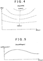
- the smoke limit fuel injection amount map QAFM is calculated based on the intake air amount GN per one revolution of the engine and the engine speed NE among the various data according to a smoke limit fuel injection amount map MapQAFM (S202).
- the smoke limit fuel injection amount QAFM is an upper limit value of the fuel injection amounts at which smoke is not generated in the exhaust gas even when combustion is performed in the gas taken in the combustion chamber 4.
- the tendency of the value is shown by a dashed contour. Note that the map shown in FIG. 4 is exemplary, and the map varies according to type of the engine.
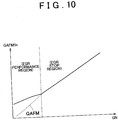
- an EGR smoke limit basic correction value QAFMegrbs is calculated according to an EGR smoke limit basic correction value map MapQAFMegrbs (S204).
- This EGR smoke limit basic correction value map MapQAFMegrbs is made by obtaining, through experiments, an increase amount by which the smoke limit fuel injection amount QAFM is increased due to the oxygen in the EGR gas under the condition that the EGR rate is 100 %, the atmospheric pressure Patm is 1013 hPa (i.e., 1 atmospheric pressure), the intake air temperature THA is 20 °C, and the coolant temperature THW is 80 °C.
- FIG. 5 shows this map.
- an EGR rate correction coefficient Kegr is calculated based on the EGR rate according to an EGR rate correction coefficient map MapEGR shown in FIG. 6 (S206).
- This EGR rate correction coefficient map MapEGR may be obtained through experiments. However, instead of using the map, the EGR rate may be used as it is.
- a target EGR rate obtained based on the engine load (in this case, the fuel injection amount) and the engine speed NE may be used as the EGR rate.
- the EGR rate may be obtained according to an EGR rate map which is made in advance through experiments based on the EGR gas pressure Pegr, the engine speed NE, and the controlled variable of the opening amount of the EGR valve 40.
- an atmospheric pressure correction coefficient Kpa is calculated based on the atmospheric pressure Patm according to an atmospheric pressure correction coefficient map MapPa shown in Fig. 7 (S208).
- the atmospheric correction coefficient map MapPa may be obtained through experiments so as to be used in order to calculate the atmospheric pressure correction coefficient Kpa.
- a ratio between the atmospheric pressure Patm and 1 atmospheric pressure may be calculated so as to be used in order to calculate the atmospheric pressure correction coefficient Kpa.
- an intake air temperature correction coefficient Ktha is calculated based on the intake air temperature THA according to an intake air temperature correction coefficient map MapTHA shown in FIG. 8 (S210).
- the intake air temperature correction coefficient map MapTHA may be obtained through experiments so as to be used. However, instead of using the map, a ratio between an intake air density at the intake air temperature THA and an intake air density at a reference temperature (in this case, 20 °C) may be used.
- a coolant temperature correction coefficient Kthw is calculated based on the coolant temperature THW according to a coolant temperature correction coefficient map MapTHW shown in FIG. 9 (S212).
- the coolant temperature correction coefficient map MapTHW may be obtained through experiments so as to be used. However, instead of using the map, a ratio between a gas density in the combustion chamber 4 at the coolant temperature THW and the gas density in the combustion chamber 4 at the reference temperature (in this case, 80°C) may be used.
- an EGR smoke limit correction value QAFMegr is calculated using the following equation (1) (S214). QAFMegr ⁇ QAFMegrbs ⁇ Kegr ⁇ Kpa ⁇ Ktha ⁇ Kthw
- the EGR smoke limit correction value QAFMegr shows an increase amount by which the smoke limit fuel injection amount QAFM is increased due to introduction of the EGR gas in the present operating state of the diesel engine 2.
- the final smoke limit fuel injection amount QAFMfin is calculated by increasing the smoke limit fuel injection amount QAFM by the EGR smoke limit correction value QAFMegr using the following equation (2).
- the increase correction is performed according to the EGR gas at each control cycle so as to calculate the final smoke limit fuel injection amount QAFMfin. Then, the final smoke limit fuel injection amount QAFMfin is used for a determination in step S104 and an upper limit value setting process in step S108 in the aforementioned fuel injection amount control process ( FIG. 2 ).
- the value of the smoke limit fuel injection amount QAFM is used in a region in which EGR is performed (hereinafter, referred to as "EGR performance region"), as shown by a dotted line.
- EGR performance region a region in which EGR is performed
- the limit of the fuel injection amounts at which smoke is not generated becomes larger. Therefore, a larger amount of fuel can be injected.
- the final smoke limit fuel injection amount QAFMfin calculation process ( FIG. 3 ) is equivalent to the process by the increasing means.
- the EGR smoke limit basic correction value QAFMegrbs is equivalent to the basic correction amount concerning the exhaust gas recirculation amount.
- the EGR smoke limit correction value QAFMegr is equivalent to the correction amount used for the increase correction of the smoke limit fuel injection amount.
- a diesel engine control system In a diesel engine control system according to a second embodiment, two combustion modes due to the EGR control, that is, a normal combustion mode and a low temperature combustion mode, are performed. Particularly when performing the low temperature combustion mode in which the EGR rate is extremely high, the increase correction of the smoke limit fuel injection amount QAFM is performed as in the first embodiment, whereby a rapid increase in the fuel injection amount is prevented from being limited at the time of acceleration.
- a fuel injection mode setting process shown in FIG. 12 is performed.
- a final smoke limit fuel injection amount QAFMfin calculation process shown in FIG. 16 is performed.
- a fuel injection amount control process shown in FIG. 17 is performed.
- An air-fuel ratio sensor which detects an air-fuel ratio AF based on components of exhaust gas, is provided in the exhaust gas system of the engine. A signal indicative of the air-fuel ratio AF is input to the ECU. Except for these, the configuration of the diesel engine control system according to the second embodiment is substantially the same as that of the diesel engine control system according to the first embodiment.
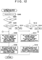
- the combustion mode setting process ( FIG. 12 ) will be described. The process is performed immediately before the final smoke limit fuel injection amount QAFMfin calculation process ( FIG. 16 ) and the fuel injection amount control process ( FIG. 17 ) at the same cycle as that of the processes in FIG. 16 and FIG. 17 .
- a first border determining value X and a second border determining value Y which are used for determining the combustion mode, are calculated based on a required engine load (in this case, an accelerator opening amount ACCP) (S300).
- these border determining values X, Y are set in a two-dimensional space using the engine speed NE and the required engine load (ACCP).
- the first border determining value X shown by the solid line is used for determining whether the combustion mode needs to be changed from the low temperature combustion mode to the normal combustion mode.
- the second border determining value Y shown by the dotted line is used for determining whether the combustion mode needs to be changed from the normal combustion mode to the low temperature combustion mode.
- Each of the border determining values X, Y is set in the ROM of the ECU in the form of a map or a computing equation in which the engine speed NE is used as a parameter.
- step S302 it is determined whether a low temperature combustion mode performance flag Ft is ON (S302). If the flag Ft is ON (i.e., YES in step S302), it is determined that the low temperature combustion mode is performed. Therefore, it is determined whether the required engine load (ACCP) is equal to or smaller than the first border determining value X (S304).
- the flag Ft is ON (i.e., YES in step S302), it is determined that the low temperature combustion mode is performed. Therefore, it is determined whether the required engine load (ACCP) is equal to or smaller than the first border determining value X (S304).
- a process for performing the low temperature combustion mode is performed. That is, a target throttle opening amount TAt is set according to a throttle opening amount map for the low temperature combustion mode (S306), and a target EGR valve opening amount EGRt is set according to an EGR valve opening amount map for the low temperature combustion mode (S308).
- the target throttle opening amount TAt and the target EGR valve opening amount EGRt are set such that the EGR rate becomes approximately 70 %, which is an extremely high EGR rate.
- the air-fuel ratio in the combustion chamber becomes slightly leaner than the stoichiometric air-fuel ratio.
- the target throttle opening amount TAt is achieved by controlling a motor for driving the throttle valve through feedback based on the throttle opening amount TA detected by the throttle opening amount sensor. Also, the feedback correction of the EGR valve opening amount is performed such that the EGR valve opening amount matches the target EGR valve opening amount EGRt, and accordingly the air-fuel ratio shown in FIG. 14 is achieved. Thus, an appropriate EGR valve opening amount is achieved.
- step S306 As long as the required engine load (ACCP) is equal to or smaller than the first border determining value X (i.e., YES in step S304), the process in step S306 and step S308 is continued, whereby the low temperature combustion is continued and the low temperature combustion mode performance flag Ft is maintained in the ON state.
- the required engine load (ACCP) is equal to or smaller than the first border determining value X (i.e., YES in step S304)
- the process in step S306 and step S308 is continued, whereby the low temperature combustion is continued and the low temperature combustion mode performance flag Ft is maintained in the ON state.
- the low temperature combustion mode performance flag Ft is turned OFF (S310). Accordingly, the combustion mode is changed from the low temperature combustion mode to the normal combustion mode. Subsequently, the process for performing the normal combustion is performed.
- the target throttle opening amount TAt is set according to the throttle opening amount map for the normal combustion mode (S312)
- the target EGR valve opening amount EGRt is set according to the EGR valve opening amount map for the normal combustion mode (S314).
- the target throttle opening amount TAt and the target EGR valve opening amount EGRt are set such that the EGR rate becomes equal to or smaller than 40 %, which is a relatively small EGR rate.
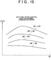
- the air-fuel ratio in the combustion chamber becomes by far leaner than the stoichiometric air-fuel ratio, as shown in FIG. 15 .
- the target throttle opening amount TAt is achieved in the same manner as in the case of the low temperature combustion mode. Also, the feedback correction of the EGR valve opening amount is performed such that the EGR valve opening amount matches the target EGR valve opening amount EGRt, and accordingly the air-fuel ratio shown in FIG. 15 is achieved. Thus, an appropriate EGR valve opening amount is achieved.
- the process for performing the normal combustion in the aforementioned steps S312 and S314 is continued. Then, as long as the required engine load is equal to or larger than the second border determining value Y (i.e., YES in step S316), the process in the steps S312 and S314 is continued, whereby the normal combustion is continued and the low temperature combustion mode performance flag Ft is maintained in the OFF state.
- the low temperature combustion mode performance flag Ft is turned ON (S318). Accordingly, the combustion mode is changed from the normal combustion mode to the low temperature combustion mode. Then, the aforementioned process for performing the low temperature combustion in steps S306 and S308 is performed. Thus, the combustion mode is set and is performed.
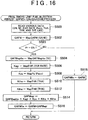
- steps S500, S502, and S504 to S516 are the same as steps S200 to S216 in FIG. 3 in the first embodiment.
- the smoke limit fuel injection amount QAFM is calculated (S502), it is determined whether the low temperature combustion mode performance flag Ft is ON (S503). If the flag Ft is ON (i.e., YES in step S503), the same process as in steps S204 to S216 in FIG. 3 is performed (S504 to S516). Thus, the final smoke limit fuel injection amount QAFMfin is calculated by performing the increase correction of the smoke limit fuel injection amount QAFM using the EGR smoke limit correction value QAFMegr. If the flag Ft is OFF (i.e., NO in step S503), the final smoke limit fuel injection amount QAFMfin is set to the smoke limit fuel injection amount QAFM (S518).
- the EGR smoke limit correction value QAFMegr is reflected in the final smoke limit fuel injection amount QAFMfin.
- the flag Ft is OFF, the EGR smoke limit correction value QAFMegr is not reflected in the final smoke limit fuel injection amount QAFMfin.
- the EGR smoke limit correction value QAFMegr becomes large, and the smoke limit fuel injection amount QAFM is greatly increased using the large EGR smoke limit correction value QAFMegr so as to obtain the final smoke limit fuel injection amount QAFMfin.
- the rate of the EGR gas is relatively small in the normal combustion mode, the smoke limit fuel injection amount QAFM is used without being corrected as the final smoke limit fuel injection amount QAFMfin.
- step S400 and steps S404 to S410 are the same as step S100, and steps S104 to S110 in FIG. 2 .
- the low temperature combustion mode performance flag Ft is ON (S401). If the flag Ft is ON (i.e., YES in step S401), the basic required injection amount Q for the low temperature combustion mode is calculated. If the flag Ft is OFF (i.e., NO in step S401), the basic required injection amount Q for the normal combustion mode is calculated (S402).
- the basic required injection amount Q for the low temperature combustion mode is set based on the accelerator opening amount ACCP considering pumping loss, acceleration performance, and the like in the low temperature combustion mode.
- the basic required injection amount Q for the normal combustion mode is set based on the accelerator opening amount ACCP considering pumping loss, acceleration performance, and the like in the normal combustion mode.
- the final fuel injection amount QFINC is set using the present final smoke limit fuel injection amount QAFMfin as the upper limit in the same manner as in the aforementioned steps S104 to S110 in FIG. 2 (S404 to S408).
- the injection period Tq corresponding to the final fuel injection amount QFINC is calculated (S410), and then the fuel is injected.
- the value of the smoke limit fuel injection amount QAFM shown by a dotted line is used particularly in the low temperature combustion region in the EGR performance region.
- the final smoke limit fuel injection amount QAFMfin shown by a solid line is used. Therefore, the limit of the fuel injection amounts at which smoke is not generated becomes much larger. Thus, a larger amount of fuel can be injected.
- the final smoke limit fuel injection amount QAFMfin calculation process ( FIG. 16 ) is equivalent to the process by the increasing means.
- the feedback correction control which is performed for the EGR valve opening amount such that the EGR valve opening amount matches the target EGR valve opening amount EGRt, and accordingly the air-fuel ratio shown in FIG. 14 and FIG. 15 is achieved, is equivalent to the second feedback means.
- the final smoke limit fuel injection amount QAFMfin is obtained by increasing the smoke limit fuel injection amount QAFM by the EGR smoke limit correction value QAFMegr that is determined considering the residual oxygen amount in the EGR gas, the final smoke limit fuel injection amount QAFMfin is greatly increased according to the EGR gas amount.
- a diesel engine control system according to a third embodiment of the invention is different from the diesel engine control system according to the first embodiment or the second embodiment in the method of calculating the final smoke limit fuel injection amount QAFMfin. Except for this calculation method, the diesel engine control system according to the third embodiment of the invention is the same as the diesel engine control system according to the first embodiment or the second embodiment n.
- FIG. 19 shows part of the final smoke limit fuel injection amount QAFMfin calculation process. When this process is applied to the first embodiment, this process is performed instead of the process in steps S204 to S216 in FIG. 3 . When this process is applied to the second embodiment, this process is performed instead of the process in steps S504 to S516 in FIG. 16 . Other configurations are the same as those in the first embodiment or the second embodiment.
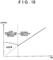
- a basic EGR smoke limit value QAFMminbs is calculated based on the engine speed NE according to a basic EGR smoke limit value map MapQAFMminbs (S604).
- the basic EGR smoke limit value QAFMminbs is the smoke limit fuel injection amount, which is obtained through experiments based on the oxygen in the intake air amount GN per one revolution of the engine under the condition that the EGR rate is 0 %, the atmospheric pressure Patm is 1013 hPa the intake air temperature THA is 20 °C, and the coolant temperature THW is 80 °C.
- a map of the basic EGR smoke limit value QAFMminbs is made as shown in FIG. 20 .
- an EGR rate correction coefficient Kminegr is calculated based on the EGR rate according to an EGR rate correction coefficient map MapminEGR shown in FIG. 21 (S606).
- This EGR rate correction coefficient Kminegr is a correction coefficient for obtaining a total oxygen amount in the intake air and the EGR gas when the EGR gas is added to the intake air.
- the EGR rate correction coefficient map MapminEGR is obtained through experiments.
- the atmospheric pressure correction coefficient Kpa is calculated based on the atmospheric pressure Patm according to the atmospheric pressure correction coefficient map MapPa shown in FIG. 7 in the first embodiment (S608).
- the intake air temperature correction coefficient Ktha is calculated based on the intake air temperature THA according to the intake air temperature correction coefficient map MapTHA shown in FIG. 8 in the first embodiment (S610).
- the coolant temperature correction coefficient Kthw is calculated based on the coolant temperature THW according to the coolant temperature correction coefficient map MapTHW shown in FIG. 9 in the first embodiment (S612).
- the methods of calculating the correction coefficients without using the maps in steps S608 to S612 are the same as in steps S208 to S212 in the first embodiment.
- the EGR smoke limit value QAFMmin is calculated using the following equation (3). QAFMmin ⁇ QAFMminbs ⁇ Kminegr ⁇ Kpa ⁇ Ktha ⁇ Kthw
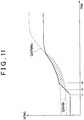
- This EGR smoke limit value QAFMmin is equivalent to the entire amount of the smoke limit fuel injection amount when the EGR gas is introduced in the present operating state of the diesel engine 2. Accordingly, as shown in the following equation (4), the final smoke limit fuel injection amount QAFMfin is set to the larger value of the smoke limit fuel injection amount QAFM and the EGR smoke limit value QAFMmin (S616).
- QAFMfin ⁇ MAX QAFM , QAFMmin MAX [ ] indicates an operator which extracts the largest value among the values in the brackets.
- the final smoke limit fuel injection amount QAFMfin that is thus calculated is used in the determination in step S104 or S404 and the upper limit value setting process in step S108 or S408 in the aforementioned fuel injection amount control process ( FIG. 2 or FIG. 17 ).
- the final smoke limit fuel injection amount QAFMfin when the smoke limit fuel injection amount QAFM (shown by a dotted line) is smaller than the EGR smoke limit value QAFMmin (shown by a dashed line) in the EGR performance region, the final smoke limit fuel injection amount QAFMfin is set to the EGR smoke limit value QAFMmin.
- the final smoke limit fuel injection amount QAFMfin shown by a solid line is used in the EGR performance region, the limit of the fuel injection amounts at which smoke is not generated becomes larger. Therefore, a larger amount of fuel can be injected.
- the final smoke limit fuel injection amount QAFMfin calculation process in FIG. 19 for obtaining the final smoke limit fuel injection amount QAFMfin (which is applied to the process shown in FIG. 3 or FIG. 16 ) is equivalent to the process by the limiting means.
- the basic EGR smoke limit value map MapQAFMminbs is equivalent to the EGR base smoke limit fuel injection amount
- the EGR smoke limit value QAFMmin is equivalent to the EGR smoke limit fuel injection amount.
- a diesel engine control system according to a fourth embodiment is different from the diesel engine control system according to the first embodiment in the method of calculating the final smoke limit fuel injection amount QAFMfin. That is, a process shown in FIG. 23 is performed instead of the final smoke limit fuel injection amount QAFMfin calculation process (in FIG. 3 ) in the first embodiment. Except for this calculation method, the diesel engine control system according to the fourth embodiment is the same as the diesel engine control system according to the first embodiment.
- the final smoke limit fuel injection amount QAFMfin calculation process (in FIG. 23 ) will be described.
- detection results from the various sensors and various data which are calculated based on the detection results (an intake air amount GN, the engine speed NE, the EGR rate, the atmospheric pressure Patm, the intake air temperature THA, the coolant temperature THW, and the like) are read in a working area of the RAM (S700).
- an EGR gas amount Gegr (g) is calculated using the following equation (5) based on the intake air amount GN per one revolution of the engine and the EGR rate which is calculated in the same manner as in the first embodiment (S702).
- the value of the air-fuel ratio ⁇ is 1 when the air-fuel ratio is equal to the stoichiometric air-fuel ratio.
- the air-fuel ratio ⁇ increases in proportion to an increase in the oxygen concentration.
- the air-fuel ratio ⁇ may be measured by a ⁇ sensor provided in the exhaust system.
- the air-fuel ratio ⁇ is calculated using the following equation (7). ⁇ ⁇ GA / Gf ⁇ 14.7
- Gf signifies a fuel amount (g) per unit time during which fuel is injected into the combustion chamber, which is obtained from a fuel injection amount command value.
- GA signifies an intake air amount (g) per unit time.
- GNfin ⁇ GN + GNegr
- the final smoke limit fuel injection amount QAFMfin is calculated based on the final intake air amount GNfin and the engine speed NE according to the smoke limit fuel injection amount map MapQAFM (S708).
- the smoke limit fuel injection amount map MapQAFM used in the fourth embodiment is the same as the map shown in FIG. 4 in the first embodiment. In FIG. 4 , the smoke limit fuel injection amount QAFM is obtained. However, in the fourth embodiment of the invention, the value of the smoke limit fuel injection amount QAFM in FIG. 4 is obtained as the final smoke limit fuel injection amount QAFMfin.
- the final smoke limit fuel injection amount QAFMfin thus calculated is used in the determination in step S104 and the upper limit value setting process in step S108 in the fuel injection amount control process ( FIG. 2 ).
- the upper limit of the fuel injection amount at which smoke is not generated becomes larger in the EGR performance region, and a larger amount of fuel can be injected.
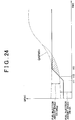
- the final fuel injection amount QFINC can be increased to sufficiently correspond to the acceleration operation until time t13, as compared with the case where the fuel injection amount is limited at time t12 by the smoke limit fuel injection amount (shown by a dotted line) that is set based on only the intake air amount GN.
- the fuel injection amount can be increased without generating smoke, and higher acceleration performance can be obtained, as compared with the case where the fuel injection amount shown by hatching is limited by the smoke limit fuel injection amount QAFM (shown by the dotted line). Particularly when acceleration is performed after idling or deceleration, a remarkable effect can be obtained since the intake air amount is small.
- the acceleration performance can be improved without decreasing the EGR gas amount while suppressing generation of smoke.
- a diesel engine control system is different from the diesel engine control system according to the second embodiment in the method of calculating the final smoke limit fuel injection amount QAFMfin. That is, the final smoke limit fuel injection amount QAFMfin calculation process shown in FIG. 25 is performed instead of the final smoke limit fuel injection amount QAFMfin calculation process ( FIG. 16 ) in the second embodiment. Except for this calculation method, the diesel engine control system according to the fifth embodiment is the same as the diesel engine control system according to the second embodiment.
- steps S800 and S802 to S808 are the same as steps S700 to S708 in the final smoke limit fuel injection amount QAFMfin calculation process ( FIG. 23 ) in the fourth embodiment.
- the process shown in FIG. 25 is different from the process shown in FIG. 23 in that the determination as to whether the low temperature combustion mode performance flag Ft is ON is made (S801) subsequently to step S800, and in that a process of setting the final smoke limit fuel injection amount QAFMfin is performed according to the same map as the map shown in FIG. 4 (S810) if the flag Ft is OFF.
- the final intake air amount GNfin is calculated by adding the converted value GNegr based on oxygen in the EGR gas to the intake air amount GN gas at the time of low temperature combustion when the EGR rate is particularly high (S802 to S806).
- the final smoke limit fuel injection amount QAFMfin is increased (S808).
- an EGR smoke limit correction value (QAFMegr) is calculated considering an oxygen amount in EGR gas (S200 to S214), and a final smoke limit fuel injection amount (QAFMfin) is set by increasing the smoke limit fuel injection amount (QAFM) by the EGR smoke limit correction value (QAFMegr) (S216).
Landscapes
- Engineering & Computer Science (AREA)
- Chemical & Material Sciences (AREA)
- Combustion & Propulsion (AREA)
- Mechanical Engineering (AREA)
- General Engineering & Computer Science (AREA)
- Output Control And Ontrol Of Special Type Engine (AREA)
- Electrical Control Of Air Or Fuel Supplied To Internal-Combustion Engine (AREA)
- Exhaust-Gas Circulating Devices (AREA)
- Combined Controls Of Internal Combustion Engines (AREA)
Claims (6)
- Kraftstoffeinspritzmengensteuerungsvorrichtung für eine Brennkraftmaschine (2), die eine Abgasrückführung durchführt, und zum Beschränken einer für die Brennkraftmaschine (2) erforderlichen Kraftstoffeinspritzmenge (Q) angeordnet ist, auf der Grundlage einer Rauchbeschränkungskraftstoffeinspritzmenge (QAFM), die gemäß einer Einlassluftmenge festgelegt wird, um eine Rauchentwicklung zu unterdrücken, mit:einer Beschränkungseinrichtung zum Berechnen einer EGR-Rauchbeschränkungskraftstoffeinspritzmenge (QAFMmin), wodurch sowohl eine Einlassluftmenge als auch eine Abgasrückführungsmenge einschließlich eines Restsauerstoffs berücksichtigt werden kann, auf der Grundlage eines Betriebszustands der Brennkraftmaschine (2),dadurch gekennzeichnet, dass die Beschränkungseinrichtungeine EGR-Basisrauchbeschränkungskraftstoffeinspritzmenge (QAFMminbs) gemäß einer Drehzahl (NE) der Brennkraftmaschine (2) berechnet und die EGR-Rauchbeschränkungskraftstoffeinspritzmenge (QAFMmin) auf der Grundlage der EGR-Basisrauchbeschränkungskraftstoffeinspritzmenge (QAFMminbs), einer Abgasrückführungsrate, eines Umgebungsdrucks und eines Temperaturfaktors erlangt, unddie für die Brennkraftmaschine (2) erforderliche Kraftstoffeinspritzmenge (Q) auf der Grundlage des größeren Werts von der EGR-Rauchbeschränkungskraftstoffeinspritzmenge (QAFMmin) und der Rauchbeschränkungskraftstoffeinspritzmenge (QAFM) beschränkt.
- Kraftstoffeinspritzmengensteuerungsvorrichtung gemäß Anspruch 1, wobei der Temperaturfaktor mindestens einer von der Einlasslufttemperatur (TH1) und der Kühlmitteltemperatur (THW) der Brennkraftmaschine (2) ist.
- Kraftstoffeinspritzmengensteuerungsvorrichtung gemäß Anspruch 1 oder 2, des Weiteren mit:
einer ersten Regeleinrichtung zum Festlegen einer Soll-Einlassluftmenge auf der Grundlage des Betriebszustands der Brennkraftmaschine (2) und Einstellen der Abgasrückführungsmenge, sodass eine tatsächliche Einlassluftmenge mit der Soll-Einlassluftmenge übereinstimmt. - Kraftstoffeinspritzmengensteuerungsvorrichtung gemäß Anspruch 1 oder 2, des Weiteren mit:
einer zweiten Regeleinrichtung zum Festlegen eines Soll-Luft-Kraftstoff-Verhältnisses auf der Grundlage des Betriebszustands der Brennkraftmaschine (2) und Einstellen der Abgasrückführungsmenge, sodass ein tatsächliches Abgas-Luft-Kraftstoff-Verhältnis mit dem Soll-Luft-Kraftstoff-Verhältnis übereinstimmt. - Kraftstoffeinspritzmengensteuerungsvorrichtung gemäß einem der Ansprüche 1, 2 und 4, wobei die Abgasrückführung in einem Niedertemperaturverbrennungsmodus durchgeführt wird, bei dem eine Rauchentwicklung dadurch unterdrückt wird, dass die Abgasrückführungsmenge äußerst großgemacht wird.
- Kraftstoffeinspritzmengensteuerungsvorrichtung gemäß einem der Ansprüche 1 bis 5, wobei die Abgasrückführungsbrennkraftmaschine ein Abgasrückführungsdieselmotor (2) ist.
Applications Claiming Priority (2)
| Application Number | Priority Date | Filing Date | Title |
|---|---|---|---|
| JP2003071986A JP4135539B2 (ja) | 2003-03-17 | 2003-03-17 | 排気再循環式内燃機関の燃料噴射量制御装置 |
| EP04006139.2A EP1460251B1 (de) | 2003-03-17 | 2004-03-15 | Einrichtung und Verfahren zur Steuerung der Einspritzmenge für eine Brennkraftmaschine mit Abgasrückführung |
Related Parent Applications (3)
| Application Number | Title | Priority Date | Filing Date |
|---|---|---|---|
| EP04006139.2A Division EP1460251B1 (de) | 2003-03-17 | 2004-03-15 | Einrichtung und Verfahren zur Steuerung der Einspritzmenge für eine Brennkraftmaschine mit Abgasrückführung |
| EP04006139.2A Division-Into EP1460251B1 (de) | 2003-03-17 | 2004-03-15 | Einrichtung und Verfahren zur Steuerung der Einspritzmenge für eine Brennkraftmaschine mit Abgasrückführung |
| EP04006139.2 Division | 2004-03-15 |
Publications (2)
| Publication Number | Publication Date |
|---|---|
| EP2292912A1 EP2292912A1 (de) | 2011-03-09 |
| EP2292912B1 true EP2292912B1 (de) | 2019-10-23 |
Family
ID=32821289
Family Applications (2)
| Application Number | Title | Priority Date | Filing Date |
|---|---|---|---|
| EP04006139.2A Expired - Lifetime EP1460251B1 (de) | 2003-03-17 | 2004-03-15 | Einrichtung und Verfahren zur Steuerung der Einspritzmenge für eine Brennkraftmaschine mit Abgasrückführung |
| EP10189425.1A Expired - Lifetime EP2292912B1 (de) | 2003-03-17 | 2004-03-15 | Vorrichtung zur Steuerung der Einspritzmenge für eine Brennkraftmaschine mit Abgasrückführung |
Family Applications Before (1)
| Application Number | Title | Priority Date | Filing Date |
|---|---|---|---|
| EP04006139.2A Expired - Lifetime EP1460251B1 (de) | 2003-03-17 | 2004-03-15 | Einrichtung und Verfahren zur Steuerung der Einspritzmenge für eine Brennkraftmaschine mit Abgasrückführung |
Country Status (2)
| Country | Link |
|---|---|
| EP (2) | EP1460251B1 (de) |
| JP (1) | JP4135539B2 (de) |
Families Citing this family (15)
| Publication number | Priority date | Publication date | Assignee | Title |
|---|---|---|---|---|
| JP4135539B2 (ja) | 2003-03-17 | 2008-08-20 | トヨタ自動車株式会社 | 排気再循環式内燃機関の燃料噴射量制御装置 |
| US6886545B1 (en) * | 2004-03-05 | 2005-05-03 | Haldex Hydraulics Ab | Control scheme for exhaust gas circulation system |
| JP4049158B2 (ja) | 2005-03-09 | 2008-02-20 | トヨタ自動車株式会社 | 内燃機関の燃料噴射制御装置 |
| JP2006299833A (ja) * | 2005-04-15 | 2006-11-02 | Toyota Industries Corp | ディーゼルエンジンにおける燃料噴射量制御装置 |
| US7063076B1 (en) * | 2005-05-16 | 2006-06-20 | Detroit Diesel Corporation | Method of smoke limiting engine |
| JP2008196377A (ja) | 2007-02-13 | 2008-08-28 | Toyota Motor Corp | 内燃機関の制御装置 |
| JP4946904B2 (ja) * | 2008-02-12 | 2012-06-06 | トヨタ自動車株式会社 | 内燃機関の制御システム |
| FR2946392B1 (fr) * | 2009-06-04 | 2015-11-13 | Peugeot Citroen Automobiles Sa | Procede et dispositif de controle moteur, vehicule equipe de ce dispositif, support d'enregistrement |
| JP4997272B2 (ja) | 2009-09-01 | 2012-08-08 | 本田技研工業株式会社 | 内燃機関の燃料供給制御装置 |
| FR2985781B1 (fr) * | 2012-01-13 | 2015-12-18 | Renault Sas | Controle d'un moteur a combustion interne muni d'un circuit de recirculation partielle de gaz d'echappement |
| SE538206C2 (sv) * | 2012-07-05 | 2016-04-05 | Scania Cv Ab | Förfarande och system vid framförande av fordon, där luft/bränsleförhållandet styrs |
| US20140174406A1 (en) * | 2012-12-20 | 2014-06-26 | Caterpillar, Inc. | Control system for an engine with egr flow |
| DE102014214431A1 (de) * | 2014-07-23 | 2016-01-28 | Robert Bosch Gmbh | Verfahren und Vorrichtung zum Ermitteln einer Sollbetriebsgröße einer Brenn-kraftmaschine |
| US9903289B2 (en) * | 2014-09-08 | 2018-02-27 | General Electric Company | Method and systems for EGR control |
| GB2579345B (en) | 2018-11-09 | 2020-12-16 | Perkins Engines Co Ltd | Method for operating an internal combustion engine in a transition operating mode |
Family Cites Families (8)
| Publication number | Priority date | Publication date | Assignee | Title |
|---|---|---|---|---|
| JPS5612027A (en) * | 1979-07-10 | 1981-02-05 | Nippon Denso Co Ltd | Electric controller for injection pump |
| JP2599953B2 (ja) | 1988-02-26 | 1997-04-16 | マツダ株式会社 | ディーゼルエンジンの燃焼制御装置 |
| JPH09195825A (ja) * | 1996-01-18 | 1997-07-29 | Toyota Motor Corp | ディーゼル機関の制御装置 |
| EP0962638B1 (de) * | 1998-06-05 | 2006-01-11 | Toyota Jidosha Kabushiki Kaisha | Verbrennungsmotor |
| JP3551768B2 (ja) | 1998-06-22 | 2004-08-11 | トヨタ自動車株式会社 | 内燃機関 |
| JP3225957B2 (ja) * | 1999-02-02 | 2001-11-05 | トヨタ自動車株式会社 | 内燃機関 |
| JP3864671B2 (ja) * | 2000-06-12 | 2007-01-10 | 日産自動車株式会社 | ディーゼルエンジンの燃料噴射制御装置 |
| JP4135539B2 (ja) | 2003-03-17 | 2008-08-20 | トヨタ自動車株式会社 | 排気再循環式内燃機関の燃料噴射量制御装置 |
-
2003
- 2003-03-17 JP JP2003071986A patent/JP4135539B2/ja not_active Expired - Lifetime
-
2004
- 2004-03-15 EP EP04006139.2A patent/EP1460251B1/de not_active Expired - Lifetime
- 2004-03-15 EP EP10189425.1A patent/EP2292912B1/de not_active Expired - Lifetime
Non-Patent Citations (1)
| Title |
|---|
| None * |
Also Published As
| Publication number | Publication date |
|---|---|
| EP1460251A3 (de) | 2010-02-24 |
| JP2004278431A (ja) | 2004-10-07 |
| JP4135539B2 (ja) | 2008-08-20 |
| EP2292912A1 (de) | 2011-03-09 |
| EP1460251B1 (de) | 2019-07-24 |
| EP1460251A2 (de) | 2004-09-22 |
Similar Documents
| Publication | Publication Date | Title |
|---|---|---|
| US5704340A (en) | Excess air rate detecting apparatus and an excess air rate control apparatus for an engine | |
| EP2292912B1 (de) | Vorrichtung zur Steuerung der Einspritzmenge für eine Brennkraftmaschine mit Abgasrückführung | |
| EP1862657B1 (de) | Kraftstoffeinspritzsteuereinheit für brennkraftmotor | |
| EP1548255B1 (de) | Steuervorrichtung für eine Brennkraftmaschine | |
| JP6141746B2 (ja) | 内燃機関の制御装置 | |
| EP1312784A1 (de) | Verfahren und System zur Regelung einer Brennkraftmaschine | |
| EP1591650A2 (de) | Vorrichtung und Methode zur Steuerung der Kraftstoffeinspritzung in einer Brennkraftmaschine | |
| US7360525B2 (en) | Control system for internal combustion engine | |
| US20110295525A1 (en) | Cylinder intake air amount calculating apparatus for internal combustion engine | |
| US7258106B2 (en) | Control system for internal combustion engine | |
| EP2211044B1 (de) | AGR-Steuerung und AGR-Steuerverfahren für Verbrennungsmotoren | |
| US20010035151A1 (en) | Controlling apparatus and method of internal combustion engine | |
| JP4479810B2 (ja) | 排気再循環式内燃機関の燃料噴射量制御装置 | |
| EP1781921B1 (de) | Verbrennungsmotor | |
| JPWO1998026169A1 (ja) | 内燃機関の燃焼制御装置 | |
| JP5111534B2 (ja) | 内燃機関のegr制御装置 | |
| US8229654B2 (en) | Device for limiting output of internal combustion engine when the engine has abnormality | |
| JP7433328B2 (ja) | Egr制御方法及びegr制御装置 | |
| EP2390490B1 (de) | Steuerungsvorrichtung für einen verbrennungsmotor | |
| JPH1136926A (ja) | 筒内噴射式エンジン | |
| US8909458B2 (en) | EGR controller for internal combustion engine | |
| JP3743078B2 (ja) | 筒内噴射式内燃機関 | |
| JP2002317684A (ja) | 内燃機関の運転状態判別装置 | |
| JP3562137B2 (ja) | 内燃機関の制御装置 | |
| JP2623941B2 (ja) | 内燃機関の燃料制御装置 |
Legal Events
| Date | Code | Title | Description |
|---|---|---|---|
| PUAI | Public reference made under article 153(3) epc to a published international application that has entered the european phase |
Free format text: ORIGINAL CODE: 0009012 |
|
| 17P | Request for examination filed |
Effective date: 20101029 |
|
| AC | Divisional application: reference to earlier application |
Ref document number: 1460251 Country of ref document: EP Kind code of ref document: P |
|
| AK | Designated contracting states |
Kind code of ref document: A1 Designated state(s): AT BE BG CH CY CZ DE DK EE ES FI FR GB GR HU IE IT LI LU MC NL PL PT RO SE SI SK TR |
|
| AX | Request for extension of the european patent |
Extension state: AL LT LV MK |
|
| RAP1 | Party data changed (applicant data changed or rights of an application transferred) |
Owner name: TOYOTA JIDOSHA KABUSHIKI KAISHA |
|
| STAA | Information on the status of an ep patent application or granted ep patent |
Free format text: STATUS: EXAMINATION IS IN PROGRESS |
|
| 17Q | First examination report despatched |
Effective date: 20170518 |
|
| RIC1 | Information provided on ipc code assigned before grant |
Ipc: F02D 41/18 20060101ALI20190321BHEP Ipc: F02D 21/08 20060101AFI20190321BHEP Ipc: F02D 35/00 20060101ALI20190321BHEP Ipc: F02D 41/00 20060101ALI20190321BHEP |
|
| GRAP | Despatch of communication of intention to grant a patent |
Free format text: ORIGINAL CODE: EPIDOSNIGR1 |
|
| STAA | Information on the status of an ep patent application or granted ep patent |
Free format text: STATUS: GRANT OF PATENT IS INTENDED |
|
| INTG | Intention to grant announced |
Effective date: 20190503 |
|
| RIN1 | Information on inventor provided before grant (corrected) |
Inventor name: KIBE, KAZUYA Inventor name: NEGISHI, AKIYOSHI |
|
| GRAS | Grant fee paid |
Free format text: ORIGINAL CODE: EPIDOSNIGR3 |
|
| GRAA | (expected) grant |
Free format text: ORIGINAL CODE: 0009210 |
|
| STAA | Information on the status of an ep patent application or granted ep patent |
Free format text: STATUS: THE PATENT HAS BEEN GRANTED |
|
| AC | Divisional application: reference to earlier application |
Ref document number: 1460251 Country of ref document: EP Kind code of ref document: P |
|
| AK | Designated contracting states |
Kind code of ref document: B1 Designated state(s): AT BE BG CH CY CZ DE DK EE ES FI FR GB GR HU IE IT LI LU MC NL PL PT RO SE SI SK TR |
|
| REG | Reference to a national code |
Ref country code: GB Ref legal event code: FG4D |
|
| REG | Reference to a national code |
Ref country code: CH Ref legal event code: EP |
|
| REG | Reference to a national code |
Ref country code: IE Ref legal event code: FG4D |
|
| REG | Reference to a national code |
Ref country code: DE Ref legal event code: R096 Ref document number: 602004054322 Country of ref document: DE |
|
| REG | Reference to a national code |
Ref country code: AT Ref legal event code: REF Ref document number: 1193887 Country of ref document: AT Kind code of ref document: T Effective date: 20191115 |
|
| REG | Reference to a national code |
Ref country code: NL Ref legal event code: MP Effective date: 20191023 |
|
| REG | Reference to a national code |
Ref country code: DE Ref legal event code: R084 Ref document number: 602004054322 Country of ref document: DE |
|
| PG25 | Lapsed in a contracting state [announced via postgrant information from national office to epo] |
Ref country code: PL Free format text: LAPSE BECAUSE OF FAILURE TO SUBMIT A TRANSLATION OF THE DESCRIPTION OR TO PAY THE FEE WITHIN THE PRESCRIBED TIME-LIMIT Effective date: 20191023 Ref country code: NL Free format text: LAPSE BECAUSE OF FAILURE TO SUBMIT A TRANSLATION OF THE DESCRIPTION OR TO PAY THE FEE WITHIN THE PRESCRIBED TIME-LIMIT Effective date: 20191023 Ref country code: ES Free format text: LAPSE BECAUSE OF FAILURE TO SUBMIT A TRANSLATION OF THE DESCRIPTION OR TO PAY THE FEE WITHIN THE PRESCRIBED TIME-LIMIT Effective date: 20191023 Ref country code: PT Free format text: LAPSE BECAUSE OF FAILURE TO SUBMIT A TRANSLATION OF THE DESCRIPTION OR TO PAY THE FEE WITHIN THE PRESCRIBED TIME-LIMIT Effective date: 20200224 Ref country code: FI Free format text: LAPSE BECAUSE OF FAILURE TO SUBMIT A TRANSLATION OF THE DESCRIPTION OR TO PAY THE FEE WITHIN THE PRESCRIBED TIME-LIMIT Effective date: 20191023 Ref country code: BG Free format text: LAPSE BECAUSE OF FAILURE TO SUBMIT A TRANSLATION OF THE DESCRIPTION OR TO PAY THE FEE WITHIN THE PRESCRIBED TIME-LIMIT Effective date: 20200123 Ref country code: GR Free format text: LAPSE BECAUSE OF FAILURE TO SUBMIT A TRANSLATION OF THE DESCRIPTION OR TO PAY THE FEE WITHIN THE PRESCRIBED TIME-LIMIT Effective date: 20200124 Ref country code: SE Free format text: LAPSE BECAUSE OF FAILURE TO SUBMIT A TRANSLATION OF THE DESCRIPTION OR TO PAY THE FEE WITHIN THE PRESCRIBED TIME-LIMIT Effective date: 20191023 |
|
| REG | Reference to a national code |
Ref country code: DE Ref legal event code: R097 Ref document number: 602004054322 Country of ref document: DE |
|
| PG25 | Lapsed in a contracting state [announced via postgrant information from national office to epo] |
Ref country code: CZ Free format text: LAPSE BECAUSE OF FAILURE TO SUBMIT A TRANSLATION OF THE DESCRIPTION OR TO PAY THE FEE WITHIN THE PRESCRIBED TIME-LIMIT Effective date: 20191023 Ref country code: RO Free format text: LAPSE BECAUSE OF FAILURE TO SUBMIT A TRANSLATION OF THE DESCRIPTION OR TO PAY THE FEE WITHIN THE PRESCRIBED TIME-LIMIT Effective date: 20191023 Ref country code: EE Free format text: LAPSE BECAUSE OF FAILURE TO SUBMIT A TRANSLATION OF THE DESCRIPTION OR TO PAY THE FEE WITHIN THE PRESCRIBED TIME-LIMIT Effective date: 20191023 Ref country code: DK Free format text: LAPSE BECAUSE OF FAILURE TO SUBMIT A TRANSLATION OF THE DESCRIPTION OR TO PAY THE FEE WITHIN THE PRESCRIBED TIME-LIMIT Effective date: 20191023 |
|
| REG | Reference to a national code |
Ref country code: AT Ref legal event code: MK05 Ref document number: 1193887 Country of ref document: AT Kind code of ref document: T Effective date: 20191023 |
|
| PLBE | No opposition filed within time limit |
Free format text: ORIGINAL CODE: 0009261 |
|
| STAA | Information on the status of an ep patent application or granted ep patent |
Free format text: STATUS: NO OPPOSITION FILED WITHIN TIME LIMIT |
|
| PG25 | Lapsed in a contracting state [announced via postgrant information from national office to epo] |
Ref country code: SK Free format text: LAPSE BECAUSE OF FAILURE TO SUBMIT A TRANSLATION OF THE DESCRIPTION OR TO PAY THE FEE WITHIN THE PRESCRIBED TIME-LIMIT Effective date: 20191023 Ref country code: IT Free format text: LAPSE BECAUSE OF FAILURE TO SUBMIT A TRANSLATION OF THE DESCRIPTION OR TO PAY THE FEE WITHIN THE PRESCRIBED TIME-LIMIT Effective date: 20191023 |
|
| 26N | No opposition filed |
Effective date: 20200724 |
|
| PG25 | Lapsed in a contracting state [announced via postgrant information from national office to epo] |
Ref country code: MC Free format text: LAPSE BECAUSE OF FAILURE TO SUBMIT A TRANSLATION OF THE DESCRIPTION OR TO PAY THE FEE WITHIN THE PRESCRIBED TIME-LIMIT Effective date: 20191023 |
|
| REG | Reference to a national code |
Ref country code: CH Ref legal event code: PL |
|
| PG25 | Lapsed in a contracting state [announced via postgrant information from national office to epo] |
Ref country code: AT Free format text: LAPSE BECAUSE OF FAILURE TO SUBMIT A TRANSLATION OF THE DESCRIPTION OR TO PAY THE FEE WITHIN THE PRESCRIBED TIME-LIMIT Effective date: 20191023 Ref country code: SI Free format text: LAPSE BECAUSE OF FAILURE TO SUBMIT A TRANSLATION OF THE DESCRIPTION OR TO PAY THE FEE WITHIN THE PRESCRIBED TIME-LIMIT Effective date: 20191023 |
|
| REG | Reference to a national code |
Ref country code: BE Ref legal event code: MM Effective date: 20200331 |
|
| PG25 | Lapsed in a contracting state [announced via postgrant information from national office to epo] |
Ref country code: LU Free format text: LAPSE BECAUSE OF NON-PAYMENT OF DUE FEES Effective date: 20200315 |
|
| PG25 | Lapsed in a contracting state [announced via postgrant information from national office to epo] |
Ref country code: LI Free format text: LAPSE BECAUSE OF NON-PAYMENT OF DUE FEES Effective date: 20200331 Ref country code: CH Free format text: LAPSE BECAUSE OF NON-PAYMENT OF DUE FEES Effective date: 20200331 Ref country code: FR Free format text: LAPSE BECAUSE OF NON-PAYMENT OF DUE FEES Effective date: 20200331 Ref country code: IE Free format text: LAPSE BECAUSE OF NON-PAYMENT OF DUE FEES Effective date: 20200315 |
|
| PG25 | Lapsed in a contracting state [announced via postgrant information from national office to epo] |
Ref country code: BE Free format text: LAPSE BECAUSE OF NON-PAYMENT OF DUE FEES Effective date: 20200331 |
|
| GBPC | Gb: european patent ceased through non-payment of renewal fee |
Effective date: 20200315 |
|
| PG25 | Lapsed in a contracting state [announced via postgrant information from national office to epo] |
Ref country code: GB Free format text: LAPSE BECAUSE OF NON-PAYMENT OF DUE FEES Effective date: 20200315 |
|
| PG25 | Lapsed in a contracting state [announced via postgrant information from national office to epo] |
Ref country code: TR Free format text: LAPSE BECAUSE OF FAILURE TO SUBMIT A TRANSLATION OF THE DESCRIPTION OR TO PAY THE FEE WITHIN THE PRESCRIBED TIME-LIMIT Effective date: 20191023 Ref country code: CY Free format text: LAPSE BECAUSE OF FAILURE TO SUBMIT A TRANSLATION OF THE DESCRIPTION OR TO PAY THE FEE WITHIN THE PRESCRIBED TIME-LIMIT Effective date: 20191023 |
|
| PGFP | Annual fee paid to national office [announced via postgrant information from national office to epo] |
Ref country code: DE Payment date: 20230131 Year of fee payment: 20 |
|
| P01 | Opt-out of the competence of the unified patent court (upc) registered |
Effective date: 20230427 |
|
| REG | Reference to a national code |
Ref country code: DE Ref legal event code: R071 Ref document number: 602004054322 Country of ref document: DE |