EP2292930A2 - Procédés et systèmes visant à utiliser le surplus d'énergie généré par les systèmes de production d'énergie renouvelable pour traiter les déchets organiques - Google Patents
Procédés et systèmes visant à utiliser le surplus d'énergie généré par les systèmes de production d'énergie renouvelable pour traiter les déchets organiques Download PDFInfo
- Publication number
- EP2292930A2 EP2292930A2 EP10168659A EP10168659A EP2292930A2 EP 2292930 A2 EP2292930 A2 EP 2292930A2 EP 10168659 A EP10168659 A EP 10168659A EP 10168659 A EP10168659 A EP 10168659A EP 2292930 A2 EP2292930 A2 EP 2292930A2
- Authority
- EP
- European Patent Office
- Prior art keywords
- renewable power
- power generation
- energy
- anticipated
- power generator
- Prior art date
- Legal status (The legal status is an assumption and is not a legal conclusion. Google has not performed a legal analysis and makes no representation as to the accuracy of the status listed.)
- Withdrawn
Links
- 0 CC(CC*N)II**=C=CC Chemical compound CC(CC*N)II**=C=CC 0.000 description 1
Images


Classifications
-
- F—MECHANICAL ENGINEERING; LIGHTING; HEATING; WEAPONS; BLASTING
- F03—MACHINES OR ENGINES FOR LIQUIDS; WIND, SPRING, OR WEIGHT MOTORS; PRODUCING MECHANICAL POWER OR A REACTIVE PROPULSIVE THRUST, NOT OTHERWISE PROVIDED FOR
- F03D—WIND MOTORS
- F03D9/00—Adaptations of wind motors for special use; Combinations of wind motors with apparatus driven thereby; Wind motors specially adapted for installation in particular locations
- F03D9/20—Wind motors characterised by the driven apparatus
-
- C—CHEMISTRY; METALLURGY
- C10—PETROLEUM, GAS OR COKE INDUSTRIES; TECHNICAL GASES CONTAINING CARBON MONOXIDE; FUELS; LUBRICANTS; PEAT
- C10G—CRACKING HYDROCARBON OILS; PRODUCTION OF LIQUID HYDROCARBON MIXTURES, e.g. BY DESTRUCTIVE HYDROGENATION, OLIGOMERISATION, POLYMERISATION; RECOVERY OF HYDROCARBON OILS FROM OIL-SHALE, OIL-SAND, OR GASES; REFINING MIXTURES MAINLY CONSISTING OF HYDROCARBONS; REFORMING OF NAPHTHA; MINERAL WAXES
- C10G1/00—Production of liquid hydrocarbon mixtures from oil-shale, oil-sand, or non-melting solid carbonaceous or similar materials, e.g. wood, coal
- C10G1/10—Production of liquid hydrocarbon mixtures from oil-shale, oil-sand, or non-melting solid carbonaceous or similar materials, e.g. wood, coal from rubber or rubber waste
-
- F—MECHANICAL ENGINEERING; LIGHTING; HEATING; WEAPONS; BLASTING
- F03—MACHINES OR ENGINES FOR LIQUIDS; WIND, SPRING, OR WEIGHT MOTORS; PRODUCING MECHANICAL POWER OR A REACTIVE PROPULSIVE THRUST, NOT OTHERWISE PROVIDED FOR
- F03D—WIND MOTORS
- F03D9/00—Adaptations of wind motors for special use; Combinations of wind motors with apparatus driven thereby; Wind motors specially adapted for installation in particular locations
- F03D9/10—Combinations of wind motors with apparatus storing energy
- F03D9/18—Combinations of wind motors with apparatus storing energy storing heat
-
- F—MECHANICAL ENGINEERING; LIGHTING; HEATING; WEAPONS; BLASTING
- F03—MACHINES OR ENGINES FOR LIQUIDS; WIND, SPRING, OR WEIGHT MOTORS; PRODUCING MECHANICAL POWER OR A REACTIVE PROPULSIVE THRUST, NOT OTHERWISE PROVIDED FOR
- F03D—WIND MOTORS
- F03D9/00—Adaptations of wind motors for special use; Combinations of wind motors with apparatus driven thereby; Wind motors specially adapted for installation in particular locations
- F03D9/20—Wind motors characterised by the driven apparatus
- F03D9/25—Wind motors characterised by the driven apparatus the apparatus being an electrical generator
- F03D9/255—Wind motors characterised by the driven apparatus the apparatus being an electrical generator connected to electrical distribution networks; Arrangements therefor
-
- F—MECHANICAL ENGINEERING; LIGHTING; HEATING; WEAPONS; BLASTING
- F03—MACHINES OR ENGINES FOR LIQUIDS; WIND, SPRING, OR WEIGHT MOTORS; PRODUCING MECHANICAL POWER OR A REACTIVE PROPULSIVE THRUST, NOT OTHERWISE PROVIDED FOR
- F03D—WIND MOTORS
- F03D9/00—Adaptations of wind motors for special use; Combinations of wind motors with apparatus driven thereby; Wind motors specially adapted for installation in particular locations
- F03D9/20—Wind motors characterised by the driven apparatus
- F03D9/28—Wind motors characterised by the driven apparatus the apparatus being a pump or a compressor
-
- G—PHYSICS
- G06—COMPUTING OR CALCULATING; COUNTING
- G06Q—INFORMATION AND COMMUNICATION TECHNOLOGY [ICT] SPECIALLY ADAPTED FOR ADMINISTRATIVE, COMMERCIAL, FINANCIAL, MANAGERIAL OR SUPERVISORY PURPOSES; SYSTEMS OR METHODS SPECIALLY ADAPTED FOR ADMINISTRATIVE, COMMERCIAL, FINANCIAL, MANAGERIAL OR SUPERVISORY PURPOSES, NOT OTHERWISE PROVIDED FOR
- G06Q10/00—Administration; Management
- G06Q10/06—Resources, workflows, human or project management; Enterprise or organisation planning; Enterprise or organisation modelling
-
- Y—GENERAL TAGGING OF NEW TECHNOLOGICAL DEVELOPMENTS; GENERAL TAGGING OF CROSS-SECTIONAL TECHNOLOGIES SPANNING OVER SEVERAL SECTIONS OF THE IPC; TECHNICAL SUBJECTS COVERED BY FORMER USPC CROSS-REFERENCE ART COLLECTIONS [XRACs] AND DIGESTS
- Y02—TECHNOLOGIES OR APPLICATIONS FOR MITIGATION OR ADAPTATION AGAINST CLIMATE CHANGE
- Y02E—REDUCTION OF GREENHOUSE GAS [GHG] EMISSIONS, RELATED TO ENERGY GENERATION, TRANSMISSION OR DISTRIBUTION
- Y02E10/00—Energy generation through renewable energy sources
- Y02E10/70—Wind energy
- Y02E10/72—Wind turbines with rotation axis in wind direction
-
- Y—GENERAL TAGGING OF NEW TECHNOLOGICAL DEVELOPMENTS; GENERAL TAGGING OF CROSS-SECTIONAL TECHNOLOGIES SPANNING OVER SEVERAL SECTIONS OF THE IPC; TECHNICAL SUBJECTS COVERED BY FORMER USPC CROSS-REFERENCE ART COLLECTIONS [XRACs] AND DIGESTS
- Y02—TECHNOLOGIES OR APPLICATIONS FOR MITIGATION OR ADAPTATION AGAINST CLIMATE CHANGE
- Y02E—REDUCTION OF GREENHOUSE GAS [GHG] EMISSIONS, RELATED TO ENERGY GENERATION, TRANSMISSION OR DISTRIBUTION
- Y02E70/00—Other energy conversion or management systems reducing GHG emissions
- Y02E70/30—Systems combining energy storage with energy generation of non-fossil origin
-
- Y—GENERAL TAGGING OF NEW TECHNOLOGICAL DEVELOPMENTS; GENERAL TAGGING OF CROSS-SECTIONAL TECHNOLOGIES SPANNING OVER SEVERAL SECTIONS OF THE IPC; TECHNICAL SUBJECTS COVERED BY FORMER USPC CROSS-REFERENCE ART COLLECTIONS [XRACs] AND DIGESTS
- Y02—TECHNOLOGIES OR APPLICATIONS FOR MITIGATION OR ADAPTATION AGAINST CLIMATE CHANGE
- Y02P—CLIMATE CHANGE MITIGATION TECHNOLOGIES IN THE PRODUCTION OR PROCESSING OF GOODS
- Y02P80/00—Climate change mitigation technologies for sector-wide applications
- Y02P80/20—Climate change mitigation technologies for sector-wide applications using renewable energy
Definitions
- the subject matter described herein relates generally to a renewable power generation system and, more particularly, to methods and system for operating a renewable power generation system to provide power to a load.
- Renewable power generation systems for example, wind and solar energy generation systems, offer the advantages of being relatively safe and reliable. Moreover, such technologies have the common advantage of drawing power from sources that are virtually inexhaustible. However, the underlying energy sources such as wind and sunlight, may be subject to periodic swings in availability, such as, for example, varying winds, and/or varying weather patterns that can affect the amount of sunshine received each day.
- At least some known wind energy generation systems include one or more wind turbine generators having a rotor with multiple blades.
- the rotor is sometimes coupled to a housing, or nacelle, that is positioned on top of a base, for example, a truss or tubular tower.
- At least some known utility grade wind turbines i.e., wind turbines designed to provide electrical power to a utility grid
- the rotor blades transform mechanical wind energy into induced blade lift forces that further induce a mechanical rotational torque that drives one or more generators, subsequently generating electric power.
- the generators are sometimes, but not always, rotationally coupled to the rotor through a gearbox.
- the gearbox steps up the inherently low rotational speed of the turbine rotor for the generator to efficiently convert the rotational mechanical energy to electrical energy, which is fed into the electric utility grid.
- Gearless direct drive wind turbine generators also exist.
- wind energy follows a diurnal cycle and annual cycle, wherein the wind speed is generally higher during the night and the winter season, as opposed to during the day and the summer season. While the wind energy is typically more abundant during the night and the winter season, electricity demand during such periods is generally lower than the electricity demand during the day and the summer season. As a result, generally, a wind farm generates more electricity during time periods when there is a lower demand for electricity.
- renewable power generation systems rely on utility grids for transferring the generated energy to where it will be used. This may not be the most efficient use of the generated energy from an economic standpoint.
- connecting a wind turbine generator to a utility grid imposes certain constraints on the generator. For example, the power output of the generator must be synchronized with the utility grid supply. When synchronizing generators, the rotor speed of the turbine is controlled to exactly match the utility supply frequency.
- Another constraint with relying solely on a utility grid as the carrier of generated energy is that there may be a low demand on the grid during the same time periods that there is ample capacity to generate additional power. When this occurs, the energy that could be captured is simply wasted.
- various energy storage systems such as battery storage systems, can be utilized, such storage systems are relatively expensive and have efficiency losses of their own due to the repeated energy conversions, such that the benefits are outweighed by the costs.
- a method for using excess energy generated by a renewable power generation system including at least one renewable power generator to treat organic waste material to generate crude oil.
- a renewable power generation management system is operatively coupled to the renewable power generation system.
- the renewable power generation management system receives operational data from a pump load operatively coupled to the renewable power generator.
- the operational data from the pump load is related to at least one of current energy requirements and anticipated energy requirements for treating the organic waste material.
- the renewable power generation management system also receives operational data from an electrical grid operatively coupled to the renewable power generator.
- the operational data received from the electrical grid includes data related to at least one of a current electrical distribution load and an anticipated electrical distribution load.
- the method may further comprise receiving at the renewable power generation management system operational data from the renewable power generator related to at least one of current power generation and anticipated power generation, a number of operational renewable power generators, a maximum power generation, heating requirements of the renewable power generator, cooling requirements of the renewable power generator, current climate conditions, and a climate conditions forecast.
- receiving operational data from a pump load may comprise receiving data related to at least one of current energy requirements and anticipated energy requirements, a quantity of organic waste material, crude oil demand, waste disposal cost, electricity cost, and crude oil pricing.
- Receiving operational data from an electrical grid may comprise receiving data related to current climate conditions, a climate conditions forecast, a maximum capacity of the electrical grid, energy demands at peak hours and non-peak hours, energy demands at a selected time of day, and energy demands on a selected day.
- Determining based at least in part on anticipated energy requirements, an amount of excess energy to supply to the pump load may comprise-quantifying an amount of renewable power generated by the renewable power generator; determining whether the amount of renewable power generated exceeds the current electrical distribution load of the electrical grid; and, if the amount of renewable power generated does not exceed the current electrical distribution load of the electrical grid, supplying the amount of renewable power generated to the electrical grid. If the amount of renewable power generated exceeds the current electrical distribution load of the electrical grid, said method may further comprise quantifying an amount of energy required by the pump load. The method may further comprise storing at a thermal energy storage device excess energy not required by the pump load.
- Determining based at least in part on anticipated energy requirements an amount of excess energy to transmit to the pump load may comprise considering current loads, a load forecast, market conditions, current thermal energy storage, and thermal energy storage capacity.
- Supplying the determined amount of excess energy to the pump load may comprise operating one of a bi-directional converter and a bi-directional inverter operatively coupled to the renewable power generator to supply the determined amount of excess energy to the pump load.
- the method may further comprise converting the excess energy to one of an AC voltage and a DC voltage, possibly utilizing one of the bi-directional converter and the bi-directional inverter before supplying the determined amount of excess energy to the pump load.
- the method may further comprise generating and transmitting to the renewable power generator command signals to control an amount of power generated by the renewable power generator based at least in part on the anticipated energy requirements and the anticipated electrical distribution load.
- a renewable power generation management system configured to facilitate utilization of excess energy generated by a renewable power generation system including at least one renewable power generator to treat organic waste material to generate crude oil.
- the renewable power generation management system includes a controller programmed to: receive operational data from a pump load operatively coupled to the renewable power generator, the operational data related to at least one of current energy requirements and anticipated energy requirements for treating the organic waste material; receive operational data from an electrical grid operatively coupled to the renewable power generator, the operational data related to at least one of a current electrical distribution load and an anticipated electrical distribution load; determine based at least in part on anticipated energy requirements an amount of excess energy to supply to the pump load to facilitate treating the organic waste material to generate crude oil; and operate the renewable power generator to generate power based at least in part on the anticipated energy requirements and the anticipated electrical distribution load.
- the controller may be further programmed to supply the determined amount of excess energy to the pump load. Furthermore, the controller may be further programmed to operate one of a bi-directional converter and a bi-directional converter operatively coupled to the renewable power generator to supply the determined amount of excess energy to the pump load.
- the controller may be further programmed to consider current loads, a load forecast, market conditions, current thermal energy storage, and thermal energy storage capacity to determine based at least in part on anticipated energy requirements an amount of excess energy to transmit to the pump load.
- the controller may be further programmed to generate and transmit to the renewable power generator command signals to control an amount of power generated by the renewable power generator based at least in part on the anticipated energy requirements and the anticipated electrical distribution load.
- a renewable power generation system configured to utilize excess energy to treat organic waste material to generate crude oil.
- the renewable power generation system includes at least one renewable power generator configured to generate electrical energy.
- a pump load is operatively coupled to the renewable power generator and configured to receive excess energy generated by the renewable power generator.
- the renewable power generation system includes a controller programmed to: receive operational data from the pump load related to at least one of current energy requirements and anticipated energy requirements for treating the organic waste material; receive operational data from an electrical grid operatively coupled to the renewable power generator related to at least one of a current electrical distribution load and an anticipated electrical distribution load; determine based at least in part on anticipated energy requirements an amount of excess energy to supply to the pump load to facilitate treating the organic waste material to generate crude oil; and operate the renewable power generator to generate electrical energy based at least in part on the anticipated energy requirements and the anticipated electrical distribution load.
- the controller may be further programmed to operate one of a bi-directional converter and a bi-directional converter operatively coupled to the renewable power generator to supply the determined amount of excess energy to the pump load.
- the controller may be further programmed to consider at least one of current loads, a load forecast, market conditions, current thermal energy storage, and thermal energy storage capacity to determine based at least in part on anticipated energy requirements an amount of excess energy to transmit to the pump load.
- the controller may be further programmed to generate and transmit to the renewable power generator command signals to control an amount of electrical energy generated by the renewable power generator based at least in part on the anticipated energy requirements and the anticipated electrical distribution load.
- a renewable power generation system configured to utilize excess energy to treat organic waste material to generate crude oil.
- the renewable power generation system includes at least one renewable power generator configured to generate electrical energy.
- a pump load is operatively coupled to the renewable power generator and configured to receive excess energy generated by the renewable power generator.
- the renewable power generation system includes a controller programmed to: receive operational data from the pump load related to at least one of current energy requirements and anticipated energy requirements for treating the organic waste material; receive operational data from an electrical grid operatively coupled to the renewable power generator related to at least one of a current electrical distribution load and an anticipated electrical distribution load; determine based at least in part on anticipated energy requirements an amount of excess energy to supply to the pump load to facilitate treating the organic waste material to generate crude oil; and operate the renewable power generator to generate electrical energy based at least in part on the anticipated energy requirements and the anticipated electrical distribution load.
- renewable energy sources include, without limitation, wind and solar energy sources.
- excess energy generated by a renewable power generation system including at least one renewable power generator is supplied to a waste management site, such as a waste management facility or plant, to treat organic waste material, such as by cracking plastic and other organic waste material with microwave energy to generate crude oil.
- a renewable power generation management system receives operational data from each renewable power generator of the renewable power generation system as well as operational data from the waste management site and/or each pump load located at the waste management site that is operatively coupled to the renewable power generation system.
- each renewable power generator may include a wind turbine and/or a solar panel as described herein.
- the operational data from the renewable power generation system and/or each renewable power generator may include, without limitation, information or data related to current power generation and/or anticipated power generation, a number of operational renewable power generators within the renewable power generation system available to generate useable electrical energy, a maximum power generation of each renewable power generator and/or of the renewable power generation system, heating requirements of the renewable power generator, cooling requirements of the renewable power generator, current climate conditions, and/or a climate conditions forecast.
- the operational data from the waste management site and/or from each pump load located at the waste management site may include information or data related to current energy requirements and/or anticipated energy requirements for treating the organic waste material including, without limitation, information or data related to current energy requirements and/or anticipated energy requirements, a quantity of untreated organic waste material at the waste management site, a market demand for crude oil, a waste disposal cost, a cost for supplying required electricity to the waste management site, and a market pricing for crude oil.
- the renewable power generation management system also receives operational data from an electrical grid that is operatively coupled to the renewable power generator and configured to receive electrical energy from the renewable power generation system for distribution throughout a geographical location.
- the operational data received from the electrical grid may include, without limitation, information or data that is related to a current electrical distribution load and/or an anticipated electrical distribution load including, without limitation, information or data related to current climate conditions, a climate conditions forecast, a maximum capacity of the electrical grid, energy distribution demands at peak hours and non-peak hours, energy distribution demands at a selected time of day, energy distribution demands on a selected day of the week, and seasonal energy distribution demands.
- the renewable power generation management system determines an amount of excess energy to supply to the waste management site and the pump load to facilitate treating the organic waste material to generate crude oil, and supplies the determined amount of excess energy to the pump load. Further, the renewable power generation management system is configured to generate and transmit to each renewable power generator command signals to control an amount of power generated by the renewable power generator based at least in part on the anticipated energy requirements and the anticipated electrical distribution load.
- the renewable power generation management system provides an interface between the renewable power generation system and a load, such as an electrical grid and/or a waste management site configured to treat plastic and other organic waste material with microwave energy to produce crude oil, or another plant or facility that requires electrical power.
- a load such as an electrical grid and/or a waste management site configured to treat plastic and other organic waste material with microwave energy to produce crude oil, or another plant or facility that requires electrical power.
- the renewable power generation management system includes a controller communicatively coupled to the renewable power generation system including one or more wind turbines and/or one or more solar panels configured to generate electrical energy.
- the controller is also communicatively coupled to the electrical grid and the waste management site, as well as one or more internal and/or external databases or memory areas within the renewable power generation management system.
- the controller may receive from one or more wind turbines data including, without limitation, current environmental conditions, a current wind power, current component heating or cooling needs, and/or a wind or climate forecast. Further, the controller may receive from the waste management site a waste forecast including a quantity of untreated waste material, a time constraint for treating the quantity of waste material, such as a day, a week, or a month, and the anticipated electrical energy requirements for treating the quantity of waste material. Additionally, the controller may receive from an internal source and/or an external source data including, without limitation, an electrical distribution load, a current temperature and/or a maximum capacity of the renewable power generation system.
- Such data may also include power demands for certain time intervals throughout a day, including peak hours and non-peak hours, as well as a cost of electricity, a cost of crude oil, a cost of waste material disposal, and/or an amount of thermal energy stored at the renewable power generation system and/or the waste management site to facilitate determining an amount of electrical energy generated by the renewable power generation system to be distributed to the electrical grid and/or to the waste management site.
- the controller is configured to generate and transmit control commands to the renewable power generation system and/or each renewable power generator, the electrical grid and/or the waste management site and/or the pump load.
- the controller may receive data from the waste management site related to an amount of electrical energy required to treat a determined amount of waste material.
- the controller may transmit to the renewable power generation system, and/or to each renewable power generator independently, control commands to control the wind power or solar power generation by the renewable power generation system.
- excess electrical energy generated by the renewable power generation system may be used to treat organic waste material by cracking plastic and other organic waste material with microwave energy to generate crude oil, for example.
- the crude oil then becomes a form of storable energy that may be refined to gasoline and other petroleum products.
- Organic waste material microwave cracking technology requires a large amount of electricity and, thus, this process may efficiently utilize the excess power generation capacity of wind energy generation systems, such as wind power generators, and/or solar energy generation systems at a low demand and "off-peak" time, as an alternative to storing excess electrical energy generated by the renewable power generation system during the low demand and "off-peak” time.
- environmentally hazardous organic waste materials are treated and recycled rather than buried or burned.
- the functional blocks are not necessarily indicative of the division between hardware circuitry.
- one or more of the functional blocks e.g., processors or memory
- the programs may be stand alone programs, may be incorporated as subroutines in an operating system, may be functions in an installed software package, and the like. It should be understood that the various embodiments are not limited to the arrangements and the instrumentality shown in the figures.
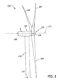
- FIG. 1 is a side perspective view of an exemplary wind turbine 100.
- wind turbine 100 is a horizontal axis wind turbine generator.
- wind turbine 100 may be a vertical axis wind turbine generator.
- the terms "wind turbine” and “wind turbine generator” are used interchangeably, and are representative of any device that converts wind energy to electrical energy and, more specifically, converts kinetic energy of wind into mechanical energy that generates electricity using a generator.
- Wind turbine 100 includes a rotor 102 that includes a plurality of rotor blades 104 coupled to a rotatable hub 106.
- Wind turbine 100 also includes a nacelle 107 that houses a generator 108 therein and that is coupled to rotatable hub 106.
- rotor 102 includes three rotor blades 104.
- rotor 102 may include any suitable number of rotor blades 104 that enables wind turbine 100 to function as described herein.
- generator 108 is coupled to a support tower 110 that supports wind turbine 100 during operation.
- wind forces act upon rotor blades 104 causing rotor 102 to rotate about an axis 112 of generator 108 and generate electrical power.
- stresses created by the force of the wind upon rotor blades 104, hub 106, generator portion 108, and support tower 110, as well as operational parameters such as power output and temperature are measured by one or more sensors and/or determined by one or more programmable logic controllers (PLC) as described below, and the resulting measured and/or determined operational data, is transmitted to a renewable power generation management system, such as a wind power generation system 200 shown in Figures 2 and 3 for example.
- PLC programmable logic controller
- each wind turbine 100 includes a control system 114, shown in Figures 1 , 2 , 3 , and 7 , that is operatively coupled, such as in signal communication, with wind power generation system 200 to facilitate controlling operation of corresponding wind turbine 100.
- Control system 114 is shown as being positioned on or within tower 110, such as at a base of tower 110. However, in alternative embodiments, control system 114 or at least a portion of control system 114 is centralized within nacelle 107 or is a distributed system throughout wind turbine 100, within a wind farm, and/or at a remote control center, such as at wind power generation system 200.
- Control system 114 includes a processor configured to perform the methods and/or steps described herein.
- processors are not limited to integrated circuits referred to in the art as a computer, but broadly refers to a controller, a microcontroller, a microcomputer, a programmable logic controller (PLC), an application specific integrated circuit, and other programmable circuits, and these terms are used interchangeably herein. It should be understood that a processor and/or control system or controller can also include memory, input channels, and/or output channels.
- PLC programmable logic controller
- memory may include, without limitation, a computer-readable medium, such as a random access memory (RAM), and a computer-readable non-volatile medium, such as flash memory.
- a computer-readable medium such as a random access memory (RAM)
- a computer-readable non-volatile medium such as flash memory.
- a floppy disk, a compact disc-read only memory (CD-ROM), a magneto-optical disk (MOD), and/or a digital versatile disc (DVD) may also be used.
- the input channels described herein may include, without limitation, sensors and/or computer peripherals associated with an operator interface, such as a mouse and a keyboard
- the output channels described herein may include, without limitation, a control device, an operator interface monitor and/or a display.
- Processors described herein process information transmitted from a plurality of electrical and electronic devices that may include, without limitation, sensors, actuators, compressors, control systems, and/or monitoring devices. Such processors may be physically located in, for example, a control system, a sensor, a monitoring device, a desktop computer, a laptop computer, a PLC cabinet, and/or a distributed control system (DCS) cabinet.
- RAM and storage devices store and transfer information and instructions to be executed by the processor(s). RAM and storage devices can also be used to store and provide temporary variables, static (i.e., non-changing) information and instructions, or other intermediate information to the processors during execution of instructions by the processor(s). Instructions that are executed may include, without limitation, flow control system control commands. The execution of sequences of instructions is not limited to any specific combination of hardware circuitry and software instructions.
- Control system 114 is operatively coupled to one or more components of wind turbine 100, such as in operational control communication, to monitor and/or control operation of wind turbine 100.
- Control system 114 includes one or more sensors that are configured to measure environmental conditions, such as a wind speed, a direction or wind, and various climate conditions, as well as a speed of rotation of rotor blades 104, for example. The sensors provide feedback of the measured environmental and/or operational conditions to control system 114.
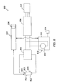
- FIG. 2 is a schematic block diagram of an exemplary renewable power generation system, namely wind power generation system 200.
- Wind power generation system 200 includes one or more wind power generators 202 operatively coupled to or including, for example, one or more wind turbines 100, as a renewable power source.
- An AC/DC converter 204 is electrically coupled to wind power generator 202 and a DC/AC converter 206 is electrically coupled to AC/DC converter 204.
- a DC link 208 is electrically coupled to wind power generator 202 and coupled between AC/DC converter 204 and DC/AC converter 206.
- DC/AC converter 206 is electrically coupled to a transformer 210 which is electrically coupled to an electrical grid 212.
- electrical grid 212 includes a microgrid including, for example, electrical generators, loads, and storage devices. Electrical grid 212 supplies power or distributes electrical energy, for example, to shopping centers, industrial parks, college campuses, city neighborhoods, towns and/or villages.
- DC link 208 is also electrically coupled to a pump load 214 including a bi-directional DC-DC converter 216 that is electrically coupled to a load 218.
- load 218 includes DC motor 220 located at a waste management site 222, such as a remotely located waste management plant or facility.
- wind power generation system 200 includes a thermal energy storage device 223 configured to store excess energy not required by pump load 214.
- wind power generator 202 generates a first AC voltage.
- AC-DC converter 204 converts the first AC voltage to a first DC voltage wherein at least a portion of the first DC voltage is transmitted to electrical grid 212.
- DC/AC converter 206 converts a portion of the first DC voltage from AC/DC converter 204 to a second AC voltage which is then transmitted through transformer 210 to electrical grid 212.
- Bi-directional DC-DC converter 216 converts a portion of the first DC voltage from AC/DC converter 204 received through DC link 208 to a second DC voltage and supplies the second DC voltage to DC motor 220.
- bi-directional DC-DC converter 216 is electrically coupled to wind power generator 202 and coupled between AC/DC converter 204 and DC/AC converter 206.
- a suitable renewable power generation management system namely a wind power generation management system 224 is operatively coupled, such as in signal communication, with one or more wind power generators 202.
- wind power generation management system 224 is operatively coupled, such as in signal communication, with control system 114 of each wind turbines 100.
- wind power generation management system 224 may be operatively coupled, such as in signal communication, with one or more additional components of wind power generation system 200, including electrical grid 212, pump load 214, and/or waste management site 222.
- Wind power generation management system 224 is configured to monitor and/or control operation of the one or more wind power generators 202, including corresponding wind turbines 100, collectively or independently, for example to supply sufficient power to pump load 214.
- Wind power generation management system 224 includes a controller 230 that is operatively coupled to each wind power generator 202. In alternative embodiments, controller 230 is directly or indirectly coupled to one or more components of wind power generation system 200.
- a renewable power generation system such as wind power generation system 200, is configured to utilize excess energy generated by wind power generation system 200 to treat organic waste material to generate crude oil.
- Wind power generation system 200 includes one or more wind power generators 202 configured to generate electrical energy.
- Pump load 214 is operatively coupled to the wind power generators 202 and is configured to receive the excess energy generated by wind power generators 202.
- Controller 230 is programmed to receive operational data from pump load 214 related to current energy requirements and/or anticipated energy requirements at waste management site 222 for treating the organic waste material.
- Controller 230 is also programmed to receive operational data from electrical grid 212, operatively coupled to wind power generation system 200, related to a current electrical distribution load and/or an anticipated electrical distribution load.
- controller 230 is programmed to determine an amount of excess energy to supply to pump load 214 to facilitate treating the organic waste material to generate crude oil.
- controller 230 is further programmed to consider current loads, a load forecast, market conditions, current thermal energy storage, and/or thermal energy storage capacity to determine based at least in part on anticipated energy requirements an amount of excess energy to transmit to pump load 214.
- Controller 230 is further programmed to operate wind power generators 202 to generate electrical energy based at least in part on the anticipated energy requirements and the anticipated electrical distribution load.
- controller 230 is programmed to operate bi-directional DC-DC converter 216 to supply the determined amount of excess energy to load 218.
- Controller 230 is further programmed to generate and transmit to each wind power generator 202 command signals to control an amount of electrical energy generated by each wind power generator 202 based at least in part on the anticipated energy requirements and the anticipated electrical distribution load.
- wind power generation system 200 includes wind power generation management system 224 having controller 230 for use in monitoring operation of each wind power generator 202 and/or each wind turbine 100.
- controller 230 includes a memory storage unit 232 that stores information and data used by controller 230 to operate, to retrieve, and/or to store operational data related to each wind turbine 100.
- memory storage unit 232 may include internal and/or external storage such as a hard drive, Read Only Memory (ROM), Random Access Memory (RAM), or any other suitable device known to those skilled in the art for performing the functions as described herein.
- Controller 230 is communicatively coupled to a server sub-system 234 and to a user interface device 236 that includes an input and an output.
- server sub-system 234 includes a data storage unit 238 and a database unit 240.
- data storage unit 238 and database unit 240 receive data from controller 230, store the received data, receive requests for stored data, and/or retrieve stored data in response to the received requests.
- data storage unit 238 includes a supervisory control and data acquisition (SCADA) system configured to acquire operational data from wind power generation system 200 and/or one or more operating wind turbines 100 and transmit the acquired operational data to controller 230.
- SCADA supervisory control and data acquisition
- database unit 240 stores and retrieves data based on requests received from controller 230 for data stored in one or more databases, such as in a historical data database 242, in an operational data database 244, and in a configuration database 246 that includes configuration data for each wind turbine 100.
- user interface device 236 outputs data through a user output device 248 and receives data through a user input device 250.
- the operational data received by controller 230 from operating wind turbine 100 may include data from one or more sensors 255 and/or one or more programmable logic controllers (PLC) 252 each positioned on or with respect to wind turbine 100, such as measurements representative of the present operational status of various components of wind turbine 100.
- PLC programmable logic controllers
- the operational data may include, without limitation, information or data related to current power generation and/or anticipated power generation, a number of operational renewable power generators within the renewable power generation system available to generate useable electrical energy, a maximum power generation of each renewable power generator and/or of the renewable power generation system, heating requirements of the renewable power generator, cooling requirements of the renewable power generator, current climate conditions, and/or a climate conditions forecast, as well as a temperature of one or more wind turbine component, a power output of wind power generator 202, stresses or forces acting upon one or more wind turbine component, and/or any other suitable measurement.
- user interface 236 outputs the operational data via user output device 248 using at least one of a visual display, a graphical user interface (GUI) 254, a hardcopy device, and/or an audio device. Further, in addition to the operation of controller 230 using operational data, controller 230 may also transmits to server sub-system 234 requests for historical data associated with one or more wind turbines 100, and receives historical data in response to such requests.
- GUI graphical user interface
- wind power generation management system 224 receives through user interface device 236 input from a user 256 via GUI 254 and that receives input from other than user 256 via user input device 250.
- controller 230 is coupled to an external storage unit 258 for storage and retrieval of operational data, similar to the function of internal memory storage unit 232.
- wind power generation management system 224 enables user 256 to amass operational data for use in monitoring and/or controlling operation of wind power generation system 200.
- wind power generation management system 224 is communicatively coupled to an operating wind turbine 260 that is located remotely from wind turbine 100.
- the ability of wind power generation management system 224 to monitor remote operating wind turbine 260 in the same manner as local operating wind turbine 100 enables an operator to monitor wind turbine farms, during operation, that are remotely located from wind power generation management system 224.
- Such a feature enables centralized monitoring of multiple disparate wind turbine farms, in such an embodiment.
- wind power generation management system 224 is configured to facilitate utilization of excess energy generated by wind power generation system 200 including wind power generator 202 to treat organic waste material to generate crude oil.
- wind power generation management system 224 includes controller 230 programmed to receive operational data from pump load 214 operatively coupled to wind power generator 202. The operational data is related to current energy requirements and/or anticipated energy requirements for treating the organic waste material.
- Controller 230 is further programmed to receive operational data from electrical grid 212 operatively coupled to wind power generator 202.
- Controller 230 is programmed to determine, based at least in part on anticipated energy requirements, an amount of excess energy to supply to pump load 214 to facilitate treating the organic waste material to generate crude oil, and operate wind power generator 202 to generate electrical energy based at least in part on the anticipated energy requirements and/or the anticipated electrical distribution load. Controller 230 is further programmed to supply the determined amount of excess energy to pump load 214. In a particular embodiment, controller 230 is further programmed to operate bi-directional DC-DC converter 216, shown in Figure 2 , or a bi-directional inverter operatively coupled to a renewable power generator as described in greater detail below to supply the determined amount of excess energy to pump load 214.
- Controller 230 is further programmed to consider current loads, a load forecast, market conditions, current thermal energy storage, and thermal energy storage capacity to determine based at least in part on anticipated energy requirements an amount of excess energy to transmit to pump load 214. Controller 230 then generates and transmits to one or more wind power generators 202 command signals to control an amount of power generated by each wind power generator 202 based at least in part on the anticipated energy requirements and the anticipated electrical distribution load.
- FIG 4 is a schematic block diagram of an exemplary waste management site 222 including a microwave cracking reactor unit 400 powered by DC motor 220, referred to above with reference to Figure 2 .
- excess electrical energy generated utilizing a renewable power generator system such as a suitable wind power generation system or a suitable solar power generation system as described herein, may be supplied to microwave cracking reactor unit 400 by DC motor 220.
- DC Motor 220 is operatively coupled to an extruder/separator 402 of microwave cracking reactor unit 400 and configured to supply electrical energy to extruder/separator 402 to drive or rotate extruder/separator 402.
- DC Motor 220 is configured to supply electrical energy to one or more components of microwave cracking reactor unit 400 in addition to or as an alternative to extruder/separator 402.
- At least one microwave cracking reactor 404 is coupled in communication with extruder/separator 402.
- An organic waste material feeder 406 feeds waste feed material into extruder/separator 402, wherein plastic material contained in the waste feed material is separated from non-plastic material.
- the waste feed material may include, without limitation, non-plastic contaminants, such as paper, pieces of metal and wood, and plastic material having various compositions of polymers which undergo different cracking reactions. Separated plastic material is then extruded into one or more cracking reactors 404, wherein the plastic material undergoes a microwave cracking process.
- extruder/separator 402 includes a main extruder 410 that functions as a separator. Extruder/separator 402 also includes one or more sections that have openings 412 in a wall 414 of extruder/separator 402. A diameter and a location of each opening 412, as well as a distribution of openings 412 enables the molten plastic material to be extruded such that the solid pieces and particles remain inside extruder/separator 402. Non-plastic material in the waste feed material (paper labels, pieces of metal, wood, fabric, glass, etc.) is removed towards an end 416 of extruder/separator 402 since the non-plastic material does not pass through openings 412.
- a main screw conveyor 418 has blades which facilitate cleaning openings 412 and removing plugging material.
- Plastic material extruded at a particular section of main screw conveyor 418 is mixed with specific catalysts and additives and is supplied to a separate cracking reactor 404. In some applications, the material extruded at different sections is mixed together and is processed in one cracking reactor 404.
- Plastic material that is mixed with a sensitizer, catalyst and additive, is extruded into cracking reactor 404 in the form of strands or sheets, for example, to facilitate increasing a surface area and/or to increase a thickness of the material into a desired range of the penetration depth for the microwave/radio frequency power.
- the material undergoes thermal/catalytic cracking under microwave irradiation.
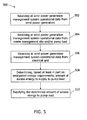
- FIG. 5 is a flow chart of an exemplary method 500 for using excess energy generated by a renewable power generation system including at least one renewable power generator to treat organic waste material to generate crude oil.
- the renewable power generation system includes a suitable controller to control operation of the renewable power generation system. The controller determines an amount of electrical power to utilize and store.
- method 500 includes receiving 502 at wind power generation management system 224 operational data from one or more wind power generators 202.
- the operational data received from wind power generator 202 includes data related to current power generation and/or anticipated power generation, a number of operational renewable power generators, a maximum power generation, heating requirements of the renewable power generator, cooling requirements of the renewable power generator, current climate conditions, and/or a climate conditions forecast.
- Wind power generation management system 224 also receives 504 operational data from waste management site 222 and/or pump load 214 operatively coupled to wind power generator 202.
- the operational data received from pump load 214 is related to current energy requirements and/or anticipated energy requirements for treating the organic waste material at waste management site 222.
- the operational data from pump load 214 may include data related to current energy requirements and/or anticipated energy requirements, a quantity of organic waste material, crude oil demand, waste disposal cost, electricity cost, and crude oil pricing.
- Wind power generation management system 224 also receives 506 operational data from electrical grid 212 operatively coupled to wind power generator 202.
- the operational data received from electrical grid 212 is related to a current electrical distribution load and/or an anticipated electrical distribution load.
- the operational data received from electrical grid 212 may include data related to current climate conditions, a climate conditions forecast, a maximum capacity of the electrical grid, energy demands at peak hours and non-peak hours, energy demands at a selected time of day, and/or energy demands on a selected day.
- wind power generation management system 224 determines 508 an amount of excess energy to supply to pump load 214 to facilitate treating the organic waste material to generate crude oil. The determined amount of excess energy is supplied 510 to pump load 214.
- controller 230 maintains a sufficient supply of electrical energy to waste management site 222 to ensure that a minimum temperature within microwave cracking reactor unit 400 is maintained to prevent the organic waste material from cooling if the electrical energy is supplied to electrical grid 212.
- an amount of renewable power generated by the renewable power generator is quantified.
- a determination is made 602 whether wind power is available. If wind power is available, a determination is made 604 whether the current or anticipated electrical distribution load required by electrical grid 212 is equal to or greater than the available wind power. If the current or anticipated electrical distribution load required by electrical grid 212 is equal to or greater than the available wind power, the wind power is sold 606 in the energy market. A decision to sell the available wind power at this point may be driven by market considerations and/or forecast input.
- wind power generation management system 224 may cease operation 616 of one or more wind power generators 202. Alternatively, or in addition, the determination may be made 618 as to whether any component of wind power generator 202 requires any heating or cooling. If one or more components require heating or cooling, a suitable amount of energy is output 620 from the thermal energy storage unit or device to facilitate heating or cooling the component(s).
- wind power generation management system 224 determines 508, based at least in part on anticipated energy requirements, an amount of excess energy to supply to pump load 214
- wind power generation management system 224 considers current loads, a load forecast, market conditions, current thermal energy storage, and/or thermal energy storage capacity.
- wind power generation management system 224 is configured to generate and transmit to wind power generator 202 command signals through controller 230 to control an amount of power generated by wind power generator 202 based at least in part on the anticipated energy requirements and/or the anticipated electrical distribution load.
- FIG. 7 is a schematic block diagram of an alternative exemplary wind power generation system 700.
- Wind power generation system 700 includes at least some components that are similar to the components described above in reference to wind power generation system 200 and, therefore, are described herein and identified with similar component reference numbers in Figure 7 .
- Wind power generation system 700 includes one or more wind power generators 202 operatively coupled to or including, for example, one or more wind turbines 100, as a renewable power source.
- AC/DC converter 204 is electrically coupled to wind power generator 202.
- DC/AC converter 206 is electrically coupled to AC/DC converter 304.
- DC link 208 is electrically coupled to wind power generator 202 and coupled between AC/DC converter 204 and DC/AC converter 206.
- DC/AC converter 206 is electrically coupled to transformer 210 which is electrically coupled to electrical grid 212 described above.
- a pump load 714 including a bi-directional DC-AC converter 716 is electrically coupled to wind power generator 202 and coupled between DC/AC converter 206 and transformer 210.
- Pump load 714 is configured to supply power to a load 718.
- load 718 includes an AC motor 720 located at waste management site 222, such as a remotely located waste management plant or facility.
- wind power generation system 700 includes thermal energy storage device 223 configured to store excess energy not required by pump load 714.
- wind power generator 202 generates a first AC voltage.
- AC-DC converter 204 converts the first AC voltage to a first DC voltage.
- DC/AC converter 206 converts a portion of the first DC voltage from AC/DC converter 204 to a second AC voltage. At least a portion of the second AC voltage is transmitted to electrical grid 212 through transformer 210.
- DC-AC converter 716 converts a portion of the second AC voltage from DC/AC converter 206 to a third AC voltage. The third AC voltage is then transmitted to AC motor 720.
- bi-directional DC-AC converter 716 is coupled downstream from DC/AC converter 206.
- the second AC voltage is transmitted to transformer 210 prior to being transmitted to electrical grid 212.
- a suitable renewable power generation management system namely wind power generation management system 224 is operatively coupled, such as in signal communication, with one or more wind power generators 202. Further, wind power generation management system 224 may be operatively coupled, such as in signal communication, with one or more additional components of wind power generation system 700, including electrical grid 212, pump load 714, and/or waste management site 222. Wind power generation management system 224 is configured to monitor and/or control operation of the one or more wind power generators 202, including corresponding wind turbines 100, collectively or independently, for example to supply sufficient power to pump load 714.
- Wind power generation management system 224 includes controller 230 that is coupled to each wind power generator 202. In alternative embodiments, controller 230 is directly or indirectly coupled to one or more components of wind power generation system 700.
- wind power generation system 700 is configured to utilize excess energy generated by wind power generation system 700 to treat organic waste material to generate crude oil, as described above with reference to wind power generation system 200.
- Pump load 714 is operatively coupled to wind power generators 202 and is configured to receive the excess energy generated by wind power generators 202.
- Controller 230 is programmed to receive operational data and monitor and/or control operation of wind power generation system 700.
- FIG 8 is a schematic block diagram of an exemplary renewable power generation system, namely a solar power generation system 800.
- Solar power generation system 800 includes at least some components that are similar to the components described above in reference to wind power generation system 200 and, therefore, are described herein and identified with similar component reference numbers in Figure 8 .
- solar power generation system 800 includes one or more solar power generators 802 that include one or more solar panels or photovoltaic cells 803.
- Solar power generator 802 is provided to generate a DC voltage utilizing solar energy. More specifically, in one embodiment, each solar power generator 802 includes a local control system 804 operatively coupled to photovoltaic cells 803.
- each solar power generator 802 includes control system 804, such as shown in Figures 8 and 9 , that is operatively coupled, such as in signal communication, with solar power generation system 800 to facilitate controlling operation of corresponding solar power generator 802.
- Control system 804 includes a processor configured to perform the methods and/or steps described herein. Further, the processor and/or control system 804 can also include memory, input channels, and/or output channels.
- Control system 804 is operatively coupled to one or more components of solar power generator 802, such as in operational control communication, to monitor and/or control operation of solar power generator 802.
- Control system 804 includes one or more sensors that are configured to measure environmental and climate conditions, as well as operational conditions of solar power generator 802, for example. The sensors provide feedback of the measured environmental and/or operational conditions to control system 804.
- Photovoltaic cells 803 generate a DC voltage from solar energy received by solar power generator 802.
- a DC boost 805 is electrically coupled to each solar power generator 802.
- a DC/AC inverter 806 is electrically coupled to DC boost 805.
- Solar power generation system 800 is electrically coupled to a load 818.
- load 818 includes a DC motor 820 located at waste management site 222, such as a remotely located waste management plant or facility.
- DC motor 820 is coupled between DC boost 805 and DC/AC inverter 806.
- DC motor 820 receives a portion of the boosted DC voltage from DC boost 805.
- solar power generator 802 generates a DC voltage.
- DC boost 805 is electrically coupled to solar power generator 802 and is configured to boost the DC voltage from solar power generator 802 to provide a boosted DC voltage.
- DC/AC inverter 806 inverts a portion of the boosted DC voltage from DC boost 805 to an AC voltage. At least a portion of the AC voltage is transmitted to electrical grid 212.
- solar power generation system 800 includes a thermal energy storage device 223 configured to store excess energy not required by load 818.
- a suitable renewable power generation management system namely a solar power generation management system 824 is operatively coupled, such as in signal communication, with one or more solar power generator 802.
- solar power generation management system 824 is operatively coupled, such as in signal communication, with control system 804 of each solar power generator 802.
- solar power generation management system 824 may be operatively coupled, such as in signal communication, with one or more additional components of solar power generation system 800, including electrical grid 212, load 818, and/or waste management site 222.
- Solar power generation management system 824 is configured to monitor and/or control operation of the one or more solar power generators 802, collectively or independently, for example to supply sufficient power to load 818.
- Solar power generation management system 824 includes a controller 830 that is operatively coupled to each solar power generator 802. In alternative embodiments, controller 830 is directly or indirectly coupled to one or more components of solar power generation system 800.
- solar power generation system 800 is configured to utilize excess energy generated by solar power generation system 800 to treat organic waste material to generate crude oil.
- Solar power generation system 800 includes one or more solar power generator 802 configured to generate electrical energy.
- Load 818 is operatively coupled to solar power generator 802 and is configured to receive the excess energy generated by solar power generator 802.
- Controller 830 is programmed to receive operational data from load 818 related to current energy requirements and/or anticipated energy requirements at waste management site 222 for treating the organic waste material.
- Controller 830 is also programmed to receive operational data from electrical grid 212, operatively coupled to solar power generation system 800, related to a current electrical distribution load and/or an anticipated electrical distribution load.
- controller 830 is programmed to determine an amount of excess energy to supply to load 818 to facilitate treating the organic waste material to generate crude oil.
- controller 830 is further programmed to consider current loads, a load forecast, market conditions, current thermal energy storage, and/or thermal energy storage capacity to determine based at least in part on anticipated energy requirements an amount of excess energy to transmit to load 818.
- Controller 830 is further programmed to operate solar power generator 802 to generate electrical energy based at least in part on the anticipated energy requirements and the anticipated electrical distribution load.
- Controller 830 is further programmed to generate and transmit to each solar power generator 802 command signals to control an amount of electrical energy generated by each solar power generator 802 based at least in part on the anticipated energy requirements and the anticipated electrical distribution load.
- solar power generation system 800 includes solar power generation management system 824 having controller 830 for use in monitoring operation of each solar power generator 802.
- controller 830 includes components similar to the components described in reference to wind power generation management system 224 described above in reference to Figure 3 .
- data storage unit 238 includes a supervisory control and data acquisition (SCADA) system configured to acquire operational data from solar power generation system 800 and/or one or more operating solar power generators 802 and transmit the acquired operational data to controller 830.
- SCADA supervisory control and data acquisition
- solar power generation management system 824 includes a database unit 240 (see Figure 3 ) that stores and retrieves data based on requests received from controller 830 for data stored in one or more databases, such as in a historical data database, in an operational data database, and in a configuration database that includes configuration data for each solar power generator 802.
- a user interface device outputs data through a user output device and receives data through a user input device.
- the operational data received by controller 830 from operating solar power generator 802 may include data from one or more sensors 855 and/or one or more programmable logic controllers (PLC) 852 each positioned on or with respect to solar power generator 802, such as measurements representative of the present operational status of various components of solar power generator 802.
- PLC programmable logic controller
- the operational data may include, without limitation, information or data related to current power generation and/or anticipated power generation, a number of operational solar power generator 802 within solar power generation system 200 available to generate useable electrical energy, a maximum power generation of each solar power generator 802 and/or of solar power generation system 200, heating requirements of solar power generator 802, cooling requirements of solar power generator 802, current climate conditions, and/or a climate conditions forecast, as well as a temperature of one or more solar power component, a power output of solar power generator 802, stresses or forces acting upon one or more solar power generator component, and/or any other suitable measurement.
- solar power generation management system 824 is configured to facilitate utilization of excess energy generated by solar power generation system 800 including solar power generator 802 to treat organic waste material to generate crude oil.
- solar power generation management system 824 includes controller 830 programmed to receive operational data from load 818 operatively coupled to solar power generator 802. The operational data is related to current energy requirements and/or anticipated energy requirements for treating the organic waste material.
- Controller 830 is further programmed to receive operational data from electrical grid 212 operatively coupled to solar power generator 802. The operational data is related to a current electrical distribution load and/or an anticipated electrical distribution load.
- Controller 830 is programmed to determine, based at least in part on anticipated energy requirements, an amount of excess energy to supply to load 818 to facilitate treating the organic waste material to generate crude oil, and operate solar power generator 802 to generate electrical energy based at least in part on the anticipated energy requirements and/or the anticipated electrical distribution load. Controller 830 is further programmed to supply the determined amount of excess energy to load 818. Controller 830 is further programmed to consider current loads, a load forecast, market conditions, current thermal energy storage, and thermal energy storage capacity to determine based at least in part on anticipated energy requirements an amount of excess energy to transmit to load 818. Controller 830 then generates and transmits to one or more solar power generators 802 command signals to control an amount of power generated by each solar power generator 802 based at least in part on the anticipated energy requirements and the anticipated electrical distribution load.
- FIG 9 is a schematic block diagram of an alternative exemplary solar power generation system 900.
- Solar power generation system 900 includes at least some components that are similar to the components described above in reference to wind power generation system 200 and solar power generation system 800 and, therefore, are described herein and identified with similar component reference numbers in Figure 8 .
- Solar power generation system 900 includes one or more solar power generators 802 that include one or more solar panels or photovoltaic cells 803.
- Solar power generator 802 is provided to generate a DC voltage utilizing solar energy. More specifically, in one embodiment, each solar power generator 802 includes a local controller operatively coupled to photovoltaic cells 803. Photovoltaic cells 803 generate a DC voltage from solar energy received by solar power generator 802.
- DC boost 805 is electrically coupled to each solar power generator 802.
- DC/AC inverter 806 is electrically coupled to DC boost 805.
- Solar power generation system 900 is electrically coupled to a load 918.
- load 918 includes an AC motor 920 located at waste management site 222, such as a remotely located waste management plant or facility.
- solar power generator 802 generates a DC voltage.
- DC boost 805 is electrically coupled to solar power generator 802 and is configured to boost the DC voltage from solar power generator 802 to provide a boosted DC voltage.
- DC/AC inverter 806 inverts at least a portion of the boosted DC voltage from DC boost 805 to an AC voltage. At least a portion of the AC voltage is transmitted to electrical grid 212. In one embodiment, a portion of the AC voltage from DC/AC inverter 806 is transmitted to AC motor 920. AC motor 920 is coupled downstream of DC/AC inverter 806.
- solar power generation system 900 includes a thermal energy storage device 223 configured to store excess energy not required by load 918.
- a suitable renewable power generation management system such as solar power generation management system 824 is operatively coupled, such as in signal communication, with one or more solar power generator 802 of solar power generation system 900. Further, solar power generation management system 824 may be operatively coupled, such as in signal communication, with one or more additional components of solar power generation system 900, including electrical grid 212, load 918, and/or waste management site 222. Solar power generation management system 824 is configured to monitor and/or control operation of the one or more solar power generators 802, collectively or independently, for example to supply sufficient power to load 918.
- Solar power generation management system 824 includes controller 830 that is coupled to each solar power generator 802. In alternative embodiments, controller 930 is directly or indirectly coupled to one or more components of solar power generation system 900.
- Solar power generation system 900 is configured to utilize excess energy generated by solar power generation system 900 to treat organic waste material to generate crude oil.
- Solar power generation system 900 includes one or more solar power generator 802 configured to generate electrical energy.
- Load 918 is operatively coupled to solar power generator 802 and is configured to receive the excess energy generated by solar power generator 802.
- Controller 830 is programmed to receive operational data from load 918 related to current energy requirements and/or anticipated energy requirements at waste management site 222 for treating the organic waste material. Controller 830 is also programmed to receive operational data from electrical grid 212, operatively coupled to solar power generation system 900, related to a current electrical distribution load and/or an anticipated electrical distribution load.
- controller 830 is programmed to determine an amount of excess energy to supply to load 918 to facilitate treating the organic waste material to generate crude oil.
- controller 830 is further programmed to consider current loads, a load forecast, market conditions, current thermal energy storage, and/or thermal energy storage capacity to determine based at least in part on anticipated energy requirements an amount of excess energy to transmit to load 918.
- Controller 830 is further programmed to operate solar power generator 802 to generate electrical energy based at least in part on the anticipated energy requirements and the anticipated electrical distribution load.
- Controller 830 is further programmed to generate and transmit to each solar power generator 802 command signals to control an amount of electrical energy generated by each solar power generator 802 based at least in part on the anticipated energy requirements and the anticipated electrical distribution load.
- solar power generation system 900 includes solar power generation management system 824 having controller 830 for use in monitoring operation of each solar power generator 802.
- a method for using excess energy generated by a renewable power generation system including at least one renewable power generator to treat organic waste material to generate crude oil.
- a renewable power generation management system receives operational data from the renewable power generator as well as operational data from a pump load operatively coupled to the renewable power generator.
- the operational data from the renewable power generator may include data related to at least one of current power generation and anticipated power generation, a number of operational renewable power generators, a maximum power generation, heating requirements of the renewable power generator, cooling requirements of the renewable power generator, current climate conditions, and a climate conditions forecast.
- the operational data from the pump load includes information or data related to current energy requirements and/or anticipated energy requirements for treating the organic waste material including, without limitation, data related to a quantity of organic waste material, crude oil demand, waste disposal cost, electricity cost, and crude oil pricing.
- the renewable power generation management system also receives operational data from an electrical grid that is operatively coupled to the renewable power generator.
- the operational data received from the electrical grid includes information or data related to a current electrical distribution load and/or an anticipated electrical distribution load.
- the operational data from the electrical grid may also include data related to current climate conditions, a climate conditions forecast, a maximum capacity of the electrical grid, energy demands at peak hours and non-peak hours, energy demands at a selected time of day, and energy demands on a selected day.
- the renewable power generation management system determines an amount of excess energy to supply to the pump load to facilitate treating the organic waste material to generate crude oil. Consideration may be given to current loads, a load forecast, market conditions, current thermal energy storage, and/or thermal energy storage capacity.
- the renewable power generation system then supplies the determined amount of excess energy to the pump load.
- a bi-directional converter or a bi-directional inverter operatively coupled to the renewable power generator is operated to supply the determined amount of excess energy to the pump load.
- the excess energy is converted to one of an AC voltage and a DC voltage utilizing one of the bi-directional converter and the bi-directional inverter before supplying the determined amount of excess energy to the pump load.
- the renewable power generation management system is configured to generate and transmit one or more renewable power generators command signals to control an amount of power generated by the renewable power generators based at least in part on the anticipated energy requirements and the anticipated electrical distribution load.
- the renewable power generation management system quantifies an amount of renewable power generated by the renewable power generator, determines whether the amount of renewable power generated exceeds the current electrical distribution load of the electrical grid, and if the amount of renewable power generated does not exceed the current electrical distribution load of the electrical grid, the renewable power generation management system supplies the amount of renewable power generated to the electrical grid. However, if the amount of renewable power generated exceeds the current electrical distribution load of the electrical grid, the renewable power generation management system quantifies an amount of energy required by the pump load and stores at a thermal energy storage device excess energy not required by the pump load.
- Various technical effects of the method, systems, and controller described herein include, for example: receiving at a renewable power generation management system operational data from the renewable power generator; receiving at the renewable power generation management system operational data from a pump load operatively coupled to the renewable power generator, the operational data related to at least one of current energy requirements and anticipated energy requirements for treating the organic waste material; receiving at the renewable power generation management system operational data from an electrical grid operatively coupled to the renewable power generator, the operational data related to at least one of a current electrical distribution load and an anticipated electrical distribution load; determining based at least in part on anticipated energy requirements an amount of excess energy to supply to the pump load to facilitate treating the organic waste material to generate crude oil; and supplying the determined amount of excess energy to the pump load.
- the loads may represent simple impedance loads, motor loads, or loads with power electronic interfaces, as well as energy storage devices such as batteries.
- the load may include a system having a plastic feed stock configured to recycle waste plastic and produce oil crude.
- the load is supplied with power to operate a microwave cracking facility. For example, it is estimated that a 20 ton microwave cracking facility requires about 100 to 150 Kilowatts of electricity. As such, a GE 1.5 megawatt (MW) wind turbine at 35% capacity factor can handle approximately 100 tons of oil crude production per day.
- the waste plastics are reused as an energy source.
- the embodiments described herein efficiently use and/or store excess electricity generated by renewable energy sources, such as wind energy and solar energy that would otherwise be unused. Further, the embodiments described herein provide a low unit cost way to store and/or transport energy with high energy density utilizing a process that does not require any change to the current energy infrastructure while additionally solving an environmental problem of waste plastics.
Landscapes
- Engineering & Computer Science (AREA)
- Chemical & Material Sciences (AREA)
- Life Sciences & Earth Sciences (AREA)
- Power Engineering (AREA)
- Sustainable Development (AREA)
- Sustainable Energy (AREA)
- Combustion & Propulsion (AREA)
- Mechanical Engineering (AREA)
- General Engineering & Computer Science (AREA)
- Business, Economics & Management (AREA)
- Economics (AREA)
- Entrepreneurship & Innovation (AREA)
- Oil, Petroleum & Natural Gas (AREA)
- Strategic Management (AREA)
- Human Resources & Organizations (AREA)
- Wood Science & Technology (AREA)
- Quality & Reliability (AREA)
- Educational Administration (AREA)
- Development Economics (AREA)
- Game Theory and Decision Science (AREA)
- Chemical Kinetics & Catalysis (AREA)
- Organic Chemistry (AREA)
- Marketing (AREA)
- Operations Research (AREA)
- General Chemical & Material Sciences (AREA)
- Tourism & Hospitality (AREA)
- Physics & Mathematics (AREA)
- General Business, Economics & Management (AREA)
- General Physics & Mathematics (AREA)
- Theoretical Computer Science (AREA)
- Wind Motors (AREA)
- Supply And Distribution Of Alternating Current (AREA)
- Control Of Eletrric Generators (AREA)
- Processing Of Solid Wastes (AREA)
Applications Claiming Priority (1)
| Application Number | Priority Date | Filing Date | Title |
|---|---|---|---|
| US12/502,449 US7925387B2 (en) | 2009-07-14 | 2009-07-14 | Method and systems for utilizing excess energy generated by a renewable power generation system to treat organic waste material |
Publications (2)
| Publication Number | Publication Date |
|---|---|
| EP2292930A2 true EP2292930A2 (fr) | 2011-03-09 |
| EP2292930A3 EP2292930A3 (fr) | 2014-04-30 |
Family
ID=42223550
Family Applications (1)
| Application Number | Title | Priority Date | Filing Date |
|---|---|---|---|
| EP10168659.0A Withdrawn EP2292930A3 (fr) | 2009-07-14 | 2010-07-07 | Procédés et systèmes visant à utiliser le surplus d'énergie généré par les systèmes de production d'énergie renouvelable pour traiter les déchets organiques |
Country Status (3)
| Country | Link |
|---|---|
| US (1) | US7925387B2 (fr) |
| EP (1) | EP2292930A3 (fr) |
| CN (1) | CN101956665B (fr) |
Cited By (2)
| Publication number | Priority date | Publication date | Assignee | Title |
|---|---|---|---|---|
| CN112600243A (zh) * | 2020-12-10 | 2021-04-02 | 中腾微网(北京)科技有限公司 | 一种混合电网发电装置 |
| US12556004B2 (en) | 2023-10-04 | 2026-02-17 | Toyota Motor North America, Inc. | Managing renewable energy disruption |
Families Citing this family (25)
| Publication number | Priority date | Publication date | Assignee | Title |
|---|---|---|---|---|
| CN2878390Y (zh) * | 2006-04-07 | 2007-03-14 | 王新明 | 多功能全自动远程恒温供热废旧轮胎裂化装置 |
| US7996337B2 (en) * | 2007-10-15 | 2011-08-09 | General Electric Company | Method and system for remotely determining the reliability of a DC motor system |
| EP2317360A4 (fr) | 2008-08-25 | 2011-09-21 | Konica Minolta Opto Inc | Objectif d'imagerie, dispositif d'imagerie et terminal portatif |
| EP2159496A1 (fr) * | 2008-08-29 | 2010-03-03 | Vito NV | Contrôleur pour les systèmes d'alimentation électrique |
| CN101771294B (zh) * | 2010-03-05 | 2012-08-15 | 矽力杰半导体技术(杭州)有限公司 | 集合驱动控制电路及其控制方法 |
| US8359125B2 (en) | 2010-06-17 | 2013-01-22 | Sharp Laboratories Of America, Inc. | Energy management system to reduce the loss of excess energy generation |
| US9348394B2 (en) | 2010-09-14 | 2016-05-24 | Microsoft Technology Licensing, Llc | Managing computational workloads of computing apparatuses powered by renewable resources |
| US8812164B2 (en) * | 2010-10-12 | 2014-08-19 | Engineered Electric Company | Portable cogeneration system incorporating renewable energy sources |
| US20240154051A1 (en) * | 2010-10-28 | 2024-05-09 | Solar Chief, Llc | Telemetry system |
| US20120271576A1 (en) | 2011-04-22 | 2012-10-25 | Expanergy, Llc | Systems and methods for analyzing energy usage |
| US20120323382A1 (en) * | 2011-06-15 | 2012-12-20 | Expanergy, Llc | Systems and methods to assess and optimize energy usage for a facility |
| CN104303203B (zh) | 2011-11-28 | 2018-04-13 | 艾克潘尔基公司 | 能源搜索引擎方法及系统 |
| US9184593B2 (en) * | 2012-02-28 | 2015-11-10 | Microcoal Inc. | Method and apparatus for storing power from irregular and poorly controlled power sources |
| US9715261B2 (en) * | 2012-02-29 | 2017-07-25 | Thomas Wilkins | Continuous dynamic balancing of generation and loads |
| JP5868809B2 (ja) * | 2012-08-06 | 2016-02-24 | 株式会社東芝 | 発電プラントおよび熱供給方法 |
| CN103023320B (zh) | 2012-11-23 | 2014-09-03 | 矽力杰半导体技术(杭州)有限公司 | 一种高效率的双向直流变换器及其控制方法 |
| DE102013108879A1 (de) * | 2013-08-16 | 2015-02-19 | Rwe Effizienz Gmbh | Verfahren zum Betreiben eines Kraftwerkssystems |
| US9810480B2 (en) | 2015-06-12 | 2017-11-07 | Targeted Microwave Solutions Inc. | Methods and apparatus for electromagnetic processing of phyllosilicate minerals |
| US10230241B1 (en) * | 2015-09-30 | 2019-03-12 | The United States Of America, As Represented By The Secretary Of The Navy | Self-optimizing hybrid power system |
| CN105490380A (zh) * | 2015-12-28 | 2016-04-13 | 北京天诚同创电气有限公司 | 风力发电变桨系统中的供电装置 |
| WO2018175297A1 (fr) * | 2017-03-18 | 2018-09-27 | Brian Lee Moffat | Convertisseur d'énergie des vagues avec grille électrique de surface |
| US10908571B2 (en) * | 2019-03-18 | 2021-02-02 | Bigwood Technology, Inc. | Online multi-period power dispatch with renewable uncertainty and storage |
| US11429168B1 (en) * | 2021-02-19 | 2022-08-30 | Philip Rettger | Space-based data processing using available energy |
| US12297722B2 (en) | 2022-02-03 | 2025-05-13 | Saudi Arabian Oil Company | Total crude oil demand control from multiple oil stabilizer columns |
| CN114989840B (zh) * | 2022-05-26 | 2023-08-11 | 东南大学 | 一种耦合新能源发电的生物质梯级热解储能方法及装置 |
Family Cites Families (18)
| Publication number | Priority date | Publication date | Assignee | Title |
|---|---|---|---|---|
| US2180206A (en) * | 1937-12-21 | 1939-11-14 | Honnef Hermann | Wind-operated electrical power station |
| US4118282A (en) * | 1977-08-15 | 1978-10-03 | Wallace Energy Conversion, Inc. | Process and apparatus for the destructive distillation of high molecular weight organic materials |
| US6184427B1 (en) * | 1999-03-19 | 2001-02-06 | Invitri, Inc. | Process and reactor for microwave cracking of plastic materials |
| US6182584B1 (en) * | 1999-11-23 | 2001-02-06 | Environmental Solutions & Technology, Inc. | Integrated control and destructive distillation of carbonaceous waste |
| US6797126B2 (en) * | 2001-04-24 | 2004-09-28 | Reactive Energy Llc | Process for the desulphurization and upgrading fuel oils |
| JP3740099B2 (ja) * | 2002-08-06 | 2006-01-25 | 三菱重工業株式会社 | 電力ネットワーク管理システムおよび電力ネットワーク管理方法 |
| CN2621355Y (zh) * | 2003-06-10 | 2004-06-23 | 赵长鸣 | 电网剩余电能综合利用装置 |
| CN1556352A (zh) * | 2004-01-02 | 2004-12-22 | 赵长鸣 | 电能发、供、蓄自动平衡系统及剩余电能综合利用方法 |
| JP2005318665A (ja) * | 2004-04-27 | 2005-11-10 | Iwasaki Electric Co Ltd | 風力発電機と太陽光発電機の電力表示装置 |
| DE102004046701A1 (de) * | 2004-09-24 | 2006-04-06 | Aloys Wobben | Regeneratives Energiesystem |
| NZ565921A (en) * | 2005-07-15 | 2011-05-27 | Southwest Windpower Inc | Wind turbine and method of manufacture |
| US7315769B2 (en) * | 2005-10-31 | 2008-01-01 | General Electric Company | Multi-tier benefit optimization for operating the power systems including renewable and traditional generation, energy storage, and controllable loads |
| US7239035B2 (en) * | 2005-11-18 | 2007-07-03 | General Electric Company | System and method for integrating wind and hydroelectric generation and pumped hydro energy storage systems |
| US7378820B2 (en) * | 2005-12-19 | 2008-05-27 | General Electric Company | Electrical power generation system and method for generating electrical power |
| US7983799B2 (en) * | 2006-12-15 | 2011-07-19 | General Electric Company | System and method for controlling microgrid |
| US7991512B2 (en) * | 2007-08-28 | 2011-08-02 | General Electric Company | Hybrid robust predictive optimization method of power system dispatch |
| US20090173667A1 (en) * | 2008-01-03 | 2009-07-09 | Colorado Seminary | High power microwave petroleum refinement |
| US20100146927A1 (en) * | 2008-12-12 | 2010-06-17 | Mccutchen Co. | Hybrid power for cracking power plant co2 |
-
2009
- 2009-07-14 US US12/502,449 patent/US7925387B2/en not_active Expired - Fee Related
-
2010
- 2010-07-07 EP EP10168659.0A patent/EP2292930A3/fr not_active Withdrawn
- 2010-07-14 CN CN2010102357320A patent/CN101956665B/zh not_active Expired - Fee Related
Non-Patent Citations (1)
| Title |
|---|
| None |
Cited By (2)
| Publication number | Priority date | Publication date | Assignee | Title |
|---|---|---|---|---|
| CN112600243A (zh) * | 2020-12-10 | 2021-04-02 | 中腾微网(北京)科技有限公司 | 一种混合电网发电装置 |
| US12556004B2 (en) | 2023-10-04 | 2026-02-17 | Toyota Motor North America, Inc. | Managing renewable energy disruption |
Also Published As
| Publication number | Publication date |
|---|---|
| EP2292930A3 (fr) | 2014-04-30 |
| CN101956665A (zh) | 2011-01-26 |
| CN101956665B (zh) | 2013-08-07 |
| US7925387B2 (en) | 2011-04-12 |
| US20100138062A1 (en) | 2010-06-03 |
Similar Documents
| Publication | Publication Date | Title |
|---|---|---|
| US7925387B2 (en) | Method and systems for utilizing excess energy generated by a renewable power generation system to treat organic waste material | |
| Bhutto et al. | Greener energy: Issues and challenges for Pakistan—wind power prospective | |
| Manwell | Hybrid energy systems | |
| Lundsager et al. | Isolated systems with wind power | |
| KR20130039865A (ko) | 저속 풍력을 이용한 하이브리드 발전 시스템 | |
| Bataineh et al. | Optimal design of hybrid power generation system to ensure reliable power supply to the health center at Umm Jamal, Mafraq, Jordan | |
| Shaahid et al. | Techno-economic assessment of establishment of wind farms in different provinces of Saudi Arabia to mitigate future energy challenges | |
| Moarref et al. | Optimal scheduling of power system integrated with hydrogen vehicles and flexible resources: A hybrid uncertainty management method | |
| JP2017060375A (ja) | 再生可能エネルギーによる発電電力の電力供給方法およびそのシステム | |
| CN202417840U (zh) | 用于电网的能量储备输送调节系统 | |
| Ebert et al. | Successful high wind penetration into a medium sized diesel grid without energy storage using variable speed wind turbine technology | |
| Sameti et al. | Simulation of a ZEB electrical balance with aHybrid small wind/PV | |
| Tzen et al. | Wind technology design and reverse osmosis systems for off-grid and grid-connected applications | |
| Kumar et al. | Hybrid operational deployment of renewable energy—A distribution generation approach | |
| Obaidah et al. | Development of a Hybrid Power Generation System | |
| Shi et al. | Optimization of wind-marine hybrid power system configuration based on genetic algorithm | |
| CN116689464A (zh) | 一种适用于岛屿的分布式垃圾处理及能源供应系统 | |
| Dudek et al. | Investigations of an off-grid system based on a hybrid photovoltaic and wind turbine system with integrated hydrogen production located in Poland | |
| KR20160001338U (ko) | 타워형 풍력 및 태양광 복합발전기 | |
| Azmi et al. | Life Cycle Cost Analysis And Payback Period of 12-Kw Wind Turbine For a Remote Telecommunications Base Station In Malaysia. | |
| Kheshti et al. | A new control method of wind energy in power system | |
| CN214836862U (zh) | 一种海上风电与太阳能一体化技术设备 | |
| Jaiganesh et al. | Maximum power point tracking strategy for a new wind power system with super capacitor connected photovoltaic power generation system and supported to a distribution power grid. | |
| Chukwuorji et al. | Improving power generation in Nigeria: The solar and wind energy option | |
| Somireddi et al. | Design and fabrication of portable solar & wind energy based mobile and laptop charging station |
Legal Events
| Date | Code | Title | Description |
|---|---|---|---|
| PUAI | Public reference made under article 153(3) epc to a published international application that has entered the european phase |
Free format text: ORIGINAL CODE: 0009012 |
|
| AK | Designated contracting states |
Kind code of ref document: A2 Designated state(s): AL AT BE BG CH CY CZ DE DK EE ES FI FR GB GR HR HU IE IS IT LI LT LU LV MC MK MT NL NO PL PT RO SE SI SK SM TR |
|
| AX | Request for extension of the european patent |
Extension state: BA ME RS |
|
| PUAL | Search report despatched |
Free format text: ORIGINAL CODE: 0009013 |
|
| AK | Designated contracting states |
Kind code of ref document: A3 Designated state(s): AL AT BE BG CH CY CZ DE DK EE ES FI FR GB GR HR HU IE IS IT LI LT LU LV MC MK MT NL NO PL PT RO SE SI SK SM TR |
|
| AX | Request for extension of the european patent |
Extension state: BA ME RS |
|
| RIC1 | Information provided on ipc code assigned before grant |
Ipc: F03D 9/00 20060101AFI20140325BHEP Ipc: F02D 9/02 20060101ALI20140325BHEP Ipc: C10G 1/00 20060101ALI20140325BHEP |
|
| 17P | Request for examination filed |
Effective date: 20141030 |
|
| RBV | Designated contracting states (corrected) |
Designated state(s): AL AT BE BG CH CY CZ DE DK EE ES FI FR GB GR HR HU IE IS IT LI LT LU LV MC MK MT NL NO PL PT RO SE SI SK SM TR |
|
| 17Q | First examination report despatched |
Effective date: 20151027 |
|
| STAA | Information on the status of an ep patent application or granted ep patent |
Free format text: STATUS: THE APPLICATION IS DEEMED TO BE WITHDRAWN |
|
| 18D | Application deemed to be withdrawn |
Effective date: 20161220 |