EP2292957B1 - Dispositif de levier et soupape hydraulique dotée d'un tel dispositif de levier - Google Patents
Dispositif de levier et soupape hydraulique dotée d'un tel dispositif de levier Download PDFInfo
- Publication number
- EP2292957B1 EP2292957B1 EP20090011379 EP09011379A EP2292957B1 EP 2292957 B1 EP2292957 B1 EP 2292957B1 EP 20090011379 EP20090011379 EP 20090011379 EP 09011379 A EP09011379 A EP 09011379A EP 2292957 B1 EP2292957 B1 EP 2292957B1
- Authority
- EP
- European Patent Office
- Prior art keywords
- engagement
- locking
- lever device
- lever
- shaft
- Prior art date
- Legal status (The legal status is an assumption and is not a legal conclusion. Google has not performed a legal analysis and makes no representation as to the accuracy of the status listed.)
- Active
Links
Images

Classifications
-
- G—PHYSICS
- G05—CONTROLLING; REGULATING
- G05G—CONTROL DEVICES OR SYSTEMS INSOFAR AS CHARACTERISED BY MECHANICAL FEATURES ONLY
- G05G1/00—Controlling members, e.g. knobs or handles; Assemblies or arrangements thereof; Indicating position of controlling members
- G05G1/08—Controlling members for hand actuation by rotary movement, e.g. hand wheels
- G05G1/10—Details, e.g. of discs, knobs, wheels or handles
-
- F—MECHANICAL ENGINEERING; LIGHTING; HEATING; WEAPONS; BLASTING
- F16—ENGINEERING ELEMENTS AND UNITS; GENERAL MEASURES FOR PRODUCING AND MAINTAINING EFFECTIVE FUNCTIONING OF MACHINES OR INSTALLATIONS; THERMAL INSULATION IN GENERAL
- F16K—VALVES; TAPS; COCKS; ACTUATING-FLOATS; DEVICES FOR VENTING OR AERATING
- F16K35/00—Means to prevent accidental or unauthorised actuation
- F16K35/02—Means to prevent accidental or unauthorised actuation to be locked or disconnected by means of a pushing or pulling action
- F16K35/022—Means to prevent accidental or unauthorised actuation to be locked or disconnected by means of a pushing or pulling action the locking mechanism being actuated by a separate actuating element
- F16K35/025—Means to prevent accidental or unauthorised actuation to be locked or disconnected by means of a pushing or pulling action the locking mechanism being actuated by a separate actuating element said actuating element being operated manually (e.g. a push-button located in the valve actuator)
-
- G—PHYSICS
- G05—CONTROLLING; REGULATING
- G05G—CONTROL DEVICES OR SYSTEMS INSOFAR AS CHARACTERISED BY MECHANICAL FEATURES ONLY
- G05G5/00—Means for preventing, limiting or returning the movements of parts of a control mechanism, e.g. locking controlling member
- G05G5/06—Means for preventing, limiting or returning the movements of parts of a control mechanism, e.g. locking controlling member for holding members in one or a limited number of definite positions only
Definitions
- the present invention relates to a lever device for actuating in particular a hydraulic valve, comprising an actuating shaft for connection to the hydraulic valve and an actuating lever connected to the actuating shaft, by the handling of the actuating shaft is rotatable, and with a locking device for fixing the actuating shaft in a plurality of locking positions, wherein the locking means comprises an engaging member connected to the actuating shaft and / or the actuating lever and a rotatably mounted locking member and engaging and locking member complementary engagement elements, wherein the engagement member of the locking member from a release position outside the range of movement of the engagement member can be brought into an engaged position, in the form-fitting engaging the engagement elements of the engagement part and locking part and the actuating shaft, wherein the engagement element on the Ar retainer is mounted such that it can be pivoted by rotational movement of the locking part from the release position into the engaged position.
- the invention relates to a hydraulic valve with such a lever device.
- Lever devices of the above type are used in particular in agricultural machines and tractors to provide hydraulic valves for handling a working implement provided on the tractor, e.g. a plow, to operate.
- the actuating shaft is rotated via the actuating lever, so that via the hydraulic valve causes a lowering or lifting of the plow.
- locking means are known, with which the actuating shaft is held securely in at least one, usually a plurality of locking position.
- a known locking device comprises a threaded bolt rotatably held as a locking bolt, which can be screwed in the locking position in a corresponding recess of an engagement part which is connected to the actuating shaft.
- the disadvantage is that the locking of the actuating shaft is time-consuming and the production of the locking device is expensive.
- the DE-A-604 802 is a gas cock disclosed, which is provided with a lever device for its actuation.
- the lever device has an actuating shaft and an actuating lever coupled to the actuating shaft, by the handling of which the actuating shaft is rotatable.
- the lever device has a locking device for fixing the actuating shaft in a locking position.
- the locking device has a with the actuating shaft or the actuating lever connected engagement part and a locking part, wherein engaging and locking part mutually complementary engagement elements.
- the engagement element of the locking part can be brought from a release position into an engagement position in which the engagement elements of engagement part and locking part form-locking and the actuating shaft engage in a blocking manner.
- a disadvantage of this lever device is that the actuating lever must be pressed axially, so that engaging part and locking member can engage. This is not only mechanically complex, but also cumbersome in the operation.
- a lever device for the actuation of a valve wherein the lever device comprises an actuating shaft and an actuating lever. Connected to the actuating lever is a locking device for fixing the actuating shaft in a plurality of locking positions.
- the locking device has a disc connected to the actuating lever, which has engagement elements over its circumference.
- the assigned is a spring lever which has a complementary engagement element. The spring lever can be bent from a blocking position into a release position, so that then the actuating shaft is rotatable. The operation of the lever device is cumbersome, because it requires two hands.
- a valve is disclosed which is provided with a lever device for its actuation.
- a locking device is provided with a pivotable lever as a locking part, which allows that the valve can be fixed in a locking position.
- Object of the present invention is therefore to provide a lever device of the type mentioned above, which is easy to operate and has a simple structure.
- the locking part is designed as immovably mounted shaft in the axial direction, which has a rotary handle on its the engagement element opposite region, and that the engagement element is provided on the engagement part side end portion of the shaft, wherein the shaft is positioned in that its longitudinal axis is substantially perpendicular to the axis of the actuating shaft.
- the basic idea of the invention is thus to transfer the engagement element or the engagement elements of the locking part by a short rotation of the locking part, for example a quarter turn, from the engagement position into the release position or vice versa.
- a short rotation of the locking part for example a quarter turn
- there is a pivoting of the engagement member or the engagement elements so that it or, they blocked in the engaged position, an engagement element of the engagement member by positive engagement.
- the blocking of the engagement member of the engagement member causes the locking of the actuating shaft, wherein the locking member blocks the actuating shaft in a radial area, so that the resulting lever is short and only small forces act on it.
- the locking member can be kept short. Since the locking member has a rotary handle on its end portion opposite to the engaging member, the locking member can be manually rotated.
- the rotary handle can also be designed as a lever to allow the introduction of large rotational forces in the locking part.
- the engagement element of the locking part be formed as two spaced projections, between which the or the engagement element (s) can pass on the engagement part in the release position of the locking part or can.
- the two spaced protrusions include a groove therebetween which is aligned in the direction of movement of the engaging element (s) of the engaging part, whereas the two protrusions in the engaged position sandwich and lock the engaging element on the engaging part in the direction of movement.
- a particularly simple embodiment of the engagement element (s) of the engagement part results when it is or are formed as a projection or projections. Also, this may or may be the engaging element (s) of the engaging part extend substantially radially to the actuating shaft. This allows the Engagement with the engagement element of the locking member can be reliably brought about, and there is a secure blocking of the actuating shaft.
- the engagement part may comprise a plurality of engagement elements, wherein each engagement element of the engagement part can be brought into engagement with the engagement element of the locking part.
- each engagement element of the engagement part can be brought into engagement with the engagement element of the locking part.
- the lever device can thus take place a lock in the various locking positions.
- a particularly simple arrangement results for the engagement elements of the engagement part, if they are arranged on a common circular path around the actuating shaft.
- the engagement members of the engagement member can be moved by rotating the operation shaft in the engagement portion of the locking member and block the operating shaft in a simple manner by engagement of the engagement elements of locking part and engagement part in the various locking positions.
- the engagement part can be designed as a circular segment disc and positioned so that its circle center is located on the longitudinal axis of the actuating shaft.
- engagement elements can be attached to the engagement part, which rotate upon rotation of the actuating shaft on a circular path about the central axis and in each case at a predetermined position with the engagement element of the locking part intermeshable are.
- the engagement member (s) of the engagement member may be provided on the outer periphery of the circular segment disc to obtain favorable leverage through the full radius of the circular segment disc.
- the circular segment disc can be positioned such that its disc plane is aligned perpendicular to the longitudinal axis of the actuating shaft. This allows for easy manufacture and assembly of the circular segment disc and the establishment of a stable connection with the actuating shaft.
- the engagement member may be attached to the operating lever.
- the operating lever is to be connected to the operating shaft and the structure of the lever device is simple. Since of the locking device and the actuating lever in principle equal forces can act on the actuating shaft, they require an equally stable connection with it. However, rotationally fixed connections are difficult to produce on a shaft, and one of these connections can be dispensed with when the engagement part is attached to the actuating lever.
- the engaging member may be connected to the operating lever through a large axial portion so that acting forces are distributed to this entire portion and the connection between the engaging member and the operating lever is stable.
- the engagement member may also be connected to the actuating shaft to increase the stability of the connection.
- the subject of the present invention is furthermore a hydraulic valve with a lever device according to the invention.
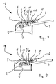
- the lever device 1 shown in the figures comprises an actuating shaft 2 for connection to a hydraulic valve (not shown) and an actuating lever 3 connected in a rotationally fixed manner to the actuating shaft 2.
- the lever device 1 further comprises a locking device 4 with an engagement part 5 which is fixed at one of its lateral edges on the actuating lever 3 and additionally at its lower end to the actuating shaft 2, and a locking part 6, which in a housing 7, which is the central Area of the lever device 1 surrounds, is held. In this case, the viewer facing wall of the housing 7 is omitted in all figures, so that the lever device 1 is visible.
- the engagement member 5 is designed as a circular segment disc whose circle center is located on the longitudinal axis of the actuating shaft 2 and the disc plane is aligned perpendicular to the longitudinal axis of the actuating shaft 2.
- the locking part 6 comprises a shaft 9 which is rotatably mounted on a bearing element 10 and a passage 11 of the locking part 6 through the housing 7, but axially non-displaceable.
- the locking part 6 is positioned such that its longitudinal axis extends substantially perpendicular to the axis of the actuating shaft 2.
- an engagement member 12 having two is substantially parallel to the longitudinal axis of the shaft 9 lying eccentric projections 13, 14 are formed, which are spaced and leave a groove between them.
- the locking part 6 has a rotary handle 15 with which the locking part 6 can be manually rotated about its longitudinal axis.
- the locking member 6 is rotated by the rotary handle 15 between a release position, in the Figures 1 and 2 is shown, and an engaged position, in the FIGS. 3 and 4 is shown to be moved.
- the two positions are separated by a rotation angle of 90 °.
- the projections 13, 14 are aligned parallel to the plane of the circular path of the pins 8.
- the circular path plane corresponds to the groove formed between the projections 13, 14, so that the pins 8 can pass freely between the projections 13, 14 when the actuating shaft 2 is actuated via the actuating lever 3.
- the actuating shaft 2 can be blocked by turning the locking member 6 by 90 ° in the engaged position.
- the projections 13, 14 are pivoted into a position in the circular path of the pin 8, so that they enclose and block the pin 8 positioned in the locking position. The thus formed positive engagement causes a blocking of the actuating shaft. 2
- each locking position corresponds to a possible hydraulic actuation.
- the locking device 4 is first transferred by turning the locking part 6 from the engaged position to the release position.
- the blockage of the actuating shaft 2 is released, so that it can be rotated via the actuating lever 3 in a different locking position, which corresponds to the desired hydraulic actuation.
- the actuating shaft 2 is blocked again by turning the locking member 6 in its engaged position.
Landscapes
- Engineering & Computer Science (AREA)
- Physics & Mathematics (AREA)
- General Physics & Mathematics (AREA)
- Automation & Control Theory (AREA)
- General Engineering & Computer Science (AREA)
- Mechanical Engineering (AREA)
- Mechanically-Actuated Valves (AREA)
- Preventing Unauthorised Actuation Of Valves (AREA)
Claims (11)
- Dispositif de levier (1) pour l'actionnement notamment d'une vanne hydraulique, avec un arbre d'actionnement (2) pour le raccordement à la vanne hydraulique et un levier d'actionnement (3) relié à l'arbre d'actionnement (2) dont la manipulation permet de faire pivoter l'arbre d'actionnement (2), et avec un dispositif de blocage (4) pour fixer l'arbre d'actionnement (2) dans plusieurs positions de blocage, sachant que le dispositif de blocage (4) présente une pièce de couplage (5) reliée à l'arbre d'actionnement (2) et/ou au levier d'actionnement (3) et une pièce de blocage (6) placée de manière à être orientée et pièce de couplage (5) et pièce de blocage (6) ont des éléments de couplage (8, 12) complémentaires les uns par rapport aux autres, sachant que l'élément de couplage (12) de la pièce de blocage (6) peut être mis dans une position de couplage à partir d'une position de déblocage à l'extérieur de la zone de mouvement de la pièce de couplage (5), dans laquelle les éléments de couplage (8, 12) de la pièce de couplage (5) et pièce de blocage (6) s'imbriquent par liaison de forme et l'arbre d'actionnement (2) par blocage, sachant que l'élément de couplage (12) sur la pièce de blocage (6) est mise de telle manière qu'il peut être basculé par mouvement de rotation de la pièce de blocage (6) de la position de déblocage dans la position de couplage, caractérisé en ce que la pièce de blocage (6) est formée en tant qu'arbre (9) logé de manière inamovible dans le sens axial, qui présente une poignée tournante (15) sur sa zone opposée à l'élément de couplage (12) et que l'élément de couplage (12) est prévu sur l'extrémité de l'arbre (9) côté pièce de couplage, sachant que l'arbre (9) est positionné de manière à ce que son axe longitudinal s'étende essentiellement verticalement par rapport à l'axe de l'arbre d'actionnement (2).
- Dispositif de levier (1) selon revendication 1, caractérisé en ce que l'élément de couplage (12) de la pièce de blocage (6) est formé en tant que deux avancées (13, 14) espacées, entre lesquelles le ou les éléments (s) de couplage (8) sur la pièce de couplage (5) peut passer dans la position de déblocage de la pièce de blocage (6).
- Dispositif de levier (1) selon l'une des revendications précédentes, caractérisé en ce que le ou les élément (s) de couplage (8) de la pièce de couplage (5) est ou sont formé (s) en tant qu'avancée ou avancées.
- Dispositif de levier (1) selon l'une des revendications précédentes, caractérisé en ce que le ou les élément (s) de couplage (8) de la pièce de couplage (5) s'avance ou s'avancent essentiellement radialement par rapport à l'arbre d'actionnement (2).
- Dispositif de levier (1) selon l'une des revendications précédentes, caractérisé en ce que la pièce de couplage (5) présente plusieurs éléments de couplage (8), sachant que chaque élément de couplage (8) de la pièce de couplage (5) peut être mis en prise avec l'élément de couplage (12) de la pièce de blocage (6).
- Dispositif de levier (1) selon revendication 5, caractérisé en ce que les éléments de couplage (8) de la pièce de couplage (5) sont placés sur une voie circulaire autour de l'arbre d'actionnement (2).
- Dispositif de levier (1) selon l'une des revendications précédentes, caractérisé en ce que la pièce de couplage (5) est exécutée en tant que disque en segment de cercle et est positionnée de telle manière que son centre de cercle se trouve sur l'axe longitudinal de l'arbre d'actionnement (2).
- Dispositif de levier (1) selon revendication 7, caractérisé en ce que le ou les élément (s) de couplage (8) de la pièce de couplage (5) est ou sont prévu (s) sur le bord extérieur du disque en segment de cercle..
- Dispositif de levier (1) selon revendication 7 ou 8, caractérisé en ce que le disque en segment de cercle (5) est positionné de telle manière que son plan de disque est aligné verticalement par rapport à l'axe longitudinal de l'arbre d'actionnement (2).
- Dispositif de levier (1) selon l'une des revendications précédentes, caractérisé en ce que la pièce de couplage (5) est placée sur le levier d'actionnement (3).
- Vanne hydraulique avec un levier d'actionnement (1) pour l'actionnement de la vanne hydraulique, caractérisée en ce que le dispositif de levier (1) est formé selon l'une des revendications précédentes.
Priority Applications (1)
| Application Number | Priority Date | Filing Date | Title |
|---|---|---|---|
| EP20090011379 EP2292957B1 (fr) | 2009-09-04 | 2009-09-04 | Dispositif de levier et soupape hydraulique dotée d'un tel dispositif de levier |
Applications Claiming Priority (1)
| Application Number | Priority Date | Filing Date | Title |
|---|---|---|---|
| EP20090011379 EP2292957B1 (fr) | 2009-09-04 | 2009-09-04 | Dispositif de levier et soupape hydraulique dotée d'un tel dispositif de levier |
Publications (2)
| Publication Number | Publication Date |
|---|---|
| EP2292957A1 EP2292957A1 (fr) | 2011-03-09 |
| EP2292957B1 true EP2292957B1 (fr) | 2012-11-14 |
Family
ID=41611192
Family Applications (1)
| Application Number | Title | Priority Date | Filing Date |
|---|---|---|---|
| EP20090011379 Active EP2292957B1 (fr) | 2009-09-04 | 2009-09-04 | Dispositif de levier et soupape hydraulique dotée d'un tel dispositif de levier |
Country Status (1)
| Country | Link |
|---|---|
| EP (1) | EP2292957B1 (fr) |
Family Cites Families (5)
| Publication number | Priority date | Publication date | Assignee | Title |
|---|---|---|---|---|
| DE604802C (de) | 1934-10-29 | Junker & Ruh A G | Sicherungseinrichtung fuer mit einer Doppelsicherung versehene Gashaehne | |
| FR527679A (fr) | 1920-08-20 | 1921-10-28 | Frederic Vogel | Dispositif de sureté pour robinets à gaz |
| GB243847A (en) | 1924-10-06 | 1925-12-10 | Harry James Yates | Improvements in taps or valves |
| GB0111759D0 (en) * | 2001-05-14 | 2001-07-04 | Ssl Int Plc | a tap |
| KR100663638B1 (ko) * | 2006-08-02 | 2007-01-05 | 양세정 | 레버형 정량 조절용 버터플라이 밸브 |
-
2009
- 2009-09-04 EP EP20090011379 patent/EP2292957B1/fr active Active
Also Published As
| Publication number | Publication date |
|---|---|
| EP2292957A1 (fr) | 2011-03-09 |
Similar Documents
| Publication | Publication Date | Title |
|---|---|---|
| DE2221013B2 (de) | Gelenkbeschlag für eine verstellbare Rückenlehne eines Sitzes | |
| DE3126760C2 (de) | Vorrichtung zum Neueinstellen des Schlüsselgeheimnisses in einem Permutationsschloß für Koffer oder dergleichen | |
| DE202015102087U1 (de) | Demontage- und Montage-Einstell-Einrichtung für Schubladenblende | |
| DE2942789A1 (de) | Permutationsschloss | |
| EP1707717A2 (fr) | Verrou rotatif à montage automatique | |
| DE102017124318B4 (de) | Befestigungsanordnung für eine Felge eines Rades | |
| DE102012012134B4 (de) | Als Kindersitz ausgebildete Sicherheitssitzvorrichtung | |
| DE19837767C2 (de) | Einrichtung zum Verbinden von hydraulischen oder pneumatischen Komponenten, insbesondere von Elektromagnetventilen miteinander | |
| DE20112976U1 (de) | Schwenkbeschlag | |
| EP3498941B1 (fr) | Élément d'actionnement pourvu d'un dispositif de verrouillage | |
| DE10217534A1 (de) | Verriegelungseinrichtung von Einstelleinrichtungen für Lenksäulen von Kraftfahrzeugen | |
| WO2025256700A1 (fr) | Fermeture | |
| EP2292957B1 (fr) | Dispositif de levier et soupape hydraulique dotée d'un tel dispositif de levier | |
| EP2142736B1 (fr) | Ferrure pour fenêtre, porte ou similaire | |
| DE102006032681B4 (de) | Gelenkbeschlag für Kraftfahrzeugsitze | |
| EP3556973A2 (fr) | Fermeture | |
| EP3557104A1 (fr) | Dispositif poignée rotatif et soupape sanitaire | |
| DE102017129057A1 (de) | Winkelverstellbares Scharnier | |
| EP2578891B1 (fr) | Adapteur | |
| EP3282058A1 (fr) | Dispositif de fixation d'un composant sanitaire, en particulier d'un cadre de fixation pour une plaque d'actionnement de wc ou d'urinoir | |
| WO2017005530A1 (fr) | Dispositif de réglage | |
| DE102014213134B4 (de) | Scheibenanordnung mit einstellbarer axialer Dicke sowie Schaltanordnung mit der Scheibenanordnung | |
| EP2181281B1 (fr) | Support de moment de rotation d'un verrou de soupape | |
| EP2438337B1 (fr) | Soutien de couple pour un verrouillage | |
| EP3636863B1 (fr) | Fixation de joint |
Legal Events
| Date | Code | Title | Description |
|---|---|---|---|
| PUAI | Public reference made under article 153(3) epc to a published international application that has entered the european phase |
Free format text: ORIGINAL CODE: 0009012 |
|
| AK | Designated contracting states |
Kind code of ref document: A1 Designated state(s): AT BE BG CH CY CZ DE DK EE ES FI FR GB GR HR HU IE IS IT LI LT LU LV MC MK MT NL NO PL PT RO SE SI SK SM TR |
|
| AX | Request for extension of the european patent |
Extension state: AL BA RS |
|
| 17P | Request for examination filed |
Effective date: 20110402 |
|
| 17Q | First examination report despatched |
Effective date: 20110504 |
|
| RIC1 | Information provided on ipc code assigned before grant |
Ipc: G05G 5/08 20060101ALI20120316BHEP Ipc: F16K 35/00 20060101AFI20120316BHEP Ipc: G05G 1/10 20060101ALI20120316BHEP Ipc: F16K 35/02 20060101ALI20120316BHEP Ipc: G05G 5/06 20060101ALI20120316BHEP |
|
| GRAP | Despatch of communication of intention to grant a patent |
Free format text: ORIGINAL CODE: EPIDOSNIGR1 |
|
| GRAS | Grant fee paid |
Free format text: ORIGINAL CODE: EPIDOSNIGR3 |
|
| GRAA | (expected) grant |
Free format text: ORIGINAL CODE: 0009210 |
|
| RAP1 | Party data changed (applicant data changed or rights of an application transferred) |
Owner name: DURA AUTOMOTIVE SYSTEMS GMBH |
|
| AK | Designated contracting states |
Kind code of ref document: B1 Designated state(s): AT BE BG CH CY CZ DE DK EE ES FI FR GB GR HR HU IE IS IT LI LT LU LV MC MK MT NL NO PL PT RO SE SI SK SM TR |
|
| REG | Reference to a national code |
Ref country code: GB Ref legal event code: FG4D Free format text: NOT ENGLISH |
|
| REG | Reference to a national code |
Ref country code: CH Ref legal event code: EP Ref country code: AT Ref legal event code: REF Ref document number: 584189 Country of ref document: AT Kind code of ref document: T Effective date: 20121115 |
|
| REG | Reference to a national code |
Ref country code: IE Ref legal event code: FG4D Free format text: LANGUAGE OF EP DOCUMENT: GERMAN |
|
| REG | Reference to a national code |
Ref country code: DE Ref legal event code: R096 Ref document number: 502009005351 Country of ref document: DE Effective date: 20130110 |
|
| REG | Reference to a national code |
Ref country code: NL Ref legal event code: VDEP Effective date: 20121114 |
|
| REG | Reference to a national code |
Ref country code: LT Ref legal event code: MG4D |
|
| PG25 | Lapsed in a contracting state [announced via postgrant information from national office to epo] |
Ref country code: FI Free format text: LAPSE BECAUSE OF FAILURE TO SUBMIT A TRANSLATION OF THE DESCRIPTION OR TO PAY THE FEE WITHIN THE PRESCRIBED TIME-LIMIT Effective date: 20121114 Ref country code: SE Free format text: LAPSE BECAUSE OF FAILURE TO SUBMIT A TRANSLATION OF THE DESCRIPTION OR TO PAY THE FEE WITHIN THE PRESCRIBED TIME-LIMIT Effective date: 20121114 Ref country code: NO Free format text: LAPSE BECAUSE OF FAILURE TO SUBMIT A TRANSLATION OF THE DESCRIPTION OR TO PAY THE FEE WITHIN THE PRESCRIBED TIME-LIMIT Effective date: 20130214 Ref country code: HR Free format text: LAPSE BECAUSE OF FAILURE TO SUBMIT A TRANSLATION OF THE DESCRIPTION OR TO PAY THE FEE WITHIN THE PRESCRIBED TIME-LIMIT Effective date: 20121114 Ref country code: ES Free format text: LAPSE BECAUSE OF FAILURE TO SUBMIT A TRANSLATION OF THE DESCRIPTION OR TO PAY THE FEE WITHIN THE PRESCRIBED TIME-LIMIT Effective date: 20130225 Ref country code: LT Free format text: LAPSE BECAUSE OF FAILURE TO SUBMIT A TRANSLATION OF THE DESCRIPTION OR TO PAY THE FEE WITHIN THE PRESCRIBED TIME-LIMIT Effective date: 20121114 |
|
| PG25 | Lapsed in a contracting state [announced via postgrant information from national office to epo] |
Ref country code: GR Free format text: LAPSE BECAUSE OF FAILURE TO SUBMIT A TRANSLATION OF THE DESCRIPTION OR TO PAY THE FEE WITHIN THE PRESCRIBED TIME-LIMIT Effective date: 20130215 Ref country code: LV Free format text: LAPSE BECAUSE OF FAILURE TO SUBMIT A TRANSLATION OF THE DESCRIPTION OR TO PAY THE FEE WITHIN THE PRESCRIBED TIME-LIMIT Effective date: 20121114 Ref country code: PT Free format text: LAPSE BECAUSE OF FAILURE TO SUBMIT A TRANSLATION OF THE DESCRIPTION OR TO PAY THE FEE WITHIN THE PRESCRIBED TIME-LIMIT Effective date: 20130314 Ref country code: PL Free format text: LAPSE BECAUSE OF FAILURE TO SUBMIT A TRANSLATION OF THE DESCRIPTION OR TO PAY THE FEE WITHIN THE PRESCRIBED TIME-LIMIT Effective date: 20121114 Ref country code: SI Free format text: LAPSE BECAUSE OF FAILURE TO SUBMIT A TRANSLATION OF THE DESCRIPTION OR TO PAY THE FEE WITHIN THE PRESCRIBED TIME-LIMIT Effective date: 20121114 |
|
| PG25 | Lapsed in a contracting state [announced via postgrant information from national office to epo] |
Ref country code: BG Free format text: LAPSE BECAUSE OF FAILURE TO SUBMIT A TRANSLATION OF THE DESCRIPTION OR TO PAY THE FEE WITHIN THE PRESCRIBED TIME-LIMIT Effective date: 20130214 Ref country code: SK Free format text: LAPSE BECAUSE OF FAILURE TO SUBMIT A TRANSLATION OF THE DESCRIPTION OR TO PAY THE FEE WITHIN THE PRESCRIBED TIME-LIMIT Effective date: 20121114 Ref country code: DK Free format text: LAPSE BECAUSE OF FAILURE TO SUBMIT A TRANSLATION OF THE DESCRIPTION OR TO PAY THE FEE WITHIN THE PRESCRIBED TIME-LIMIT Effective date: 20121114 Ref country code: EE Free format text: LAPSE BECAUSE OF FAILURE TO SUBMIT A TRANSLATION OF THE DESCRIPTION OR TO PAY THE FEE WITHIN THE PRESCRIBED TIME-LIMIT Effective date: 20121114 Ref country code: CZ Free format text: LAPSE BECAUSE OF FAILURE TO SUBMIT A TRANSLATION OF THE DESCRIPTION OR TO PAY THE FEE WITHIN THE PRESCRIBED TIME-LIMIT Effective date: 20121114 |
|
| PG25 | Lapsed in a contracting state [announced via postgrant information from national office to epo] |
Ref country code: RO Free format text: LAPSE BECAUSE OF FAILURE TO SUBMIT A TRANSLATION OF THE DESCRIPTION OR TO PAY THE FEE WITHIN THE PRESCRIBED TIME-LIMIT Effective date: 20121114 Ref country code: NL Free format text: LAPSE BECAUSE OF FAILURE TO SUBMIT A TRANSLATION OF THE DESCRIPTION OR TO PAY THE FEE WITHIN THE PRESCRIBED TIME-LIMIT Effective date: 20121114 |
|
| PLBE | No opposition filed within time limit |
Free format text: ORIGINAL CODE: 0009261 |
|
| STAA | Information on the status of an ep patent application or granted ep patent |
Free format text: STATUS: NO OPPOSITION FILED WITHIN TIME LIMIT |
|
| 26N | No opposition filed |
Effective date: 20130815 |
|
| PG25 | Lapsed in a contracting state [announced via postgrant information from national office to epo] |
Ref country code: CY Free format text: LAPSE BECAUSE OF FAILURE TO SUBMIT A TRANSLATION OF THE DESCRIPTION OR TO PAY THE FEE WITHIN THE PRESCRIBED TIME-LIMIT Effective date: 20121114 |
|
| REG | Reference to a national code |
Ref country code: DE Ref legal event code: R097 Ref document number: 502009005351 Country of ref document: DE Effective date: 20130815 |
|
| BERE | Be: lapsed |
Owner name: DURA AUTOMOTIVE SYSTEMS G.M.B.H. Effective date: 20130930 |
|
| PG25 | Lapsed in a contracting state [announced via postgrant information from national office to epo] |
Ref country code: MC Free format text: LAPSE BECAUSE OF FAILURE TO SUBMIT A TRANSLATION OF THE DESCRIPTION OR TO PAY THE FEE WITHIN THE PRESCRIBED TIME-LIMIT Effective date: 20121114 |
|
| REG | Reference to a national code |
Ref country code: CH Ref legal event code: PL |
|
| REG | Reference to a national code |
Ref country code: IE Ref legal event code: MM4A |
|
| PG25 | Lapsed in a contracting state [announced via postgrant information from national office to epo] |
Ref country code: BE Free format text: LAPSE BECAUSE OF NON-PAYMENT OF DUE FEES Effective date: 20130930 Ref country code: LI Free format text: LAPSE BECAUSE OF NON-PAYMENT OF DUE FEES Effective date: 20130930 Ref country code: CH Free format text: LAPSE BECAUSE OF NON-PAYMENT OF DUE FEES Effective date: 20130930 Ref country code: IE Free format text: LAPSE BECAUSE OF NON-PAYMENT OF DUE FEES Effective date: 20130904 |
|
| PG25 | Lapsed in a contracting state [announced via postgrant information from national office to epo] |
Ref country code: SM Free format text: LAPSE BECAUSE OF FAILURE TO SUBMIT A TRANSLATION OF THE DESCRIPTION OR TO PAY THE FEE WITHIN THE PRESCRIBED TIME-LIMIT Effective date: 20121114 |
|
| PG25 | Lapsed in a contracting state [announced via postgrant information from national office to epo] |
Ref country code: MT Free format text: LAPSE BECAUSE OF FAILURE TO SUBMIT A TRANSLATION OF THE DESCRIPTION OR TO PAY THE FEE WITHIN THE PRESCRIBED TIME-LIMIT Effective date: 20121114 |
|
| PG25 | Lapsed in a contracting state [announced via postgrant information from national office to epo] |
Ref country code: LU Free format text: LAPSE BECAUSE OF NON-PAYMENT OF DUE FEES Effective date: 20130904 Ref country code: MK Free format text: LAPSE BECAUSE OF FAILURE TO SUBMIT A TRANSLATION OF THE DESCRIPTION OR TO PAY THE FEE WITHIN THE PRESCRIBED TIME-LIMIT Effective date: 20121114 Ref country code: HU Free format text: LAPSE BECAUSE OF FAILURE TO SUBMIT A TRANSLATION OF THE DESCRIPTION OR TO PAY THE FEE WITHIN THE PRESCRIBED TIME-LIMIT; INVALID AB INITIO Effective date: 20090904 |
|
| PG25 | Lapsed in a contracting state [announced via postgrant information from national office to epo] |
Ref country code: IS Free format text: LAPSE BECAUSE OF FAILURE TO SUBMIT A TRANSLATION OF THE DESCRIPTION OR TO PAY THE FEE WITHIN THE PRESCRIBED TIME-LIMIT Effective date: 20121114 |
|
| REG | Reference to a national code |
Ref country code: FR Ref legal event code: PLFP Year of fee payment: 8 |
|
| REG | Reference to a national code |
Ref country code: FR Ref legal event code: PLFP Year of fee payment: 9 |
|
| PGFP | Annual fee paid to national office [announced via postgrant information from national office to epo] |
Ref country code: ES Payment date: 20180702 Year of fee payment: 14 |
|
| PGFP | Annual fee paid to national office [announced via postgrant information from national office to epo] |
Ref country code: AT Payment date: 20170920 Year of fee payment: 9 Ref country code: TR Payment date: 20170920 Year of fee payment: 9 |
|
| REG | Reference to a national code |
Ref country code: FR Ref legal event code: PLFP Year of fee payment: 10 |
|
| REG | Reference to a national code |
Ref country code: AT Ref legal event code: MM01 Ref document number: 584189 Country of ref document: AT Kind code of ref document: T Effective date: 20180904 |
|
| PG25 | Lapsed in a contracting state [announced via postgrant information from national office to epo] |
Ref country code: IT Free format text: LAPSE BECAUSE OF NON-PAYMENT OF DUE FEES Effective date: 20180904 |
|
| PG25 | Lapsed in a contracting state [announced via postgrant information from national office to epo] |
Ref country code: AT Free format text: LAPSE BECAUSE OF NON-PAYMENT OF DUE FEES Effective date: 20180904 |
|
| PG25 | Lapsed in a contracting state [announced via postgrant information from national office to epo] |
Ref country code: TR Free format text: LAPSE BECAUSE OF NON-PAYMENT OF DUE FEES Effective date: 20180904 |
|
| PGFP | Annual fee paid to national office [announced via postgrant information from national office to epo] |
Ref country code: DE Payment date: 20250929 Year of fee payment: 17 |
|
| PGFP | Annual fee paid to national office [announced via postgrant information from national office to epo] |
Ref country code: GB Payment date: 20250929 Year of fee payment: 17 |
|
| PGFP | Annual fee paid to national office [announced via postgrant information from national office to epo] |
Ref country code: FR Payment date: 20250925 Year of fee payment: 17 |